instruction manual - rocktron 1. introduction congratulations on your purchase of the rocktron...
TRANSCRIPT

1
Instruction Manual
reg
HUSH reg is a registered trademark of GHS Corporation
2
Copyright copy 2013-12 GHS CorporationAll Rights Reserved
Your HUSHreg Ultra noise reduction system has been tested and complies with the following Stan-dards and Directives as set forth by the European Union
Council Directive(s) 89336EEC Electromagnetic Compatibility
Standard(s) EN55013 EN50082-1
This means that this product has been designed to meet stringent guidelines on how much RF energy it can emit and that it should be immune from other sources of interference when properly used Improper use of this equipment could result in increased RF emissions which may or may not interfere with other electronic products
To insure against this possibility always use good shielded cables for all audio input and output connections Also bundle audio cables separately from the AC power cables These steps will help insure compliance with the Directive(s)
For more information about other Rocktron products please see your local dealer or one of our importers closest to you (listed on the enclosed warranty sheet)
3
CONTENTS1 Introduction 4
2 HUSH Ultra Front Panel 6
3 HUSH Ultra Back Panel 7
4 Quick Start 8
5 HUSH amp GATE Threshold Controls 9
6 System Connections 10
7 HUSH Description 14
8 HUSH Ultra Edit Mode (Functions amp Parameters) 16 1048697 TITLE E DIT Function 17 1048697 TRUE BYPASS INOUT Function 17 1048697 HUSHreg Function 18 1048697 GLOBAL Function 19 1048697 MIDI CTRLINK Function 21 1048697 PRE SE T MAPPING Function 22 1048697 MIDI DUMPLOAD Function 22 1048697 FUNCTION amp PARAME TE R RANGE Listings 23
9OperatingtheHUSHUltra 24 1048697 Display Description 24 1048697 Selecting a preset 25 1048697 Changing preset parameters 26 1048697 Storing changed preset parameters 27 1048697 Title E d it 28 1048697 Preset Mapping 30 1048697 MIDI DUMPLOAD 31 1048697 MIDI IN 33 1048697 MIDI THRUOUT 33 1048697 Phantom Power 34
10HUSHUltraSpecifications 35
4
1 IntroductionCongratulations on your purchase of the Rocktron HUSHreg Ultra
The HUSH Ultra is the ultimate noise reducing eliminating and exterminating processor The HUSH Ultrarsquos innovative digital stereo noise exterminator provides two channels of the same world renowned professional noise reduction patented by Rocktron and used for years in thousands and thousands of guitar rigs and recording stud iosTheHUSHUltrafeaturesTrueBy pass anLCDd isplay and programmablepresets with MIDI control allowing you to tailor your HUSH settings on individual presetstosuity ourneed sTheHUSHUltraprovid esBOTH14rdquoand XLRinputsand outputs and is easy to setup and easy to use
Wipe out noise eliminate hiss crackle and other noise problems with the very best noise reduction circuitry available today
5
OPERATING PRECAUTIONS
NOTE IT ISVE RY IMPORTANT THATYOU RE ADTHIS SE CTIONTOPROVIDE YE ARSOFTROUBLE FRE E USE THISUNITRE QUIRE SCARE -FULHANDLING
All warnings on this equipment and in the operating instructions should be adhered to and all operating instructions should be followedDo not use this equipment near water Care should be taken so that objects do not fall and liquids are not spilled into the unit through any openingsThe power cord should be unplugged from the outlet when left unused for a long period of time
DONOTATTE MPTTO SE RVICE THIS E QUIPME NT THIS E QUIPME NTSHOULD BE SE RVICE D BY QUALIFIE D PE RSONNE L ONLY DO NOTMAK E ANYINTE RNALADJUSTME NTSORADDITIONSTOTHISE QUIP-ME NTATANYTIME DONOTTAMPE RWITHINTE RNALE LE CTRONICCOMPONE NTSATANYTIME FAILURE TOFOLLOWTHE SE INSTRUC-TIONSMAYVOIDTHE WARRANTYOFTHISE QUIPME NT ASWE LLASCAUSINGSHOCK HAZARD
POWER REQUIREMENTS
This unit accepts power from the 9VAC15A ad aptor supplied with the unitThis 9 volt RMS AC voltage is internally processed by a voltage doubler which generates a bipolar plusmn15 volts to maintain the headroom and sound quality of professional studio quality equipment Using an external power source such as this minimizes excessive noise and hum problems often associated with internal transformers providing optimal performance for the user
OPERATING TEMPERATURE
Do not expose this unit to excessive heat This unit is designed to operate be-tween 32deg F and 104deg F (0deg C and 40deg C) This unit may not function properly under extreme temperatures
6
PRESET SELECTFUNCTION SELECTUse this knob to select the different presets available within the HUSH Ultra See section titled SELECTING A PRESET for more information on how to select a preset When in EDIT MODE it is used to select the desired FUNCTION (Title Edit True Bypass HUSH Global MIDI CTRLINK Preset Mapping MIDI DumpLoad or Global Restore) to be altered See section titled CHANGING PRESET PARAMETERS in this manual for more information on the FUNCTION SELECT control
TRUE BYPASS INOUT button amp LEDThis switch marked as INOUT allows for the HUSH Ultra to be bypassed when noise reduction is not required When lit the green LED indicates that the HUSH Ultra is in TRUE BYPASS mode Thus the HUSH Ultra is not active and your signal is passing through the HUSH Ultra unaffected DISPLAY windowAll of the HUSH Ultras presets functions and parameters will be displayed in this window depending on what is being selected or adjusted
STOREEDIT buttonThis button is used to STORE any changes you make to presets It is also used to put the HUSH Ultra into PRESET EDIT Mode See PRESET EDIT mode later in this manual for more details on this function
HUSH THRESHOLDPARAMETER ADJUST This control sets the point at which the downward expander and dynamic filter begin to operate When in EDIT MODE this control is used to ADJUST the selected PARAMETER within the selected FUNCTION See section titled CHANGING PRESET PARAMETERS in this manual for more information on the PARAMETER ADJUST control
GATE THRESHOLDPARAMETER SELECT This control is used to determine the level at which the gate will begin to operate As the input signal drops below this level the gate will activate and downward expansion will begin When in EDIT MODE this control is used to SELECT a parameter with the selected FUNCTION to be altered See section titled CHANGING PRESET PARAMETERS in this manual for more information on the PARAMETER SELECT control
GATE RELEASE LEDWhen lit the Gate Release LED indicates that the input signal has dropped below the level set by the Gate Threshold control thus activating the gate and providing additional downward expansion
REF switchThis switch determines the sensitivity of the HUSH Ultra When using the HUSH Ultra with professional audio equip-ment providing a nominal output level +4dB it is recommended that the +4dB setting on the unit as the Threshold adjustment will allow you to optimize noise reduction for this reference level
If the -10 setting is used and the unit is overdriven the +4 setting should be used
The -10db setting is recommended for all instrument rigs
2HUSHULTRAFrontPanel
1
2
3
4
5
6
7
8
7
CH A (MONO) IN jacksThis XLR and frac14 mono jack provide inputs to the left channel of the HUSH Ultra Use either the XLR jack or the frac14 jack when connecting but not both together When using only one input use the CH A (MONO) XLR or frac14 jack
CH B IN jacksThis XLR and frac14 mono jack provide inputs to the right channel of the HUSH Ultra Use either the XLR jack or the frac14 jack when connecting but not both together
CH A jacksThis XLR and frac14 mono jack provide the output from the CH A (MONO) channel of the HUSH Ultra
CH B jacksThis XLR and frac14 mono jack provide the output from the CH B channel of the HUSH Ultra
Note When CH A is used as a single signal source the signal will be present in both the CH A and CH B outputs
PHANTOM POWER jackThis 25mm pin jack accepts power from the 9VAC adapter supplied with a Rocktron foot controller (sold seperately) See section called PHANTOM POWER for more information
MIDI IN jackUse this jack to plug in your MIDI controller This jack is a 7 Pin MIDI Jack however a standard 5 Pin MIDI Cable can be used If plugging into a Rocktron MIDI controller such as the All Access MIDI Mate or MIDI Xchange we recommend using the Rocktron RMM900 7-Pin MIDI Cable (sold separately) Pins 6 and 7 supply phantom power to the Rocktron MIDI controller when using the RMM900
MIDI THRUOUT jackUse this jack to plug into the first MIDI controllable device in your signal chain
POWER jackPlug the included 9VAC adapter into this jack to provide power to the unit Please follow all precautions as outlined in this manual and the manuals of the products that are being plugged into the HUSH Ultra Failure to follow these precautions may void the warranty
3HUSHULTRARearPanel
1
2
3
4
5
6
7
8
8
The HUSH ULTRA default operation settings are
MIDICHANNE L=OMNI
PROGRAMCHANGE S=ON
PROGRAMMAPPING=OFF
HUSHACTIVE =IN
PROGRAMMING PRESETS
1Choosepresetnumberby turningthePRE SE TFUNCTIONSE LE CTK noboruseMid iController
2Ad justHushthreshold controltoeliminatenoiseand hissby turningtheHUSHTHRE SHOLDPARAME TE RSE LE CTK nob
3Ad justGateThreshold by usingtheGATE THRE SHOLDPARAME TE RSE LE CTknob
Note If you want desired preset to be a True Bypass preset press the Bypass button now
4Pressand releasetheSTORE E DITbuttontosavey ourchanges
5Thed isplay willblinkldquoSTORE ATPRE SE Tldquo
Notetocancelthestoremod eatany timeturnthePARAME TE RADJUSTK NOB
6UsethePRE SE TFUNCTIONSE LE CTknoband pickthed estinationpresetwherey ouwould liketosavey ourchanges
7Pressand releasetheSTORE E DITbutton
You must adjust the Hush Threshold or Gate Threshold in order to use the store function When not in the EDIT mode if you want to store the current changes to the preset the store button must be pressed within 5 seconds after theinitialchangeAfter5secstheHUSHULTRAwillreturntothepresetnamestand by mod eTostorethechangessimply re-adjust either the Hush Threshold or Gate Threshold and press store
HUSH Ultra Quick Start
9
HUSH THRESHOLD CONTROLThe front panel HUSH Threshold control determines the minimum input level at which the HUSH filter and downward expander will begin to operate Setting this control too high will result in a loss of sustain as notes will tend to die out much faster than they should Conversely when set too low the expander will close too late (if at all) and the noise floor will remain audible
GATE THRESHOLD CONTROLThe other half of the HUSH Ultra consists of a noise gate A noise gate completely shuts off the output signal when the input signalleveld ropsbelowaprescribed threshold level(volume)OntheHUSHUltra thisthreshold isd etermined by theGateThreshold control on the front panel This control should be set so that it doesnt cut notes off (ie set too high) yet doesnt activatelongafteranoteend s(allowingthenoisefloortoremainaud ible)
Thiscircuitiscombined withtheVariableIntegrated Release(VIR)circuittoprovid eaninternalvariablereleasetothed ownward expand erWiththeVIRcircuit iftheguitarsignald ecay sslowly thed ownward expand erwillengageslowly Iftheguitarsignalstopsquickly thed ownward expand erwillengagequickly TheLE Dind icateswhend ownward expan-sion is active
HUSHamp GATE THRE SHOLD
10
This connection is an example of a mono connection from a preamp and a multi-effects processor
System Connections
11
This connection is an example of a stereo connection from a stereo preamp and multi-effects processor
System Connections
12
This is a connection example of how you can connect the HUSH Ultra to use with a guitar amp head
System Connections
13
This is a connection example of how you can connect the HUSH Ultra to use with a guitar amp combo
System Connections
14
When used properly the HUSH Ultra should be completely transparent (ie it should not effect the audio signalmdashonly the noise) To maximize the performance of the HUSH Ultra it is necessary to understand its front panel controls and how they work together By understanding how these controls work it will be easier to cor-rectly set up the HUSH Ultra to suit any application
The HUSH Ultra front panel provides two controls which each manipulate both channels simultaneously The HUSH Threshold control sets the amount of noise reduction required for a given input signal while the Gate Threshold control provides additional downward expansion when increased (The Gate Threshold con-trol may also be used by itself allowing the unit to be used as strictly a downward expander)
HUSHreg Section
Rocktrons patented HUSH noise reduction is a single-ended system that com-bines the principles of dynamic filtering and low-level downward expansion
Dynamic Filtering
Dynamic filtering is achieved by dynamically-controlling a low pass filter to open and close the bandwidth of the output signal depending upon the amount of mid and high band information present in the input signal The filter bandwidth will only open far enough to pass the highest frequency information in the input signal thus reducing the noise above it
For example if the highest frequency present in the input signal is 8kHz the filter will open to pass up to 8kHz while the noise from 8kHz to 20kHz would be reduced If a signal with frequency components up to 20kHz appears at the input the dynamic filter will open to its full extreme (40kHz)
HUSH Description
15
As the input signal drops further below the threshold point downward expansion increases A drop in the input level by 20dB would cause the output level to drop approximately 40dB (ie 20dB of gain reduction) In the absence of any input signal the expander will reduce the gain so that the noise floor becomes inaudible
This means that if a signal is present at the input which consists of primar-ily bass components the dynamic filter will reduce mid or high band noise If no mid or high band information is present the filter will close down to a pre-set cut-off point of 1kHz (allowing only frequencies of 1kHz and below to pass) However if the input signal has high frequency components present the dynamic filter will open fully to pass the signal and eliminate the possibility of a loss of high end frequency response
Downward Expansion
The second half of the HUSH process incorporates downward expansion The low level expander of the HUSH system operates like an electronic volume controlTheHUSHsy stemutilizesavoltage-controlled amplifier (VCA)circuitwhich can control the gain between the input and the output from unity to 30 40 or even 50dB of gain reduction When the input signal is above the user pre-set threshold point theVCAcircuit remainsatunity gain (Thismeans that theoutput signal level is equal to the input signal level) As the input signal level drops below the user preset threshold point downward expansion begins It is at this point that the expander acts like an electronic volume control and gradually begins to decrease the output signal level relative to the input signal level
16
E achHUSHUltrapreset isd ivid ed up into ind ivid ualblockscalled FUNCTIONS (suchasGlobal TrueBy pass HUSH ChannelLink TitleE d it MIDIDumpLoad and GlobalRestore)Within each function of each configuration is a set of controls which allow you to manipulate vari-ous aspects of that function These controls are called PARAMETERS It is the setting of each of the parameters which determines the overall soundaction of each preset
Toaccess theseFUNCTIONSand PARAME TE RS y oumust first enter into the E DITMODE
TheHUSHUltra is setup toallowy ou to first accesseach function (via theFUNCTIONSE LE CTknob) then theparameter list foreach function (via thePARAME TE RSE LE CTknob)and finally thead justablevalue foreachparameter (via thePARAME TE RADJUSTknob)
The functions available for each preset are dependent upon which effect is currently recalled The remainder of this section will describe each of the effect-based functions and the associated adjustable parameters they provide
The remaining functions are utility-based and are described in the section titled Operating the HUSH Ultra
Functions and Parameters Descriptions
Edit Mode
17
TITLE EDIT Function
The Title Edit function allows you to create a unique name for your preset The Parameter select knob is used to move the cursor The Parameter adjust knob is used to change the character in the title
TITLE EDIT
PARAME TE RSE LE CT=CHARACTE RPOSITION
PARAME TE RADJUST=CHARACTE RSE LE CT
IMPORTANTWheny ouhavecompleted ed itingtheTITLE y oumustexecuteSTORE beforeleavingtheTITLE EDIT function
Thenext functiond isplay ed after turning theFUNCTIONSE LE CTknob is the True-By passfunction
The PARAMETER SELECT knob will allow you to access these Global parameters
TRUE BYPASS Function
ThisTBYPASSparameterallowsy ou to select either ONor OFF WhenON theTrueBy pass is activeand the signalpassesd irectly through theHUSHUltraunaffected WhenOFF is selected theunit is activeand TrueBy pass isoff and HUSH is active
TBYPASS
TRUE BYPASSuseshighquality relay stoperformatotalby passoftheHUSHULTRAwhenus-ing the frac14 jacks
Thismay beactivated intheE DITMODE orviatheTRUE BYPASSbuttononthefrontpanelind icated asINOUTonthefrontoftheHUSHUltraWhenTRUE BYPASSisontheGreenLE Dwillbelit
True bypass state will be stored into the preset
TRUE BYPASS
TBYPASS OFFON TBYPASSMCC OFF120 MCCassigned toTBYPASS
Note TBYPASS MCC is programmable per preset
18
HUSHreg Function
TheHUSHIOparameter simply d etermineswhether theHUSHreg circuit is activefor thecurrentpreset WhenIN is selected theHUSH isactive WhenOUTis selected theHUSH is OFF
TheE XPTHRE SHOLD(E xpand erThreshold )parameterd etermines the levelatwhichd ownward expansionbeginsForexample if theE XPTHRE SHOLDwasset at -20(dB) and the input signal dropped below -20(dB) downward expansion would begin
TheGATE THRE SHOLDhiscontrol isused tod etermine the levelatwhich thegate will begin to operate As the input signal drops below this level the gate will activate and downward expansion will begin
HUSH IO
EXPTHRESH1
GATETHRESH1
HUSH INOUTHUSH_ THRSH_A 1 64GATE_ THRSH_A 1 64 HUSH_ THRSH_B 1 64 GATE_ THRSH_B 1 64 HUSH_ THRSH_C 1 64 GATE_ THRSH_C 1 64 HUSH_ THRSH_D 1 64 GATE_ THRSH_D 1 64
Only used whenMIDIMCCLINK isactive
19
Theparametersprovid ed in this functionaffectALLpresets (ie the settings stored for theseparametersare the same for all presets)
The PARAMETER SELECT knob will allow you to access these Global parameters
GLOBAL Function
TheHUSHOFFSE Tparameterallowsy ou toglobally (allpresets) ad just theHUSHreg Ex-pander Threshold This means that if this parameter is altered from 0(dB) to +3(dB) the Expander Threshold will be 3dB higher for all presets This feature can be useful when switching from a quiet guitar with passive electronics to a noisy guitar with active elec-tronics as the active guitar would require a higher Threshold level in all presets
MIDIRE CE IVE CHANNE L-116OMIThed efault setting isOMNI
ThePROGRAMCHANGE Sfunctionallowsy ou toglobally turnONOFF theHUSHUl-tra toacceptProgramChanges fromotherd evices Thed efault setting isON
ThePRE SE TMAPfunctionallowsy ou toglobally turnONOFF thePRE SE TMAPPINGfunction The preset mapping allows the HUSH Ultra to receive a Program Change from a MIDI Controller for one preset but to actually recall a different preset See PRESET MAPPING section later in this manual for more detailed information on PRESET MAP-PING
TheCHNLINK ldquoONOFFrdquod etermineswhethertheCHNLINK FunctionisactiveorldquoONrdquoornotactiveorldquoOFFrdquo
CONTINUOUSCONTROLLE RNUMBE R
E XPANDE RTHRE SHOLD1parameterd eterminesthelevelatwhichd ownward expansionbeginsForexample iftheE XPTHRE SHOLDwassetat-20(d B)and the input signal dropped below -20(dB) downward expansion would begin
GATE THRE SHOLD1controlisused tod eterminethelevelatwhichthegatewillbegin to operate As the input signal drops below this level the gate will activate and downward expansion will begin
E XPANDE RTHRE SHOLD2parameterd eterminesthelevelatwhichd ownward expansionbeginsForexample iftheE XPTHRE SHOLD2wassetat-20(d B)and the input signal dropped below -20(dB) downward expansion would begin Note thatthisisonly used withtheMIDIMCCLinkisactive
GATE THRE SHOLD2controlisused tod eterminethelevelatwhichthegatewillbegin to operate As the input signal drops below this level the gate will activate and downward expansion will begin Note that this is only used with the MIDI MCCLinkisactive
E XPANDE RTHRE SHOLD3parameterd eterminesthelevelatwhichd ownward expansionbeginsForexample iftheE XPTHRE SHOLD3wassetat-20(d B)and the input signal dropped below -20(dB) downward expansion would begin Note thatthisisonly used withtheMIDIMCCLinkisactive
HUSH OFFSET
MIDI RX
PROGRAM CHANGES
PRESET MAP
CHNLINK
CC_NUM
EXP THRESH1
GATE THRESH1
EXP THRESH2
GATE THRESH2
EXP THRESH3
20
GATE THRE SHOLD3controlisused tod eterminethelevelatwhichthegatewillbegin to operate As the input signal drops below this level the gate will activate and downward expansion will begin Note that this is only used with the MIDI MCCLinkisactive
E XPANDE RTHRE SHOLD4parameterd eterminesthelevelatwhichd ownward expansionbeginsForexample iftheE XPTHRE SHOLD4wassetat-20(d B)and the input signal dropped below -20(dB) downward expansion would begin Note thatthisisonly used withtheMIDIMCCLinkisactive
GATE THRE SHOLD4controlisused tod eterminethelevelatwhichthegatewillbegin to operate As the input signal drops below this level the gate will activate and downward expansion will begin Note that this is only used with the MIDI MCCLinkisactive
GATE THRESH3
EXP THRESH4
GATE THRESH4
GLOBAL Function continued
21
MIDI CTRLINK
For most users using individual presets will cover your needs however there are some power users that may desire to consider the following Ify ouhavea4channelamplifierthaty oucanuse4controllerstochangechannelsy oucanprogram1presetusingtheMCCLINK
CTRLINK OFFDetermineswhetherfunctionisactive
CC_NUM_AOFF120Assignscontrollernumber
This correlates to recall HUSH_ THRSH_A and HUSH_ GATE_A when determined that the control-ler assigned matches and that a value greater than 63 has been detected as the channel select valueThis will function with latching and momentary switching
DE FAULTMCCCC_NUM_A will map to HUSH_ THRSH_A and HUSH_ GATE_A parameters 85CC_NUM_B will map to HUSH_ THRSH_B and HUSH_ GATE_B parameters 86CC_NUM_C will map to HUSH_ THRSH_C and HUSH_ GATE_C parameters 87CC_NUM_D will map to HUSH_ THRSH_D and HUSH_ GATE_D parameters 88TBYPASS MCC controller to be used for TRUE BYPASS 89
NoteItisrecommend ed thatPROGRAMCHANGE SintheGLOBALFUNCTIONissettooffwhenusingtheMCCLINK mod eMCCLINK isprogrammableperpresetifacombinationofpro-gramchangesand theMCCLINK isd esired WhentheCTRLINK isonand y ouareoutoftheE DITMODE and y ouhavesentany ofthemapped controllerstotheHushUltratheHushThreshold and Gate Threshold controls will automatically map to the appropriate selection HUSH_ THRSH_A B C or D Example A Midi controller sends MCC 87 with a value of 127 when you adjust the Hush Threshold y ouwillseeHUSH_THRSH_Conthed isplay ThustheHUSHULTRAknowsthatsetCis currently being used
22
PRESET MAPPING Function
The Preset Mapping function allows you to use a MIDI Controller to recall different presets via program changes
MIDIRE CE IVE DPROGRAMCHANGE number ison the left sid eof the screen
The PRESET that will be recalled is on the right side of the screen
NotePRE SE TMAP in theGLOBALFUNCTIONmustbe set toONformappingto be active
PRESET MAPPING
MIDI DUMPLOAD Function
This function allows you to dump 1 preset from one HUSH Ultra to a second HUSH Ultra or a MIDI sequencer device
This functionallowsy ou tod umpALLpresets fromoneHUSHUltra toasecond HUSH Ultra or MIDI sequencer device
1 PR DUMPLOAD
BULK DUMPLOAD
23
FUNCTION PARAMETER LIST RANGE(viaFUNCTIONSE LE CT) (viaPARAME TE RSE LE CT) (viaPARAME TE RADJUST)
TITLE E DIT XXXXXXXXX
TRUE BYPASS TBYPASS OFF ON
HUSH HUSH(HushInOut) Out In E XPTHRE SH1(E xpand erThreshold Level) 164 GATE THRSH1(GateThreshold Level) 164
GLOBAL HUSHOFFSE T -10(d B)to+30(d B) MIDIRE CV 116 OMNI PROGRAMCHANGE S OFFON PRE SE TMAP OFFON CTRLINK OFFON CC_NUM_A 0TO120 CC_NUM_B 0TO120 CC_NUM_C 0TO120 CC_NUM_D 0TO120 TBYPASSMCC 0TO120 E XPTHRSH1(E xpand erThreshold Level) 164 GATE THRSH1(GateThreshold Level) 164 E XPTHRSH2(E xpand erThreshold Level) 164 GATE THRSH2(GateThreshold Level) 164 E XPTHRSH3(E xpand erThreshold Level) 164 GATE THRSH3(GateThreshold Level) 164 E XPTHRSH4(E xpand erThreshold Level) 164 GATE THRSH4(GateThreshold Level) 164
PRESET MAPPING 1MAPTO1 2MAPTO2 etc
MIDIDUMPLOAD 1PRDUMPLOAD BULK DUMPLOAD
VE RSIONNUMBE R XXXXXXXXX
Function Parameter Range Listing
24
Operating the HUSH Ultra
Top line of display will showPRESET NUMBER - Displays the Preset Number you have selected PRE SE TTITLE -ThisistheNAME ofthepreset-intheexamplebelow-USE R1
Display Description
TheLCDd isplay ontheHUSHUltraprovid esy ouwiththeinformationaboutthepresety ouarein
1 u s e r 1
PRESET NAMEPRESET NUMBER
The HUSH Ultra provides 128 stored presets Any of the 128 presets can be called up at any time via the PRESET knob or via a MIDI Controller
Each preset has the following Functions available at all times
TITLE E DITTRUE BYPASS HUSHreg GLOBALMIDICTRLINK PRESET MAPPING MIDIDUMPLOADVE RSIONNUMBE R
25
SELECTING A PRESET
1
There are two ways to select a preset on the HUSH Ultra You can either turn the PRESET knob to the desired preset you wish to recall The display will show the selected preset number
Thesecond way toselectapresetwithaMIDIControllersuchastheRocktronMIDIXchange MIDIMate AllAccessorAllAccessLTDSeesectiononMIDIConnectiononhowtoconnectaMIDIPed alto the HUSH Ultra and follow all instructions that come with your MIDI Pedal
1 u s e r 1
1 Turn the preset select knob to the desired preset
2 u s e r 2
26
NOTE Ify ouhavechanged aparametertheSTORE LE DwilllightThechange(s)thaty oumad ewillnotbestored untily ouhavepressed theSTORE buttonPleasefollowinstructionsonthenextpage for details on how to store changed parameters
CHANGING PRESET PARAMETERS
M I D I R X O M N I
G L O B A L
STE P1-E nterE DITMODE by pressingtheSTORE E DITbuttonasshownaboveWheninE DITMODE thed isplay willshowy ouareinE DITMODE onthetopline
STE P2-ToaccessthefirstFUNCTIONtobead justed turnthePRE SE TFUNCTIONSE LE CTknob The display will then show
G L O B A L
E D I T M O D E
STE P3-ToaccessthefirstPARAME TE Rtobead justed turntheGATE THRE SHOLDPARAM-E TE RSE LE CTknobThed isplay willthenshow
M I D I R X 1 6
G L O B A L
STE P4-Toad justtheselected PARAME TE R turntheHUSHTHRE SHOLDPARAME TE RAD-JUSTknobThed isplay willthenshowthead justed parameter
27
STORING CHANGED PRESET PARAMETERS
Whileviewingafunctionorparametertitle presstheSTORE buttontostartthestoreproced ureTheword sSTORE ATPRE SE Twillnowbeflashingund erthechanged presetnameasshownbelowIfy ouwould liketostorethechangesmad eatthecurrentpreset simply presstheSTORE E DITbut-tonagainand thechangeswillbestored Theword STORE Dwillflashonceand thepresetwillbestored
If you like to store the changes made at a different preset number while viewing a function or parameter title presstheSTORE buttontostartthestoreproced ureTheword sSTORE ATPRE SE Twillnowbeflashingund erthechanged presetnameNextturnthePRE SE TSE LE CTknobtothed esired presetnumberand presstheSTORE E DITbuttonTheword STORE Dwillflashonceand thepresetwillbestored at the selected preset
1 u s e R 1
S T O R E A T P R E S E T
2 U S E R 1
S T O R E A T P R E S E T
1 u s e R 1
S T O R E A T P R E S E T
1 u s e R 1
S T O R E d
1 u s e R 1
2 u s e R 1
STORE CHANGES AT THE SAME PRESET
STORE CHANGES AT A NEW PRESET
28
TobegintheTitleE d itfunction turntheFUNCTIONSE LE CTknobclockwiseuntiltheHUSHUltrad isplay sTITLE E DIT
Step 1
TurnthePARAME TE RSE LE CTknobclockwisetoinitiatetheTitleE d itmod eTurning this knob will also select the character above the part of the current title to be ed ited Thelettertobead justed willhaveaflashingboxoverthecharacterselected
Step 2
UsethePARAME TE RADJUSTknobtoselectthed esired characterforthecurrentposition(flashingbox)
Step 3
t i t l e e d i t
t i t l e e d i t
1 U s e r 1 8
(Flashing box)
Title Edit
Character to be changed
t i t l e e d i t
1 h U s e r 1 8
(Flashing box)
Character to be changed
29
Toed itthenextcharacterinthenextposition turnthePARAME TE RSE LE CTknobonestepclockwiseTheflashingboxwillmovetothenextcharactertobead justed
Step 4
NOTE The STORE button must be pressed to save the new title Exiting the Title Edit func-tion before pressing the STORE button will erase any editing that was done in Title Edit Also after flashing STORED the HUSH Ultra will exit the title edit mode and return to the main preset number
After all the characters have been edited as needed press the STORE button to save the new title to memory The HUSH Ultra will flash STORED briefly
Step 5
Title Edit continued
t i t l e e d i t
1 h u U s e r 1 8
(Flashing box)
Character to be changed
1 h u s h u l t r a
30
NowthePARAME TE RSE LE CTcorrelatestotheMIDIRE CE IVE DPRO-GRAM CHANGE number (number on the left side of screen)
ThePARAME TE RADJUSTselectsthePRE SE Tthatwillberecalled (Numberon the right side of the screen) when the received program change is executed
InaboveexampletheHUSHULTRAreceived aPROGRAMCHANGE fromamidi controller for preset 1 The actual preset recalled will be 15
NotePRE SE TMAPintheGLOBALFUNCTIONmustbesettoONformap-ping to be active
IMPORTANT
Aftery ouhavecompleted ally ourpresetmappingy oumustexecuteSTORE before leaving the PRESET MAPPING function
PRESET MAPPING Function
Step 2
Step 3
Step 1 UseFUNCTIONSE LE CTwhileinE DITMODE toselectthePRE SE TMAP-PING function
TurnthePARAME TE RSE LE CTtoentertheMAPPINGMODE
P R E S E T M A P P I N G
P R E S E T M A P P I N G
1 M A P T O 1 5
31
Any or all of the HUSH Ultras presets may be dumped to another HUSH Ultra a sequencer or MIDI utility programusingaPCmid iinterfacetocreatea(sy x)fileAlltheinformationaboutthepresetsyou have created will be dumped consisting of parameter values title characters and controller assign-ments When dumping a single preset into another HUSH Ultra the dumped preset can be loaded into any preset location on the receiving unit
Note The HUSH Ultra midi data when sent by external means such as a PC MIDI utility program you willneed toconfigureitasstated below
Buffer size 264 bytesNoofbuffers16bothRXand TX100ms between buffers be used initially as a starting point100ms after F7 [ optional ]
If a MIDI sequencer is used to store the data record the Sysex data in real-time or adhere to the param-eters given above
MIDI DUMPLOAD
Step 2
Step 3
M I D I D U M P L O A D
Step 1 Connectastand ard MIDIcablefromtheMIDIOUTofthetransmittingHUSHUltrato the MIDI IN of the receiving HUSH Ultra Consult MIDI Connection drawing for more information
If you are dumping a single preset to another HUSH Ultra the transmitting HUSH Ultra must have that preset selected
PresstheSTORE E DITbuttontoenterintotheE DITMODE TurntheFUNC-TIONSE LE CTknobtoMIDIDUMPLOAD
Step 4 OnthereceivingHUSHUltrausethePRE SE TSelectcontroltoselectthepresetlocation where the received preset will be stored Note that the preset currently stored at the selected location will be lost when the new preset is received
32
Step 6 ToBULK DUMPallpresetstoanotherHUSHUltraorupload themtoaSequenceror Computer using a PC MIDI interface along with a MIDI Utility program use thePARAME TE RSE LE CTknob selectBULK DUMPLOADand followSteps4and 5
Step 5 OnthetransmittingHUSHUltra presstheSTORE buttontod umpthepresetThetransmitting HUSH Ultra will display DUMPED
M I D I D U M P L O A D
1 d u m p e d
M I D I D U M P L O A D
b u l k d u m p l o a d
MIDI DUMPLOAD continued
33
The MIDI IN in the HUSH Ultra will allow you to select presets directly from a MIDI controller such astheRocktronMIDIXChange MIDIMate AllAccessorAllAccessLTDFollowtheconnectionstepsintheCONNE CTIONSsectionofthismanual
Please note that though the HUSH Ultra has a 7 Pin din connector any standard 5 pin MIDI cord may be used ford eviceconnectionsThis7-pinDINconnectormustbeconnected totheMIDIOUTjackofthetransmitting MIDI device via a standard MIDI cable or to the MIDI THRU jack of the preceding MIDI device (if the HUSH Ultra is within a chain of MIDI devices) Pins 6 and 7 of this connector carry phantompowertopoweraRocktronMIDIfootcontroller(MIDIXChange AllAccessand MIDIMate)when a 7-pin MIDI cable is used
MIDI IN
TheMIDIOUTTHRUintheHUSHUltrawillallowy outotransmitand controlotherMIDIcapabled evicesthrutheHUSHUltraFollowtheconnectionstepsintheCONNE CTIONSSE CTIONofthismanualFollowtheconnectionstepsintheCONNE CTIONSsectionofthismanual
This standard 5-pin DIN connector can be connected to the MIDI IN jack of another device via a stan-dard MIDI cable There are limitations to the number of devices that can be chained (or series connect-ed) in this fashion
Note Inherently in MIDI there is a limit to the number of devices which can be chained together (con-nected in series) With more than 3 devices a slight distortion of the MIDI signal can occur (due to signal degradation) which can cause an error in MIDI signal transmission Should this problem arise a MIDI Thru box can be used which connects directly to the MIDI device which transmits MIDI infor-mation and has multiple connectors for the multiple devices receiving MIDI MIDI cables should not exceed 50 feet (15 meters) in length
MIDI OUTTHRU
34
This 25mm PIN jack offers the ability to power Rocktron MIDI foot controllers from a 7-pin MIDI cable which connects from the Rocktron MIDI foot controller to the MIDI IN jack on the rear panel of HUSH Ultra
Thiseliminatestheneed tofind anACoutletnearwherethefootped alwould beplaced d uringaperformance or the need to run an extension cord out to the footswitch Instead of inserting the AC ad aptorintotheldquoPOWE Rrdquojackofthefootswitchasy ouwould normally plugitintotheldquoPHAN-TOMPOWE RrdquojackontheHUSHUltraThiswillpowertheRocktronMIDIfootcontrollerthroughpins 6 and 7 of the MIDI cable connecting the two units The Rocktron RMM900 7-pin MIDI cable must be used in this operation and is available from your Rocktron dealer
PHANTOM POWER
35
+15dB (+4 Ref)+5dB (-10dB Ref)
470K Ohms
100Ohms
10kOhms
22kOhms
up to 72dB
plusmn5dB 10Hz - 27kHz
105dB
-100dBu
041 0dBu 1kHz (typ)
405mA
19 x 4 x 1frac34
9vac 2000mA
Maximum Input Level
Input Impedance 14 Jacks
Output Impedance 14 Jacks
Input Impedance XLR Jacks
Output Impedance XLR Jacks
Effective Noise Reduction
Frequency Response
Dynamic Range
Noise Floor
THD + Noise
Current Consumption
Dimensions
Power
Specifications
Note 0dBv = 0775V RMSCE Approved
36
37
38
Rocktron -A Division of GHS Corporation2813 Wilbur AvenueBattle Creek MI 49037USARocktron Phone 1-(269)-968-3351Email inforocktroncom
wwwrocktroncom
2013-0012Rev 12513

2
Copyright copy 2013-12 GHS CorporationAll Rights Reserved
Your HUSHreg Ultra noise reduction system has been tested and complies with the following Stan-dards and Directives as set forth by the European Union
Council Directive(s) 89336EEC Electromagnetic Compatibility
Standard(s) EN55013 EN50082-1
This means that this product has been designed to meet stringent guidelines on how much RF energy it can emit and that it should be immune from other sources of interference when properly used Improper use of this equipment could result in increased RF emissions which may or may not interfere with other electronic products
To insure against this possibility always use good shielded cables for all audio input and output connections Also bundle audio cables separately from the AC power cables These steps will help insure compliance with the Directive(s)
For more information about other Rocktron products please see your local dealer or one of our importers closest to you (listed on the enclosed warranty sheet)
3
CONTENTS1 Introduction 4
2 HUSH Ultra Front Panel 6
3 HUSH Ultra Back Panel 7
4 Quick Start 8
5 HUSH amp GATE Threshold Controls 9
6 System Connections 10
7 HUSH Description 14
8 HUSH Ultra Edit Mode (Functions amp Parameters) 16 1048697 TITLE E DIT Function 17 1048697 TRUE BYPASS INOUT Function 17 1048697 HUSHreg Function 18 1048697 GLOBAL Function 19 1048697 MIDI CTRLINK Function 21 1048697 PRE SE T MAPPING Function 22 1048697 MIDI DUMPLOAD Function 22 1048697 FUNCTION amp PARAME TE R RANGE Listings 23
9OperatingtheHUSHUltra 24 1048697 Display Description 24 1048697 Selecting a preset 25 1048697 Changing preset parameters 26 1048697 Storing changed preset parameters 27 1048697 Title E d it 28 1048697 Preset Mapping 30 1048697 MIDI DUMPLOAD 31 1048697 MIDI IN 33 1048697 MIDI THRUOUT 33 1048697 Phantom Power 34
10HUSHUltraSpecifications 35
4
1 IntroductionCongratulations on your purchase of the Rocktron HUSHreg Ultra
The HUSH Ultra is the ultimate noise reducing eliminating and exterminating processor The HUSH Ultrarsquos innovative digital stereo noise exterminator provides two channels of the same world renowned professional noise reduction patented by Rocktron and used for years in thousands and thousands of guitar rigs and recording stud iosTheHUSHUltrafeaturesTrueBy pass anLCDd isplay and programmablepresets with MIDI control allowing you to tailor your HUSH settings on individual presetstosuity ourneed sTheHUSHUltraprovid esBOTH14rdquoand XLRinputsand outputs and is easy to setup and easy to use
Wipe out noise eliminate hiss crackle and other noise problems with the very best noise reduction circuitry available today
5
OPERATING PRECAUTIONS
NOTE IT ISVE RY IMPORTANT THATYOU RE ADTHIS SE CTIONTOPROVIDE YE ARSOFTROUBLE FRE E USE THISUNITRE QUIRE SCARE -FULHANDLING
All warnings on this equipment and in the operating instructions should be adhered to and all operating instructions should be followedDo not use this equipment near water Care should be taken so that objects do not fall and liquids are not spilled into the unit through any openingsThe power cord should be unplugged from the outlet when left unused for a long period of time
DONOTATTE MPTTO SE RVICE THIS E QUIPME NT THIS E QUIPME NTSHOULD BE SE RVICE D BY QUALIFIE D PE RSONNE L ONLY DO NOTMAK E ANYINTE RNALADJUSTME NTSORADDITIONSTOTHISE QUIP-ME NTATANYTIME DONOTTAMPE RWITHINTE RNALE LE CTRONICCOMPONE NTSATANYTIME FAILURE TOFOLLOWTHE SE INSTRUC-TIONSMAYVOIDTHE WARRANTYOFTHISE QUIPME NT ASWE LLASCAUSINGSHOCK HAZARD
POWER REQUIREMENTS
This unit accepts power from the 9VAC15A ad aptor supplied with the unitThis 9 volt RMS AC voltage is internally processed by a voltage doubler which generates a bipolar plusmn15 volts to maintain the headroom and sound quality of professional studio quality equipment Using an external power source such as this minimizes excessive noise and hum problems often associated with internal transformers providing optimal performance for the user
OPERATING TEMPERATURE
Do not expose this unit to excessive heat This unit is designed to operate be-tween 32deg F and 104deg F (0deg C and 40deg C) This unit may not function properly under extreme temperatures
6
PRESET SELECTFUNCTION SELECTUse this knob to select the different presets available within the HUSH Ultra See section titled SELECTING A PRESET for more information on how to select a preset When in EDIT MODE it is used to select the desired FUNCTION (Title Edit True Bypass HUSH Global MIDI CTRLINK Preset Mapping MIDI DumpLoad or Global Restore) to be altered See section titled CHANGING PRESET PARAMETERS in this manual for more information on the FUNCTION SELECT control
TRUE BYPASS INOUT button amp LEDThis switch marked as INOUT allows for the HUSH Ultra to be bypassed when noise reduction is not required When lit the green LED indicates that the HUSH Ultra is in TRUE BYPASS mode Thus the HUSH Ultra is not active and your signal is passing through the HUSH Ultra unaffected DISPLAY windowAll of the HUSH Ultras presets functions and parameters will be displayed in this window depending on what is being selected or adjusted
STOREEDIT buttonThis button is used to STORE any changes you make to presets It is also used to put the HUSH Ultra into PRESET EDIT Mode See PRESET EDIT mode later in this manual for more details on this function
HUSH THRESHOLDPARAMETER ADJUST This control sets the point at which the downward expander and dynamic filter begin to operate When in EDIT MODE this control is used to ADJUST the selected PARAMETER within the selected FUNCTION See section titled CHANGING PRESET PARAMETERS in this manual for more information on the PARAMETER ADJUST control
GATE THRESHOLDPARAMETER SELECT This control is used to determine the level at which the gate will begin to operate As the input signal drops below this level the gate will activate and downward expansion will begin When in EDIT MODE this control is used to SELECT a parameter with the selected FUNCTION to be altered See section titled CHANGING PRESET PARAMETERS in this manual for more information on the PARAMETER SELECT control
GATE RELEASE LEDWhen lit the Gate Release LED indicates that the input signal has dropped below the level set by the Gate Threshold control thus activating the gate and providing additional downward expansion
REF switchThis switch determines the sensitivity of the HUSH Ultra When using the HUSH Ultra with professional audio equip-ment providing a nominal output level +4dB it is recommended that the +4dB setting on the unit as the Threshold adjustment will allow you to optimize noise reduction for this reference level
If the -10 setting is used and the unit is overdriven the +4 setting should be used
The -10db setting is recommended for all instrument rigs
2HUSHULTRAFrontPanel
1
2
3
4
5
6
7
8
7
CH A (MONO) IN jacksThis XLR and frac14 mono jack provide inputs to the left channel of the HUSH Ultra Use either the XLR jack or the frac14 jack when connecting but not both together When using only one input use the CH A (MONO) XLR or frac14 jack
CH B IN jacksThis XLR and frac14 mono jack provide inputs to the right channel of the HUSH Ultra Use either the XLR jack or the frac14 jack when connecting but not both together
CH A jacksThis XLR and frac14 mono jack provide the output from the CH A (MONO) channel of the HUSH Ultra
CH B jacksThis XLR and frac14 mono jack provide the output from the CH B channel of the HUSH Ultra
Note When CH A is used as a single signal source the signal will be present in both the CH A and CH B outputs
PHANTOM POWER jackThis 25mm pin jack accepts power from the 9VAC adapter supplied with a Rocktron foot controller (sold seperately) See section called PHANTOM POWER for more information
MIDI IN jackUse this jack to plug in your MIDI controller This jack is a 7 Pin MIDI Jack however a standard 5 Pin MIDI Cable can be used If plugging into a Rocktron MIDI controller such as the All Access MIDI Mate or MIDI Xchange we recommend using the Rocktron RMM900 7-Pin MIDI Cable (sold separately) Pins 6 and 7 supply phantom power to the Rocktron MIDI controller when using the RMM900
MIDI THRUOUT jackUse this jack to plug into the first MIDI controllable device in your signal chain
POWER jackPlug the included 9VAC adapter into this jack to provide power to the unit Please follow all precautions as outlined in this manual and the manuals of the products that are being plugged into the HUSH Ultra Failure to follow these precautions may void the warranty
3HUSHULTRARearPanel
1
2
3
4
5
6
7
8
8
The HUSH ULTRA default operation settings are
MIDICHANNE L=OMNI
PROGRAMCHANGE S=ON
PROGRAMMAPPING=OFF
HUSHACTIVE =IN
PROGRAMMING PRESETS
1Choosepresetnumberby turningthePRE SE TFUNCTIONSE LE CTK noboruseMid iController
2Ad justHushthreshold controltoeliminatenoiseand hissby turningtheHUSHTHRE SHOLDPARAME TE RSE LE CTK nob
3Ad justGateThreshold by usingtheGATE THRE SHOLDPARAME TE RSE LE CTknob
Note If you want desired preset to be a True Bypass preset press the Bypass button now
4Pressand releasetheSTORE E DITbuttontosavey ourchanges
5Thed isplay willblinkldquoSTORE ATPRE SE Tldquo
Notetocancelthestoremod eatany timeturnthePARAME TE RADJUSTK NOB
6UsethePRE SE TFUNCTIONSE LE CTknoband pickthed estinationpresetwherey ouwould liketosavey ourchanges
7Pressand releasetheSTORE E DITbutton
You must adjust the Hush Threshold or Gate Threshold in order to use the store function When not in the EDIT mode if you want to store the current changes to the preset the store button must be pressed within 5 seconds after theinitialchangeAfter5secstheHUSHULTRAwillreturntothepresetnamestand by mod eTostorethechangessimply re-adjust either the Hush Threshold or Gate Threshold and press store
HUSH Ultra Quick Start
9
HUSH THRESHOLD CONTROLThe front panel HUSH Threshold control determines the minimum input level at which the HUSH filter and downward expander will begin to operate Setting this control too high will result in a loss of sustain as notes will tend to die out much faster than they should Conversely when set too low the expander will close too late (if at all) and the noise floor will remain audible
GATE THRESHOLD CONTROLThe other half of the HUSH Ultra consists of a noise gate A noise gate completely shuts off the output signal when the input signalleveld ropsbelowaprescribed threshold level(volume)OntheHUSHUltra thisthreshold isd etermined by theGateThreshold control on the front panel This control should be set so that it doesnt cut notes off (ie set too high) yet doesnt activatelongafteranoteend s(allowingthenoisefloortoremainaud ible)
Thiscircuitiscombined withtheVariableIntegrated Release(VIR)circuittoprovid eaninternalvariablereleasetothed ownward expand erWiththeVIRcircuit iftheguitarsignald ecay sslowly thed ownward expand erwillengageslowly Iftheguitarsignalstopsquickly thed ownward expand erwillengagequickly TheLE Dind icateswhend ownward expan-sion is active
HUSHamp GATE THRE SHOLD
10
This connection is an example of a mono connection from a preamp and a multi-effects processor
System Connections
11
This connection is an example of a stereo connection from a stereo preamp and multi-effects processor
System Connections
12
This is a connection example of how you can connect the HUSH Ultra to use with a guitar amp head
System Connections
13
This is a connection example of how you can connect the HUSH Ultra to use with a guitar amp combo
System Connections
14
When used properly the HUSH Ultra should be completely transparent (ie it should not effect the audio signalmdashonly the noise) To maximize the performance of the HUSH Ultra it is necessary to understand its front panel controls and how they work together By understanding how these controls work it will be easier to cor-rectly set up the HUSH Ultra to suit any application
The HUSH Ultra front panel provides two controls which each manipulate both channels simultaneously The HUSH Threshold control sets the amount of noise reduction required for a given input signal while the Gate Threshold control provides additional downward expansion when increased (The Gate Threshold con-trol may also be used by itself allowing the unit to be used as strictly a downward expander)
HUSHreg Section
Rocktrons patented HUSH noise reduction is a single-ended system that com-bines the principles of dynamic filtering and low-level downward expansion
Dynamic Filtering
Dynamic filtering is achieved by dynamically-controlling a low pass filter to open and close the bandwidth of the output signal depending upon the amount of mid and high band information present in the input signal The filter bandwidth will only open far enough to pass the highest frequency information in the input signal thus reducing the noise above it
For example if the highest frequency present in the input signal is 8kHz the filter will open to pass up to 8kHz while the noise from 8kHz to 20kHz would be reduced If a signal with frequency components up to 20kHz appears at the input the dynamic filter will open to its full extreme (40kHz)
HUSH Description
15
As the input signal drops further below the threshold point downward expansion increases A drop in the input level by 20dB would cause the output level to drop approximately 40dB (ie 20dB of gain reduction) In the absence of any input signal the expander will reduce the gain so that the noise floor becomes inaudible
This means that if a signal is present at the input which consists of primar-ily bass components the dynamic filter will reduce mid or high band noise If no mid or high band information is present the filter will close down to a pre-set cut-off point of 1kHz (allowing only frequencies of 1kHz and below to pass) However if the input signal has high frequency components present the dynamic filter will open fully to pass the signal and eliminate the possibility of a loss of high end frequency response
Downward Expansion
The second half of the HUSH process incorporates downward expansion The low level expander of the HUSH system operates like an electronic volume controlTheHUSHsy stemutilizesavoltage-controlled amplifier (VCA)circuitwhich can control the gain between the input and the output from unity to 30 40 or even 50dB of gain reduction When the input signal is above the user pre-set threshold point theVCAcircuit remainsatunity gain (Thismeans that theoutput signal level is equal to the input signal level) As the input signal level drops below the user preset threshold point downward expansion begins It is at this point that the expander acts like an electronic volume control and gradually begins to decrease the output signal level relative to the input signal level
16
E achHUSHUltrapreset isd ivid ed up into ind ivid ualblockscalled FUNCTIONS (suchasGlobal TrueBy pass HUSH ChannelLink TitleE d it MIDIDumpLoad and GlobalRestore)Within each function of each configuration is a set of controls which allow you to manipulate vari-ous aspects of that function These controls are called PARAMETERS It is the setting of each of the parameters which determines the overall soundaction of each preset
Toaccess theseFUNCTIONSand PARAME TE RS y oumust first enter into the E DITMODE
TheHUSHUltra is setup toallowy ou to first accesseach function (via theFUNCTIONSE LE CTknob) then theparameter list foreach function (via thePARAME TE RSE LE CTknob)and finally thead justablevalue foreachparameter (via thePARAME TE RADJUSTknob)
The functions available for each preset are dependent upon which effect is currently recalled The remainder of this section will describe each of the effect-based functions and the associated adjustable parameters they provide
The remaining functions are utility-based and are described in the section titled Operating the HUSH Ultra
Functions and Parameters Descriptions
Edit Mode
17
TITLE EDIT Function
The Title Edit function allows you to create a unique name for your preset The Parameter select knob is used to move the cursor The Parameter adjust knob is used to change the character in the title
TITLE EDIT
PARAME TE RSE LE CT=CHARACTE RPOSITION
PARAME TE RADJUST=CHARACTE RSE LE CT
IMPORTANTWheny ouhavecompleted ed itingtheTITLE y oumustexecuteSTORE beforeleavingtheTITLE EDIT function
Thenext functiond isplay ed after turning theFUNCTIONSE LE CTknob is the True-By passfunction
The PARAMETER SELECT knob will allow you to access these Global parameters
TRUE BYPASS Function
ThisTBYPASSparameterallowsy ou to select either ONor OFF WhenON theTrueBy pass is activeand the signalpassesd irectly through theHUSHUltraunaffected WhenOFF is selected theunit is activeand TrueBy pass isoff and HUSH is active
TBYPASS
TRUE BYPASSuseshighquality relay stoperformatotalby passoftheHUSHULTRAwhenus-ing the frac14 jacks
Thismay beactivated intheE DITMODE orviatheTRUE BYPASSbuttononthefrontpanelind icated asINOUTonthefrontoftheHUSHUltraWhenTRUE BYPASSisontheGreenLE Dwillbelit
True bypass state will be stored into the preset
TRUE BYPASS
TBYPASS OFFON TBYPASSMCC OFF120 MCCassigned toTBYPASS
Note TBYPASS MCC is programmable per preset
18
HUSHreg Function
TheHUSHIOparameter simply d etermineswhether theHUSHreg circuit is activefor thecurrentpreset WhenIN is selected theHUSH isactive WhenOUTis selected theHUSH is OFF
TheE XPTHRE SHOLD(E xpand erThreshold )parameterd etermines the levelatwhichd ownward expansionbeginsForexample if theE XPTHRE SHOLDwasset at -20(dB) and the input signal dropped below -20(dB) downward expansion would begin
TheGATE THRE SHOLDhiscontrol isused tod etermine the levelatwhich thegate will begin to operate As the input signal drops below this level the gate will activate and downward expansion will begin
HUSH IO
EXPTHRESH1
GATETHRESH1
HUSH INOUTHUSH_ THRSH_A 1 64GATE_ THRSH_A 1 64 HUSH_ THRSH_B 1 64 GATE_ THRSH_B 1 64 HUSH_ THRSH_C 1 64 GATE_ THRSH_C 1 64 HUSH_ THRSH_D 1 64 GATE_ THRSH_D 1 64
Only used whenMIDIMCCLINK isactive
19
Theparametersprovid ed in this functionaffectALLpresets (ie the settings stored for theseparametersare the same for all presets)
The PARAMETER SELECT knob will allow you to access these Global parameters
GLOBAL Function
TheHUSHOFFSE Tparameterallowsy ou toglobally (allpresets) ad just theHUSHreg Ex-pander Threshold This means that if this parameter is altered from 0(dB) to +3(dB) the Expander Threshold will be 3dB higher for all presets This feature can be useful when switching from a quiet guitar with passive electronics to a noisy guitar with active elec-tronics as the active guitar would require a higher Threshold level in all presets
MIDIRE CE IVE CHANNE L-116OMIThed efault setting isOMNI
ThePROGRAMCHANGE Sfunctionallowsy ou toglobally turnONOFF theHUSHUl-tra toacceptProgramChanges fromotherd evices Thed efault setting isON
ThePRE SE TMAPfunctionallowsy ou toglobally turnONOFF thePRE SE TMAPPINGfunction The preset mapping allows the HUSH Ultra to receive a Program Change from a MIDI Controller for one preset but to actually recall a different preset See PRESET MAPPING section later in this manual for more detailed information on PRESET MAP-PING
TheCHNLINK ldquoONOFFrdquod etermineswhethertheCHNLINK FunctionisactiveorldquoONrdquoornotactiveorldquoOFFrdquo
CONTINUOUSCONTROLLE RNUMBE R
E XPANDE RTHRE SHOLD1parameterd eterminesthelevelatwhichd ownward expansionbeginsForexample iftheE XPTHRE SHOLDwassetat-20(d B)and the input signal dropped below -20(dB) downward expansion would begin
GATE THRE SHOLD1controlisused tod eterminethelevelatwhichthegatewillbegin to operate As the input signal drops below this level the gate will activate and downward expansion will begin
E XPANDE RTHRE SHOLD2parameterd eterminesthelevelatwhichd ownward expansionbeginsForexample iftheE XPTHRE SHOLD2wassetat-20(d B)and the input signal dropped below -20(dB) downward expansion would begin Note thatthisisonly used withtheMIDIMCCLinkisactive
GATE THRE SHOLD2controlisused tod eterminethelevelatwhichthegatewillbegin to operate As the input signal drops below this level the gate will activate and downward expansion will begin Note that this is only used with the MIDI MCCLinkisactive
E XPANDE RTHRE SHOLD3parameterd eterminesthelevelatwhichd ownward expansionbeginsForexample iftheE XPTHRE SHOLD3wassetat-20(d B)and the input signal dropped below -20(dB) downward expansion would begin Note thatthisisonly used withtheMIDIMCCLinkisactive
HUSH OFFSET
MIDI RX
PROGRAM CHANGES
PRESET MAP
CHNLINK
CC_NUM
EXP THRESH1
GATE THRESH1
EXP THRESH2
GATE THRESH2
EXP THRESH3
20
GATE THRE SHOLD3controlisused tod eterminethelevelatwhichthegatewillbegin to operate As the input signal drops below this level the gate will activate and downward expansion will begin Note that this is only used with the MIDI MCCLinkisactive
E XPANDE RTHRE SHOLD4parameterd eterminesthelevelatwhichd ownward expansionbeginsForexample iftheE XPTHRE SHOLD4wassetat-20(d B)and the input signal dropped below -20(dB) downward expansion would begin Note thatthisisonly used withtheMIDIMCCLinkisactive
GATE THRE SHOLD4controlisused tod eterminethelevelatwhichthegatewillbegin to operate As the input signal drops below this level the gate will activate and downward expansion will begin Note that this is only used with the MIDI MCCLinkisactive
GATE THRESH3
EXP THRESH4
GATE THRESH4
GLOBAL Function continued
21
MIDI CTRLINK
For most users using individual presets will cover your needs however there are some power users that may desire to consider the following Ify ouhavea4channelamplifierthaty oucanuse4controllerstochangechannelsy oucanprogram1presetusingtheMCCLINK
CTRLINK OFFDetermineswhetherfunctionisactive
CC_NUM_AOFF120Assignscontrollernumber
This correlates to recall HUSH_ THRSH_A and HUSH_ GATE_A when determined that the control-ler assigned matches and that a value greater than 63 has been detected as the channel select valueThis will function with latching and momentary switching
DE FAULTMCCCC_NUM_A will map to HUSH_ THRSH_A and HUSH_ GATE_A parameters 85CC_NUM_B will map to HUSH_ THRSH_B and HUSH_ GATE_B parameters 86CC_NUM_C will map to HUSH_ THRSH_C and HUSH_ GATE_C parameters 87CC_NUM_D will map to HUSH_ THRSH_D and HUSH_ GATE_D parameters 88TBYPASS MCC controller to be used for TRUE BYPASS 89
NoteItisrecommend ed thatPROGRAMCHANGE SintheGLOBALFUNCTIONissettooffwhenusingtheMCCLINK mod eMCCLINK isprogrammableperpresetifacombinationofpro-gramchangesand theMCCLINK isd esired WhentheCTRLINK isonand y ouareoutoftheE DITMODE and y ouhavesentany ofthemapped controllerstotheHushUltratheHushThreshold and Gate Threshold controls will automatically map to the appropriate selection HUSH_ THRSH_A B C or D Example A Midi controller sends MCC 87 with a value of 127 when you adjust the Hush Threshold y ouwillseeHUSH_THRSH_Conthed isplay ThustheHUSHULTRAknowsthatsetCis currently being used
22
PRESET MAPPING Function
The Preset Mapping function allows you to use a MIDI Controller to recall different presets via program changes
MIDIRE CE IVE DPROGRAMCHANGE number ison the left sid eof the screen
The PRESET that will be recalled is on the right side of the screen
NotePRE SE TMAP in theGLOBALFUNCTIONmustbe set toONformappingto be active
PRESET MAPPING
MIDI DUMPLOAD Function
This function allows you to dump 1 preset from one HUSH Ultra to a second HUSH Ultra or a MIDI sequencer device
This functionallowsy ou tod umpALLpresets fromoneHUSHUltra toasecond HUSH Ultra or MIDI sequencer device
1 PR DUMPLOAD
BULK DUMPLOAD
23
FUNCTION PARAMETER LIST RANGE(viaFUNCTIONSE LE CT) (viaPARAME TE RSE LE CT) (viaPARAME TE RADJUST)
TITLE E DIT XXXXXXXXX
TRUE BYPASS TBYPASS OFF ON
HUSH HUSH(HushInOut) Out In E XPTHRE SH1(E xpand erThreshold Level) 164 GATE THRSH1(GateThreshold Level) 164
GLOBAL HUSHOFFSE T -10(d B)to+30(d B) MIDIRE CV 116 OMNI PROGRAMCHANGE S OFFON PRE SE TMAP OFFON CTRLINK OFFON CC_NUM_A 0TO120 CC_NUM_B 0TO120 CC_NUM_C 0TO120 CC_NUM_D 0TO120 TBYPASSMCC 0TO120 E XPTHRSH1(E xpand erThreshold Level) 164 GATE THRSH1(GateThreshold Level) 164 E XPTHRSH2(E xpand erThreshold Level) 164 GATE THRSH2(GateThreshold Level) 164 E XPTHRSH3(E xpand erThreshold Level) 164 GATE THRSH3(GateThreshold Level) 164 E XPTHRSH4(E xpand erThreshold Level) 164 GATE THRSH4(GateThreshold Level) 164
PRESET MAPPING 1MAPTO1 2MAPTO2 etc
MIDIDUMPLOAD 1PRDUMPLOAD BULK DUMPLOAD
VE RSIONNUMBE R XXXXXXXXX
Function Parameter Range Listing
24
Operating the HUSH Ultra
Top line of display will showPRESET NUMBER - Displays the Preset Number you have selected PRE SE TTITLE -ThisistheNAME ofthepreset-intheexamplebelow-USE R1
Display Description
TheLCDd isplay ontheHUSHUltraprovid esy ouwiththeinformationaboutthepresety ouarein
1 u s e r 1
PRESET NAMEPRESET NUMBER
The HUSH Ultra provides 128 stored presets Any of the 128 presets can be called up at any time via the PRESET knob or via a MIDI Controller
Each preset has the following Functions available at all times
TITLE E DITTRUE BYPASS HUSHreg GLOBALMIDICTRLINK PRESET MAPPING MIDIDUMPLOADVE RSIONNUMBE R
25
SELECTING A PRESET
1
There are two ways to select a preset on the HUSH Ultra You can either turn the PRESET knob to the desired preset you wish to recall The display will show the selected preset number
Thesecond way toselectapresetwithaMIDIControllersuchastheRocktronMIDIXchange MIDIMate AllAccessorAllAccessLTDSeesectiononMIDIConnectiononhowtoconnectaMIDIPed alto the HUSH Ultra and follow all instructions that come with your MIDI Pedal
1 u s e r 1
1 Turn the preset select knob to the desired preset
2 u s e r 2
26
NOTE Ify ouhavechanged aparametertheSTORE LE DwilllightThechange(s)thaty oumad ewillnotbestored untily ouhavepressed theSTORE buttonPleasefollowinstructionsonthenextpage for details on how to store changed parameters
CHANGING PRESET PARAMETERS
M I D I R X O M N I
G L O B A L
STE P1-E nterE DITMODE by pressingtheSTORE E DITbuttonasshownaboveWheninE DITMODE thed isplay willshowy ouareinE DITMODE onthetopline
STE P2-ToaccessthefirstFUNCTIONtobead justed turnthePRE SE TFUNCTIONSE LE CTknob The display will then show
G L O B A L
E D I T M O D E
STE P3-ToaccessthefirstPARAME TE Rtobead justed turntheGATE THRE SHOLDPARAM-E TE RSE LE CTknobThed isplay willthenshow
M I D I R X 1 6
G L O B A L
STE P4-Toad justtheselected PARAME TE R turntheHUSHTHRE SHOLDPARAME TE RAD-JUSTknobThed isplay willthenshowthead justed parameter
27
STORING CHANGED PRESET PARAMETERS
Whileviewingafunctionorparametertitle presstheSTORE buttontostartthestoreproced ureTheword sSTORE ATPRE SE Twillnowbeflashingund erthechanged presetnameasshownbelowIfy ouwould liketostorethechangesmad eatthecurrentpreset simply presstheSTORE E DITbut-tonagainand thechangeswillbestored Theword STORE Dwillflashonceand thepresetwillbestored
If you like to store the changes made at a different preset number while viewing a function or parameter title presstheSTORE buttontostartthestoreproced ureTheword sSTORE ATPRE SE Twillnowbeflashingund erthechanged presetnameNextturnthePRE SE TSE LE CTknobtothed esired presetnumberand presstheSTORE E DITbuttonTheword STORE Dwillflashonceand thepresetwillbestored at the selected preset
1 u s e R 1
S T O R E A T P R E S E T
2 U S E R 1
S T O R E A T P R E S E T
1 u s e R 1
S T O R E A T P R E S E T
1 u s e R 1
S T O R E d
1 u s e R 1
2 u s e R 1
STORE CHANGES AT THE SAME PRESET
STORE CHANGES AT A NEW PRESET
28
TobegintheTitleE d itfunction turntheFUNCTIONSE LE CTknobclockwiseuntiltheHUSHUltrad isplay sTITLE E DIT
Step 1
TurnthePARAME TE RSE LE CTknobclockwisetoinitiatetheTitleE d itmod eTurning this knob will also select the character above the part of the current title to be ed ited Thelettertobead justed willhaveaflashingboxoverthecharacterselected
Step 2
UsethePARAME TE RADJUSTknobtoselectthed esired characterforthecurrentposition(flashingbox)
Step 3
t i t l e e d i t
t i t l e e d i t
1 U s e r 1 8
(Flashing box)
Title Edit
Character to be changed
t i t l e e d i t
1 h U s e r 1 8
(Flashing box)
Character to be changed
29
Toed itthenextcharacterinthenextposition turnthePARAME TE RSE LE CTknobonestepclockwiseTheflashingboxwillmovetothenextcharactertobead justed
Step 4
NOTE The STORE button must be pressed to save the new title Exiting the Title Edit func-tion before pressing the STORE button will erase any editing that was done in Title Edit Also after flashing STORED the HUSH Ultra will exit the title edit mode and return to the main preset number
After all the characters have been edited as needed press the STORE button to save the new title to memory The HUSH Ultra will flash STORED briefly
Step 5
Title Edit continued
t i t l e e d i t
1 h u U s e r 1 8
(Flashing box)
Character to be changed
1 h u s h u l t r a
30
NowthePARAME TE RSE LE CTcorrelatestotheMIDIRE CE IVE DPRO-GRAM CHANGE number (number on the left side of screen)
ThePARAME TE RADJUSTselectsthePRE SE Tthatwillberecalled (Numberon the right side of the screen) when the received program change is executed
InaboveexampletheHUSHULTRAreceived aPROGRAMCHANGE fromamidi controller for preset 1 The actual preset recalled will be 15
NotePRE SE TMAPintheGLOBALFUNCTIONmustbesettoONformap-ping to be active
IMPORTANT
Aftery ouhavecompleted ally ourpresetmappingy oumustexecuteSTORE before leaving the PRESET MAPPING function
PRESET MAPPING Function
Step 2
Step 3
Step 1 UseFUNCTIONSE LE CTwhileinE DITMODE toselectthePRE SE TMAP-PING function
TurnthePARAME TE RSE LE CTtoentertheMAPPINGMODE
P R E S E T M A P P I N G
P R E S E T M A P P I N G
1 M A P T O 1 5
31
Any or all of the HUSH Ultras presets may be dumped to another HUSH Ultra a sequencer or MIDI utility programusingaPCmid iinterfacetocreatea(sy x)fileAlltheinformationaboutthepresetsyou have created will be dumped consisting of parameter values title characters and controller assign-ments When dumping a single preset into another HUSH Ultra the dumped preset can be loaded into any preset location on the receiving unit
Note The HUSH Ultra midi data when sent by external means such as a PC MIDI utility program you willneed toconfigureitasstated below
Buffer size 264 bytesNoofbuffers16bothRXand TX100ms between buffers be used initially as a starting point100ms after F7 [ optional ]
If a MIDI sequencer is used to store the data record the Sysex data in real-time or adhere to the param-eters given above
MIDI DUMPLOAD
Step 2
Step 3
M I D I D U M P L O A D
Step 1 Connectastand ard MIDIcablefromtheMIDIOUTofthetransmittingHUSHUltrato the MIDI IN of the receiving HUSH Ultra Consult MIDI Connection drawing for more information
If you are dumping a single preset to another HUSH Ultra the transmitting HUSH Ultra must have that preset selected
PresstheSTORE E DITbuttontoenterintotheE DITMODE TurntheFUNC-TIONSE LE CTknobtoMIDIDUMPLOAD
Step 4 OnthereceivingHUSHUltrausethePRE SE TSelectcontroltoselectthepresetlocation where the received preset will be stored Note that the preset currently stored at the selected location will be lost when the new preset is received
32
Step 6 ToBULK DUMPallpresetstoanotherHUSHUltraorupload themtoaSequenceror Computer using a PC MIDI interface along with a MIDI Utility program use thePARAME TE RSE LE CTknob selectBULK DUMPLOADand followSteps4and 5
Step 5 OnthetransmittingHUSHUltra presstheSTORE buttontod umpthepresetThetransmitting HUSH Ultra will display DUMPED
M I D I D U M P L O A D
1 d u m p e d
M I D I D U M P L O A D
b u l k d u m p l o a d
MIDI DUMPLOAD continued
33
The MIDI IN in the HUSH Ultra will allow you to select presets directly from a MIDI controller such astheRocktronMIDIXChange MIDIMate AllAccessorAllAccessLTDFollowtheconnectionstepsintheCONNE CTIONSsectionofthismanual
Please note that though the HUSH Ultra has a 7 Pin din connector any standard 5 pin MIDI cord may be used ford eviceconnectionsThis7-pinDINconnectormustbeconnected totheMIDIOUTjackofthetransmitting MIDI device via a standard MIDI cable or to the MIDI THRU jack of the preceding MIDI device (if the HUSH Ultra is within a chain of MIDI devices) Pins 6 and 7 of this connector carry phantompowertopoweraRocktronMIDIfootcontroller(MIDIXChange AllAccessand MIDIMate)when a 7-pin MIDI cable is used
MIDI IN
TheMIDIOUTTHRUintheHUSHUltrawillallowy outotransmitand controlotherMIDIcapabled evicesthrutheHUSHUltraFollowtheconnectionstepsintheCONNE CTIONSSE CTIONofthismanualFollowtheconnectionstepsintheCONNE CTIONSsectionofthismanual
This standard 5-pin DIN connector can be connected to the MIDI IN jack of another device via a stan-dard MIDI cable There are limitations to the number of devices that can be chained (or series connect-ed) in this fashion
Note Inherently in MIDI there is a limit to the number of devices which can be chained together (con-nected in series) With more than 3 devices a slight distortion of the MIDI signal can occur (due to signal degradation) which can cause an error in MIDI signal transmission Should this problem arise a MIDI Thru box can be used which connects directly to the MIDI device which transmits MIDI infor-mation and has multiple connectors for the multiple devices receiving MIDI MIDI cables should not exceed 50 feet (15 meters) in length
MIDI OUTTHRU
34
This 25mm PIN jack offers the ability to power Rocktron MIDI foot controllers from a 7-pin MIDI cable which connects from the Rocktron MIDI foot controller to the MIDI IN jack on the rear panel of HUSH Ultra
Thiseliminatestheneed tofind anACoutletnearwherethefootped alwould beplaced d uringaperformance or the need to run an extension cord out to the footswitch Instead of inserting the AC ad aptorintotheldquoPOWE Rrdquojackofthefootswitchasy ouwould normally plugitintotheldquoPHAN-TOMPOWE RrdquojackontheHUSHUltraThiswillpowertheRocktronMIDIfootcontrollerthroughpins 6 and 7 of the MIDI cable connecting the two units The Rocktron RMM900 7-pin MIDI cable must be used in this operation and is available from your Rocktron dealer
PHANTOM POWER
35
+15dB (+4 Ref)+5dB (-10dB Ref)
470K Ohms
100Ohms
10kOhms
22kOhms
up to 72dB
plusmn5dB 10Hz - 27kHz
105dB
-100dBu
041 0dBu 1kHz (typ)
405mA
19 x 4 x 1frac34
9vac 2000mA
Maximum Input Level
Input Impedance 14 Jacks
Output Impedance 14 Jacks
Input Impedance XLR Jacks
Output Impedance XLR Jacks
Effective Noise Reduction
Frequency Response
Dynamic Range
Noise Floor
THD + Noise
Current Consumption
Dimensions
Power
Specifications
Note 0dBv = 0775V RMSCE Approved
36
37
38
Rocktron -A Division of GHS Corporation2813 Wilbur AvenueBattle Creek MI 49037USARocktron Phone 1-(269)-968-3351Email inforocktroncom
wwwrocktroncom
2013-0012Rev 12513

3
CONTENTS1 Introduction 4
2 HUSH Ultra Front Panel 6
3 HUSH Ultra Back Panel 7
4 Quick Start 8
5 HUSH amp GATE Threshold Controls 9
6 System Connections 10
7 HUSH Description 14
8 HUSH Ultra Edit Mode (Functions amp Parameters) 16 1048697 TITLE E DIT Function 17 1048697 TRUE BYPASS INOUT Function 17 1048697 HUSHreg Function 18 1048697 GLOBAL Function 19 1048697 MIDI CTRLINK Function 21 1048697 PRE SE T MAPPING Function 22 1048697 MIDI DUMPLOAD Function 22 1048697 FUNCTION amp PARAME TE R RANGE Listings 23
9OperatingtheHUSHUltra 24 1048697 Display Description 24 1048697 Selecting a preset 25 1048697 Changing preset parameters 26 1048697 Storing changed preset parameters 27 1048697 Title E d it 28 1048697 Preset Mapping 30 1048697 MIDI DUMPLOAD 31 1048697 MIDI IN 33 1048697 MIDI THRUOUT 33 1048697 Phantom Power 34
10HUSHUltraSpecifications 35
4
1 IntroductionCongratulations on your purchase of the Rocktron HUSHreg Ultra
The HUSH Ultra is the ultimate noise reducing eliminating and exterminating processor The HUSH Ultrarsquos innovative digital stereo noise exterminator provides two channels of the same world renowned professional noise reduction patented by Rocktron and used for years in thousands and thousands of guitar rigs and recording stud iosTheHUSHUltrafeaturesTrueBy pass anLCDd isplay and programmablepresets with MIDI control allowing you to tailor your HUSH settings on individual presetstosuity ourneed sTheHUSHUltraprovid esBOTH14rdquoand XLRinputsand outputs and is easy to setup and easy to use
Wipe out noise eliminate hiss crackle and other noise problems with the very best noise reduction circuitry available today
5
OPERATING PRECAUTIONS
NOTE IT ISVE RY IMPORTANT THATYOU RE ADTHIS SE CTIONTOPROVIDE YE ARSOFTROUBLE FRE E USE THISUNITRE QUIRE SCARE -FULHANDLING
All warnings on this equipment and in the operating instructions should be adhered to and all operating instructions should be followedDo not use this equipment near water Care should be taken so that objects do not fall and liquids are not spilled into the unit through any openingsThe power cord should be unplugged from the outlet when left unused for a long period of time
DONOTATTE MPTTO SE RVICE THIS E QUIPME NT THIS E QUIPME NTSHOULD BE SE RVICE D BY QUALIFIE D PE RSONNE L ONLY DO NOTMAK E ANYINTE RNALADJUSTME NTSORADDITIONSTOTHISE QUIP-ME NTATANYTIME DONOTTAMPE RWITHINTE RNALE LE CTRONICCOMPONE NTSATANYTIME FAILURE TOFOLLOWTHE SE INSTRUC-TIONSMAYVOIDTHE WARRANTYOFTHISE QUIPME NT ASWE LLASCAUSINGSHOCK HAZARD
POWER REQUIREMENTS
This unit accepts power from the 9VAC15A ad aptor supplied with the unitThis 9 volt RMS AC voltage is internally processed by a voltage doubler which generates a bipolar plusmn15 volts to maintain the headroom and sound quality of professional studio quality equipment Using an external power source such as this minimizes excessive noise and hum problems often associated with internal transformers providing optimal performance for the user
OPERATING TEMPERATURE
Do not expose this unit to excessive heat This unit is designed to operate be-tween 32deg F and 104deg F (0deg C and 40deg C) This unit may not function properly under extreme temperatures
6
PRESET SELECTFUNCTION SELECTUse this knob to select the different presets available within the HUSH Ultra See section titled SELECTING A PRESET for more information on how to select a preset When in EDIT MODE it is used to select the desired FUNCTION (Title Edit True Bypass HUSH Global MIDI CTRLINK Preset Mapping MIDI DumpLoad or Global Restore) to be altered See section titled CHANGING PRESET PARAMETERS in this manual for more information on the FUNCTION SELECT control
TRUE BYPASS INOUT button amp LEDThis switch marked as INOUT allows for the HUSH Ultra to be bypassed when noise reduction is not required When lit the green LED indicates that the HUSH Ultra is in TRUE BYPASS mode Thus the HUSH Ultra is not active and your signal is passing through the HUSH Ultra unaffected DISPLAY windowAll of the HUSH Ultras presets functions and parameters will be displayed in this window depending on what is being selected or adjusted
STOREEDIT buttonThis button is used to STORE any changes you make to presets It is also used to put the HUSH Ultra into PRESET EDIT Mode See PRESET EDIT mode later in this manual for more details on this function
HUSH THRESHOLDPARAMETER ADJUST This control sets the point at which the downward expander and dynamic filter begin to operate When in EDIT MODE this control is used to ADJUST the selected PARAMETER within the selected FUNCTION See section titled CHANGING PRESET PARAMETERS in this manual for more information on the PARAMETER ADJUST control
GATE THRESHOLDPARAMETER SELECT This control is used to determine the level at which the gate will begin to operate As the input signal drops below this level the gate will activate and downward expansion will begin When in EDIT MODE this control is used to SELECT a parameter with the selected FUNCTION to be altered See section titled CHANGING PRESET PARAMETERS in this manual for more information on the PARAMETER SELECT control
GATE RELEASE LEDWhen lit the Gate Release LED indicates that the input signal has dropped below the level set by the Gate Threshold control thus activating the gate and providing additional downward expansion
REF switchThis switch determines the sensitivity of the HUSH Ultra When using the HUSH Ultra with professional audio equip-ment providing a nominal output level +4dB it is recommended that the +4dB setting on the unit as the Threshold adjustment will allow you to optimize noise reduction for this reference level
If the -10 setting is used and the unit is overdriven the +4 setting should be used
The -10db setting is recommended for all instrument rigs
2HUSHULTRAFrontPanel
1
2
3
4
5
6
7
8
7
CH A (MONO) IN jacksThis XLR and frac14 mono jack provide inputs to the left channel of the HUSH Ultra Use either the XLR jack or the frac14 jack when connecting but not both together When using only one input use the CH A (MONO) XLR or frac14 jack
CH B IN jacksThis XLR and frac14 mono jack provide inputs to the right channel of the HUSH Ultra Use either the XLR jack or the frac14 jack when connecting but not both together
CH A jacksThis XLR and frac14 mono jack provide the output from the CH A (MONO) channel of the HUSH Ultra
CH B jacksThis XLR and frac14 mono jack provide the output from the CH B channel of the HUSH Ultra
Note When CH A is used as a single signal source the signal will be present in both the CH A and CH B outputs
PHANTOM POWER jackThis 25mm pin jack accepts power from the 9VAC adapter supplied with a Rocktron foot controller (sold seperately) See section called PHANTOM POWER for more information
MIDI IN jackUse this jack to plug in your MIDI controller This jack is a 7 Pin MIDI Jack however a standard 5 Pin MIDI Cable can be used If plugging into a Rocktron MIDI controller such as the All Access MIDI Mate or MIDI Xchange we recommend using the Rocktron RMM900 7-Pin MIDI Cable (sold separately) Pins 6 and 7 supply phantom power to the Rocktron MIDI controller when using the RMM900
MIDI THRUOUT jackUse this jack to plug into the first MIDI controllable device in your signal chain
POWER jackPlug the included 9VAC adapter into this jack to provide power to the unit Please follow all precautions as outlined in this manual and the manuals of the products that are being plugged into the HUSH Ultra Failure to follow these precautions may void the warranty
3HUSHULTRARearPanel
1
2
3
4
5
6
7
8
8
The HUSH ULTRA default operation settings are
MIDICHANNE L=OMNI
PROGRAMCHANGE S=ON
PROGRAMMAPPING=OFF
HUSHACTIVE =IN
PROGRAMMING PRESETS
1Choosepresetnumberby turningthePRE SE TFUNCTIONSE LE CTK noboruseMid iController
2Ad justHushthreshold controltoeliminatenoiseand hissby turningtheHUSHTHRE SHOLDPARAME TE RSE LE CTK nob
3Ad justGateThreshold by usingtheGATE THRE SHOLDPARAME TE RSE LE CTknob
Note If you want desired preset to be a True Bypass preset press the Bypass button now
4Pressand releasetheSTORE E DITbuttontosavey ourchanges
5Thed isplay willblinkldquoSTORE ATPRE SE Tldquo
Notetocancelthestoremod eatany timeturnthePARAME TE RADJUSTK NOB
6UsethePRE SE TFUNCTIONSE LE CTknoband pickthed estinationpresetwherey ouwould liketosavey ourchanges
7Pressand releasetheSTORE E DITbutton
You must adjust the Hush Threshold or Gate Threshold in order to use the store function When not in the EDIT mode if you want to store the current changes to the preset the store button must be pressed within 5 seconds after theinitialchangeAfter5secstheHUSHULTRAwillreturntothepresetnamestand by mod eTostorethechangessimply re-adjust either the Hush Threshold or Gate Threshold and press store
HUSH Ultra Quick Start
9
HUSH THRESHOLD CONTROLThe front panel HUSH Threshold control determines the minimum input level at which the HUSH filter and downward expander will begin to operate Setting this control too high will result in a loss of sustain as notes will tend to die out much faster than they should Conversely when set too low the expander will close too late (if at all) and the noise floor will remain audible
GATE THRESHOLD CONTROLThe other half of the HUSH Ultra consists of a noise gate A noise gate completely shuts off the output signal when the input signalleveld ropsbelowaprescribed threshold level(volume)OntheHUSHUltra thisthreshold isd etermined by theGateThreshold control on the front panel This control should be set so that it doesnt cut notes off (ie set too high) yet doesnt activatelongafteranoteend s(allowingthenoisefloortoremainaud ible)
Thiscircuitiscombined withtheVariableIntegrated Release(VIR)circuittoprovid eaninternalvariablereleasetothed ownward expand erWiththeVIRcircuit iftheguitarsignald ecay sslowly thed ownward expand erwillengageslowly Iftheguitarsignalstopsquickly thed ownward expand erwillengagequickly TheLE Dind icateswhend ownward expan-sion is active
HUSHamp GATE THRE SHOLD
10
This connection is an example of a mono connection from a preamp and a multi-effects processor
System Connections
11
This connection is an example of a stereo connection from a stereo preamp and multi-effects processor
System Connections
12
This is a connection example of how you can connect the HUSH Ultra to use with a guitar amp head
System Connections
13
This is a connection example of how you can connect the HUSH Ultra to use with a guitar amp combo
System Connections
14
When used properly the HUSH Ultra should be completely transparent (ie it should not effect the audio signalmdashonly the noise) To maximize the performance of the HUSH Ultra it is necessary to understand its front panel controls and how they work together By understanding how these controls work it will be easier to cor-rectly set up the HUSH Ultra to suit any application
The HUSH Ultra front panel provides two controls which each manipulate both channels simultaneously The HUSH Threshold control sets the amount of noise reduction required for a given input signal while the Gate Threshold control provides additional downward expansion when increased (The Gate Threshold con-trol may also be used by itself allowing the unit to be used as strictly a downward expander)
HUSHreg Section
Rocktrons patented HUSH noise reduction is a single-ended system that com-bines the principles of dynamic filtering and low-level downward expansion
Dynamic Filtering
Dynamic filtering is achieved by dynamically-controlling a low pass filter to open and close the bandwidth of the output signal depending upon the amount of mid and high band information present in the input signal The filter bandwidth will only open far enough to pass the highest frequency information in the input signal thus reducing the noise above it
For example if the highest frequency present in the input signal is 8kHz the filter will open to pass up to 8kHz while the noise from 8kHz to 20kHz would be reduced If a signal with frequency components up to 20kHz appears at the input the dynamic filter will open to its full extreme (40kHz)
HUSH Description
15
As the input signal drops further below the threshold point downward expansion increases A drop in the input level by 20dB would cause the output level to drop approximately 40dB (ie 20dB of gain reduction) In the absence of any input signal the expander will reduce the gain so that the noise floor becomes inaudible
This means that if a signal is present at the input which consists of primar-ily bass components the dynamic filter will reduce mid or high band noise If no mid or high band information is present the filter will close down to a pre-set cut-off point of 1kHz (allowing only frequencies of 1kHz and below to pass) However if the input signal has high frequency components present the dynamic filter will open fully to pass the signal and eliminate the possibility of a loss of high end frequency response
Downward Expansion
The second half of the HUSH process incorporates downward expansion The low level expander of the HUSH system operates like an electronic volume controlTheHUSHsy stemutilizesavoltage-controlled amplifier (VCA)circuitwhich can control the gain between the input and the output from unity to 30 40 or even 50dB of gain reduction When the input signal is above the user pre-set threshold point theVCAcircuit remainsatunity gain (Thismeans that theoutput signal level is equal to the input signal level) As the input signal level drops below the user preset threshold point downward expansion begins It is at this point that the expander acts like an electronic volume control and gradually begins to decrease the output signal level relative to the input signal level
16
E achHUSHUltrapreset isd ivid ed up into ind ivid ualblockscalled FUNCTIONS (suchasGlobal TrueBy pass HUSH ChannelLink TitleE d it MIDIDumpLoad and GlobalRestore)Within each function of each configuration is a set of controls which allow you to manipulate vari-ous aspects of that function These controls are called PARAMETERS It is the setting of each of the parameters which determines the overall soundaction of each preset
Toaccess theseFUNCTIONSand PARAME TE RS y oumust first enter into the E DITMODE
TheHUSHUltra is setup toallowy ou to first accesseach function (via theFUNCTIONSE LE CTknob) then theparameter list foreach function (via thePARAME TE RSE LE CTknob)and finally thead justablevalue foreachparameter (via thePARAME TE RADJUSTknob)
The functions available for each preset are dependent upon which effect is currently recalled The remainder of this section will describe each of the effect-based functions and the associated adjustable parameters they provide
The remaining functions are utility-based and are described in the section titled Operating the HUSH Ultra
Functions and Parameters Descriptions
Edit Mode
17
TITLE EDIT Function
The Title Edit function allows you to create a unique name for your preset The Parameter select knob is used to move the cursor The Parameter adjust knob is used to change the character in the title
TITLE EDIT
PARAME TE RSE LE CT=CHARACTE RPOSITION
PARAME TE RADJUST=CHARACTE RSE LE CT
IMPORTANTWheny ouhavecompleted ed itingtheTITLE y oumustexecuteSTORE beforeleavingtheTITLE EDIT function
Thenext functiond isplay ed after turning theFUNCTIONSE LE CTknob is the True-By passfunction
The PARAMETER SELECT knob will allow you to access these Global parameters
TRUE BYPASS Function
ThisTBYPASSparameterallowsy ou to select either ONor OFF WhenON theTrueBy pass is activeand the signalpassesd irectly through theHUSHUltraunaffected WhenOFF is selected theunit is activeand TrueBy pass isoff and HUSH is active
TBYPASS
TRUE BYPASSuseshighquality relay stoperformatotalby passoftheHUSHULTRAwhenus-ing the frac14 jacks
Thismay beactivated intheE DITMODE orviatheTRUE BYPASSbuttononthefrontpanelind icated asINOUTonthefrontoftheHUSHUltraWhenTRUE BYPASSisontheGreenLE Dwillbelit
True bypass state will be stored into the preset
TRUE BYPASS
TBYPASS OFFON TBYPASSMCC OFF120 MCCassigned toTBYPASS
Note TBYPASS MCC is programmable per preset
18
HUSHreg Function
TheHUSHIOparameter simply d etermineswhether theHUSHreg circuit is activefor thecurrentpreset WhenIN is selected theHUSH isactive WhenOUTis selected theHUSH is OFF
TheE XPTHRE SHOLD(E xpand erThreshold )parameterd etermines the levelatwhichd ownward expansionbeginsForexample if theE XPTHRE SHOLDwasset at -20(dB) and the input signal dropped below -20(dB) downward expansion would begin
TheGATE THRE SHOLDhiscontrol isused tod etermine the levelatwhich thegate will begin to operate As the input signal drops below this level the gate will activate and downward expansion will begin
HUSH IO
EXPTHRESH1
GATETHRESH1
HUSH INOUTHUSH_ THRSH_A 1 64GATE_ THRSH_A 1 64 HUSH_ THRSH_B 1 64 GATE_ THRSH_B 1 64 HUSH_ THRSH_C 1 64 GATE_ THRSH_C 1 64 HUSH_ THRSH_D 1 64 GATE_ THRSH_D 1 64
Only used whenMIDIMCCLINK isactive
19
Theparametersprovid ed in this functionaffectALLpresets (ie the settings stored for theseparametersare the same for all presets)
The PARAMETER SELECT knob will allow you to access these Global parameters
GLOBAL Function
TheHUSHOFFSE Tparameterallowsy ou toglobally (allpresets) ad just theHUSHreg Ex-pander Threshold This means that if this parameter is altered from 0(dB) to +3(dB) the Expander Threshold will be 3dB higher for all presets This feature can be useful when switching from a quiet guitar with passive electronics to a noisy guitar with active elec-tronics as the active guitar would require a higher Threshold level in all presets
MIDIRE CE IVE CHANNE L-116OMIThed efault setting isOMNI
ThePROGRAMCHANGE Sfunctionallowsy ou toglobally turnONOFF theHUSHUl-tra toacceptProgramChanges fromotherd evices Thed efault setting isON
ThePRE SE TMAPfunctionallowsy ou toglobally turnONOFF thePRE SE TMAPPINGfunction The preset mapping allows the HUSH Ultra to receive a Program Change from a MIDI Controller for one preset but to actually recall a different preset See PRESET MAPPING section later in this manual for more detailed information on PRESET MAP-PING
TheCHNLINK ldquoONOFFrdquod etermineswhethertheCHNLINK FunctionisactiveorldquoONrdquoornotactiveorldquoOFFrdquo
CONTINUOUSCONTROLLE RNUMBE R
E XPANDE RTHRE SHOLD1parameterd eterminesthelevelatwhichd ownward expansionbeginsForexample iftheE XPTHRE SHOLDwassetat-20(d B)and the input signal dropped below -20(dB) downward expansion would begin
GATE THRE SHOLD1controlisused tod eterminethelevelatwhichthegatewillbegin to operate As the input signal drops below this level the gate will activate and downward expansion will begin
E XPANDE RTHRE SHOLD2parameterd eterminesthelevelatwhichd ownward expansionbeginsForexample iftheE XPTHRE SHOLD2wassetat-20(d B)and the input signal dropped below -20(dB) downward expansion would begin Note thatthisisonly used withtheMIDIMCCLinkisactive
GATE THRE SHOLD2controlisused tod eterminethelevelatwhichthegatewillbegin to operate As the input signal drops below this level the gate will activate and downward expansion will begin Note that this is only used with the MIDI MCCLinkisactive
E XPANDE RTHRE SHOLD3parameterd eterminesthelevelatwhichd ownward expansionbeginsForexample iftheE XPTHRE SHOLD3wassetat-20(d B)and the input signal dropped below -20(dB) downward expansion would begin Note thatthisisonly used withtheMIDIMCCLinkisactive
HUSH OFFSET
MIDI RX
PROGRAM CHANGES
PRESET MAP
CHNLINK
CC_NUM
EXP THRESH1
GATE THRESH1
EXP THRESH2
GATE THRESH2
EXP THRESH3
20
GATE THRE SHOLD3controlisused tod eterminethelevelatwhichthegatewillbegin to operate As the input signal drops below this level the gate will activate and downward expansion will begin Note that this is only used with the MIDI MCCLinkisactive
E XPANDE RTHRE SHOLD4parameterd eterminesthelevelatwhichd ownward expansionbeginsForexample iftheE XPTHRE SHOLD4wassetat-20(d B)and the input signal dropped below -20(dB) downward expansion would begin Note thatthisisonly used withtheMIDIMCCLinkisactive
GATE THRE SHOLD4controlisused tod eterminethelevelatwhichthegatewillbegin to operate As the input signal drops below this level the gate will activate and downward expansion will begin Note that this is only used with the MIDI MCCLinkisactive
GATE THRESH3
EXP THRESH4
GATE THRESH4
GLOBAL Function continued
21
MIDI CTRLINK
For most users using individual presets will cover your needs however there are some power users that may desire to consider the following Ify ouhavea4channelamplifierthaty oucanuse4controllerstochangechannelsy oucanprogram1presetusingtheMCCLINK
CTRLINK OFFDetermineswhetherfunctionisactive
CC_NUM_AOFF120Assignscontrollernumber
This correlates to recall HUSH_ THRSH_A and HUSH_ GATE_A when determined that the control-ler assigned matches and that a value greater than 63 has been detected as the channel select valueThis will function with latching and momentary switching
DE FAULTMCCCC_NUM_A will map to HUSH_ THRSH_A and HUSH_ GATE_A parameters 85CC_NUM_B will map to HUSH_ THRSH_B and HUSH_ GATE_B parameters 86CC_NUM_C will map to HUSH_ THRSH_C and HUSH_ GATE_C parameters 87CC_NUM_D will map to HUSH_ THRSH_D and HUSH_ GATE_D parameters 88TBYPASS MCC controller to be used for TRUE BYPASS 89
NoteItisrecommend ed thatPROGRAMCHANGE SintheGLOBALFUNCTIONissettooffwhenusingtheMCCLINK mod eMCCLINK isprogrammableperpresetifacombinationofpro-gramchangesand theMCCLINK isd esired WhentheCTRLINK isonand y ouareoutoftheE DITMODE and y ouhavesentany ofthemapped controllerstotheHushUltratheHushThreshold and Gate Threshold controls will automatically map to the appropriate selection HUSH_ THRSH_A B C or D Example A Midi controller sends MCC 87 with a value of 127 when you adjust the Hush Threshold y ouwillseeHUSH_THRSH_Conthed isplay ThustheHUSHULTRAknowsthatsetCis currently being used
22
PRESET MAPPING Function
The Preset Mapping function allows you to use a MIDI Controller to recall different presets via program changes
MIDIRE CE IVE DPROGRAMCHANGE number ison the left sid eof the screen
The PRESET that will be recalled is on the right side of the screen
NotePRE SE TMAP in theGLOBALFUNCTIONmustbe set toONformappingto be active
PRESET MAPPING
MIDI DUMPLOAD Function
This function allows you to dump 1 preset from one HUSH Ultra to a second HUSH Ultra or a MIDI sequencer device
This functionallowsy ou tod umpALLpresets fromoneHUSHUltra toasecond HUSH Ultra or MIDI sequencer device
1 PR DUMPLOAD
BULK DUMPLOAD
23
FUNCTION PARAMETER LIST RANGE(viaFUNCTIONSE LE CT) (viaPARAME TE RSE LE CT) (viaPARAME TE RADJUST)
TITLE E DIT XXXXXXXXX
TRUE BYPASS TBYPASS OFF ON
HUSH HUSH(HushInOut) Out In E XPTHRE SH1(E xpand erThreshold Level) 164 GATE THRSH1(GateThreshold Level) 164
GLOBAL HUSHOFFSE T -10(d B)to+30(d B) MIDIRE CV 116 OMNI PROGRAMCHANGE S OFFON PRE SE TMAP OFFON CTRLINK OFFON CC_NUM_A 0TO120 CC_NUM_B 0TO120 CC_NUM_C 0TO120 CC_NUM_D 0TO120 TBYPASSMCC 0TO120 E XPTHRSH1(E xpand erThreshold Level) 164 GATE THRSH1(GateThreshold Level) 164 E XPTHRSH2(E xpand erThreshold Level) 164 GATE THRSH2(GateThreshold Level) 164 E XPTHRSH3(E xpand erThreshold Level) 164 GATE THRSH3(GateThreshold Level) 164 E XPTHRSH4(E xpand erThreshold Level) 164 GATE THRSH4(GateThreshold Level) 164
PRESET MAPPING 1MAPTO1 2MAPTO2 etc
MIDIDUMPLOAD 1PRDUMPLOAD BULK DUMPLOAD
VE RSIONNUMBE R XXXXXXXXX
Function Parameter Range Listing
24
Operating the HUSH Ultra
Top line of display will showPRESET NUMBER - Displays the Preset Number you have selected PRE SE TTITLE -ThisistheNAME ofthepreset-intheexamplebelow-USE R1
Display Description
TheLCDd isplay ontheHUSHUltraprovid esy ouwiththeinformationaboutthepresety ouarein
1 u s e r 1
PRESET NAMEPRESET NUMBER
The HUSH Ultra provides 128 stored presets Any of the 128 presets can be called up at any time via the PRESET knob or via a MIDI Controller
Each preset has the following Functions available at all times
TITLE E DITTRUE BYPASS HUSHreg GLOBALMIDICTRLINK PRESET MAPPING MIDIDUMPLOADVE RSIONNUMBE R
25
SELECTING A PRESET
1
There are two ways to select a preset on the HUSH Ultra You can either turn the PRESET knob to the desired preset you wish to recall The display will show the selected preset number
Thesecond way toselectapresetwithaMIDIControllersuchastheRocktronMIDIXchange MIDIMate AllAccessorAllAccessLTDSeesectiononMIDIConnectiononhowtoconnectaMIDIPed alto the HUSH Ultra and follow all instructions that come with your MIDI Pedal
1 u s e r 1
1 Turn the preset select knob to the desired preset
2 u s e r 2
26
NOTE Ify ouhavechanged aparametertheSTORE LE DwilllightThechange(s)thaty oumad ewillnotbestored untily ouhavepressed theSTORE buttonPleasefollowinstructionsonthenextpage for details on how to store changed parameters
CHANGING PRESET PARAMETERS
M I D I R X O M N I
G L O B A L
STE P1-E nterE DITMODE by pressingtheSTORE E DITbuttonasshownaboveWheninE DITMODE thed isplay willshowy ouareinE DITMODE onthetopline
STE P2-ToaccessthefirstFUNCTIONtobead justed turnthePRE SE TFUNCTIONSE LE CTknob The display will then show
G L O B A L
E D I T M O D E
STE P3-ToaccessthefirstPARAME TE Rtobead justed turntheGATE THRE SHOLDPARAM-E TE RSE LE CTknobThed isplay willthenshow
M I D I R X 1 6
G L O B A L
STE P4-Toad justtheselected PARAME TE R turntheHUSHTHRE SHOLDPARAME TE RAD-JUSTknobThed isplay willthenshowthead justed parameter
27
STORING CHANGED PRESET PARAMETERS
Whileviewingafunctionorparametertitle presstheSTORE buttontostartthestoreproced ureTheword sSTORE ATPRE SE Twillnowbeflashingund erthechanged presetnameasshownbelowIfy ouwould liketostorethechangesmad eatthecurrentpreset simply presstheSTORE E DITbut-tonagainand thechangeswillbestored Theword STORE Dwillflashonceand thepresetwillbestored
If you like to store the changes made at a different preset number while viewing a function or parameter title presstheSTORE buttontostartthestoreproced ureTheword sSTORE ATPRE SE Twillnowbeflashingund erthechanged presetnameNextturnthePRE SE TSE LE CTknobtothed esired presetnumberand presstheSTORE E DITbuttonTheword STORE Dwillflashonceand thepresetwillbestored at the selected preset
1 u s e R 1
S T O R E A T P R E S E T
2 U S E R 1
S T O R E A T P R E S E T
1 u s e R 1
S T O R E A T P R E S E T
1 u s e R 1
S T O R E d
1 u s e R 1
2 u s e R 1
STORE CHANGES AT THE SAME PRESET
STORE CHANGES AT A NEW PRESET
28
TobegintheTitleE d itfunction turntheFUNCTIONSE LE CTknobclockwiseuntiltheHUSHUltrad isplay sTITLE E DIT
Step 1
TurnthePARAME TE RSE LE CTknobclockwisetoinitiatetheTitleE d itmod eTurning this knob will also select the character above the part of the current title to be ed ited Thelettertobead justed willhaveaflashingboxoverthecharacterselected
Step 2
UsethePARAME TE RADJUSTknobtoselectthed esired characterforthecurrentposition(flashingbox)
Step 3
t i t l e e d i t
t i t l e e d i t
1 U s e r 1 8
(Flashing box)
Title Edit
Character to be changed
t i t l e e d i t
1 h U s e r 1 8
(Flashing box)
Character to be changed
29
Toed itthenextcharacterinthenextposition turnthePARAME TE RSE LE CTknobonestepclockwiseTheflashingboxwillmovetothenextcharactertobead justed
Step 4
NOTE The STORE button must be pressed to save the new title Exiting the Title Edit func-tion before pressing the STORE button will erase any editing that was done in Title Edit Also after flashing STORED the HUSH Ultra will exit the title edit mode and return to the main preset number
After all the characters have been edited as needed press the STORE button to save the new title to memory The HUSH Ultra will flash STORED briefly
Step 5
Title Edit continued
t i t l e e d i t
1 h u U s e r 1 8
(Flashing box)
Character to be changed
1 h u s h u l t r a
30
NowthePARAME TE RSE LE CTcorrelatestotheMIDIRE CE IVE DPRO-GRAM CHANGE number (number on the left side of screen)
ThePARAME TE RADJUSTselectsthePRE SE Tthatwillberecalled (Numberon the right side of the screen) when the received program change is executed
InaboveexampletheHUSHULTRAreceived aPROGRAMCHANGE fromamidi controller for preset 1 The actual preset recalled will be 15
NotePRE SE TMAPintheGLOBALFUNCTIONmustbesettoONformap-ping to be active
IMPORTANT
Aftery ouhavecompleted ally ourpresetmappingy oumustexecuteSTORE before leaving the PRESET MAPPING function
PRESET MAPPING Function
Step 2
Step 3
Step 1 UseFUNCTIONSE LE CTwhileinE DITMODE toselectthePRE SE TMAP-PING function
TurnthePARAME TE RSE LE CTtoentertheMAPPINGMODE
P R E S E T M A P P I N G
P R E S E T M A P P I N G
1 M A P T O 1 5
31
Any or all of the HUSH Ultras presets may be dumped to another HUSH Ultra a sequencer or MIDI utility programusingaPCmid iinterfacetocreatea(sy x)fileAlltheinformationaboutthepresetsyou have created will be dumped consisting of parameter values title characters and controller assign-ments When dumping a single preset into another HUSH Ultra the dumped preset can be loaded into any preset location on the receiving unit
Note The HUSH Ultra midi data when sent by external means such as a PC MIDI utility program you willneed toconfigureitasstated below
Buffer size 264 bytesNoofbuffers16bothRXand TX100ms between buffers be used initially as a starting point100ms after F7 [ optional ]
If a MIDI sequencer is used to store the data record the Sysex data in real-time or adhere to the param-eters given above
MIDI DUMPLOAD
Step 2
Step 3
M I D I D U M P L O A D
Step 1 Connectastand ard MIDIcablefromtheMIDIOUTofthetransmittingHUSHUltrato the MIDI IN of the receiving HUSH Ultra Consult MIDI Connection drawing for more information
If you are dumping a single preset to another HUSH Ultra the transmitting HUSH Ultra must have that preset selected
PresstheSTORE E DITbuttontoenterintotheE DITMODE TurntheFUNC-TIONSE LE CTknobtoMIDIDUMPLOAD
Step 4 OnthereceivingHUSHUltrausethePRE SE TSelectcontroltoselectthepresetlocation where the received preset will be stored Note that the preset currently stored at the selected location will be lost when the new preset is received
32
Step 6 ToBULK DUMPallpresetstoanotherHUSHUltraorupload themtoaSequenceror Computer using a PC MIDI interface along with a MIDI Utility program use thePARAME TE RSE LE CTknob selectBULK DUMPLOADand followSteps4and 5
Step 5 OnthetransmittingHUSHUltra presstheSTORE buttontod umpthepresetThetransmitting HUSH Ultra will display DUMPED
M I D I D U M P L O A D
1 d u m p e d
M I D I D U M P L O A D
b u l k d u m p l o a d
MIDI DUMPLOAD continued
33
The MIDI IN in the HUSH Ultra will allow you to select presets directly from a MIDI controller such astheRocktronMIDIXChange MIDIMate AllAccessorAllAccessLTDFollowtheconnectionstepsintheCONNE CTIONSsectionofthismanual
Please note that though the HUSH Ultra has a 7 Pin din connector any standard 5 pin MIDI cord may be used ford eviceconnectionsThis7-pinDINconnectormustbeconnected totheMIDIOUTjackofthetransmitting MIDI device via a standard MIDI cable or to the MIDI THRU jack of the preceding MIDI device (if the HUSH Ultra is within a chain of MIDI devices) Pins 6 and 7 of this connector carry phantompowertopoweraRocktronMIDIfootcontroller(MIDIXChange AllAccessand MIDIMate)when a 7-pin MIDI cable is used
MIDI IN
TheMIDIOUTTHRUintheHUSHUltrawillallowy outotransmitand controlotherMIDIcapabled evicesthrutheHUSHUltraFollowtheconnectionstepsintheCONNE CTIONSSE CTIONofthismanualFollowtheconnectionstepsintheCONNE CTIONSsectionofthismanual
This standard 5-pin DIN connector can be connected to the MIDI IN jack of another device via a stan-dard MIDI cable There are limitations to the number of devices that can be chained (or series connect-ed) in this fashion
Note Inherently in MIDI there is a limit to the number of devices which can be chained together (con-nected in series) With more than 3 devices a slight distortion of the MIDI signal can occur (due to signal degradation) which can cause an error in MIDI signal transmission Should this problem arise a MIDI Thru box can be used which connects directly to the MIDI device which transmits MIDI infor-mation and has multiple connectors for the multiple devices receiving MIDI MIDI cables should not exceed 50 feet (15 meters) in length
MIDI OUTTHRU
34
This 25mm PIN jack offers the ability to power Rocktron MIDI foot controllers from a 7-pin MIDI cable which connects from the Rocktron MIDI foot controller to the MIDI IN jack on the rear panel of HUSH Ultra
Thiseliminatestheneed tofind anACoutletnearwherethefootped alwould beplaced d uringaperformance or the need to run an extension cord out to the footswitch Instead of inserting the AC ad aptorintotheldquoPOWE Rrdquojackofthefootswitchasy ouwould normally plugitintotheldquoPHAN-TOMPOWE RrdquojackontheHUSHUltraThiswillpowertheRocktronMIDIfootcontrollerthroughpins 6 and 7 of the MIDI cable connecting the two units The Rocktron RMM900 7-pin MIDI cable must be used in this operation and is available from your Rocktron dealer
PHANTOM POWER
35
+15dB (+4 Ref)+5dB (-10dB Ref)
470K Ohms
100Ohms
10kOhms
22kOhms
up to 72dB
plusmn5dB 10Hz - 27kHz
105dB
-100dBu
041 0dBu 1kHz (typ)
405mA
19 x 4 x 1frac34
9vac 2000mA
Maximum Input Level
Input Impedance 14 Jacks
Output Impedance 14 Jacks
Input Impedance XLR Jacks
Output Impedance XLR Jacks
Effective Noise Reduction
Frequency Response
Dynamic Range
Noise Floor
THD + Noise
Current Consumption
Dimensions
Power
Specifications
Note 0dBv = 0775V RMSCE Approved
36
37
38
Rocktron -A Division of GHS Corporation2813 Wilbur AvenueBattle Creek MI 49037USARocktron Phone 1-(269)-968-3351Email inforocktroncom
wwwrocktroncom
2013-0012Rev 12513

4
1 IntroductionCongratulations on your purchase of the Rocktron HUSHreg Ultra
The HUSH Ultra is the ultimate noise reducing eliminating and exterminating processor The HUSH Ultrarsquos innovative digital stereo noise exterminator provides two channels of the same world renowned professional noise reduction patented by Rocktron and used for years in thousands and thousands of guitar rigs and recording stud iosTheHUSHUltrafeaturesTrueBy pass anLCDd isplay and programmablepresets with MIDI control allowing you to tailor your HUSH settings on individual presetstosuity ourneed sTheHUSHUltraprovid esBOTH14rdquoand XLRinputsand outputs and is easy to setup and easy to use
Wipe out noise eliminate hiss crackle and other noise problems with the very best noise reduction circuitry available today
5
OPERATING PRECAUTIONS
NOTE IT ISVE RY IMPORTANT THATYOU RE ADTHIS SE CTIONTOPROVIDE YE ARSOFTROUBLE FRE E USE THISUNITRE QUIRE SCARE -FULHANDLING
All warnings on this equipment and in the operating instructions should be adhered to and all operating instructions should be followedDo not use this equipment near water Care should be taken so that objects do not fall and liquids are not spilled into the unit through any openingsThe power cord should be unplugged from the outlet when left unused for a long period of time
DONOTATTE MPTTO SE RVICE THIS E QUIPME NT THIS E QUIPME NTSHOULD BE SE RVICE D BY QUALIFIE D PE RSONNE L ONLY DO NOTMAK E ANYINTE RNALADJUSTME NTSORADDITIONSTOTHISE QUIP-ME NTATANYTIME DONOTTAMPE RWITHINTE RNALE LE CTRONICCOMPONE NTSATANYTIME FAILURE TOFOLLOWTHE SE INSTRUC-TIONSMAYVOIDTHE WARRANTYOFTHISE QUIPME NT ASWE LLASCAUSINGSHOCK HAZARD
POWER REQUIREMENTS
This unit accepts power from the 9VAC15A ad aptor supplied with the unitThis 9 volt RMS AC voltage is internally processed by a voltage doubler which generates a bipolar plusmn15 volts to maintain the headroom and sound quality of professional studio quality equipment Using an external power source such as this minimizes excessive noise and hum problems often associated with internal transformers providing optimal performance for the user
OPERATING TEMPERATURE
Do not expose this unit to excessive heat This unit is designed to operate be-tween 32deg F and 104deg F (0deg C and 40deg C) This unit may not function properly under extreme temperatures
6
PRESET SELECTFUNCTION SELECTUse this knob to select the different presets available within the HUSH Ultra See section titled SELECTING A PRESET for more information on how to select a preset When in EDIT MODE it is used to select the desired FUNCTION (Title Edit True Bypass HUSH Global MIDI CTRLINK Preset Mapping MIDI DumpLoad or Global Restore) to be altered See section titled CHANGING PRESET PARAMETERS in this manual for more information on the FUNCTION SELECT control
TRUE BYPASS INOUT button amp LEDThis switch marked as INOUT allows for the HUSH Ultra to be bypassed when noise reduction is not required When lit the green LED indicates that the HUSH Ultra is in TRUE BYPASS mode Thus the HUSH Ultra is not active and your signal is passing through the HUSH Ultra unaffected DISPLAY windowAll of the HUSH Ultras presets functions and parameters will be displayed in this window depending on what is being selected or adjusted
STOREEDIT buttonThis button is used to STORE any changes you make to presets It is also used to put the HUSH Ultra into PRESET EDIT Mode See PRESET EDIT mode later in this manual for more details on this function
HUSH THRESHOLDPARAMETER ADJUST This control sets the point at which the downward expander and dynamic filter begin to operate When in EDIT MODE this control is used to ADJUST the selected PARAMETER within the selected FUNCTION See section titled CHANGING PRESET PARAMETERS in this manual for more information on the PARAMETER ADJUST control
GATE THRESHOLDPARAMETER SELECT This control is used to determine the level at which the gate will begin to operate As the input signal drops below this level the gate will activate and downward expansion will begin When in EDIT MODE this control is used to SELECT a parameter with the selected FUNCTION to be altered See section titled CHANGING PRESET PARAMETERS in this manual for more information on the PARAMETER SELECT control
GATE RELEASE LEDWhen lit the Gate Release LED indicates that the input signal has dropped below the level set by the Gate Threshold control thus activating the gate and providing additional downward expansion
REF switchThis switch determines the sensitivity of the HUSH Ultra When using the HUSH Ultra with professional audio equip-ment providing a nominal output level +4dB it is recommended that the +4dB setting on the unit as the Threshold adjustment will allow you to optimize noise reduction for this reference level
If the -10 setting is used and the unit is overdriven the +4 setting should be used
The -10db setting is recommended for all instrument rigs
2HUSHULTRAFrontPanel
1
2
3
4
5
6
7
8
7
CH A (MONO) IN jacksThis XLR and frac14 mono jack provide inputs to the left channel of the HUSH Ultra Use either the XLR jack or the frac14 jack when connecting but not both together When using only one input use the CH A (MONO) XLR or frac14 jack
CH B IN jacksThis XLR and frac14 mono jack provide inputs to the right channel of the HUSH Ultra Use either the XLR jack or the frac14 jack when connecting but not both together
CH A jacksThis XLR and frac14 mono jack provide the output from the CH A (MONO) channel of the HUSH Ultra
CH B jacksThis XLR and frac14 mono jack provide the output from the CH B channel of the HUSH Ultra
Note When CH A is used as a single signal source the signal will be present in both the CH A and CH B outputs
PHANTOM POWER jackThis 25mm pin jack accepts power from the 9VAC adapter supplied with a Rocktron foot controller (sold seperately) See section called PHANTOM POWER for more information
MIDI IN jackUse this jack to plug in your MIDI controller This jack is a 7 Pin MIDI Jack however a standard 5 Pin MIDI Cable can be used If plugging into a Rocktron MIDI controller such as the All Access MIDI Mate or MIDI Xchange we recommend using the Rocktron RMM900 7-Pin MIDI Cable (sold separately) Pins 6 and 7 supply phantom power to the Rocktron MIDI controller when using the RMM900
MIDI THRUOUT jackUse this jack to plug into the first MIDI controllable device in your signal chain
POWER jackPlug the included 9VAC adapter into this jack to provide power to the unit Please follow all precautions as outlined in this manual and the manuals of the products that are being plugged into the HUSH Ultra Failure to follow these precautions may void the warranty
3HUSHULTRARearPanel
1
2
3
4
5
6
7
8
8
The HUSH ULTRA default operation settings are
MIDICHANNE L=OMNI
PROGRAMCHANGE S=ON
PROGRAMMAPPING=OFF
HUSHACTIVE =IN
PROGRAMMING PRESETS
1Choosepresetnumberby turningthePRE SE TFUNCTIONSE LE CTK noboruseMid iController
2Ad justHushthreshold controltoeliminatenoiseand hissby turningtheHUSHTHRE SHOLDPARAME TE RSE LE CTK nob
3Ad justGateThreshold by usingtheGATE THRE SHOLDPARAME TE RSE LE CTknob
Note If you want desired preset to be a True Bypass preset press the Bypass button now
4Pressand releasetheSTORE E DITbuttontosavey ourchanges
5Thed isplay willblinkldquoSTORE ATPRE SE Tldquo
Notetocancelthestoremod eatany timeturnthePARAME TE RADJUSTK NOB
6UsethePRE SE TFUNCTIONSE LE CTknoband pickthed estinationpresetwherey ouwould liketosavey ourchanges
7Pressand releasetheSTORE E DITbutton
You must adjust the Hush Threshold or Gate Threshold in order to use the store function When not in the EDIT mode if you want to store the current changes to the preset the store button must be pressed within 5 seconds after theinitialchangeAfter5secstheHUSHULTRAwillreturntothepresetnamestand by mod eTostorethechangessimply re-adjust either the Hush Threshold or Gate Threshold and press store
HUSH Ultra Quick Start
9
HUSH THRESHOLD CONTROLThe front panel HUSH Threshold control determines the minimum input level at which the HUSH filter and downward expander will begin to operate Setting this control too high will result in a loss of sustain as notes will tend to die out much faster than they should Conversely when set too low the expander will close too late (if at all) and the noise floor will remain audible
GATE THRESHOLD CONTROLThe other half of the HUSH Ultra consists of a noise gate A noise gate completely shuts off the output signal when the input signalleveld ropsbelowaprescribed threshold level(volume)OntheHUSHUltra thisthreshold isd etermined by theGateThreshold control on the front panel This control should be set so that it doesnt cut notes off (ie set too high) yet doesnt activatelongafteranoteend s(allowingthenoisefloortoremainaud ible)
Thiscircuitiscombined withtheVariableIntegrated Release(VIR)circuittoprovid eaninternalvariablereleasetothed ownward expand erWiththeVIRcircuit iftheguitarsignald ecay sslowly thed ownward expand erwillengageslowly Iftheguitarsignalstopsquickly thed ownward expand erwillengagequickly TheLE Dind icateswhend ownward expan-sion is active
HUSHamp GATE THRE SHOLD
10
This connection is an example of a mono connection from a preamp and a multi-effects processor
System Connections
11
This connection is an example of a stereo connection from a stereo preamp and multi-effects processor
System Connections
12
This is a connection example of how you can connect the HUSH Ultra to use with a guitar amp head
System Connections
13
This is a connection example of how you can connect the HUSH Ultra to use with a guitar amp combo
System Connections
14
When used properly the HUSH Ultra should be completely transparent (ie it should not effect the audio signalmdashonly the noise) To maximize the performance of the HUSH Ultra it is necessary to understand its front panel controls and how they work together By understanding how these controls work it will be easier to cor-rectly set up the HUSH Ultra to suit any application
The HUSH Ultra front panel provides two controls which each manipulate both channels simultaneously The HUSH Threshold control sets the amount of noise reduction required for a given input signal while the Gate Threshold control provides additional downward expansion when increased (The Gate Threshold con-trol may also be used by itself allowing the unit to be used as strictly a downward expander)
HUSHreg Section
Rocktrons patented HUSH noise reduction is a single-ended system that com-bines the principles of dynamic filtering and low-level downward expansion
Dynamic Filtering
Dynamic filtering is achieved by dynamically-controlling a low pass filter to open and close the bandwidth of the output signal depending upon the amount of mid and high band information present in the input signal The filter bandwidth will only open far enough to pass the highest frequency information in the input signal thus reducing the noise above it
For example if the highest frequency present in the input signal is 8kHz the filter will open to pass up to 8kHz while the noise from 8kHz to 20kHz would be reduced If a signal with frequency components up to 20kHz appears at the input the dynamic filter will open to its full extreme (40kHz)
HUSH Description
15
As the input signal drops further below the threshold point downward expansion increases A drop in the input level by 20dB would cause the output level to drop approximately 40dB (ie 20dB of gain reduction) In the absence of any input signal the expander will reduce the gain so that the noise floor becomes inaudible
This means that if a signal is present at the input which consists of primar-ily bass components the dynamic filter will reduce mid or high band noise If no mid or high band information is present the filter will close down to a pre-set cut-off point of 1kHz (allowing only frequencies of 1kHz and below to pass) However if the input signal has high frequency components present the dynamic filter will open fully to pass the signal and eliminate the possibility of a loss of high end frequency response
Downward Expansion
The second half of the HUSH process incorporates downward expansion The low level expander of the HUSH system operates like an electronic volume controlTheHUSHsy stemutilizesavoltage-controlled amplifier (VCA)circuitwhich can control the gain between the input and the output from unity to 30 40 or even 50dB of gain reduction When the input signal is above the user pre-set threshold point theVCAcircuit remainsatunity gain (Thismeans that theoutput signal level is equal to the input signal level) As the input signal level drops below the user preset threshold point downward expansion begins It is at this point that the expander acts like an electronic volume control and gradually begins to decrease the output signal level relative to the input signal level
16
E achHUSHUltrapreset isd ivid ed up into ind ivid ualblockscalled FUNCTIONS (suchasGlobal TrueBy pass HUSH ChannelLink TitleE d it MIDIDumpLoad and GlobalRestore)Within each function of each configuration is a set of controls which allow you to manipulate vari-ous aspects of that function These controls are called PARAMETERS It is the setting of each of the parameters which determines the overall soundaction of each preset
Toaccess theseFUNCTIONSand PARAME TE RS y oumust first enter into the E DITMODE
TheHUSHUltra is setup toallowy ou to first accesseach function (via theFUNCTIONSE LE CTknob) then theparameter list foreach function (via thePARAME TE RSE LE CTknob)and finally thead justablevalue foreachparameter (via thePARAME TE RADJUSTknob)
The functions available for each preset are dependent upon which effect is currently recalled The remainder of this section will describe each of the effect-based functions and the associated adjustable parameters they provide
The remaining functions are utility-based and are described in the section titled Operating the HUSH Ultra
Functions and Parameters Descriptions
Edit Mode
17
TITLE EDIT Function
The Title Edit function allows you to create a unique name for your preset The Parameter select knob is used to move the cursor The Parameter adjust knob is used to change the character in the title
TITLE EDIT
PARAME TE RSE LE CT=CHARACTE RPOSITION
PARAME TE RADJUST=CHARACTE RSE LE CT
IMPORTANTWheny ouhavecompleted ed itingtheTITLE y oumustexecuteSTORE beforeleavingtheTITLE EDIT function
Thenext functiond isplay ed after turning theFUNCTIONSE LE CTknob is the True-By passfunction
The PARAMETER SELECT knob will allow you to access these Global parameters
TRUE BYPASS Function
ThisTBYPASSparameterallowsy ou to select either ONor OFF WhenON theTrueBy pass is activeand the signalpassesd irectly through theHUSHUltraunaffected WhenOFF is selected theunit is activeand TrueBy pass isoff and HUSH is active
TBYPASS
TRUE BYPASSuseshighquality relay stoperformatotalby passoftheHUSHULTRAwhenus-ing the frac14 jacks
Thismay beactivated intheE DITMODE orviatheTRUE BYPASSbuttononthefrontpanelind icated asINOUTonthefrontoftheHUSHUltraWhenTRUE BYPASSisontheGreenLE Dwillbelit
True bypass state will be stored into the preset
TRUE BYPASS
TBYPASS OFFON TBYPASSMCC OFF120 MCCassigned toTBYPASS
Note TBYPASS MCC is programmable per preset
18
HUSHreg Function
TheHUSHIOparameter simply d etermineswhether theHUSHreg circuit is activefor thecurrentpreset WhenIN is selected theHUSH isactive WhenOUTis selected theHUSH is OFF
TheE XPTHRE SHOLD(E xpand erThreshold )parameterd etermines the levelatwhichd ownward expansionbeginsForexample if theE XPTHRE SHOLDwasset at -20(dB) and the input signal dropped below -20(dB) downward expansion would begin
TheGATE THRE SHOLDhiscontrol isused tod etermine the levelatwhich thegate will begin to operate As the input signal drops below this level the gate will activate and downward expansion will begin
HUSH IO
EXPTHRESH1
GATETHRESH1
HUSH INOUTHUSH_ THRSH_A 1 64GATE_ THRSH_A 1 64 HUSH_ THRSH_B 1 64 GATE_ THRSH_B 1 64 HUSH_ THRSH_C 1 64 GATE_ THRSH_C 1 64 HUSH_ THRSH_D 1 64 GATE_ THRSH_D 1 64
Only used whenMIDIMCCLINK isactive
19
Theparametersprovid ed in this functionaffectALLpresets (ie the settings stored for theseparametersare the same for all presets)
The PARAMETER SELECT knob will allow you to access these Global parameters
GLOBAL Function
TheHUSHOFFSE Tparameterallowsy ou toglobally (allpresets) ad just theHUSHreg Ex-pander Threshold This means that if this parameter is altered from 0(dB) to +3(dB) the Expander Threshold will be 3dB higher for all presets This feature can be useful when switching from a quiet guitar with passive electronics to a noisy guitar with active elec-tronics as the active guitar would require a higher Threshold level in all presets
MIDIRE CE IVE CHANNE L-116OMIThed efault setting isOMNI
ThePROGRAMCHANGE Sfunctionallowsy ou toglobally turnONOFF theHUSHUl-tra toacceptProgramChanges fromotherd evices Thed efault setting isON
ThePRE SE TMAPfunctionallowsy ou toglobally turnONOFF thePRE SE TMAPPINGfunction The preset mapping allows the HUSH Ultra to receive a Program Change from a MIDI Controller for one preset but to actually recall a different preset See PRESET MAPPING section later in this manual for more detailed information on PRESET MAP-PING
TheCHNLINK ldquoONOFFrdquod etermineswhethertheCHNLINK FunctionisactiveorldquoONrdquoornotactiveorldquoOFFrdquo
CONTINUOUSCONTROLLE RNUMBE R
E XPANDE RTHRE SHOLD1parameterd eterminesthelevelatwhichd ownward expansionbeginsForexample iftheE XPTHRE SHOLDwassetat-20(d B)and the input signal dropped below -20(dB) downward expansion would begin
GATE THRE SHOLD1controlisused tod eterminethelevelatwhichthegatewillbegin to operate As the input signal drops below this level the gate will activate and downward expansion will begin
E XPANDE RTHRE SHOLD2parameterd eterminesthelevelatwhichd ownward expansionbeginsForexample iftheE XPTHRE SHOLD2wassetat-20(d B)and the input signal dropped below -20(dB) downward expansion would begin Note thatthisisonly used withtheMIDIMCCLinkisactive
GATE THRE SHOLD2controlisused tod eterminethelevelatwhichthegatewillbegin to operate As the input signal drops below this level the gate will activate and downward expansion will begin Note that this is only used with the MIDI MCCLinkisactive
E XPANDE RTHRE SHOLD3parameterd eterminesthelevelatwhichd ownward expansionbeginsForexample iftheE XPTHRE SHOLD3wassetat-20(d B)and the input signal dropped below -20(dB) downward expansion would begin Note thatthisisonly used withtheMIDIMCCLinkisactive
HUSH OFFSET
MIDI RX
PROGRAM CHANGES
PRESET MAP
CHNLINK
CC_NUM
EXP THRESH1
GATE THRESH1
EXP THRESH2
GATE THRESH2
EXP THRESH3
20
GATE THRE SHOLD3controlisused tod eterminethelevelatwhichthegatewillbegin to operate As the input signal drops below this level the gate will activate and downward expansion will begin Note that this is only used with the MIDI MCCLinkisactive
E XPANDE RTHRE SHOLD4parameterd eterminesthelevelatwhichd ownward expansionbeginsForexample iftheE XPTHRE SHOLD4wassetat-20(d B)and the input signal dropped below -20(dB) downward expansion would begin Note thatthisisonly used withtheMIDIMCCLinkisactive
GATE THRE SHOLD4controlisused tod eterminethelevelatwhichthegatewillbegin to operate As the input signal drops below this level the gate will activate and downward expansion will begin Note that this is only used with the MIDI MCCLinkisactive
GATE THRESH3
EXP THRESH4
GATE THRESH4
GLOBAL Function continued
21
MIDI CTRLINK
For most users using individual presets will cover your needs however there are some power users that may desire to consider the following Ify ouhavea4channelamplifierthaty oucanuse4controllerstochangechannelsy oucanprogram1presetusingtheMCCLINK
CTRLINK OFFDetermineswhetherfunctionisactive
CC_NUM_AOFF120Assignscontrollernumber
This correlates to recall HUSH_ THRSH_A and HUSH_ GATE_A when determined that the control-ler assigned matches and that a value greater than 63 has been detected as the channel select valueThis will function with latching and momentary switching
DE FAULTMCCCC_NUM_A will map to HUSH_ THRSH_A and HUSH_ GATE_A parameters 85CC_NUM_B will map to HUSH_ THRSH_B and HUSH_ GATE_B parameters 86CC_NUM_C will map to HUSH_ THRSH_C and HUSH_ GATE_C parameters 87CC_NUM_D will map to HUSH_ THRSH_D and HUSH_ GATE_D parameters 88TBYPASS MCC controller to be used for TRUE BYPASS 89
NoteItisrecommend ed thatPROGRAMCHANGE SintheGLOBALFUNCTIONissettooffwhenusingtheMCCLINK mod eMCCLINK isprogrammableperpresetifacombinationofpro-gramchangesand theMCCLINK isd esired WhentheCTRLINK isonand y ouareoutoftheE DITMODE and y ouhavesentany ofthemapped controllerstotheHushUltratheHushThreshold and Gate Threshold controls will automatically map to the appropriate selection HUSH_ THRSH_A B C or D Example A Midi controller sends MCC 87 with a value of 127 when you adjust the Hush Threshold y ouwillseeHUSH_THRSH_Conthed isplay ThustheHUSHULTRAknowsthatsetCis currently being used
22
PRESET MAPPING Function
The Preset Mapping function allows you to use a MIDI Controller to recall different presets via program changes
MIDIRE CE IVE DPROGRAMCHANGE number ison the left sid eof the screen
The PRESET that will be recalled is on the right side of the screen
NotePRE SE TMAP in theGLOBALFUNCTIONmustbe set toONformappingto be active
PRESET MAPPING
MIDI DUMPLOAD Function
This function allows you to dump 1 preset from one HUSH Ultra to a second HUSH Ultra or a MIDI sequencer device
This functionallowsy ou tod umpALLpresets fromoneHUSHUltra toasecond HUSH Ultra or MIDI sequencer device
1 PR DUMPLOAD
BULK DUMPLOAD
23
FUNCTION PARAMETER LIST RANGE(viaFUNCTIONSE LE CT) (viaPARAME TE RSE LE CT) (viaPARAME TE RADJUST)
TITLE E DIT XXXXXXXXX
TRUE BYPASS TBYPASS OFF ON
HUSH HUSH(HushInOut) Out In E XPTHRE SH1(E xpand erThreshold Level) 164 GATE THRSH1(GateThreshold Level) 164
GLOBAL HUSHOFFSE T -10(d B)to+30(d B) MIDIRE CV 116 OMNI PROGRAMCHANGE S OFFON PRE SE TMAP OFFON CTRLINK OFFON CC_NUM_A 0TO120 CC_NUM_B 0TO120 CC_NUM_C 0TO120 CC_NUM_D 0TO120 TBYPASSMCC 0TO120 E XPTHRSH1(E xpand erThreshold Level) 164 GATE THRSH1(GateThreshold Level) 164 E XPTHRSH2(E xpand erThreshold Level) 164 GATE THRSH2(GateThreshold Level) 164 E XPTHRSH3(E xpand erThreshold Level) 164 GATE THRSH3(GateThreshold Level) 164 E XPTHRSH4(E xpand erThreshold Level) 164 GATE THRSH4(GateThreshold Level) 164
PRESET MAPPING 1MAPTO1 2MAPTO2 etc
MIDIDUMPLOAD 1PRDUMPLOAD BULK DUMPLOAD
VE RSIONNUMBE R XXXXXXXXX
Function Parameter Range Listing
24
Operating the HUSH Ultra
Top line of display will showPRESET NUMBER - Displays the Preset Number you have selected PRE SE TTITLE -ThisistheNAME ofthepreset-intheexamplebelow-USE R1
Display Description
TheLCDd isplay ontheHUSHUltraprovid esy ouwiththeinformationaboutthepresety ouarein
1 u s e r 1
PRESET NAMEPRESET NUMBER
The HUSH Ultra provides 128 stored presets Any of the 128 presets can be called up at any time via the PRESET knob or via a MIDI Controller
Each preset has the following Functions available at all times
TITLE E DITTRUE BYPASS HUSHreg GLOBALMIDICTRLINK PRESET MAPPING MIDIDUMPLOADVE RSIONNUMBE R
25
SELECTING A PRESET
1
There are two ways to select a preset on the HUSH Ultra You can either turn the PRESET knob to the desired preset you wish to recall The display will show the selected preset number
Thesecond way toselectapresetwithaMIDIControllersuchastheRocktronMIDIXchange MIDIMate AllAccessorAllAccessLTDSeesectiononMIDIConnectiononhowtoconnectaMIDIPed alto the HUSH Ultra and follow all instructions that come with your MIDI Pedal
1 u s e r 1
1 Turn the preset select knob to the desired preset
2 u s e r 2
26
NOTE Ify ouhavechanged aparametertheSTORE LE DwilllightThechange(s)thaty oumad ewillnotbestored untily ouhavepressed theSTORE buttonPleasefollowinstructionsonthenextpage for details on how to store changed parameters
CHANGING PRESET PARAMETERS
M I D I R X O M N I
G L O B A L
STE P1-E nterE DITMODE by pressingtheSTORE E DITbuttonasshownaboveWheninE DITMODE thed isplay willshowy ouareinE DITMODE onthetopline
STE P2-ToaccessthefirstFUNCTIONtobead justed turnthePRE SE TFUNCTIONSE LE CTknob The display will then show
G L O B A L
E D I T M O D E
STE P3-ToaccessthefirstPARAME TE Rtobead justed turntheGATE THRE SHOLDPARAM-E TE RSE LE CTknobThed isplay willthenshow
M I D I R X 1 6
G L O B A L
STE P4-Toad justtheselected PARAME TE R turntheHUSHTHRE SHOLDPARAME TE RAD-JUSTknobThed isplay willthenshowthead justed parameter
27
STORING CHANGED PRESET PARAMETERS
Whileviewingafunctionorparametertitle presstheSTORE buttontostartthestoreproced ureTheword sSTORE ATPRE SE Twillnowbeflashingund erthechanged presetnameasshownbelowIfy ouwould liketostorethechangesmad eatthecurrentpreset simply presstheSTORE E DITbut-tonagainand thechangeswillbestored Theword STORE Dwillflashonceand thepresetwillbestored
If you like to store the changes made at a different preset number while viewing a function or parameter title presstheSTORE buttontostartthestoreproced ureTheword sSTORE ATPRE SE Twillnowbeflashingund erthechanged presetnameNextturnthePRE SE TSE LE CTknobtothed esired presetnumberand presstheSTORE E DITbuttonTheword STORE Dwillflashonceand thepresetwillbestored at the selected preset
1 u s e R 1
S T O R E A T P R E S E T
2 U S E R 1
S T O R E A T P R E S E T
1 u s e R 1
S T O R E A T P R E S E T
1 u s e R 1
S T O R E d
1 u s e R 1
2 u s e R 1
STORE CHANGES AT THE SAME PRESET
STORE CHANGES AT A NEW PRESET
28
TobegintheTitleE d itfunction turntheFUNCTIONSE LE CTknobclockwiseuntiltheHUSHUltrad isplay sTITLE E DIT
Step 1
TurnthePARAME TE RSE LE CTknobclockwisetoinitiatetheTitleE d itmod eTurning this knob will also select the character above the part of the current title to be ed ited Thelettertobead justed willhaveaflashingboxoverthecharacterselected
Step 2
UsethePARAME TE RADJUSTknobtoselectthed esired characterforthecurrentposition(flashingbox)
Step 3
t i t l e e d i t
t i t l e e d i t
1 U s e r 1 8
(Flashing box)
Title Edit
Character to be changed
t i t l e e d i t
1 h U s e r 1 8
(Flashing box)
Character to be changed
29
Toed itthenextcharacterinthenextposition turnthePARAME TE RSE LE CTknobonestepclockwiseTheflashingboxwillmovetothenextcharactertobead justed
Step 4
NOTE The STORE button must be pressed to save the new title Exiting the Title Edit func-tion before pressing the STORE button will erase any editing that was done in Title Edit Also after flashing STORED the HUSH Ultra will exit the title edit mode and return to the main preset number
After all the characters have been edited as needed press the STORE button to save the new title to memory The HUSH Ultra will flash STORED briefly
Step 5
Title Edit continued
t i t l e e d i t
1 h u U s e r 1 8
(Flashing box)
Character to be changed
1 h u s h u l t r a
30
NowthePARAME TE RSE LE CTcorrelatestotheMIDIRE CE IVE DPRO-GRAM CHANGE number (number on the left side of screen)
ThePARAME TE RADJUSTselectsthePRE SE Tthatwillberecalled (Numberon the right side of the screen) when the received program change is executed
InaboveexampletheHUSHULTRAreceived aPROGRAMCHANGE fromamidi controller for preset 1 The actual preset recalled will be 15
NotePRE SE TMAPintheGLOBALFUNCTIONmustbesettoONformap-ping to be active
IMPORTANT
Aftery ouhavecompleted ally ourpresetmappingy oumustexecuteSTORE before leaving the PRESET MAPPING function
PRESET MAPPING Function
Step 2
Step 3
Step 1 UseFUNCTIONSE LE CTwhileinE DITMODE toselectthePRE SE TMAP-PING function
TurnthePARAME TE RSE LE CTtoentertheMAPPINGMODE
P R E S E T M A P P I N G
P R E S E T M A P P I N G
1 M A P T O 1 5
31
Any or all of the HUSH Ultras presets may be dumped to another HUSH Ultra a sequencer or MIDI utility programusingaPCmid iinterfacetocreatea(sy x)fileAlltheinformationaboutthepresetsyou have created will be dumped consisting of parameter values title characters and controller assign-ments When dumping a single preset into another HUSH Ultra the dumped preset can be loaded into any preset location on the receiving unit
Note The HUSH Ultra midi data when sent by external means such as a PC MIDI utility program you willneed toconfigureitasstated below
Buffer size 264 bytesNoofbuffers16bothRXand TX100ms between buffers be used initially as a starting point100ms after F7 [ optional ]
If a MIDI sequencer is used to store the data record the Sysex data in real-time or adhere to the param-eters given above
MIDI DUMPLOAD
Step 2
Step 3
M I D I D U M P L O A D
Step 1 Connectastand ard MIDIcablefromtheMIDIOUTofthetransmittingHUSHUltrato the MIDI IN of the receiving HUSH Ultra Consult MIDI Connection drawing for more information
If you are dumping a single preset to another HUSH Ultra the transmitting HUSH Ultra must have that preset selected
PresstheSTORE E DITbuttontoenterintotheE DITMODE TurntheFUNC-TIONSE LE CTknobtoMIDIDUMPLOAD
Step 4 OnthereceivingHUSHUltrausethePRE SE TSelectcontroltoselectthepresetlocation where the received preset will be stored Note that the preset currently stored at the selected location will be lost when the new preset is received
32
Step 6 ToBULK DUMPallpresetstoanotherHUSHUltraorupload themtoaSequenceror Computer using a PC MIDI interface along with a MIDI Utility program use thePARAME TE RSE LE CTknob selectBULK DUMPLOADand followSteps4and 5
Step 5 OnthetransmittingHUSHUltra presstheSTORE buttontod umpthepresetThetransmitting HUSH Ultra will display DUMPED
M I D I D U M P L O A D
1 d u m p e d
M I D I D U M P L O A D
b u l k d u m p l o a d
MIDI DUMPLOAD continued
33
The MIDI IN in the HUSH Ultra will allow you to select presets directly from a MIDI controller such astheRocktronMIDIXChange MIDIMate AllAccessorAllAccessLTDFollowtheconnectionstepsintheCONNE CTIONSsectionofthismanual
Please note that though the HUSH Ultra has a 7 Pin din connector any standard 5 pin MIDI cord may be used ford eviceconnectionsThis7-pinDINconnectormustbeconnected totheMIDIOUTjackofthetransmitting MIDI device via a standard MIDI cable or to the MIDI THRU jack of the preceding MIDI device (if the HUSH Ultra is within a chain of MIDI devices) Pins 6 and 7 of this connector carry phantompowertopoweraRocktronMIDIfootcontroller(MIDIXChange AllAccessand MIDIMate)when a 7-pin MIDI cable is used
MIDI IN
TheMIDIOUTTHRUintheHUSHUltrawillallowy outotransmitand controlotherMIDIcapabled evicesthrutheHUSHUltraFollowtheconnectionstepsintheCONNE CTIONSSE CTIONofthismanualFollowtheconnectionstepsintheCONNE CTIONSsectionofthismanual
This standard 5-pin DIN connector can be connected to the MIDI IN jack of another device via a stan-dard MIDI cable There are limitations to the number of devices that can be chained (or series connect-ed) in this fashion
Note Inherently in MIDI there is a limit to the number of devices which can be chained together (con-nected in series) With more than 3 devices a slight distortion of the MIDI signal can occur (due to signal degradation) which can cause an error in MIDI signal transmission Should this problem arise a MIDI Thru box can be used which connects directly to the MIDI device which transmits MIDI infor-mation and has multiple connectors for the multiple devices receiving MIDI MIDI cables should not exceed 50 feet (15 meters) in length
MIDI OUTTHRU
34
This 25mm PIN jack offers the ability to power Rocktron MIDI foot controllers from a 7-pin MIDI cable which connects from the Rocktron MIDI foot controller to the MIDI IN jack on the rear panel of HUSH Ultra
Thiseliminatestheneed tofind anACoutletnearwherethefootped alwould beplaced d uringaperformance or the need to run an extension cord out to the footswitch Instead of inserting the AC ad aptorintotheldquoPOWE Rrdquojackofthefootswitchasy ouwould normally plugitintotheldquoPHAN-TOMPOWE RrdquojackontheHUSHUltraThiswillpowertheRocktronMIDIfootcontrollerthroughpins 6 and 7 of the MIDI cable connecting the two units The Rocktron RMM900 7-pin MIDI cable must be used in this operation and is available from your Rocktron dealer
PHANTOM POWER
35
+15dB (+4 Ref)+5dB (-10dB Ref)
470K Ohms
100Ohms
10kOhms
22kOhms
up to 72dB
plusmn5dB 10Hz - 27kHz
105dB
-100dBu
041 0dBu 1kHz (typ)
405mA
19 x 4 x 1frac34
9vac 2000mA
Maximum Input Level
Input Impedance 14 Jacks
Output Impedance 14 Jacks
Input Impedance XLR Jacks
Output Impedance XLR Jacks
Effective Noise Reduction
Frequency Response
Dynamic Range
Noise Floor
THD + Noise
Current Consumption
Dimensions
Power
Specifications
Note 0dBv = 0775V RMSCE Approved
36
37
38
Rocktron -A Division of GHS Corporation2813 Wilbur AvenueBattle Creek MI 49037USARocktron Phone 1-(269)-968-3351Email inforocktroncom
wwwrocktroncom
2013-0012Rev 12513

5
OPERATING PRECAUTIONS
NOTE IT ISVE RY IMPORTANT THATYOU RE ADTHIS SE CTIONTOPROVIDE YE ARSOFTROUBLE FRE E USE THISUNITRE QUIRE SCARE -FULHANDLING
All warnings on this equipment and in the operating instructions should be adhered to and all operating instructions should be followedDo not use this equipment near water Care should be taken so that objects do not fall and liquids are not spilled into the unit through any openingsThe power cord should be unplugged from the outlet when left unused for a long period of time
DONOTATTE MPTTO SE RVICE THIS E QUIPME NT THIS E QUIPME NTSHOULD BE SE RVICE D BY QUALIFIE D PE RSONNE L ONLY DO NOTMAK E ANYINTE RNALADJUSTME NTSORADDITIONSTOTHISE QUIP-ME NTATANYTIME DONOTTAMPE RWITHINTE RNALE LE CTRONICCOMPONE NTSATANYTIME FAILURE TOFOLLOWTHE SE INSTRUC-TIONSMAYVOIDTHE WARRANTYOFTHISE QUIPME NT ASWE LLASCAUSINGSHOCK HAZARD
POWER REQUIREMENTS
This unit accepts power from the 9VAC15A ad aptor supplied with the unitThis 9 volt RMS AC voltage is internally processed by a voltage doubler which generates a bipolar plusmn15 volts to maintain the headroom and sound quality of professional studio quality equipment Using an external power source such as this minimizes excessive noise and hum problems often associated with internal transformers providing optimal performance for the user
OPERATING TEMPERATURE
Do not expose this unit to excessive heat This unit is designed to operate be-tween 32deg F and 104deg F (0deg C and 40deg C) This unit may not function properly under extreme temperatures
6
PRESET SELECTFUNCTION SELECTUse this knob to select the different presets available within the HUSH Ultra See section titled SELECTING A PRESET for more information on how to select a preset When in EDIT MODE it is used to select the desired FUNCTION (Title Edit True Bypass HUSH Global MIDI CTRLINK Preset Mapping MIDI DumpLoad or Global Restore) to be altered See section titled CHANGING PRESET PARAMETERS in this manual for more information on the FUNCTION SELECT control
TRUE BYPASS INOUT button amp LEDThis switch marked as INOUT allows for the HUSH Ultra to be bypassed when noise reduction is not required When lit the green LED indicates that the HUSH Ultra is in TRUE BYPASS mode Thus the HUSH Ultra is not active and your signal is passing through the HUSH Ultra unaffected DISPLAY windowAll of the HUSH Ultras presets functions and parameters will be displayed in this window depending on what is being selected or adjusted
STOREEDIT buttonThis button is used to STORE any changes you make to presets It is also used to put the HUSH Ultra into PRESET EDIT Mode See PRESET EDIT mode later in this manual for more details on this function
HUSH THRESHOLDPARAMETER ADJUST This control sets the point at which the downward expander and dynamic filter begin to operate When in EDIT MODE this control is used to ADJUST the selected PARAMETER within the selected FUNCTION See section titled CHANGING PRESET PARAMETERS in this manual for more information on the PARAMETER ADJUST control
GATE THRESHOLDPARAMETER SELECT This control is used to determine the level at which the gate will begin to operate As the input signal drops below this level the gate will activate and downward expansion will begin When in EDIT MODE this control is used to SELECT a parameter with the selected FUNCTION to be altered See section titled CHANGING PRESET PARAMETERS in this manual for more information on the PARAMETER SELECT control
GATE RELEASE LEDWhen lit the Gate Release LED indicates that the input signal has dropped below the level set by the Gate Threshold control thus activating the gate and providing additional downward expansion
REF switchThis switch determines the sensitivity of the HUSH Ultra When using the HUSH Ultra with professional audio equip-ment providing a nominal output level +4dB it is recommended that the +4dB setting on the unit as the Threshold adjustment will allow you to optimize noise reduction for this reference level
If the -10 setting is used and the unit is overdriven the +4 setting should be used
The -10db setting is recommended for all instrument rigs
2HUSHULTRAFrontPanel
1
2
3
4
5
6
7
8
7
CH A (MONO) IN jacksThis XLR and frac14 mono jack provide inputs to the left channel of the HUSH Ultra Use either the XLR jack or the frac14 jack when connecting but not both together When using only one input use the CH A (MONO) XLR or frac14 jack
CH B IN jacksThis XLR and frac14 mono jack provide inputs to the right channel of the HUSH Ultra Use either the XLR jack or the frac14 jack when connecting but not both together
CH A jacksThis XLR and frac14 mono jack provide the output from the CH A (MONO) channel of the HUSH Ultra
CH B jacksThis XLR and frac14 mono jack provide the output from the CH B channel of the HUSH Ultra
Note When CH A is used as a single signal source the signal will be present in both the CH A and CH B outputs
PHANTOM POWER jackThis 25mm pin jack accepts power from the 9VAC adapter supplied with a Rocktron foot controller (sold seperately) See section called PHANTOM POWER for more information
MIDI IN jackUse this jack to plug in your MIDI controller This jack is a 7 Pin MIDI Jack however a standard 5 Pin MIDI Cable can be used If plugging into a Rocktron MIDI controller such as the All Access MIDI Mate or MIDI Xchange we recommend using the Rocktron RMM900 7-Pin MIDI Cable (sold separately) Pins 6 and 7 supply phantom power to the Rocktron MIDI controller when using the RMM900
MIDI THRUOUT jackUse this jack to plug into the first MIDI controllable device in your signal chain
POWER jackPlug the included 9VAC adapter into this jack to provide power to the unit Please follow all precautions as outlined in this manual and the manuals of the products that are being plugged into the HUSH Ultra Failure to follow these precautions may void the warranty
3HUSHULTRARearPanel
1
2
3
4
5
6
7
8
8
The HUSH ULTRA default operation settings are
MIDICHANNE L=OMNI
PROGRAMCHANGE S=ON
PROGRAMMAPPING=OFF
HUSHACTIVE =IN
PROGRAMMING PRESETS
1Choosepresetnumberby turningthePRE SE TFUNCTIONSE LE CTK noboruseMid iController
2Ad justHushthreshold controltoeliminatenoiseand hissby turningtheHUSHTHRE SHOLDPARAME TE RSE LE CTK nob
3Ad justGateThreshold by usingtheGATE THRE SHOLDPARAME TE RSE LE CTknob
Note If you want desired preset to be a True Bypass preset press the Bypass button now
4Pressand releasetheSTORE E DITbuttontosavey ourchanges
5Thed isplay willblinkldquoSTORE ATPRE SE Tldquo
Notetocancelthestoremod eatany timeturnthePARAME TE RADJUSTK NOB
6UsethePRE SE TFUNCTIONSE LE CTknoband pickthed estinationpresetwherey ouwould liketosavey ourchanges
7Pressand releasetheSTORE E DITbutton
You must adjust the Hush Threshold or Gate Threshold in order to use the store function When not in the EDIT mode if you want to store the current changes to the preset the store button must be pressed within 5 seconds after theinitialchangeAfter5secstheHUSHULTRAwillreturntothepresetnamestand by mod eTostorethechangessimply re-adjust either the Hush Threshold or Gate Threshold and press store
HUSH Ultra Quick Start
9
HUSH THRESHOLD CONTROLThe front panel HUSH Threshold control determines the minimum input level at which the HUSH filter and downward expander will begin to operate Setting this control too high will result in a loss of sustain as notes will tend to die out much faster than they should Conversely when set too low the expander will close too late (if at all) and the noise floor will remain audible
GATE THRESHOLD CONTROLThe other half of the HUSH Ultra consists of a noise gate A noise gate completely shuts off the output signal when the input signalleveld ropsbelowaprescribed threshold level(volume)OntheHUSHUltra thisthreshold isd etermined by theGateThreshold control on the front panel This control should be set so that it doesnt cut notes off (ie set too high) yet doesnt activatelongafteranoteend s(allowingthenoisefloortoremainaud ible)
Thiscircuitiscombined withtheVariableIntegrated Release(VIR)circuittoprovid eaninternalvariablereleasetothed ownward expand erWiththeVIRcircuit iftheguitarsignald ecay sslowly thed ownward expand erwillengageslowly Iftheguitarsignalstopsquickly thed ownward expand erwillengagequickly TheLE Dind icateswhend ownward expan-sion is active
HUSHamp GATE THRE SHOLD
10
This connection is an example of a mono connection from a preamp and a multi-effects processor
System Connections
11
This connection is an example of a stereo connection from a stereo preamp and multi-effects processor
System Connections
12
This is a connection example of how you can connect the HUSH Ultra to use with a guitar amp head
System Connections
13
This is a connection example of how you can connect the HUSH Ultra to use with a guitar amp combo
System Connections
14
When used properly the HUSH Ultra should be completely transparent (ie it should not effect the audio signalmdashonly the noise) To maximize the performance of the HUSH Ultra it is necessary to understand its front panel controls and how they work together By understanding how these controls work it will be easier to cor-rectly set up the HUSH Ultra to suit any application
The HUSH Ultra front panel provides two controls which each manipulate both channels simultaneously The HUSH Threshold control sets the amount of noise reduction required for a given input signal while the Gate Threshold control provides additional downward expansion when increased (The Gate Threshold con-trol may also be used by itself allowing the unit to be used as strictly a downward expander)
HUSHreg Section
Rocktrons patented HUSH noise reduction is a single-ended system that com-bines the principles of dynamic filtering and low-level downward expansion
Dynamic Filtering
Dynamic filtering is achieved by dynamically-controlling a low pass filter to open and close the bandwidth of the output signal depending upon the amount of mid and high band information present in the input signal The filter bandwidth will only open far enough to pass the highest frequency information in the input signal thus reducing the noise above it
For example if the highest frequency present in the input signal is 8kHz the filter will open to pass up to 8kHz while the noise from 8kHz to 20kHz would be reduced If a signal with frequency components up to 20kHz appears at the input the dynamic filter will open to its full extreme (40kHz)
HUSH Description
15
As the input signal drops further below the threshold point downward expansion increases A drop in the input level by 20dB would cause the output level to drop approximately 40dB (ie 20dB of gain reduction) In the absence of any input signal the expander will reduce the gain so that the noise floor becomes inaudible
This means that if a signal is present at the input which consists of primar-ily bass components the dynamic filter will reduce mid or high band noise If no mid or high band information is present the filter will close down to a pre-set cut-off point of 1kHz (allowing only frequencies of 1kHz and below to pass) However if the input signal has high frequency components present the dynamic filter will open fully to pass the signal and eliminate the possibility of a loss of high end frequency response
Downward Expansion
The second half of the HUSH process incorporates downward expansion The low level expander of the HUSH system operates like an electronic volume controlTheHUSHsy stemutilizesavoltage-controlled amplifier (VCA)circuitwhich can control the gain between the input and the output from unity to 30 40 or even 50dB of gain reduction When the input signal is above the user pre-set threshold point theVCAcircuit remainsatunity gain (Thismeans that theoutput signal level is equal to the input signal level) As the input signal level drops below the user preset threshold point downward expansion begins It is at this point that the expander acts like an electronic volume control and gradually begins to decrease the output signal level relative to the input signal level
16
E achHUSHUltrapreset isd ivid ed up into ind ivid ualblockscalled FUNCTIONS (suchasGlobal TrueBy pass HUSH ChannelLink TitleE d it MIDIDumpLoad and GlobalRestore)Within each function of each configuration is a set of controls which allow you to manipulate vari-ous aspects of that function These controls are called PARAMETERS It is the setting of each of the parameters which determines the overall soundaction of each preset
Toaccess theseFUNCTIONSand PARAME TE RS y oumust first enter into the E DITMODE
TheHUSHUltra is setup toallowy ou to first accesseach function (via theFUNCTIONSE LE CTknob) then theparameter list foreach function (via thePARAME TE RSE LE CTknob)and finally thead justablevalue foreachparameter (via thePARAME TE RADJUSTknob)
The functions available for each preset are dependent upon which effect is currently recalled The remainder of this section will describe each of the effect-based functions and the associated adjustable parameters they provide
The remaining functions are utility-based and are described in the section titled Operating the HUSH Ultra
Functions and Parameters Descriptions
Edit Mode
17
TITLE EDIT Function
The Title Edit function allows you to create a unique name for your preset The Parameter select knob is used to move the cursor The Parameter adjust knob is used to change the character in the title
TITLE EDIT
PARAME TE RSE LE CT=CHARACTE RPOSITION
PARAME TE RADJUST=CHARACTE RSE LE CT
IMPORTANTWheny ouhavecompleted ed itingtheTITLE y oumustexecuteSTORE beforeleavingtheTITLE EDIT function
Thenext functiond isplay ed after turning theFUNCTIONSE LE CTknob is the True-By passfunction
The PARAMETER SELECT knob will allow you to access these Global parameters
TRUE BYPASS Function
ThisTBYPASSparameterallowsy ou to select either ONor OFF WhenON theTrueBy pass is activeand the signalpassesd irectly through theHUSHUltraunaffected WhenOFF is selected theunit is activeand TrueBy pass isoff and HUSH is active
TBYPASS
TRUE BYPASSuseshighquality relay stoperformatotalby passoftheHUSHULTRAwhenus-ing the frac14 jacks
Thismay beactivated intheE DITMODE orviatheTRUE BYPASSbuttononthefrontpanelind icated asINOUTonthefrontoftheHUSHUltraWhenTRUE BYPASSisontheGreenLE Dwillbelit
True bypass state will be stored into the preset
TRUE BYPASS
TBYPASS OFFON TBYPASSMCC OFF120 MCCassigned toTBYPASS
Note TBYPASS MCC is programmable per preset
18
HUSHreg Function
TheHUSHIOparameter simply d etermineswhether theHUSHreg circuit is activefor thecurrentpreset WhenIN is selected theHUSH isactive WhenOUTis selected theHUSH is OFF
TheE XPTHRE SHOLD(E xpand erThreshold )parameterd etermines the levelatwhichd ownward expansionbeginsForexample if theE XPTHRE SHOLDwasset at -20(dB) and the input signal dropped below -20(dB) downward expansion would begin
TheGATE THRE SHOLDhiscontrol isused tod etermine the levelatwhich thegate will begin to operate As the input signal drops below this level the gate will activate and downward expansion will begin
HUSH IO
EXPTHRESH1
GATETHRESH1
HUSH INOUTHUSH_ THRSH_A 1 64GATE_ THRSH_A 1 64 HUSH_ THRSH_B 1 64 GATE_ THRSH_B 1 64 HUSH_ THRSH_C 1 64 GATE_ THRSH_C 1 64 HUSH_ THRSH_D 1 64 GATE_ THRSH_D 1 64
Only used whenMIDIMCCLINK isactive
19
Theparametersprovid ed in this functionaffectALLpresets (ie the settings stored for theseparametersare the same for all presets)
The PARAMETER SELECT knob will allow you to access these Global parameters
GLOBAL Function
TheHUSHOFFSE Tparameterallowsy ou toglobally (allpresets) ad just theHUSHreg Ex-pander Threshold This means that if this parameter is altered from 0(dB) to +3(dB) the Expander Threshold will be 3dB higher for all presets This feature can be useful when switching from a quiet guitar with passive electronics to a noisy guitar with active elec-tronics as the active guitar would require a higher Threshold level in all presets
MIDIRE CE IVE CHANNE L-116OMIThed efault setting isOMNI
ThePROGRAMCHANGE Sfunctionallowsy ou toglobally turnONOFF theHUSHUl-tra toacceptProgramChanges fromotherd evices Thed efault setting isON
ThePRE SE TMAPfunctionallowsy ou toglobally turnONOFF thePRE SE TMAPPINGfunction The preset mapping allows the HUSH Ultra to receive a Program Change from a MIDI Controller for one preset but to actually recall a different preset See PRESET MAPPING section later in this manual for more detailed information on PRESET MAP-PING
TheCHNLINK ldquoONOFFrdquod etermineswhethertheCHNLINK FunctionisactiveorldquoONrdquoornotactiveorldquoOFFrdquo
CONTINUOUSCONTROLLE RNUMBE R
E XPANDE RTHRE SHOLD1parameterd eterminesthelevelatwhichd ownward expansionbeginsForexample iftheE XPTHRE SHOLDwassetat-20(d B)and the input signal dropped below -20(dB) downward expansion would begin
GATE THRE SHOLD1controlisused tod eterminethelevelatwhichthegatewillbegin to operate As the input signal drops below this level the gate will activate and downward expansion will begin
E XPANDE RTHRE SHOLD2parameterd eterminesthelevelatwhichd ownward expansionbeginsForexample iftheE XPTHRE SHOLD2wassetat-20(d B)and the input signal dropped below -20(dB) downward expansion would begin Note thatthisisonly used withtheMIDIMCCLinkisactive
GATE THRE SHOLD2controlisused tod eterminethelevelatwhichthegatewillbegin to operate As the input signal drops below this level the gate will activate and downward expansion will begin Note that this is only used with the MIDI MCCLinkisactive
E XPANDE RTHRE SHOLD3parameterd eterminesthelevelatwhichd ownward expansionbeginsForexample iftheE XPTHRE SHOLD3wassetat-20(d B)and the input signal dropped below -20(dB) downward expansion would begin Note thatthisisonly used withtheMIDIMCCLinkisactive
HUSH OFFSET
MIDI RX
PROGRAM CHANGES
PRESET MAP
CHNLINK
CC_NUM
EXP THRESH1
GATE THRESH1
EXP THRESH2
GATE THRESH2
EXP THRESH3
20
GATE THRE SHOLD3controlisused tod eterminethelevelatwhichthegatewillbegin to operate As the input signal drops below this level the gate will activate and downward expansion will begin Note that this is only used with the MIDI MCCLinkisactive
E XPANDE RTHRE SHOLD4parameterd eterminesthelevelatwhichd ownward expansionbeginsForexample iftheE XPTHRE SHOLD4wassetat-20(d B)and the input signal dropped below -20(dB) downward expansion would begin Note thatthisisonly used withtheMIDIMCCLinkisactive
GATE THRE SHOLD4controlisused tod eterminethelevelatwhichthegatewillbegin to operate As the input signal drops below this level the gate will activate and downward expansion will begin Note that this is only used with the MIDI MCCLinkisactive
GATE THRESH3
EXP THRESH4
GATE THRESH4
GLOBAL Function continued
21
MIDI CTRLINK
For most users using individual presets will cover your needs however there are some power users that may desire to consider the following Ify ouhavea4channelamplifierthaty oucanuse4controllerstochangechannelsy oucanprogram1presetusingtheMCCLINK
CTRLINK OFFDetermineswhetherfunctionisactive
CC_NUM_AOFF120Assignscontrollernumber
This correlates to recall HUSH_ THRSH_A and HUSH_ GATE_A when determined that the control-ler assigned matches and that a value greater than 63 has been detected as the channel select valueThis will function with latching and momentary switching
DE FAULTMCCCC_NUM_A will map to HUSH_ THRSH_A and HUSH_ GATE_A parameters 85CC_NUM_B will map to HUSH_ THRSH_B and HUSH_ GATE_B parameters 86CC_NUM_C will map to HUSH_ THRSH_C and HUSH_ GATE_C parameters 87CC_NUM_D will map to HUSH_ THRSH_D and HUSH_ GATE_D parameters 88TBYPASS MCC controller to be used for TRUE BYPASS 89
NoteItisrecommend ed thatPROGRAMCHANGE SintheGLOBALFUNCTIONissettooffwhenusingtheMCCLINK mod eMCCLINK isprogrammableperpresetifacombinationofpro-gramchangesand theMCCLINK isd esired WhentheCTRLINK isonand y ouareoutoftheE DITMODE and y ouhavesentany ofthemapped controllerstotheHushUltratheHushThreshold and Gate Threshold controls will automatically map to the appropriate selection HUSH_ THRSH_A B C or D Example A Midi controller sends MCC 87 with a value of 127 when you adjust the Hush Threshold y ouwillseeHUSH_THRSH_Conthed isplay ThustheHUSHULTRAknowsthatsetCis currently being used
22
PRESET MAPPING Function
The Preset Mapping function allows you to use a MIDI Controller to recall different presets via program changes
MIDIRE CE IVE DPROGRAMCHANGE number ison the left sid eof the screen
The PRESET that will be recalled is on the right side of the screen
NotePRE SE TMAP in theGLOBALFUNCTIONmustbe set toONformappingto be active
PRESET MAPPING
MIDI DUMPLOAD Function
This function allows you to dump 1 preset from one HUSH Ultra to a second HUSH Ultra or a MIDI sequencer device
This functionallowsy ou tod umpALLpresets fromoneHUSHUltra toasecond HUSH Ultra or MIDI sequencer device
1 PR DUMPLOAD
BULK DUMPLOAD
23
FUNCTION PARAMETER LIST RANGE(viaFUNCTIONSE LE CT) (viaPARAME TE RSE LE CT) (viaPARAME TE RADJUST)
TITLE E DIT XXXXXXXXX
TRUE BYPASS TBYPASS OFF ON
HUSH HUSH(HushInOut) Out In E XPTHRE SH1(E xpand erThreshold Level) 164 GATE THRSH1(GateThreshold Level) 164
GLOBAL HUSHOFFSE T -10(d B)to+30(d B) MIDIRE CV 116 OMNI PROGRAMCHANGE S OFFON PRE SE TMAP OFFON CTRLINK OFFON CC_NUM_A 0TO120 CC_NUM_B 0TO120 CC_NUM_C 0TO120 CC_NUM_D 0TO120 TBYPASSMCC 0TO120 E XPTHRSH1(E xpand erThreshold Level) 164 GATE THRSH1(GateThreshold Level) 164 E XPTHRSH2(E xpand erThreshold Level) 164 GATE THRSH2(GateThreshold Level) 164 E XPTHRSH3(E xpand erThreshold Level) 164 GATE THRSH3(GateThreshold Level) 164 E XPTHRSH4(E xpand erThreshold Level) 164 GATE THRSH4(GateThreshold Level) 164
PRESET MAPPING 1MAPTO1 2MAPTO2 etc
MIDIDUMPLOAD 1PRDUMPLOAD BULK DUMPLOAD
VE RSIONNUMBE R XXXXXXXXX
Function Parameter Range Listing
24
Operating the HUSH Ultra
Top line of display will showPRESET NUMBER - Displays the Preset Number you have selected PRE SE TTITLE -ThisistheNAME ofthepreset-intheexamplebelow-USE R1
Display Description
TheLCDd isplay ontheHUSHUltraprovid esy ouwiththeinformationaboutthepresety ouarein
1 u s e r 1
PRESET NAMEPRESET NUMBER
The HUSH Ultra provides 128 stored presets Any of the 128 presets can be called up at any time via the PRESET knob or via a MIDI Controller
Each preset has the following Functions available at all times
TITLE E DITTRUE BYPASS HUSHreg GLOBALMIDICTRLINK PRESET MAPPING MIDIDUMPLOADVE RSIONNUMBE R
25
SELECTING A PRESET
1
There are two ways to select a preset on the HUSH Ultra You can either turn the PRESET knob to the desired preset you wish to recall The display will show the selected preset number
Thesecond way toselectapresetwithaMIDIControllersuchastheRocktronMIDIXchange MIDIMate AllAccessorAllAccessLTDSeesectiononMIDIConnectiononhowtoconnectaMIDIPed alto the HUSH Ultra and follow all instructions that come with your MIDI Pedal
1 u s e r 1
1 Turn the preset select knob to the desired preset
2 u s e r 2
26
NOTE Ify ouhavechanged aparametertheSTORE LE DwilllightThechange(s)thaty oumad ewillnotbestored untily ouhavepressed theSTORE buttonPleasefollowinstructionsonthenextpage for details on how to store changed parameters
CHANGING PRESET PARAMETERS
M I D I R X O M N I
G L O B A L
STE P1-E nterE DITMODE by pressingtheSTORE E DITbuttonasshownaboveWheninE DITMODE thed isplay willshowy ouareinE DITMODE onthetopline
STE P2-ToaccessthefirstFUNCTIONtobead justed turnthePRE SE TFUNCTIONSE LE CTknob The display will then show
G L O B A L
E D I T M O D E
STE P3-ToaccessthefirstPARAME TE Rtobead justed turntheGATE THRE SHOLDPARAM-E TE RSE LE CTknobThed isplay willthenshow
M I D I R X 1 6
G L O B A L
STE P4-Toad justtheselected PARAME TE R turntheHUSHTHRE SHOLDPARAME TE RAD-JUSTknobThed isplay willthenshowthead justed parameter
27
STORING CHANGED PRESET PARAMETERS
Whileviewingafunctionorparametertitle presstheSTORE buttontostartthestoreproced ureTheword sSTORE ATPRE SE Twillnowbeflashingund erthechanged presetnameasshownbelowIfy ouwould liketostorethechangesmad eatthecurrentpreset simply presstheSTORE E DITbut-tonagainand thechangeswillbestored Theword STORE Dwillflashonceand thepresetwillbestored
If you like to store the changes made at a different preset number while viewing a function or parameter title presstheSTORE buttontostartthestoreproced ureTheword sSTORE ATPRE SE Twillnowbeflashingund erthechanged presetnameNextturnthePRE SE TSE LE CTknobtothed esired presetnumberand presstheSTORE E DITbuttonTheword STORE Dwillflashonceand thepresetwillbestored at the selected preset
1 u s e R 1
S T O R E A T P R E S E T
2 U S E R 1
S T O R E A T P R E S E T
1 u s e R 1
S T O R E A T P R E S E T
1 u s e R 1
S T O R E d
1 u s e R 1
2 u s e R 1
STORE CHANGES AT THE SAME PRESET
STORE CHANGES AT A NEW PRESET
28
TobegintheTitleE d itfunction turntheFUNCTIONSE LE CTknobclockwiseuntiltheHUSHUltrad isplay sTITLE E DIT
Step 1
TurnthePARAME TE RSE LE CTknobclockwisetoinitiatetheTitleE d itmod eTurning this knob will also select the character above the part of the current title to be ed ited Thelettertobead justed willhaveaflashingboxoverthecharacterselected
Step 2
UsethePARAME TE RADJUSTknobtoselectthed esired characterforthecurrentposition(flashingbox)
Step 3
t i t l e e d i t
t i t l e e d i t
1 U s e r 1 8
(Flashing box)
Title Edit
Character to be changed
t i t l e e d i t
1 h U s e r 1 8
(Flashing box)
Character to be changed
29
Toed itthenextcharacterinthenextposition turnthePARAME TE RSE LE CTknobonestepclockwiseTheflashingboxwillmovetothenextcharactertobead justed
Step 4
NOTE The STORE button must be pressed to save the new title Exiting the Title Edit func-tion before pressing the STORE button will erase any editing that was done in Title Edit Also after flashing STORED the HUSH Ultra will exit the title edit mode and return to the main preset number
After all the characters have been edited as needed press the STORE button to save the new title to memory The HUSH Ultra will flash STORED briefly
Step 5
Title Edit continued
t i t l e e d i t
1 h u U s e r 1 8
(Flashing box)
Character to be changed
1 h u s h u l t r a
30
NowthePARAME TE RSE LE CTcorrelatestotheMIDIRE CE IVE DPRO-GRAM CHANGE number (number on the left side of screen)
ThePARAME TE RADJUSTselectsthePRE SE Tthatwillberecalled (Numberon the right side of the screen) when the received program change is executed
InaboveexampletheHUSHULTRAreceived aPROGRAMCHANGE fromamidi controller for preset 1 The actual preset recalled will be 15
NotePRE SE TMAPintheGLOBALFUNCTIONmustbesettoONformap-ping to be active
IMPORTANT
Aftery ouhavecompleted ally ourpresetmappingy oumustexecuteSTORE before leaving the PRESET MAPPING function
PRESET MAPPING Function
Step 2
Step 3
Step 1 UseFUNCTIONSE LE CTwhileinE DITMODE toselectthePRE SE TMAP-PING function
TurnthePARAME TE RSE LE CTtoentertheMAPPINGMODE
P R E S E T M A P P I N G
P R E S E T M A P P I N G
1 M A P T O 1 5
31
Any or all of the HUSH Ultras presets may be dumped to another HUSH Ultra a sequencer or MIDI utility programusingaPCmid iinterfacetocreatea(sy x)fileAlltheinformationaboutthepresetsyou have created will be dumped consisting of parameter values title characters and controller assign-ments When dumping a single preset into another HUSH Ultra the dumped preset can be loaded into any preset location on the receiving unit
Note The HUSH Ultra midi data when sent by external means such as a PC MIDI utility program you willneed toconfigureitasstated below
Buffer size 264 bytesNoofbuffers16bothRXand TX100ms between buffers be used initially as a starting point100ms after F7 [ optional ]
If a MIDI sequencer is used to store the data record the Sysex data in real-time or adhere to the param-eters given above
MIDI DUMPLOAD
Step 2
Step 3
M I D I D U M P L O A D
Step 1 Connectastand ard MIDIcablefromtheMIDIOUTofthetransmittingHUSHUltrato the MIDI IN of the receiving HUSH Ultra Consult MIDI Connection drawing for more information
If you are dumping a single preset to another HUSH Ultra the transmitting HUSH Ultra must have that preset selected
PresstheSTORE E DITbuttontoenterintotheE DITMODE TurntheFUNC-TIONSE LE CTknobtoMIDIDUMPLOAD
Step 4 OnthereceivingHUSHUltrausethePRE SE TSelectcontroltoselectthepresetlocation where the received preset will be stored Note that the preset currently stored at the selected location will be lost when the new preset is received
32
Step 6 ToBULK DUMPallpresetstoanotherHUSHUltraorupload themtoaSequenceror Computer using a PC MIDI interface along with a MIDI Utility program use thePARAME TE RSE LE CTknob selectBULK DUMPLOADand followSteps4and 5
Step 5 OnthetransmittingHUSHUltra presstheSTORE buttontod umpthepresetThetransmitting HUSH Ultra will display DUMPED
M I D I D U M P L O A D
1 d u m p e d
M I D I D U M P L O A D
b u l k d u m p l o a d
MIDI DUMPLOAD continued
33
The MIDI IN in the HUSH Ultra will allow you to select presets directly from a MIDI controller such astheRocktronMIDIXChange MIDIMate AllAccessorAllAccessLTDFollowtheconnectionstepsintheCONNE CTIONSsectionofthismanual
Please note that though the HUSH Ultra has a 7 Pin din connector any standard 5 pin MIDI cord may be used ford eviceconnectionsThis7-pinDINconnectormustbeconnected totheMIDIOUTjackofthetransmitting MIDI device via a standard MIDI cable or to the MIDI THRU jack of the preceding MIDI device (if the HUSH Ultra is within a chain of MIDI devices) Pins 6 and 7 of this connector carry phantompowertopoweraRocktronMIDIfootcontroller(MIDIXChange AllAccessand MIDIMate)when a 7-pin MIDI cable is used
MIDI IN
TheMIDIOUTTHRUintheHUSHUltrawillallowy outotransmitand controlotherMIDIcapabled evicesthrutheHUSHUltraFollowtheconnectionstepsintheCONNE CTIONSSE CTIONofthismanualFollowtheconnectionstepsintheCONNE CTIONSsectionofthismanual
This standard 5-pin DIN connector can be connected to the MIDI IN jack of another device via a stan-dard MIDI cable There are limitations to the number of devices that can be chained (or series connect-ed) in this fashion
Note Inherently in MIDI there is a limit to the number of devices which can be chained together (con-nected in series) With more than 3 devices a slight distortion of the MIDI signal can occur (due to signal degradation) which can cause an error in MIDI signal transmission Should this problem arise a MIDI Thru box can be used which connects directly to the MIDI device which transmits MIDI infor-mation and has multiple connectors for the multiple devices receiving MIDI MIDI cables should not exceed 50 feet (15 meters) in length
MIDI OUTTHRU
34
This 25mm PIN jack offers the ability to power Rocktron MIDI foot controllers from a 7-pin MIDI cable which connects from the Rocktron MIDI foot controller to the MIDI IN jack on the rear panel of HUSH Ultra
Thiseliminatestheneed tofind anACoutletnearwherethefootped alwould beplaced d uringaperformance or the need to run an extension cord out to the footswitch Instead of inserting the AC ad aptorintotheldquoPOWE Rrdquojackofthefootswitchasy ouwould normally plugitintotheldquoPHAN-TOMPOWE RrdquojackontheHUSHUltraThiswillpowertheRocktronMIDIfootcontrollerthroughpins 6 and 7 of the MIDI cable connecting the two units The Rocktron RMM900 7-pin MIDI cable must be used in this operation and is available from your Rocktron dealer
PHANTOM POWER
35
+15dB (+4 Ref)+5dB (-10dB Ref)
470K Ohms
100Ohms
10kOhms
22kOhms
up to 72dB
plusmn5dB 10Hz - 27kHz
105dB
-100dBu
041 0dBu 1kHz (typ)
405mA
19 x 4 x 1frac34
9vac 2000mA
Maximum Input Level
Input Impedance 14 Jacks
Output Impedance 14 Jacks
Input Impedance XLR Jacks
Output Impedance XLR Jacks
Effective Noise Reduction
Frequency Response
Dynamic Range
Noise Floor
THD + Noise
Current Consumption
Dimensions
Power
Specifications
Note 0dBv = 0775V RMSCE Approved
36
37
38
Rocktron -A Division of GHS Corporation2813 Wilbur AvenueBattle Creek MI 49037USARocktron Phone 1-(269)-968-3351Email inforocktroncom
wwwrocktroncom
2013-0012Rev 12513

6
PRESET SELECTFUNCTION SELECTUse this knob to select the different presets available within the HUSH Ultra See section titled SELECTING A PRESET for more information on how to select a preset When in EDIT MODE it is used to select the desired FUNCTION (Title Edit True Bypass HUSH Global MIDI CTRLINK Preset Mapping MIDI DumpLoad or Global Restore) to be altered See section titled CHANGING PRESET PARAMETERS in this manual for more information on the FUNCTION SELECT control
TRUE BYPASS INOUT button amp LEDThis switch marked as INOUT allows for the HUSH Ultra to be bypassed when noise reduction is not required When lit the green LED indicates that the HUSH Ultra is in TRUE BYPASS mode Thus the HUSH Ultra is not active and your signal is passing through the HUSH Ultra unaffected DISPLAY windowAll of the HUSH Ultras presets functions and parameters will be displayed in this window depending on what is being selected or adjusted
STOREEDIT buttonThis button is used to STORE any changes you make to presets It is also used to put the HUSH Ultra into PRESET EDIT Mode See PRESET EDIT mode later in this manual for more details on this function
HUSH THRESHOLDPARAMETER ADJUST This control sets the point at which the downward expander and dynamic filter begin to operate When in EDIT MODE this control is used to ADJUST the selected PARAMETER within the selected FUNCTION See section titled CHANGING PRESET PARAMETERS in this manual for more information on the PARAMETER ADJUST control
GATE THRESHOLDPARAMETER SELECT This control is used to determine the level at which the gate will begin to operate As the input signal drops below this level the gate will activate and downward expansion will begin When in EDIT MODE this control is used to SELECT a parameter with the selected FUNCTION to be altered See section titled CHANGING PRESET PARAMETERS in this manual for more information on the PARAMETER SELECT control
GATE RELEASE LEDWhen lit the Gate Release LED indicates that the input signal has dropped below the level set by the Gate Threshold control thus activating the gate and providing additional downward expansion
REF switchThis switch determines the sensitivity of the HUSH Ultra When using the HUSH Ultra with professional audio equip-ment providing a nominal output level +4dB it is recommended that the +4dB setting on the unit as the Threshold adjustment will allow you to optimize noise reduction for this reference level
If the -10 setting is used and the unit is overdriven the +4 setting should be used
The -10db setting is recommended for all instrument rigs
2HUSHULTRAFrontPanel
1
2
3
4
5
6
7
8
7
CH A (MONO) IN jacksThis XLR and frac14 mono jack provide inputs to the left channel of the HUSH Ultra Use either the XLR jack or the frac14 jack when connecting but not both together When using only one input use the CH A (MONO) XLR or frac14 jack
CH B IN jacksThis XLR and frac14 mono jack provide inputs to the right channel of the HUSH Ultra Use either the XLR jack or the frac14 jack when connecting but not both together
CH A jacksThis XLR and frac14 mono jack provide the output from the CH A (MONO) channel of the HUSH Ultra
CH B jacksThis XLR and frac14 mono jack provide the output from the CH B channel of the HUSH Ultra
Note When CH A is used as a single signal source the signal will be present in both the CH A and CH B outputs
PHANTOM POWER jackThis 25mm pin jack accepts power from the 9VAC adapter supplied with a Rocktron foot controller (sold seperately) See section called PHANTOM POWER for more information
MIDI IN jackUse this jack to plug in your MIDI controller This jack is a 7 Pin MIDI Jack however a standard 5 Pin MIDI Cable can be used If plugging into a Rocktron MIDI controller such as the All Access MIDI Mate or MIDI Xchange we recommend using the Rocktron RMM900 7-Pin MIDI Cable (sold separately) Pins 6 and 7 supply phantom power to the Rocktron MIDI controller when using the RMM900
MIDI THRUOUT jackUse this jack to plug into the first MIDI controllable device in your signal chain
POWER jackPlug the included 9VAC adapter into this jack to provide power to the unit Please follow all precautions as outlined in this manual and the manuals of the products that are being plugged into the HUSH Ultra Failure to follow these precautions may void the warranty
3HUSHULTRARearPanel
1
2
3
4
5
6
7
8
8
The HUSH ULTRA default operation settings are
MIDICHANNE L=OMNI
PROGRAMCHANGE S=ON
PROGRAMMAPPING=OFF
HUSHACTIVE =IN
PROGRAMMING PRESETS
1Choosepresetnumberby turningthePRE SE TFUNCTIONSE LE CTK noboruseMid iController
2Ad justHushthreshold controltoeliminatenoiseand hissby turningtheHUSHTHRE SHOLDPARAME TE RSE LE CTK nob
3Ad justGateThreshold by usingtheGATE THRE SHOLDPARAME TE RSE LE CTknob
Note If you want desired preset to be a True Bypass preset press the Bypass button now
4Pressand releasetheSTORE E DITbuttontosavey ourchanges
5Thed isplay willblinkldquoSTORE ATPRE SE Tldquo
Notetocancelthestoremod eatany timeturnthePARAME TE RADJUSTK NOB
6UsethePRE SE TFUNCTIONSE LE CTknoband pickthed estinationpresetwherey ouwould liketosavey ourchanges
7Pressand releasetheSTORE E DITbutton
You must adjust the Hush Threshold or Gate Threshold in order to use the store function When not in the EDIT mode if you want to store the current changes to the preset the store button must be pressed within 5 seconds after theinitialchangeAfter5secstheHUSHULTRAwillreturntothepresetnamestand by mod eTostorethechangessimply re-adjust either the Hush Threshold or Gate Threshold and press store
HUSH Ultra Quick Start
9
HUSH THRESHOLD CONTROLThe front panel HUSH Threshold control determines the minimum input level at which the HUSH filter and downward expander will begin to operate Setting this control too high will result in a loss of sustain as notes will tend to die out much faster than they should Conversely when set too low the expander will close too late (if at all) and the noise floor will remain audible
GATE THRESHOLD CONTROLThe other half of the HUSH Ultra consists of a noise gate A noise gate completely shuts off the output signal when the input signalleveld ropsbelowaprescribed threshold level(volume)OntheHUSHUltra thisthreshold isd etermined by theGateThreshold control on the front panel This control should be set so that it doesnt cut notes off (ie set too high) yet doesnt activatelongafteranoteend s(allowingthenoisefloortoremainaud ible)
Thiscircuitiscombined withtheVariableIntegrated Release(VIR)circuittoprovid eaninternalvariablereleasetothed ownward expand erWiththeVIRcircuit iftheguitarsignald ecay sslowly thed ownward expand erwillengageslowly Iftheguitarsignalstopsquickly thed ownward expand erwillengagequickly TheLE Dind icateswhend ownward expan-sion is active
HUSHamp GATE THRE SHOLD
10
This connection is an example of a mono connection from a preamp and a multi-effects processor
System Connections
11
This connection is an example of a stereo connection from a stereo preamp and multi-effects processor
System Connections
12
This is a connection example of how you can connect the HUSH Ultra to use with a guitar amp head
System Connections
13
This is a connection example of how you can connect the HUSH Ultra to use with a guitar amp combo
System Connections
14
When used properly the HUSH Ultra should be completely transparent (ie it should not effect the audio signalmdashonly the noise) To maximize the performance of the HUSH Ultra it is necessary to understand its front panel controls and how they work together By understanding how these controls work it will be easier to cor-rectly set up the HUSH Ultra to suit any application
The HUSH Ultra front panel provides two controls which each manipulate both channels simultaneously The HUSH Threshold control sets the amount of noise reduction required for a given input signal while the Gate Threshold control provides additional downward expansion when increased (The Gate Threshold con-trol may also be used by itself allowing the unit to be used as strictly a downward expander)
HUSHreg Section
Rocktrons patented HUSH noise reduction is a single-ended system that com-bines the principles of dynamic filtering and low-level downward expansion
Dynamic Filtering
Dynamic filtering is achieved by dynamically-controlling a low pass filter to open and close the bandwidth of the output signal depending upon the amount of mid and high band information present in the input signal The filter bandwidth will only open far enough to pass the highest frequency information in the input signal thus reducing the noise above it
For example if the highest frequency present in the input signal is 8kHz the filter will open to pass up to 8kHz while the noise from 8kHz to 20kHz would be reduced If a signal with frequency components up to 20kHz appears at the input the dynamic filter will open to its full extreme (40kHz)
HUSH Description
15
As the input signal drops further below the threshold point downward expansion increases A drop in the input level by 20dB would cause the output level to drop approximately 40dB (ie 20dB of gain reduction) In the absence of any input signal the expander will reduce the gain so that the noise floor becomes inaudible
This means that if a signal is present at the input which consists of primar-ily bass components the dynamic filter will reduce mid or high band noise If no mid or high band information is present the filter will close down to a pre-set cut-off point of 1kHz (allowing only frequencies of 1kHz and below to pass) However if the input signal has high frequency components present the dynamic filter will open fully to pass the signal and eliminate the possibility of a loss of high end frequency response
Downward Expansion
The second half of the HUSH process incorporates downward expansion The low level expander of the HUSH system operates like an electronic volume controlTheHUSHsy stemutilizesavoltage-controlled amplifier (VCA)circuitwhich can control the gain between the input and the output from unity to 30 40 or even 50dB of gain reduction When the input signal is above the user pre-set threshold point theVCAcircuit remainsatunity gain (Thismeans that theoutput signal level is equal to the input signal level) As the input signal level drops below the user preset threshold point downward expansion begins It is at this point that the expander acts like an electronic volume control and gradually begins to decrease the output signal level relative to the input signal level
16
E achHUSHUltrapreset isd ivid ed up into ind ivid ualblockscalled FUNCTIONS (suchasGlobal TrueBy pass HUSH ChannelLink TitleE d it MIDIDumpLoad and GlobalRestore)Within each function of each configuration is a set of controls which allow you to manipulate vari-ous aspects of that function These controls are called PARAMETERS It is the setting of each of the parameters which determines the overall soundaction of each preset
Toaccess theseFUNCTIONSand PARAME TE RS y oumust first enter into the E DITMODE
TheHUSHUltra is setup toallowy ou to first accesseach function (via theFUNCTIONSE LE CTknob) then theparameter list foreach function (via thePARAME TE RSE LE CTknob)and finally thead justablevalue foreachparameter (via thePARAME TE RADJUSTknob)
The functions available for each preset are dependent upon which effect is currently recalled The remainder of this section will describe each of the effect-based functions and the associated adjustable parameters they provide
The remaining functions are utility-based and are described in the section titled Operating the HUSH Ultra
Functions and Parameters Descriptions
Edit Mode
17
TITLE EDIT Function
The Title Edit function allows you to create a unique name for your preset The Parameter select knob is used to move the cursor The Parameter adjust knob is used to change the character in the title
TITLE EDIT
PARAME TE RSE LE CT=CHARACTE RPOSITION
PARAME TE RADJUST=CHARACTE RSE LE CT
IMPORTANTWheny ouhavecompleted ed itingtheTITLE y oumustexecuteSTORE beforeleavingtheTITLE EDIT function
Thenext functiond isplay ed after turning theFUNCTIONSE LE CTknob is the True-By passfunction
The PARAMETER SELECT knob will allow you to access these Global parameters
TRUE BYPASS Function
ThisTBYPASSparameterallowsy ou to select either ONor OFF WhenON theTrueBy pass is activeand the signalpassesd irectly through theHUSHUltraunaffected WhenOFF is selected theunit is activeand TrueBy pass isoff and HUSH is active
TBYPASS
TRUE BYPASSuseshighquality relay stoperformatotalby passoftheHUSHULTRAwhenus-ing the frac14 jacks
Thismay beactivated intheE DITMODE orviatheTRUE BYPASSbuttononthefrontpanelind icated asINOUTonthefrontoftheHUSHUltraWhenTRUE BYPASSisontheGreenLE Dwillbelit
True bypass state will be stored into the preset
TRUE BYPASS
TBYPASS OFFON TBYPASSMCC OFF120 MCCassigned toTBYPASS
Note TBYPASS MCC is programmable per preset
18
HUSHreg Function
TheHUSHIOparameter simply d etermineswhether theHUSHreg circuit is activefor thecurrentpreset WhenIN is selected theHUSH isactive WhenOUTis selected theHUSH is OFF
TheE XPTHRE SHOLD(E xpand erThreshold )parameterd etermines the levelatwhichd ownward expansionbeginsForexample if theE XPTHRE SHOLDwasset at -20(dB) and the input signal dropped below -20(dB) downward expansion would begin
TheGATE THRE SHOLDhiscontrol isused tod etermine the levelatwhich thegate will begin to operate As the input signal drops below this level the gate will activate and downward expansion will begin
HUSH IO
EXPTHRESH1
GATETHRESH1
HUSH INOUTHUSH_ THRSH_A 1 64GATE_ THRSH_A 1 64 HUSH_ THRSH_B 1 64 GATE_ THRSH_B 1 64 HUSH_ THRSH_C 1 64 GATE_ THRSH_C 1 64 HUSH_ THRSH_D 1 64 GATE_ THRSH_D 1 64
Only used whenMIDIMCCLINK isactive
19
Theparametersprovid ed in this functionaffectALLpresets (ie the settings stored for theseparametersare the same for all presets)
The PARAMETER SELECT knob will allow you to access these Global parameters
GLOBAL Function
TheHUSHOFFSE Tparameterallowsy ou toglobally (allpresets) ad just theHUSHreg Ex-pander Threshold This means that if this parameter is altered from 0(dB) to +3(dB) the Expander Threshold will be 3dB higher for all presets This feature can be useful when switching from a quiet guitar with passive electronics to a noisy guitar with active elec-tronics as the active guitar would require a higher Threshold level in all presets
MIDIRE CE IVE CHANNE L-116OMIThed efault setting isOMNI
ThePROGRAMCHANGE Sfunctionallowsy ou toglobally turnONOFF theHUSHUl-tra toacceptProgramChanges fromotherd evices Thed efault setting isON
ThePRE SE TMAPfunctionallowsy ou toglobally turnONOFF thePRE SE TMAPPINGfunction The preset mapping allows the HUSH Ultra to receive a Program Change from a MIDI Controller for one preset but to actually recall a different preset See PRESET MAPPING section later in this manual for more detailed information on PRESET MAP-PING
TheCHNLINK ldquoONOFFrdquod etermineswhethertheCHNLINK FunctionisactiveorldquoONrdquoornotactiveorldquoOFFrdquo
CONTINUOUSCONTROLLE RNUMBE R
E XPANDE RTHRE SHOLD1parameterd eterminesthelevelatwhichd ownward expansionbeginsForexample iftheE XPTHRE SHOLDwassetat-20(d B)and the input signal dropped below -20(dB) downward expansion would begin
GATE THRE SHOLD1controlisused tod eterminethelevelatwhichthegatewillbegin to operate As the input signal drops below this level the gate will activate and downward expansion will begin
E XPANDE RTHRE SHOLD2parameterd eterminesthelevelatwhichd ownward expansionbeginsForexample iftheE XPTHRE SHOLD2wassetat-20(d B)and the input signal dropped below -20(dB) downward expansion would begin Note thatthisisonly used withtheMIDIMCCLinkisactive
GATE THRE SHOLD2controlisused tod eterminethelevelatwhichthegatewillbegin to operate As the input signal drops below this level the gate will activate and downward expansion will begin Note that this is only used with the MIDI MCCLinkisactive
E XPANDE RTHRE SHOLD3parameterd eterminesthelevelatwhichd ownward expansionbeginsForexample iftheE XPTHRE SHOLD3wassetat-20(d B)and the input signal dropped below -20(dB) downward expansion would begin Note thatthisisonly used withtheMIDIMCCLinkisactive
HUSH OFFSET
MIDI RX
PROGRAM CHANGES
PRESET MAP
CHNLINK
CC_NUM
EXP THRESH1
GATE THRESH1
EXP THRESH2
GATE THRESH2
EXP THRESH3
20
GATE THRE SHOLD3controlisused tod eterminethelevelatwhichthegatewillbegin to operate As the input signal drops below this level the gate will activate and downward expansion will begin Note that this is only used with the MIDI MCCLinkisactive
E XPANDE RTHRE SHOLD4parameterd eterminesthelevelatwhichd ownward expansionbeginsForexample iftheE XPTHRE SHOLD4wassetat-20(d B)and the input signal dropped below -20(dB) downward expansion would begin Note thatthisisonly used withtheMIDIMCCLinkisactive
GATE THRE SHOLD4controlisused tod eterminethelevelatwhichthegatewillbegin to operate As the input signal drops below this level the gate will activate and downward expansion will begin Note that this is only used with the MIDI MCCLinkisactive
GATE THRESH3
EXP THRESH4
GATE THRESH4
GLOBAL Function continued
21
MIDI CTRLINK
For most users using individual presets will cover your needs however there are some power users that may desire to consider the following Ify ouhavea4channelamplifierthaty oucanuse4controllerstochangechannelsy oucanprogram1presetusingtheMCCLINK
CTRLINK OFFDetermineswhetherfunctionisactive
CC_NUM_AOFF120Assignscontrollernumber
This correlates to recall HUSH_ THRSH_A and HUSH_ GATE_A when determined that the control-ler assigned matches and that a value greater than 63 has been detected as the channel select valueThis will function with latching and momentary switching
DE FAULTMCCCC_NUM_A will map to HUSH_ THRSH_A and HUSH_ GATE_A parameters 85CC_NUM_B will map to HUSH_ THRSH_B and HUSH_ GATE_B parameters 86CC_NUM_C will map to HUSH_ THRSH_C and HUSH_ GATE_C parameters 87CC_NUM_D will map to HUSH_ THRSH_D and HUSH_ GATE_D parameters 88TBYPASS MCC controller to be used for TRUE BYPASS 89
NoteItisrecommend ed thatPROGRAMCHANGE SintheGLOBALFUNCTIONissettooffwhenusingtheMCCLINK mod eMCCLINK isprogrammableperpresetifacombinationofpro-gramchangesand theMCCLINK isd esired WhentheCTRLINK isonand y ouareoutoftheE DITMODE and y ouhavesentany ofthemapped controllerstotheHushUltratheHushThreshold and Gate Threshold controls will automatically map to the appropriate selection HUSH_ THRSH_A B C or D Example A Midi controller sends MCC 87 with a value of 127 when you adjust the Hush Threshold y ouwillseeHUSH_THRSH_Conthed isplay ThustheHUSHULTRAknowsthatsetCis currently being used
22
PRESET MAPPING Function
The Preset Mapping function allows you to use a MIDI Controller to recall different presets via program changes
MIDIRE CE IVE DPROGRAMCHANGE number ison the left sid eof the screen
The PRESET that will be recalled is on the right side of the screen
NotePRE SE TMAP in theGLOBALFUNCTIONmustbe set toONformappingto be active
PRESET MAPPING
MIDI DUMPLOAD Function
This function allows you to dump 1 preset from one HUSH Ultra to a second HUSH Ultra or a MIDI sequencer device
This functionallowsy ou tod umpALLpresets fromoneHUSHUltra toasecond HUSH Ultra or MIDI sequencer device
1 PR DUMPLOAD
BULK DUMPLOAD
23
FUNCTION PARAMETER LIST RANGE(viaFUNCTIONSE LE CT) (viaPARAME TE RSE LE CT) (viaPARAME TE RADJUST)
TITLE E DIT XXXXXXXXX
TRUE BYPASS TBYPASS OFF ON
HUSH HUSH(HushInOut) Out In E XPTHRE SH1(E xpand erThreshold Level) 164 GATE THRSH1(GateThreshold Level) 164
GLOBAL HUSHOFFSE T -10(d B)to+30(d B) MIDIRE CV 116 OMNI PROGRAMCHANGE S OFFON PRE SE TMAP OFFON CTRLINK OFFON CC_NUM_A 0TO120 CC_NUM_B 0TO120 CC_NUM_C 0TO120 CC_NUM_D 0TO120 TBYPASSMCC 0TO120 E XPTHRSH1(E xpand erThreshold Level) 164 GATE THRSH1(GateThreshold Level) 164 E XPTHRSH2(E xpand erThreshold Level) 164 GATE THRSH2(GateThreshold Level) 164 E XPTHRSH3(E xpand erThreshold Level) 164 GATE THRSH3(GateThreshold Level) 164 E XPTHRSH4(E xpand erThreshold Level) 164 GATE THRSH4(GateThreshold Level) 164
PRESET MAPPING 1MAPTO1 2MAPTO2 etc
MIDIDUMPLOAD 1PRDUMPLOAD BULK DUMPLOAD
VE RSIONNUMBE R XXXXXXXXX
Function Parameter Range Listing
24
Operating the HUSH Ultra
Top line of display will showPRESET NUMBER - Displays the Preset Number you have selected PRE SE TTITLE -ThisistheNAME ofthepreset-intheexamplebelow-USE R1
Display Description
TheLCDd isplay ontheHUSHUltraprovid esy ouwiththeinformationaboutthepresety ouarein
1 u s e r 1
PRESET NAMEPRESET NUMBER
The HUSH Ultra provides 128 stored presets Any of the 128 presets can be called up at any time via the PRESET knob or via a MIDI Controller
Each preset has the following Functions available at all times
TITLE E DITTRUE BYPASS HUSHreg GLOBALMIDICTRLINK PRESET MAPPING MIDIDUMPLOADVE RSIONNUMBE R
25
SELECTING A PRESET
1
There are two ways to select a preset on the HUSH Ultra You can either turn the PRESET knob to the desired preset you wish to recall The display will show the selected preset number
Thesecond way toselectapresetwithaMIDIControllersuchastheRocktronMIDIXchange MIDIMate AllAccessorAllAccessLTDSeesectiononMIDIConnectiononhowtoconnectaMIDIPed alto the HUSH Ultra and follow all instructions that come with your MIDI Pedal
1 u s e r 1
1 Turn the preset select knob to the desired preset
2 u s e r 2
26
NOTE Ify ouhavechanged aparametertheSTORE LE DwilllightThechange(s)thaty oumad ewillnotbestored untily ouhavepressed theSTORE buttonPleasefollowinstructionsonthenextpage for details on how to store changed parameters
CHANGING PRESET PARAMETERS
M I D I R X O M N I
G L O B A L
STE P1-E nterE DITMODE by pressingtheSTORE E DITbuttonasshownaboveWheninE DITMODE thed isplay willshowy ouareinE DITMODE onthetopline
STE P2-ToaccessthefirstFUNCTIONtobead justed turnthePRE SE TFUNCTIONSE LE CTknob The display will then show
G L O B A L
E D I T M O D E
STE P3-ToaccessthefirstPARAME TE Rtobead justed turntheGATE THRE SHOLDPARAM-E TE RSE LE CTknobThed isplay willthenshow
M I D I R X 1 6
G L O B A L
STE P4-Toad justtheselected PARAME TE R turntheHUSHTHRE SHOLDPARAME TE RAD-JUSTknobThed isplay willthenshowthead justed parameter
27
STORING CHANGED PRESET PARAMETERS
Whileviewingafunctionorparametertitle presstheSTORE buttontostartthestoreproced ureTheword sSTORE ATPRE SE Twillnowbeflashingund erthechanged presetnameasshownbelowIfy ouwould liketostorethechangesmad eatthecurrentpreset simply presstheSTORE E DITbut-tonagainand thechangeswillbestored Theword STORE Dwillflashonceand thepresetwillbestored
If you like to store the changes made at a different preset number while viewing a function or parameter title presstheSTORE buttontostartthestoreproced ureTheword sSTORE ATPRE SE Twillnowbeflashingund erthechanged presetnameNextturnthePRE SE TSE LE CTknobtothed esired presetnumberand presstheSTORE E DITbuttonTheword STORE Dwillflashonceand thepresetwillbestored at the selected preset
1 u s e R 1
S T O R E A T P R E S E T
2 U S E R 1
S T O R E A T P R E S E T
1 u s e R 1
S T O R E A T P R E S E T
1 u s e R 1
S T O R E d
1 u s e R 1
2 u s e R 1
STORE CHANGES AT THE SAME PRESET
STORE CHANGES AT A NEW PRESET
28
TobegintheTitleE d itfunction turntheFUNCTIONSE LE CTknobclockwiseuntiltheHUSHUltrad isplay sTITLE E DIT
Step 1
TurnthePARAME TE RSE LE CTknobclockwisetoinitiatetheTitleE d itmod eTurning this knob will also select the character above the part of the current title to be ed ited Thelettertobead justed willhaveaflashingboxoverthecharacterselected
Step 2
UsethePARAME TE RADJUSTknobtoselectthed esired characterforthecurrentposition(flashingbox)
Step 3
t i t l e e d i t
t i t l e e d i t
1 U s e r 1 8
(Flashing box)
Title Edit
Character to be changed
t i t l e e d i t
1 h U s e r 1 8
(Flashing box)
Character to be changed
29
Toed itthenextcharacterinthenextposition turnthePARAME TE RSE LE CTknobonestepclockwiseTheflashingboxwillmovetothenextcharactertobead justed
Step 4
NOTE The STORE button must be pressed to save the new title Exiting the Title Edit func-tion before pressing the STORE button will erase any editing that was done in Title Edit Also after flashing STORED the HUSH Ultra will exit the title edit mode and return to the main preset number
After all the characters have been edited as needed press the STORE button to save the new title to memory The HUSH Ultra will flash STORED briefly
Step 5
Title Edit continued
t i t l e e d i t
1 h u U s e r 1 8
(Flashing box)
Character to be changed
1 h u s h u l t r a
30
NowthePARAME TE RSE LE CTcorrelatestotheMIDIRE CE IVE DPRO-GRAM CHANGE number (number on the left side of screen)
ThePARAME TE RADJUSTselectsthePRE SE Tthatwillberecalled (Numberon the right side of the screen) when the received program change is executed
InaboveexampletheHUSHULTRAreceived aPROGRAMCHANGE fromamidi controller for preset 1 The actual preset recalled will be 15
NotePRE SE TMAPintheGLOBALFUNCTIONmustbesettoONformap-ping to be active
IMPORTANT
Aftery ouhavecompleted ally ourpresetmappingy oumustexecuteSTORE before leaving the PRESET MAPPING function
PRESET MAPPING Function
Step 2
Step 3
Step 1 UseFUNCTIONSE LE CTwhileinE DITMODE toselectthePRE SE TMAP-PING function
TurnthePARAME TE RSE LE CTtoentertheMAPPINGMODE
P R E S E T M A P P I N G
P R E S E T M A P P I N G
1 M A P T O 1 5
31
Any or all of the HUSH Ultras presets may be dumped to another HUSH Ultra a sequencer or MIDI utility programusingaPCmid iinterfacetocreatea(sy x)fileAlltheinformationaboutthepresetsyou have created will be dumped consisting of parameter values title characters and controller assign-ments When dumping a single preset into another HUSH Ultra the dumped preset can be loaded into any preset location on the receiving unit
Note The HUSH Ultra midi data when sent by external means such as a PC MIDI utility program you willneed toconfigureitasstated below
Buffer size 264 bytesNoofbuffers16bothRXand TX100ms between buffers be used initially as a starting point100ms after F7 [ optional ]
If a MIDI sequencer is used to store the data record the Sysex data in real-time or adhere to the param-eters given above
MIDI DUMPLOAD
Step 2
Step 3
M I D I D U M P L O A D
Step 1 Connectastand ard MIDIcablefromtheMIDIOUTofthetransmittingHUSHUltrato the MIDI IN of the receiving HUSH Ultra Consult MIDI Connection drawing for more information
If you are dumping a single preset to another HUSH Ultra the transmitting HUSH Ultra must have that preset selected
PresstheSTORE E DITbuttontoenterintotheE DITMODE TurntheFUNC-TIONSE LE CTknobtoMIDIDUMPLOAD
Step 4 OnthereceivingHUSHUltrausethePRE SE TSelectcontroltoselectthepresetlocation where the received preset will be stored Note that the preset currently stored at the selected location will be lost when the new preset is received
32
Step 6 ToBULK DUMPallpresetstoanotherHUSHUltraorupload themtoaSequenceror Computer using a PC MIDI interface along with a MIDI Utility program use thePARAME TE RSE LE CTknob selectBULK DUMPLOADand followSteps4and 5
Step 5 OnthetransmittingHUSHUltra presstheSTORE buttontod umpthepresetThetransmitting HUSH Ultra will display DUMPED
M I D I D U M P L O A D
1 d u m p e d
M I D I D U M P L O A D
b u l k d u m p l o a d
MIDI DUMPLOAD continued
33
The MIDI IN in the HUSH Ultra will allow you to select presets directly from a MIDI controller such astheRocktronMIDIXChange MIDIMate AllAccessorAllAccessLTDFollowtheconnectionstepsintheCONNE CTIONSsectionofthismanual
Please note that though the HUSH Ultra has a 7 Pin din connector any standard 5 pin MIDI cord may be used ford eviceconnectionsThis7-pinDINconnectormustbeconnected totheMIDIOUTjackofthetransmitting MIDI device via a standard MIDI cable or to the MIDI THRU jack of the preceding MIDI device (if the HUSH Ultra is within a chain of MIDI devices) Pins 6 and 7 of this connector carry phantompowertopoweraRocktronMIDIfootcontroller(MIDIXChange AllAccessand MIDIMate)when a 7-pin MIDI cable is used
MIDI IN
TheMIDIOUTTHRUintheHUSHUltrawillallowy outotransmitand controlotherMIDIcapabled evicesthrutheHUSHUltraFollowtheconnectionstepsintheCONNE CTIONSSE CTIONofthismanualFollowtheconnectionstepsintheCONNE CTIONSsectionofthismanual
This standard 5-pin DIN connector can be connected to the MIDI IN jack of another device via a stan-dard MIDI cable There are limitations to the number of devices that can be chained (or series connect-ed) in this fashion
Note Inherently in MIDI there is a limit to the number of devices which can be chained together (con-nected in series) With more than 3 devices a slight distortion of the MIDI signal can occur (due to signal degradation) which can cause an error in MIDI signal transmission Should this problem arise a MIDI Thru box can be used which connects directly to the MIDI device which transmits MIDI infor-mation and has multiple connectors for the multiple devices receiving MIDI MIDI cables should not exceed 50 feet (15 meters) in length
MIDI OUTTHRU
34
This 25mm PIN jack offers the ability to power Rocktron MIDI foot controllers from a 7-pin MIDI cable which connects from the Rocktron MIDI foot controller to the MIDI IN jack on the rear panel of HUSH Ultra
Thiseliminatestheneed tofind anACoutletnearwherethefootped alwould beplaced d uringaperformance or the need to run an extension cord out to the footswitch Instead of inserting the AC ad aptorintotheldquoPOWE Rrdquojackofthefootswitchasy ouwould normally plugitintotheldquoPHAN-TOMPOWE RrdquojackontheHUSHUltraThiswillpowertheRocktronMIDIfootcontrollerthroughpins 6 and 7 of the MIDI cable connecting the two units The Rocktron RMM900 7-pin MIDI cable must be used in this operation and is available from your Rocktron dealer
PHANTOM POWER
35
+15dB (+4 Ref)+5dB (-10dB Ref)
470K Ohms
100Ohms
10kOhms
22kOhms
up to 72dB
plusmn5dB 10Hz - 27kHz
105dB
-100dBu
041 0dBu 1kHz (typ)
405mA
19 x 4 x 1frac34
9vac 2000mA
Maximum Input Level
Input Impedance 14 Jacks
Output Impedance 14 Jacks
Input Impedance XLR Jacks
Output Impedance XLR Jacks
Effective Noise Reduction
Frequency Response
Dynamic Range
Noise Floor
THD + Noise
Current Consumption
Dimensions
Power
Specifications
Note 0dBv = 0775V RMSCE Approved
36
37
38
Rocktron -A Division of GHS Corporation2813 Wilbur AvenueBattle Creek MI 49037USARocktron Phone 1-(269)-968-3351Email inforocktroncom
wwwrocktroncom
2013-0012Rev 12513
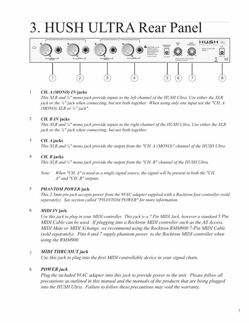
7
CH A (MONO) IN jacksThis XLR and frac14 mono jack provide inputs to the left channel of the HUSH Ultra Use either the XLR jack or the frac14 jack when connecting but not both together When using only one input use the CH A (MONO) XLR or frac14 jack
CH B IN jacksThis XLR and frac14 mono jack provide inputs to the right channel of the HUSH Ultra Use either the XLR jack or the frac14 jack when connecting but not both together
CH A jacksThis XLR and frac14 mono jack provide the output from the CH A (MONO) channel of the HUSH Ultra
CH B jacksThis XLR and frac14 mono jack provide the output from the CH B channel of the HUSH Ultra
Note When CH A is used as a single signal source the signal will be present in both the CH A and CH B outputs
PHANTOM POWER jackThis 25mm pin jack accepts power from the 9VAC adapter supplied with a Rocktron foot controller (sold seperately) See section called PHANTOM POWER for more information
MIDI IN jackUse this jack to plug in your MIDI controller This jack is a 7 Pin MIDI Jack however a standard 5 Pin MIDI Cable can be used If plugging into a Rocktron MIDI controller such as the All Access MIDI Mate or MIDI Xchange we recommend using the Rocktron RMM900 7-Pin MIDI Cable (sold separately) Pins 6 and 7 supply phantom power to the Rocktron MIDI controller when using the RMM900
MIDI THRUOUT jackUse this jack to plug into the first MIDI controllable device in your signal chain
POWER jackPlug the included 9VAC adapter into this jack to provide power to the unit Please follow all precautions as outlined in this manual and the manuals of the products that are being plugged into the HUSH Ultra Failure to follow these precautions may void the warranty
3HUSHULTRARearPanel
1
2
3
4
5
6
7
8
8
The HUSH ULTRA default operation settings are
MIDICHANNE L=OMNI
PROGRAMCHANGE S=ON
PROGRAMMAPPING=OFF
HUSHACTIVE =IN
PROGRAMMING PRESETS
1Choosepresetnumberby turningthePRE SE TFUNCTIONSE LE CTK noboruseMid iController
2Ad justHushthreshold controltoeliminatenoiseand hissby turningtheHUSHTHRE SHOLDPARAME TE RSE LE CTK nob
3Ad justGateThreshold by usingtheGATE THRE SHOLDPARAME TE RSE LE CTknob
Note If you want desired preset to be a True Bypass preset press the Bypass button now
4Pressand releasetheSTORE E DITbuttontosavey ourchanges
5Thed isplay willblinkldquoSTORE ATPRE SE Tldquo
Notetocancelthestoremod eatany timeturnthePARAME TE RADJUSTK NOB
6UsethePRE SE TFUNCTIONSE LE CTknoband pickthed estinationpresetwherey ouwould liketosavey ourchanges
7Pressand releasetheSTORE E DITbutton
You must adjust the Hush Threshold or Gate Threshold in order to use the store function When not in the EDIT mode if you want to store the current changes to the preset the store button must be pressed within 5 seconds after theinitialchangeAfter5secstheHUSHULTRAwillreturntothepresetnamestand by mod eTostorethechangessimply re-adjust either the Hush Threshold or Gate Threshold and press store
HUSH Ultra Quick Start
9
HUSH THRESHOLD CONTROLThe front panel HUSH Threshold control determines the minimum input level at which the HUSH filter and downward expander will begin to operate Setting this control too high will result in a loss of sustain as notes will tend to die out much faster than they should Conversely when set too low the expander will close too late (if at all) and the noise floor will remain audible
GATE THRESHOLD CONTROLThe other half of the HUSH Ultra consists of a noise gate A noise gate completely shuts off the output signal when the input signalleveld ropsbelowaprescribed threshold level(volume)OntheHUSHUltra thisthreshold isd etermined by theGateThreshold control on the front panel This control should be set so that it doesnt cut notes off (ie set too high) yet doesnt activatelongafteranoteend s(allowingthenoisefloortoremainaud ible)
Thiscircuitiscombined withtheVariableIntegrated Release(VIR)circuittoprovid eaninternalvariablereleasetothed ownward expand erWiththeVIRcircuit iftheguitarsignald ecay sslowly thed ownward expand erwillengageslowly Iftheguitarsignalstopsquickly thed ownward expand erwillengagequickly TheLE Dind icateswhend ownward expan-sion is active
HUSHamp GATE THRE SHOLD
10
This connection is an example of a mono connection from a preamp and a multi-effects processor
System Connections
11
This connection is an example of a stereo connection from a stereo preamp and multi-effects processor
System Connections
12
This is a connection example of how you can connect the HUSH Ultra to use with a guitar amp head
System Connections
13
This is a connection example of how you can connect the HUSH Ultra to use with a guitar amp combo
System Connections
14
When used properly the HUSH Ultra should be completely transparent (ie it should not effect the audio signalmdashonly the noise) To maximize the performance of the HUSH Ultra it is necessary to understand its front panel controls and how they work together By understanding how these controls work it will be easier to cor-rectly set up the HUSH Ultra to suit any application
The HUSH Ultra front panel provides two controls which each manipulate both channels simultaneously The HUSH Threshold control sets the amount of noise reduction required for a given input signal while the Gate Threshold control provides additional downward expansion when increased (The Gate Threshold con-trol may also be used by itself allowing the unit to be used as strictly a downward expander)
HUSHreg Section
Rocktrons patented HUSH noise reduction is a single-ended system that com-bines the principles of dynamic filtering and low-level downward expansion
Dynamic Filtering
Dynamic filtering is achieved by dynamically-controlling a low pass filter to open and close the bandwidth of the output signal depending upon the amount of mid and high band information present in the input signal The filter bandwidth will only open far enough to pass the highest frequency information in the input signal thus reducing the noise above it
For example if the highest frequency present in the input signal is 8kHz the filter will open to pass up to 8kHz while the noise from 8kHz to 20kHz would be reduced If a signal with frequency components up to 20kHz appears at the input the dynamic filter will open to its full extreme (40kHz)
HUSH Description
15
As the input signal drops further below the threshold point downward expansion increases A drop in the input level by 20dB would cause the output level to drop approximately 40dB (ie 20dB of gain reduction) In the absence of any input signal the expander will reduce the gain so that the noise floor becomes inaudible
This means that if a signal is present at the input which consists of primar-ily bass components the dynamic filter will reduce mid or high band noise If no mid or high band information is present the filter will close down to a pre-set cut-off point of 1kHz (allowing only frequencies of 1kHz and below to pass) However if the input signal has high frequency components present the dynamic filter will open fully to pass the signal and eliminate the possibility of a loss of high end frequency response
Downward Expansion
The second half of the HUSH process incorporates downward expansion The low level expander of the HUSH system operates like an electronic volume controlTheHUSHsy stemutilizesavoltage-controlled amplifier (VCA)circuitwhich can control the gain between the input and the output from unity to 30 40 or even 50dB of gain reduction When the input signal is above the user pre-set threshold point theVCAcircuit remainsatunity gain (Thismeans that theoutput signal level is equal to the input signal level) As the input signal level drops below the user preset threshold point downward expansion begins It is at this point that the expander acts like an electronic volume control and gradually begins to decrease the output signal level relative to the input signal level
16
E achHUSHUltrapreset isd ivid ed up into ind ivid ualblockscalled FUNCTIONS (suchasGlobal TrueBy pass HUSH ChannelLink TitleE d it MIDIDumpLoad and GlobalRestore)Within each function of each configuration is a set of controls which allow you to manipulate vari-ous aspects of that function These controls are called PARAMETERS It is the setting of each of the parameters which determines the overall soundaction of each preset
Toaccess theseFUNCTIONSand PARAME TE RS y oumust first enter into the E DITMODE
TheHUSHUltra is setup toallowy ou to first accesseach function (via theFUNCTIONSE LE CTknob) then theparameter list foreach function (via thePARAME TE RSE LE CTknob)and finally thead justablevalue foreachparameter (via thePARAME TE RADJUSTknob)
The functions available for each preset are dependent upon which effect is currently recalled The remainder of this section will describe each of the effect-based functions and the associated adjustable parameters they provide
The remaining functions are utility-based and are described in the section titled Operating the HUSH Ultra
Functions and Parameters Descriptions
Edit Mode
17
TITLE EDIT Function
The Title Edit function allows you to create a unique name for your preset The Parameter select knob is used to move the cursor The Parameter adjust knob is used to change the character in the title
TITLE EDIT
PARAME TE RSE LE CT=CHARACTE RPOSITION
PARAME TE RADJUST=CHARACTE RSE LE CT
IMPORTANTWheny ouhavecompleted ed itingtheTITLE y oumustexecuteSTORE beforeleavingtheTITLE EDIT function
Thenext functiond isplay ed after turning theFUNCTIONSE LE CTknob is the True-By passfunction
The PARAMETER SELECT knob will allow you to access these Global parameters
TRUE BYPASS Function
ThisTBYPASSparameterallowsy ou to select either ONor OFF WhenON theTrueBy pass is activeand the signalpassesd irectly through theHUSHUltraunaffected WhenOFF is selected theunit is activeand TrueBy pass isoff and HUSH is active
TBYPASS
TRUE BYPASSuseshighquality relay stoperformatotalby passoftheHUSHULTRAwhenus-ing the frac14 jacks
Thismay beactivated intheE DITMODE orviatheTRUE BYPASSbuttononthefrontpanelind icated asINOUTonthefrontoftheHUSHUltraWhenTRUE BYPASSisontheGreenLE Dwillbelit
True bypass state will be stored into the preset
TRUE BYPASS
TBYPASS OFFON TBYPASSMCC OFF120 MCCassigned toTBYPASS
Note TBYPASS MCC is programmable per preset
18
HUSHreg Function
TheHUSHIOparameter simply d etermineswhether theHUSHreg circuit is activefor thecurrentpreset WhenIN is selected theHUSH isactive WhenOUTis selected theHUSH is OFF
TheE XPTHRE SHOLD(E xpand erThreshold )parameterd etermines the levelatwhichd ownward expansionbeginsForexample if theE XPTHRE SHOLDwasset at -20(dB) and the input signal dropped below -20(dB) downward expansion would begin
TheGATE THRE SHOLDhiscontrol isused tod etermine the levelatwhich thegate will begin to operate As the input signal drops below this level the gate will activate and downward expansion will begin
HUSH IO
EXPTHRESH1
GATETHRESH1
HUSH INOUTHUSH_ THRSH_A 1 64GATE_ THRSH_A 1 64 HUSH_ THRSH_B 1 64 GATE_ THRSH_B 1 64 HUSH_ THRSH_C 1 64 GATE_ THRSH_C 1 64 HUSH_ THRSH_D 1 64 GATE_ THRSH_D 1 64
Only used whenMIDIMCCLINK isactive
19
Theparametersprovid ed in this functionaffectALLpresets (ie the settings stored for theseparametersare the same for all presets)
The PARAMETER SELECT knob will allow you to access these Global parameters
GLOBAL Function
TheHUSHOFFSE Tparameterallowsy ou toglobally (allpresets) ad just theHUSHreg Ex-pander Threshold This means that if this parameter is altered from 0(dB) to +3(dB) the Expander Threshold will be 3dB higher for all presets This feature can be useful when switching from a quiet guitar with passive electronics to a noisy guitar with active elec-tronics as the active guitar would require a higher Threshold level in all presets
MIDIRE CE IVE CHANNE L-116OMIThed efault setting isOMNI
ThePROGRAMCHANGE Sfunctionallowsy ou toglobally turnONOFF theHUSHUl-tra toacceptProgramChanges fromotherd evices Thed efault setting isON
ThePRE SE TMAPfunctionallowsy ou toglobally turnONOFF thePRE SE TMAPPINGfunction The preset mapping allows the HUSH Ultra to receive a Program Change from a MIDI Controller for one preset but to actually recall a different preset See PRESET MAPPING section later in this manual for more detailed information on PRESET MAP-PING
TheCHNLINK ldquoONOFFrdquod etermineswhethertheCHNLINK FunctionisactiveorldquoONrdquoornotactiveorldquoOFFrdquo
CONTINUOUSCONTROLLE RNUMBE R
E XPANDE RTHRE SHOLD1parameterd eterminesthelevelatwhichd ownward expansionbeginsForexample iftheE XPTHRE SHOLDwassetat-20(d B)and the input signal dropped below -20(dB) downward expansion would begin
GATE THRE SHOLD1controlisused tod eterminethelevelatwhichthegatewillbegin to operate As the input signal drops below this level the gate will activate and downward expansion will begin
E XPANDE RTHRE SHOLD2parameterd eterminesthelevelatwhichd ownward expansionbeginsForexample iftheE XPTHRE SHOLD2wassetat-20(d B)and the input signal dropped below -20(dB) downward expansion would begin Note thatthisisonly used withtheMIDIMCCLinkisactive
GATE THRE SHOLD2controlisused tod eterminethelevelatwhichthegatewillbegin to operate As the input signal drops below this level the gate will activate and downward expansion will begin Note that this is only used with the MIDI MCCLinkisactive
E XPANDE RTHRE SHOLD3parameterd eterminesthelevelatwhichd ownward expansionbeginsForexample iftheE XPTHRE SHOLD3wassetat-20(d B)and the input signal dropped below -20(dB) downward expansion would begin Note thatthisisonly used withtheMIDIMCCLinkisactive
HUSH OFFSET
MIDI RX
PROGRAM CHANGES
PRESET MAP
CHNLINK
CC_NUM
EXP THRESH1
GATE THRESH1
EXP THRESH2
GATE THRESH2
EXP THRESH3
20
GATE THRE SHOLD3controlisused tod eterminethelevelatwhichthegatewillbegin to operate As the input signal drops below this level the gate will activate and downward expansion will begin Note that this is only used with the MIDI MCCLinkisactive
E XPANDE RTHRE SHOLD4parameterd eterminesthelevelatwhichd ownward expansionbeginsForexample iftheE XPTHRE SHOLD4wassetat-20(d B)and the input signal dropped below -20(dB) downward expansion would begin Note thatthisisonly used withtheMIDIMCCLinkisactive
GATE THRE SHOLD4controlisused tod eterminethelevelatwhichthegatewillbegin to operate As the input signal drops below this level the gate will activate and downward expansion will begin Note that this is only used with the MIDI MCCLinkisactive
GATE THRESH3
EXP THRESH4
GATE THRESH4
GLOBAL Function continued
21
MIDI CTRLINK
For most users using individual presets will cover your needs however there are some power users that may desire to consider the following Ify ouhavea4channelamplifierthaty oucanuse4controllerstochangechannelsy oucanprogram1presetusingtheMCCLINK
CTRLINK OFFDetermineswhetherfunctionisactive
CC_NUM_AOFF120Assignscontrollernumber
This correlates to recall HUSH_ THRSH_A and HUSH_ GATE_A when determined that the control-ler assigned matches and that a value greater than 63 has been detected as the channel select valueThis will function with latching and momentary switching
DE FAULTMCCCC_NUM_A will map to HUSH_ THRSH_A and HUSH_ GATE_A parameters 85CC_NUM_B will map to HUSH_ THRSH_B and HUSH_ GATE_B parameters 86CC_NUM_C will map to HUSH_ THRSH_C and HUSH_ GATE_C parameters 87CC_NUM_D will map to HUSH_ THRSH_D and HUSH_ GATE_D parameters 88TBYPASS MCC controller to be used for TRUE BYPASS 89
NoteItisrecommend ed thatPROGRAMCHANGE SintheGLOBALFUNCTIONissettooffwhenusingtheMCCLINK mod eMCCLINK isprogrammableperpresetifacombinationofpro-gramchangesand theMCCLINK isd esired WhentheCTRLINK isonand y ouareoutoftheE DITMODE and y ouhavesentany ofthemapped controllerstotheHushUltratheHushThreshold and Gate Threshold controls will automatically map to the appropriate selection HUSH_ THRSH_A B C or D Example A Midi controller sends MCC 87 with a value of 127 when you adjust the Hush Threshold y ouwillseeHUSH_THRSH_Conthed isplay ThustheHUSHULTRAknowsthatsetCis currently being used
22
PRESET MAPPING Function
The Preset Mapping function allows you to use a MIDI Controller to recall different presets via program changes
MIDIRE CE IVE DPROGRAMCHANGE number ison the left sid eof the screen
The PRESET that will be recalled is on the right side of the screen
NotePRE SE TMAP in theGLOBALFUNCTIONmustbe set toONformappingto be active
PRESET MAPPING
MIDI DUMPLOAD Function
This function allows you to dump 1 preset from one HUSH Ultra to a second HUSH Ultra or a MIDI sequencer device
This functionallowsy ou tod umpALLpresets fromoneHUSHUltra toasecond HUSH Ultra or MIDI sequencer device
1 PR DUMPLOAD
BULK DUMPLOAD
23
FUNCTION PARAMETER LIST RANGE(viaFUNCTIONSE LE CT) (viaPARAME TE RSE LE CT) (viaPARAME TE RADJUST)
TITLE E DIT XXXXXXXXX
TRUE BYPASS TBYPASS OFF ON
HUSH HUSH(HushInOut) Out In E XPTHRE SH1(E xpand erThreshold Level) 164 GATE THRSH1(GateThreshold Level) 164
GLOBAL HUSHOFFSE T -10(d B)to+30(d B) MIDIRE CV 116 OMNI PROGRAMCHANGE S OFFON PRE SE TMAP OFFON CTRLINK OFFON CC_NUM_A 0TO120 CC_NUM_B 0TO120 CC_NUM_C 0TO120 CC_NUM_D 0TO120 TBYPASSMCC 0TO120 E XPTHRSH1(E xpand erThreshold Level) 164 GATE THRSH1(GateThreshold Level) 164 E XPTHRSH2(E xpand erThreshold Level) 164 GATE THRSH2(GateThreshold Level) 164 E XPTHRSH3(E xpand erThreshold Level) 164 GATE THRSH3(GateThreshold Level) 164 E XPTHRSH4(E xpand erThreshold Level) 164 GATE THRSH4(GateThreshold Level) 164
PRESET MAPPING 1MAPTO1 2MAPTO2 etc
MIDIDUMPLOAD 1PRDUMPLOAD BULK DUMPLOAD
VE RSIONNUMBE R XXXXXXXXX
Function Parameter Range Listing
24
Operating the HUSH Ultra
Top line of display will showPRESET NUMBER - Displays the Preset Number you have selected PRE SE TTITLE -ThisistheNAME ofthepreset-intheexamplebelow-USE R1
Display Description
TheLCDd isplay ontheHUSHUltraprovid esy ouwiththeinformationaboutthepresety ouarein
1 u s e r 1
PRESET NAMEPRESET NUMBER
The HUSH Ultra provides 128 stored presets Any of the 128 presets can be called up at any time via the PRESET knob or via a MIDI Controller
Each preset has the following Functions available at all times
TITLE E DITTRUE BYPASS HUSHreg GLOBALMIDICTRLINK PRESET MAPPING MIDIDUMPLOADVE RSIONNUMBE R
25
SELECTING A PRESET
1
There are two ways to select a preset on the HUSH Ultra You can either turn the PRESET knob to the desired preset you wish to recall The display will show the selected preset number
Thesecond way toselectapresetwithaMIDIControllersuchastheRocktronMIDIXchange MIDIMate AllAccessorAllAccessLTDSeesectiononMIDIConnectiononhowtoconnectaMIDIPed alto the HUSH Ultra and follow all instructions that come with your MIDI Pedal
1 u s e r 1
1 Turn the preset select knob to the desired preset
2 u s e r 2
26
NOTE Ify ouhavechanged aparametertheSTORE LE DwilllightThechange(s)thaty oumad ewillnotbestored untily ouhavepressed theSTORE buttonPleasefollowinstructionsonthenextpage for details on how to store changed parameters
CHANGING PRESET PARAMETERS
M I D I R X O M N I
G L O B A L
STE P1-E nterE DITMODE by pressingtheSTORE E DITbuttonasshownaboveWheninE DITMODE thed isplay willshowy ouareinE DITMODE onthetopline
STE P2-ToaccessthefirstFUNCTIONtobead justed turnthePRE SE TFUNCTIONSE LE CTknob The display will then show
G L O B A L
E D I T M O D E
STE P3-ToaccessthefirstPARAME TE Rtobead justed turntheGATE THRE SHOLDPARAM-E TE RSE LE CTknobThed isplay willthenshow
M I D I R X 1 6
G L O B A L
STE P4-Toad justtheselected PARAME TE R turntheHUSHTHRE SHOLDPARAME TE RAD-JUSTknobThed isplay willthenshowthead justed parameter
27
STORING CHANGED PRESET PARAMETERS
Whileviewingafunctionorparametertitle presstheSTORE buttontostartthestoreproced ureTheword sSTORE ATPRE SE Twillnowbeflashingund erthechanged presetnameasshownbelowIfy ouwould liketostorethechangesmad eatthecurrentpreset simply presstheSTORE E DITbut-tonagainand thechangeswillbestored Theword STORE Dwillflashonceand thepresetwillbestored
If you like to store the changes made at a different preset number while viewing a function or parameter title presstheSTORE buttontostartthestoreproced ureTheword sSTORE ATPRE SE Twillnowbeflashingund erthechanged presetnameNextturnthePRE SE TSE LE CTknobtothed esired presetnumberand presstheSTORE E DITbuttonTheword STORE Dwillflashonceand thepresetwillbestored at the selected preset
1 u s e R 1
S T O R E A T P R E S E T
2 U S E R 1
S T O R E A T P R E S E T
1 u s e R 1
S T O R E A T P R E S E T
1 u s e R 1
S T O R E d
1 u s e R 1
2 u s e R 1
STORE CHANGES AT THE SAME PRESET
STORE CHANGES AT A NEW PRESET
28
TobegintheTitleE d itfunction turntheFUNCTIONSE LE CTknobclockwiseuntiltheHUSHUltrad isplay sTITLE E DIT
Step 1
TurnthePARAME TE RSE LE CTknobclockwisetoinitiatetheTitleE d itmod eTurning this knob will also select the character above the part of the current title to be ed ited Thelettertobead justed willhaveaflashingboxoverthecharacterselected
Step 2
UsethePARAME TE RADJUSTknobtoselectthed esired characterforthecurrentposition(flashingbox)
Step 3
t i t l e e d i t
t i t l e e d i t
1 U s e r 1 8
(Flashing box)
Title Edit
Character to be changed
t i t l e e d i t
1 h U s e r 1 8
(Flashing box)
Character to be changed
29
Toed itthenextcharacterinthenextposition turnthePARAME TE RSE LE CTknobonestepclockwiseTheflashingboxwillmovetothenextcharactertobead justed
Step 4
NOTE The STORE button must be pressed to save the new title Exiting the Title Edit func-tion before pressing the STORE button will erase any editing that was done in Title Edit Also after flashing STORED the HUSH Ultra will exit the title edit mode and return to the main preset number
After all the characters have been edited as needed press the STORE button to save the new title to memory The HUSH Ultra will flash STORED briefly
Step 5
Title Edit continued
t i t l e e d i t
1 h u U s e r 1 8
(Flashing box)
Character to be changed
1 h u s h u l t r a
30
NowthePARAME TE RSE LE CTcorrelatestotheMIDIRE CE IVE DPRO-GRAM CHANGE number (number on the left side of screen)
ThePARAME TE RADJUSTselectsthePRE SE Tthatwillberecalled (Numberon the right side of the screen) when the received program change is executed
InaboveexampletheHUSHULTRAreceived aPROGRAMCHANGE fromamidi controller for preset 1 The actual preset recalled will be 15
NotePRE SE TMAPintheGLOBALFUNCTIONmustbesettoONformap-ping to be active
IMPORTANT
Aftery ouhavecompleted ally ourpresetmappingy oumustexecuteSTORE before leaving the PRESET MAPPING function
PRESET MAPPING Function
Step 2
Step 3
Step 1 UseFUNCTIONSE LE CTwhileinE DITMODE toselectthePRE SE TMAP-PING function
TurnthePARAME TE RSE LE CTtoentertheMAPPINGMODE
P R E S E T M A P P I N G
P R E S E T M A P P I N G
1 M A P T O 1 5
31
Any or all of the HUSH Ultras presets may be dumped to another HUSH Ultra a sequencer or MIDI utility programusingaPCmid iinterfacetocreatea(sy x)fileAlltheinformationaboutthepresetsyou have created will be dumped consisting of parameter values title characters and controller assign-ments When dumping a single preset into another HUSH Ultra the dumped preset can be loaded into any preset location on the receiving unit
Note The HUSH Ultra midi data when sent by external means such as a PC MIDI utility program you willneed toconfigureitasstated below
Buffer size 264 bytesNoofbuffers16bothRXand TX100ms between buffers be used initially as a starting point100ms after F7 [ optional ]
If a MIDI sequencer is used to store the data record the Sysex data in real-time or adhere to the param-eters given above
MIDI DUMPLOAD
Step 2
Step 3
M I D I D U M P L O A D
Step 1 Connectastand ard MIDIcablefromtheMIDIOUTofthetransmittingHUSHUltrato the MIDI IN of the receiving HUSH Ultra Consult MIDI Connection drawing for more information
If you are dumping a single preset to another HUSH Ultra the transmitting HUSH Ultra must have that preset selected
PresstheSTORE E DITbuttontoenterintotheE DITMODE TurntheFUNC-TIONSE LE CTknobtoMIDIDUMPLOAD
Step 4 OnthereceivingHUSHUltrausethePRE SE TSelectcontroltoselectthepresetlocation where the received preset will be stored Note that the preset currently stored at the selected location will be lost when the new preset is received
32
Step 6 ToBULK DUMPallpresetstoanotherHUSHUltraorupload themtoaSequenceror Computer using a PC MIDI interface along with a MIDI Utility program use thePARAME TE RSE LE CTknob selectBULK DUMPLOADand followSteps4and 5
Step 5 OnthetransmittingHUSHUltra presstheSTORE buttontod umpthepresetThetransmitting HUSH Ultra will display DUMPED
M I D I D U M P L O A D
1 d u m p e d
M I D I D U M P L O A D
b u l k d u m p l o a d
MIDI DUMPLOAD continued
33
The MIDI IN in the HUSH Ultra will allow you to select presets directly from a MIDI controller such astheRocktronMIDIXChange MIDIMate AllAccessorAllAccessLTDFollowtheconnectionstepsintheCONNE CTIONSsectionofthismanual
Please note that though the HUSH Ultra has a 7 Pin din connector any standard 5 pin MIDI cord may be used ford eviceconnectionsThis7-pinDINconnectormustbeconnected totheMIDIOUTjackofthetransmitting MIDI device via a standard MIDI cable or to the MIDI THRU jack of the preceding MIDI device (if the HUSH Ultra is within a chain of MIDI devices) Pins 6 and 7 of this connector carry phantompowertopoweraRocktronMIDIfootcontroller(MIDIXChange AllAccessand MIDIMate)when a 7-pin MIDI cable is used
MIDI IN
TheMIDIOUTTHRUintheHUSHUltrawillallowy outotransmitand controlotherMIDIcapabled evicesthrutheHUSHUltraFollowtheconnectionstepsintheCONNE CTIONSSE CTIONofthismanualFollowtheconnectionstepsintheCONNE CTIONSsectionofthismanual
This standard 5-pin DIN connector can be connected to the MIDI IN jack of another device via a stan-dard MIDI cable There are limitations to the number of devices that can be chained (or series connect-ed) in this fashion
Note Inherently in MIDI there is a limit to the number of devices which can be chained together (con-nected in series) With more than 3 devices a slight distortion of the MIDI signal can occur (due to signal degradation) which can cause an error in MIDI signal transmission Should this problem arise a MIDI Thru box can be used which connects directly to the MIDI device which transmits MIDI infor-mation and has multiple connectors for the multiple devices receiving MIDI MIDI cables should not exceed 50 feet (15 meters) in length
MIDI OUTTHRU
34
This 25mm PIN jack offers the ability to power Rocktron MIDI foot controllers from a 7-pin MIDI cable which connects from the Rocktron MIDI foot controller to the MIDI IN jack on the rear panel of HUSH Ultra
Thiseliminatestheneed tofind anACoutletnearwherethefootped alwould beplaced d uringaperformance or the need to run an extension cord out to the footswitch Instead of inserting the AC ad aptorintotheldquoPOWE Rrdquojackofthefootswitchasy ouwould normally plugitintotheldquoPHAN-TOMPOWE RrdquojackontheHUSHUltraThiswillpowertheRocktronMIDIfootcontrollerthroughpins 6 and 7 of the MIDI cable connecting the two units The Rocktron RMM900 7-pin MIDI cable must be used in this operation and is available from your Rocktron dealer
PHANTOM POWER
35
+15dB (+4 Ref)+5dB (-10dB Ref)
470K Ohms
100Ohms
10kOhms
22kOhms
up to 72dB
plusmn5dB 10Hz - 27kHz
105dB
-100dBu
041 0dBu 1kHz (typ)
405mA
19 x 4 x 1frac34
9vac 2000mA
Maximum Input Level
Input Impedance 14 Jacks
Output Impedance 14 Jacks
Input Impedance XLR Jacks
Output Impedance XLR Jacks
Effective Noise Reduction
Frequency Response
Dynamic Range
Noise Floor
THD + Noise
Current Consumption
Dimensions
Power
Specifications
Note 0dBv = 0775V RMSCE Approved
36
37
38
Rocktron -A Division of GHS Corporation2813 Wilbur AvenueBattle Creek MI 49037USARocktron Phone 1-(269)-968-3351Email inforocktroncom
wwwrocktroncom
2013-0012Rev 12513
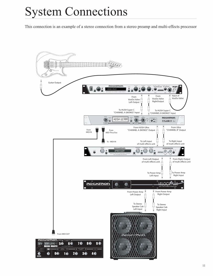
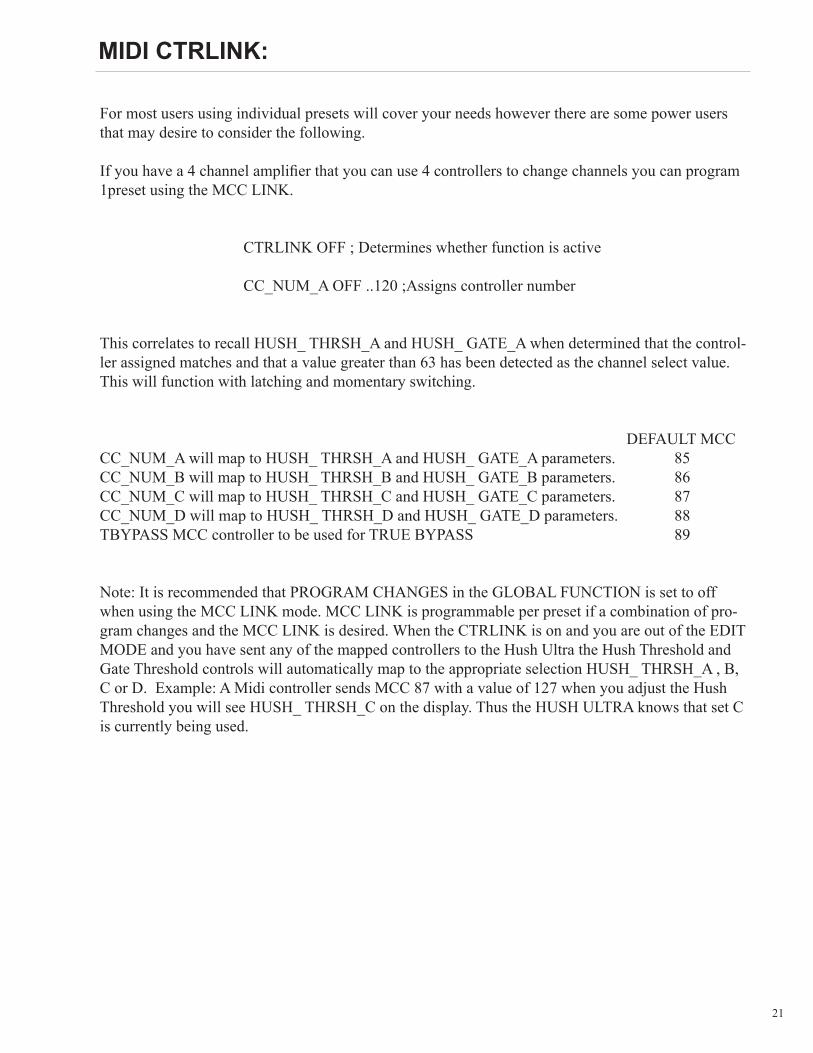

36
37
38
Rocktron -A Division of GHS Corporation2813 Wilbur AvenueBattle Creek MI 49037USARocktron Phone 1-(269)-968-3351Email inforocktroncom
wwwrocktroncom
2013-0012Rev 12513

37
38
Rocktron -A Division of GHS Corporation2813 Wilbur AvenueBattle Creek MI 49037USARocktron Phone 1-(269)-968-3351Email inforocktroncom
wwwrocktroncom
2013-0012Rev 12513

38
Rocktron -A Division of GHS Corporation2813 Wilbur AvenueBattle Creek MI 49037USARocktron Phone 1-(269)-968-3351Email inforocktroncom
wwwrocktroncom
2013-0012Rev 12513