instruction manual · 5 introduction notes on warranty the terms of the sales contract apply....
TRANSCRIPT

Instruction Manual
Hakomatic 1800 V/LPG (7574.10/20)
Instruction Manual
Hakomatic 1800 V/LPG (7574.10/20)
2
Table of Content
1 Safety information . . . . . . . . 6
1.1 Safety and Warning Symbols. 61.2 General Provisions. . . . . . . . . 71.3 Provisions for Operation. . . . . 71.4 Maintenance Instructions . . . . 81.5 Specific Hazards . . . . . . . . . . 91.6 Instructions for Protection of En-
vironment . . . . . . . . . . . . . . . 111.7 Labels at the Machine . . . . . 12
2 First Operation . . . . . . . . . . 14
2.1 Instruction. . . . . . . . . . . . . . . 142.2 Before First Operation . . . . . 142.3 Start Vehicle. . . . . . . . . . . . . 142.4 Slow Down and Stop . . . . . . 152.5 Riding Up- and Downhill. . . . 152.6 Work with the Machine. . . . . 152.7 After Work . . . . . . . . . . . . . . 152.9 Tie-down points . . . . . . . . . . 162.10 Towing . . . . . . . . . . . . . . . . . 162.11 Support Points . . . . . . . . . . . 16
3 Operation . . . . . . . . . . . . . . 17
3.1 Method of Operation . . . . . . 173.1.1 General . . . . . . . . . . . . . . . . 173.1.2 Sweeping Unit . . . . . . . . . . . 173.1.3 Water Tank. . . . . . . . . . . . . . 173.1.4 Scrubbing Unit . . . . . . . . . . . 183.1.5 Squeegee. . . . . . . . . . . . . . . 183.1.6 Travel Drive and Work Hydrau-
lics . . . . . . . . . . . . . . . . . . . . 183.1.7 Options. . . . . . . . . . . . . . . . . 183.2 Control and Display Ele-
ments . . . . . . . . . . . . . . . . . . 193.2.1 Overview . . . . . . . . . . . . . . . 193.2.2 Main Control Panel. . . . . . . . 213.2.3 Left-hand Control Panel . . . . 253.2.4 Controls of the Machine . . . . 26
4 Technical Data . . . . . . . . . . 29
5 Maintenance and Care . . . . 34
5.1 General . . . . . . . . . . . . . . . . 345.2 Hako System Maintenance . 345.3 Maintenance document . . . . 355.4 Maintenance Schedule. . . . . 355.5.1 Open Engine Frame. . . . . . . 435.5.2 Refill Engine Oil . . . . . . . . . . 435.5.3 Change Engine Oil and Oil
Filter . . . . . . . . . . . . . . . . . . . 435.5.4 Change fuel filter . . . . . . . . . 445.6.1 Remove Main Filter . . . . . . . 455.6.2 Clean Main Filter . . . . . . . . . 455.6.3 Install Main Filter . . . . . . . . . 455.6.4 Change Main Filter. . . . . . . . 455.6.5 Change Safety Cartridge . . . 455.6.6 Clean Dust Discharge Valve 455.7.1 Clean Radiator . . . . . . . . . . . 475.7.2 Re-fill Coolant. . . . . . . . . . . . 475.7.3 Change Coolant . . . . . . . . . . 475.8 Liquid Propellant Gas
System . . . . . . . . . . . . . . . . . 485.8.1 Change Liquid Propellant Gas
Tank . . . . . . . . . . . . . . . . . . . 495.8.2 Change liquid propellant gas
tank (option) . . . . . . . . . . . . . 49

3
Table of Content
5.9 Hydraulic System . . . . . . . . . 505.9.1 Re-fill Hydraulic Fluid . . . . . . 515.9.2 Change hydraulic fluid . . . . . 515.9.3 Change hydraulic fluid filter . 515.10 Dirt Hopper . . . . . . . . . . . . . . 525.10.1 Clean Dust Filter. . . . . . . . . . 535.10.2 Change Dust Filter . . . . . . . . 535.10.3 Empty dirt hopper . . . . . . . . . 535.11 Side Brush . . . . . . . . . . . . . . 545.11.1 Adjust Inclination Side
Brushes . . . . . . . . . . . . . . . . 555.11.2 Wearing Compensation of Side
Brushes . . . . . . . . . . . . . . . . 555.11.3 Change Side Brushes . . . . . 555.12 Cylindrical Broom . . . . . . . . . 565.12.1 Adjust Wearing Compensation
of Cylindrical Broom . . . . . . . 575.12.2 Adjust Parallelism of Cylindrical
Broom. . . . . . . . . . . . . . . . . . 575.12.3 Change Cylindrical Broom . . 585.12.4 Change Cylindrical Broom
Apron . . . . . . . . . . . . . . . . . . 585.13 Scrubbing Unit . . . . . . . . . . . 595.13.1 Change Scrubbing Brushes . 605.13.2 Change Seals. . . . . . . . . . . . 605.13.3 Adjust wiper . . . . . . . . . . . . . 60
5.14 Squeegee. . . . . . . . . . . . . . . 615.14.1 Remove Squeegee . . . . . . . 625.14.2 Change Seals. . . . . . . . . . . . 625.14.3 Adjust Squeegee . . . . . . . . . 625.15 Water Supply . . . . . . . . . . . . 635.15.1 Fill Clear Water Tank . . . . . . 645.15.2 Drain Clear Water . . . . . . . . 645.15.3 Clean Clear water filter. . . . . 645.15.4 Empty Soiled Water Tank . . 645.15.5 Clean Soiled Water Tank . . . 645.16 Tyres . . . . . . . . . . . . . . . . . . 655.16.1 Check Tyre Wearing . . . . . . 655.16.2 Remove Tyres . . . . . . . . . . . 655.16.3 Install Tyres . . . . . . . . . . . . . 655.17 Brakes . . . . . . . . . . . . . . . . . 655.18 Electrical System . . . . . . . . . 665.18.1 Change Fuse . . . . . . . . . . . . 665.18.2 Change Battery . . . . . . . . . . 66
Declaration of Conformity. . . 67

4
Introduction
IntroductionDear customer, It is our desire that the good characteristics of the Hakomatic 1800 should justify the confidence you demonstrated by making this purchase.Prior to the first drive, carefully read the chapter "Safety Information” as well, in order to be prepared for possible dan-gerous situations.Your own safety, as well as the safety of others, depends to a great extent on how the vehicle is moved and operated. Therefore, carefully read and under-stand this operation and maintenance manual prior to the first drive.The manual provides valuable informa-tion about operation, service and maintenance. The warning symbols as used in this manual identifies items re-levant to safety. Please observe the safety provisions (see chapter "Safety Information”).Your authorised Hako dealer will be pleased to answer further questions re-garding the vehicle or the operation and maintenance manual.Please be advised explicitly that we cannot accept any legal issues out of the contents of this manual.If repair work has to be performed make
sure that only genuine spare parts are used; only genuine spare parts may guarantee a dependable machine.We reserve the right for technical im-provement..
Valid as of: Mai 2006
Hako GmbHD-23843 Bad OldesloeHamburger Str. 209-239Telefon ++49 (04531) 8060
Proper useThe Hakomatic 1800 is a large-area srubber with integrated sweeping sy-stem for dry and wet cleaning of hard-surfaced floors. Using the machine beyond this scope of application will be deemed improper use; The manufactu-rer cannot be held liable for consequen-tial damages; the user alone bears the risk.The term of proper use also includes operation, maintenance and repair work to be performed in compliance with the manufacturer's specifications. The Hakomatic 1800 may be used by persons only that are familiar with the machine and aware of possible hazards involved.The applicable Accident Prevention Re-gulations, Road Traffic Regulations and further regulations in vigour concerning aspects of safety and working medicine will have to be complied with.If modifications to the machine are made in absence of the manufacturer's prior consent, the latter cannot be held liable for damage resulting from such unauthorized modification.
4
Introduction
IntroductionDear customer, It is our desire that the good characteristics of the Hakomatic 1800 should justify the confidence you demonstrated by making this purchase.Prior to the first drive, carefully read the chapter "Safety Information” as well, in order to be prepared for possible dan-gerous situations.Your own safety, as well as the safety of others, depends to a great extent on how the vehicle is moved and operated. Therefore, carefully read and under-stand this operation and maintenance manual prior to the first drive.The manual provides valuable informa-tion about operation, service and maintenance. The warning symbols as used in this manual identifies items re-levant to safety. Please observe the safety provisions (see chapter "Safety Information”).Your authorised Hako dealer will be pleased to answer further questions re-garding the vehicle or the operation and maintenance manual.Please be advised explicitly that we cannot accept any legal issues out of the contents of this manual.If repair work has to be performed make
sure that only genuine spare parts are used; only genuine spare parts may guarantee a dependable machine.We reserve the right for technical im-provement..
Valid as of: Mai 2006
Hako-Werke GmbHD-23843 Bad OldesloeHamburger Str. 209-239Telefon ++49 (04531) 8060
Proper useThe Hakomatic 1800 is a large-area srubber with integrated sweeping sy-stem for dry and wet cleaning of hard-surfaced floors. Using the machine beyond this scope of application will be deemed improper use; The manufactu-rer cannot be held liable for consequen-tial damages; the user alone bears the risk.The term of proper use also includes operation, maintenance and repair work to be performed in compliance with the manufacturer's specifications. The Hakomatic 1800 may be used by persons only that are familiar with the machine and aware of possible hazards involved.The applicable Accident Prevention Re-gulations, Road Traffic Regulations and further regulations in vigour concerning aspects of safety and working medicine will have to be complied with.If modifications to the machine are made in absence of the manufacturer's prior consent, the latter cannot be held liable for damage resulting from such unauthorized modification.
5
Introduction
Notes on warrantyThe terms of the sales contract apply. Damages are not subject to warranty if they are due to non-compliance with the maintenance and service provisions. The maintenance work has to be perfor-med by an authorized Hako service center and confirmed in the "Mainte-nance certificate" which is the warranty document.The following is excluded from warranty: fuses, natural wear, damages caused by overload, inexpert handling and unauthorized modification of the machine. Moreover, any claim for war-ranty cannot be accepted if damages of the machine are caused by fitting parts or accessories without Hako's prior and explicit consent or by non-compliance with the maintenance instructions.
Acceptance of the machineUpon arrival, check machine for possi-ble damages in transit. For refund of such damage, have the Deutsche Bahn AG or your freight forwarder confirm such damage. Mail notification and waybill to:
Hako GmbHHamburger Strasse 209-23923843 Bad Oldesloe
5
Introduction
Notes on warrantyThe terms of the sales contract apply. Damages are not subject to warranty if they are due to non-compliance with the maintenance and service provisions. The maintenance work has to be perfor-med by an authorized Hako service center and confirmed in the "Mainte-nance certificate" which is the warranty document.The following is excluded from warranty: fuses, natural wear, damages caused by overload, inexpert handling and unauthorized modification of the machine. Moreover, any claim for war-ranty cannot be accepted if damages of the machine are caused by fitting parts or accessories without Hako's prior and explicit consent or by non-compliance with the maintenance instructions.
Acceptance of the machineUpon arrival, check machine for possi-ble damages in transit. For refund of such damage, have the Deutsche Bahn AG or your freight forwarder confirm such damage. Mail notification and waybill to:
Hako-Werke GmbHHamburger Strasse 209-23923843 Bad Oldesloe

6
Safety information
1 Safety information
1.1 Safety and Warning SymbolsAll paragraphs in this manual referring to your personal safety, the safety of your machine and the environment pro-tection are attributed one of the follo-wing warning symbols:
Symbol Hazardous for ... Description
DANGER persons and goods dangerous situationcaused by misuse inaccurate adherence of instruc-tions or prescribed work routine
CAUTION the machine important information on handling the Hakomatic 1800 in order to maintain operability
Ecological hazard the environment due to use of substances representing an inherent danger to health of environment

7
Safety information
1.2 General Provisions• Apart from the provisions contained
in this instruction manual, the gene-ral safety provisions and the acci-dent prevention regulations as imposed by law have to be complied with.
• Before taking your Hakomatic 18000 into operation, carefully read the in-struction manual as well as other se-parate instructions for accessories or attached implements and comply with all points mentioned there du-ring work.
• Persons being trained by qualified Hako technicians only are authori-sed to operate, service and repair the Hakomatic 1800.
• You are advised to thoroughly study the safety instructions since precise knowledge only helps avoiding er-rors during operation of the Hakoma-tic 1800 and thus guarantee faultless usage of the machine.
• The operating instructions have to be at hand at the place of use of the Hakomatic 1800, and therefore have to be kept readily available at the machine.
• When selling or letting the machine
for rent, hand out these documents to the new owner/operator and have the transfer certified!
• The warning and instruction plates attached to the machine contain va-luable advice about safe operation. Immediately replace incomplete or il-legible labels.
• As far as safety standards are con-cerned, spare have to equal genuine spare parts!
• Smoking and handling flames are prohibited during filling fuel tanks and during work at or in the vicinity of fuel-containing components.
• Do not exceed the maximum inclina-tion of 12% for operation rides. Do not exceed the maximum inclination of 16% for transport rides.
• Use only the brushes released by the manufacturer. The use of other brushes can impair the security.
1.3 Provisions for Operation• Before taking into operation, check
the Hakomatic 1800 for operational and traffic safety! Immediately reme-dy malfunctions!
• It is indispensable for the operator to get acquainted with all attached im-plements and controls as well as
with their function before operation begins. Once you have started to work, no time will be left to do so!
• The machine may be used only on such surfaces clearly specified by the owner or his authorised repre-sentative.
• For safety reasons, the driver seat is equipped with a seat contact switch. Bypassing function of the seat con-tact switch is prohibited!
• Do not run engine in closed rooms! Intoxication hazard!
• Never operate the Hakomatic 1800 without operable safety devices in-stalled. (These include in particular the engine fairing door).
• When working with the machine take notice of third persons, especially children.
• Passenger transport is prohibited.• Operate control panel only when
seated.• Never leave the driver's station du-
ring ride!• Use only cleaning agents suitable for
automatic machines (low-foaming) and comply with the instructions for use, disposal and with the warning information specified by the cleaning

8
Safety information
agent's manufacturer.• The Hakomatic 1800 is not designed
for collecting hazardous, inflamma-ble or explosive dusts or substances.
• Usage of the machine in explosive areas is prohibited.
• Do not lift the dirt hopper but directly before disposal; mind sufficient sta-bility.
• Stop the Hakomatic 1800 in work pauses or at the end of shift on solid and even ground and protect it against moving!
• Turn off engine and engage parking brake before leaving the Hakomatic 1800 unattended! Pull ignition key. Never leave the Hakomatic 1800 un-attended if engine is running!
• In order to preclude unauthorised use of the machine switch off machi-ne by pulling the ignition key and clo-sing the gas cylinder valve if required.
• Before transport of the Hakomatic 1800, stop all motors and lower the dirt hopper. Adapt driving habit to lo-cal conditions.
• Always protect the lifted dirt hopper by safety stand.
• Use tool to open the engine hood,
open the lateral cover for mainte-nance purposes only and after standstill of machine.
• Caution - burning parts: a pressure-relief valve is fitted to the radiator.
• Clean dirt hopper and soiled water tank at regular intervals. Recom-mendation: at the end of working day.
• Do not collect burning or glowing ob-ject with the machine.
• To preclude creeping, generally ac-tuate the parking brake when leaving the machine unattended.
• Mind rotating parts when opening the engine compartment.
• Start machine only with all units being off and engine speed switch set to idle position.
1.4 Maintenance Instructions• Observe the maintenance activities
and intervals set out in the instruc-tion manual.
• Have the machine checked for safe condition by an expert at regular in-tervals (recommendation: at least once yearly) as well as after modifi-cations or repair (Check CO-value of the exhaust gas every six months at
least).• Spare parts have to equal the techni-
cal requirements as specified by the manufacturer! Genuine spare parts guarantee compliance with these re-quirements.
• Stop engine before proceeding to in-spection and maintenance work.
• If the Hakomatic 1800 is jacked, have it additionally supported accor-ding to prescriptions.
• Nobody is allowed to stay on a jak-ked or lifted Hakomatic 1800.
• Before working at the tyres, make sure to have the Hakomatic 1800 safely parked and protected against rolling off (blocks). Sufficient know-ledge and appropriate mounting tools are required for mounting tyres.
9
Safety information
• Do not clean the electrical parts by means of high-pressure cleaning equipment.
• Do not proceed to welding, boring, sewing and grinding of the frame and parts of it. A qualified Hako work-shop only is authorised to replace damaged parts.
• Handle battery acid with utmost care - caustic
• Before proceeding to electro-welding at the Hakomatic 1800 disconnect battery.
• Fluids such as fuel or hydraulic oil escaping under high pressure and penetrating the skin may cause se-vere injuries. Immediately contact a doctor to preclude infections.
• Proceed to draining of hot oil with ut-most care - burning hazard.
• Check function of steering and bra-kes before daily work and at a safe place.
• Submit brake systems to thorough inspection at regular intervals! Quali-fied Hako workshops only are autho-rised to proceed to setting and repair works at the brake system.
• Check hydraulic lines at regular in-tervals. Qualified Hako workshops only are authorised to proceed to re-pair works at the hydraulic system.
1.5 Specific HazardsLiquid propellant gas system (LPG)• Apart from the safety provisions con-
tained in the instruction manual for the machine and the accident pre-vention regulation BGV D 34 directi-ve Handling of LPG, the following safety provisions have to be com-plied with:
• Scrubber-driers may be operated only by appropriate persons who have been trained in operating and in handling LPG systems, who have testified their capability to the owner of the unit or his authorised repre-sentative, and who have been orde-red explicitly by him to operate the machine.
• Use the LPG system only if it is in proper condition.
• Only use replacement cylinder ac-cording to labelling i.e. collar ope-ning pointing down because of discharge from liquid phase.
• Discharge from liquid phase by e.g.
overturning the collar opening is not admitted.
• The operator has to use the machine within its design limits and has to take notice of local conditions during riding.
• Change the LPG reservoir after standstill of engine only.
• Smoking and handling open flames are prohibited during change of gas reservoir. Operate machine from one gas reservoir only! Connecting re-servoirs is prohibited. Use blind plug to close unused reservoir ports.
• If stored in garages or halls, do not park the vehicle in direct vicinity of heating elements. When parking the vehicle immediately close discharge valves of the tanks and ride until li-nes are empty.
• Gas cylinder change in garages or below ground level is prohibited.Check the gas system for leakage at regular intervals. Provide for safe placement of vehicles equipped with LPG systems (e.g. provide for suf-ficient ventilation; park above ground level; keep clear of openings, pits, wells and other; close outlet valve).
• According to § 33, 37 of BGV D 34

10
Safety information
directive, vehicles equipped with LPG systems have to be inspected by an expert for safe condition at re-gular intervals, at least once yearly.
• The exhaust gas has to be checked for its contents of contaminants at half-yearly intervals and has to be set to a maximum CO content of 0.1 percent by volume with warm engine at idling speed. Document the resul-ts in a test certificate according to BGV D 34.
• Only experts and qualified personnel is authorised to work at the gas sy-stem.
• When fitting or replacing parts of the gas system, only use parts approved by the manufacturer.
• After repair work and modifications having an influence on operational safety as well as after interruption periods of more than a year, check the LPG system for proper condition, function or leakage.
• Sweepers which are equipped with liquid propellant gas system must not be parked in the vicinity of heat sources; this includes e.g. exposure to strong insolation.
• Have LPG systems checked for pro-
per condition, function or leakage at regular intervals.
Elektric system• Only use genuine fuses with prescri-
bed connecting load!• In case of malfunctions of the electric
system, immediately shutdown ve-hicle and remedy!
• Qualified personnel only is authori-sed to proceed to works at the elec-tric equipment and only according to electro-technical rules!
• Inspect/check the electrical equip-ment of the vehicle at regular inter-vals. Immediately remedy defects such as e.g. loose connections or scorched cables.
• Generally disconnect the battery earth strap before working at the electric system or before welding!
• If improperly executed, starting by means of jumper cable may be dan-gerous. Observe safety provisions for batteries!
Hydraulic system• Qualified Hako workshops only are
authorised to proceed to works at the hydraulic system of the vehicle!
• Check all lines, hoses and screwed connections for leakage and visible
damages in regular intervals! Have such damages and leakages reme-died by return! Leaking oil may cau-se injuries and fire!
• Wear ear protection if required!Oil, grease and other chemical sub-stances• Comply with the safety provisions
applicable for the product (safety leaflet) when handling oil, grease and other chemical substances (bat-tery acid — sulphuric acid)!
• Utmost care is advised when hand-ling hot operating and auxiliary me-dia – Burning hazard!
Battery• Observe the specific safety provisi-
ons and accident prevention regula-tions when handling batteries. Batteries contain sulphuric acid – Caustic!
• During the charging procedure in particular but as well during normal use of batteries, an air-hydrogen mixture is formed in the cells – Ex-plosion hazard! Provide for sufficient ventilation.
• Do not try to start engine by means of jumper cable in case of insufficient electrolyte level; the battery may ex-

11
Safety information
plodeTyres• Qualified personnel or qualified
workshops only are authorised to proceed to repair work at tyres and rims!
• Damaged tyres and/or insufficient in-flation pressure of tyres significantly reduce operational safety of the ve-hicle. Check tyres for prescribed in-flation pressure or damages at regular intervals.
• Do not inflate tyres by combustible gas – Explosion hazard!
Total weight• Respect the admissible total weight,
see technical data.
1.6 Instructions for Protection of Environment
• For safe use of substances inheriting a danger to health and environment such as e.g. oil, detergent, lubrica-ting grease and other, specific know-ledge is required.
• Substances such as oil, grease, de-tergent, paint etc. have to be stored in appropriate reservoirs and treated in compliance with the safety instruc-tions issued by the manufacturer but
never on the Hakomatic 1800.• During maintenance and repair work
and oil changes, collect all operating media in appropriate reservoirs and provide for disposal according to the Waste Recycling and Disposal Act and Used Oil Regulations.
• Leaking oil and lubricant must not get into the soil. Danger of ground-water contamination!
• Immediately wipe away spilled sub-stances and provide for disposal in compliance with the regulations. De-pending on the filtered substances, used filter elements have to be dis-posed of as special waste. Batteries contain caustic sulphuric acid. Ut-most care is advised for handling batteries. Used batteries have to be disposed of as hazardous waste.

12
Safety information
1.7 Labels at the MachineThe following safety and information la-bels are legibly attached to the vehicle. Replace missing or illegible labels im-mediately.
Hako nameplate (Fig. 1/1)
Vehicle identification number (Fig. 1/2)
Instruction manual (Fig. 1/3)
High-pressure cleaner (Fig. 1/4)
Rotating parts at the left/right side of the radiator and at the suction fan of the sweeping und the suction unit (Fig. 1/5)
Pinching hazard: Use safety stand with an opened dirt hopper! (Fig. 1/6)
Burning hazard: Caution inside the en-
gine compartment. Burning hazard! En-gine has not yet cooled down! (Fig. 1/7)
Liquid discharge only! (Fig. 1/8)
For all works at the engine: fully open side door (Fig. 1/9)
After all works at the engine: re-mount fixing plate! (Fig. 1/10)
Hydraulic tank: Do not fill fuel oil or other inflammable or combustible sub-stances! (Fig. 1/11)
Caution - Explosion hazard! (Fig. 1/12)
Caution - Lifted-up disposal! (Fig. 1/13)
USA

13
Safety information
Fig.1 shows LPG variant
11
2 3
5
56 711
412 9 108 13 13
13
Safety information
Fig.1 shows LPG variant
11
2 3
5
56 711
412 9 108 13 13

14
First Operation
2 First Operation
2.1 InstructionInstruction is required before first ope-ration.First instruction into handling of the Ha-komatic 1800 must be held by a quali-fied person sent by your local Hako contract dealer.Your Hako dealer will be informed by the manufacturer upon delivery of the vehicle and will contact you to make a date for instruction.
2.2 Before First OperationProceed to the following controls before first operation of the Hakomatic 1800:1. Re-fill fuel tank of fuel variant. Check
liquid propellant gas level of LPG va-riant. Replace liquid gas tank, see Maintenance chapter.
2. Check engine oil level by means of dipstick. Refill engine oil, see chap-ter Maintenance.
3. Check hydraulic fluid level by means of dipstick. Refill fluid, see chapter Maintenance.
4. Check coolant level. Refill coolant, see chapter Maintenance.
5. Check brake system.6. Check steering.
7. Check lighting, see chapter Operati-on.
8. Check parking surface for signs of leakage. Hoses, lines and tanks must not be leaky or damaged.
9. Check condition of tyres, see chap-ter Maintenance.
10.Empty dirt hopper, see chapter Maintenance.
11.Refill clear water tank, see chapter Maintenance.
12.Empty soiled water tank and clean if required, see chapter Maintenance.
2.3 Start VehicleThe driver has to be seated and made sure that the parking brake is engaged before starting the engine.1. Make sure that the accelerator pedal
is in neutral position.2. Make sure that the engine speed
switch is in idling position.3. Actuate parking brake.4. Turn ignition switch to start position
and release.5. Fold down armrest.
Should the engine not crank within 10 seconds, interrupt start procedure. Let the starter cool down between two start trials.
6. Let the engine run for approx. 2 mi-nutes.
15
First Operation
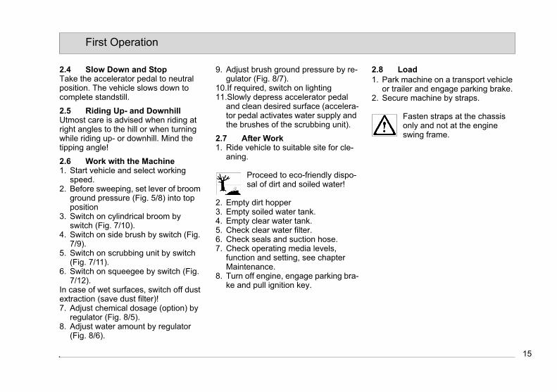
2.4 Slow Down and StopTake the accelerator pedal to neutral position. The vehicle slows down to complete standstill.
2.5 Riding Up- and DownhillUtmost care is advised when riding at right angles to the hill or when turning while riding up- or downhill. Mind the tipping angle!
2.6 Work with the Machine1. Start vehicle and select working
speed.2. Before sweeping, set lever of broom
ground pressure (Fig. 5/8) into top position
3. Switch on cylindrical broom by switch (Fig. 7/10).
4. Switch on side brush by switch (Fig. 7/9).
5. Switch on scrubbing unit by switch (Fig. 7/11).
6. Switch on squeegee by switch (Fig. 7/12).
In case of wet surfaces, switch off dust extraction (save dust filter)!7. Adjust chemical dosage (option) by
regulator (Fig. 8/5).8. Adjust water amount by regulator
(Fig. 8/6).
9. Adjust brush ground pressure by re-gulator (Fig. 8/7).
10.If required, switch on lighting11.Slowly depress accelerator pedal
and clean desired surface (accelera-tor pedal activates water supply and the brushes of the scrubbing unit).
2.7 After Work1. Ride vehicle to suitable site for cle-
aning.
Proceed to eco-friendly dispo-sal of dirt and soiled water!
2. Empty dirt hopper3. Empty soiled water tank.4. Empty clear water tank.5. Check clear water filter.6. Check seals and suction hose.7. Check operating media levels,
function and setting, see chapter Maintenance.
8. Turn off engine, engage parking bra-ke and pull ignition key.
2.8 Load1. Park machine on a transport vehicle
or trailer and engage parking brake.2. Secure machine by straps.
Fasten straps at the chassis only and not at the engine swing frame.
15
First Operation
2.4 Slow Down and StopTake the accelerator pedal to neutral position. The vehicle slows down to complete standstill.
2.5 Riding Up- and DownhillUtmost care is advised when riding at right angles to the hill or when turning while riding up- or downhill. Mind the tipping angle!
2.6 Work with the Machine1. Start vehicle and select working
speed.2. Before sweeping, set lever of broom
ground pressure (Fig. 5/8) into top position
3. Switch on cylindrical broom by switch (Fig. 7/10).
4. Switch on side brush by switch (Fig. 7/9).
5. Switch on scrubbing unit by switch (Fig. 7/11).
6. Switch on squeegee by switch (Fig. 7/12).
In case of wet surfaces, switch off dust extraction (save dust filter)!7. Adjust chemical dosage (option) by
regulator (Fig. 8/5).8. Adjust water amount by regulator
(Fig. 8/6).
9. Adjust brush ground pressure by re-gulator (Fig. 8/7).
10.If required, switch on lighting11.Slowly depress accelerator pedal
and clean desired surface (accelera-tor pedal activates water supply and the brushes of the scrubbing unit).
2.7 After Work1. Ride vehicle to suitable site for cle-
aning.
Proceed to eco-friendly dispo-sal of dirt and soiled water!
2. Empty dirt hopper3. Empty soiled water tank.4. Empty clear water tank.5. Check clear water filter.6. Check seals and suction hose.7. Check operating media levels,
function and setting, see chapter Maintenance.
8. Turn off engine, engage parking bra-ke and pull ignition key.
2.8 Load1. Park machine on a transport vehicle
or trailer and engage parking brake.2. Secure machine by straps.
Fasten straps at the chassis only and not at the engine swing frame.

16
First Operation
2.9 Tie-down pointsThe front sides of both wheel housings are equipped with an opening (Fig. 2/2) for tying down the front part of the ma-chine. Secure the rear part of the ma-chine with a hook or an eye (Fig. 2/3).
Fig.2
2.10 Towing
Do not tow the vehicle for a di-stance of 800 metres and more and do not exceed a towing velocity of 1.5 km/h. If these li-mit values are not adhered to, the hydraulic system may be damaged. If the above mentio-ned values are exceeded lift-up the rear wheel or place it on a roll board.
Actuate the bypass valve before towing.1. Open engine hood, siehe Abschnitt
5.5.1.2. The bypass valve is located at the
front wall of the hydraulic tank.3. Turn lever (Fig. 2/1) of the bypass
valve clockwise by 90°.4. The vehicle then can be pushed or
towed.
Generally tow the vehicle with the rear wheel lifted!
2.11 Support Points
Safely jack the vehicle. Do not rely on stands alone.
Place stands under the front border of the wheel housing at the chassis. Sup-port the rear vehicle part by placing jacks under the chassis next to the rear lights.
12 3
17
Operation
3 Operation
3.1 Method of Operation
3.1.1 General
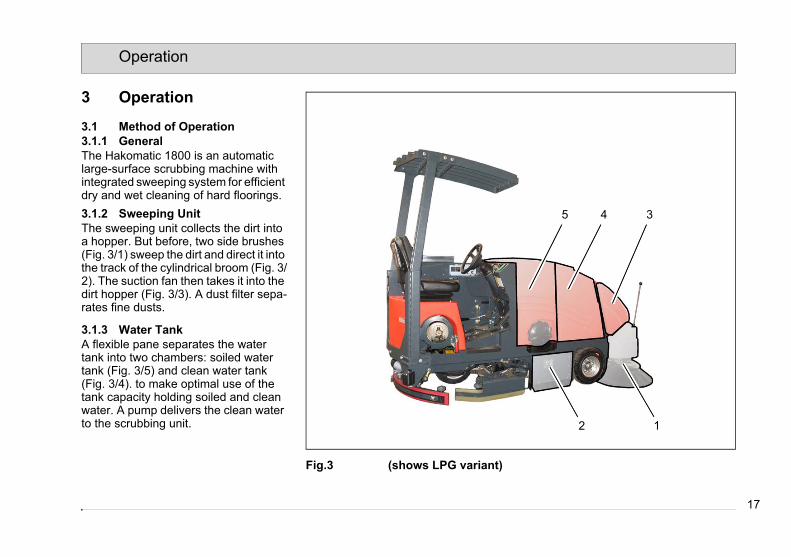
The Hakomatic 1800 is an automatic large-surface scrubbing machine with integrated sweeping system for efficient dry and wet cleaning of hard floorings.
3.1.2 Sweeping Unit
The sweeping unit collects the dirt into a hopper. But before, two side brushes (Fig. 3/1) sweep the dirt and direct it into the track of the cylindrical broom (Fig. 3/2). The suction fan then takes it into the dirt hopper (Fig. 3/3). A dust filter sepa-rates fine dusts.
3.1.3 Water Tank
A flexible pane separates the water tank into two chambers: soiled water tank (Fig. 3/5) and clean water tank (Fig. 3/4). to make optimal use of the tank capacity holding soiled and clean water. A pump delivers the clean water to the scrubbing unit.
Fig.3 (shows LPG variant)
2 1
345
17
Operation
3 Operation
3.1 Method of Operation
3.1.1 General
The Hakomatic 1800 is an automatic large-surface scrubbing machine with integrated sweeping system for efficient dry and wet cleaning of hard floorings.
3.1.2 Sweeping Unit
The sweeping unit collects the dirt into a hopper. But before, two side brushes (Fig. 3/1) sweep the dirt and direct it into the track of the cylindrical broom (Fig. 3/2). The suction fan then takes it into the dirt hopper (Fig. 3/3). A dust filter sepa-rates fine dusts.
3.1.3 Water Tank
A flexible pane separates the water tank into two chambers: soiled water tank (Fig. 3/5) and clean water tank (Fig. 3/4). to make optimal use of the tank capacity holding soiled and clean water. A pump delivers the clean water to the scrubbing unit.
Fig.3 (shows LPG variant)
2 1
345

18
Operation
3.1.4 Scrubbing Unit
The suspended scrubbing unit (Fig. 4/1) comprises three hydraulically driven scrubbing brushes, the lateral wipers and a water supply system.
3.1.5 Squeegee
The suspended squeegee (Fig. 4/2) comprises the squeegee lift-out system, suction turbine and sealing strips. The-se sealing strips wipe the soiled water off the floor by and a suction turbine takes it into the soiled water tank. In re-verse ride, the squeegee is automati-cally lifted out.
3.1.6 Travel Drive and Work Hy-
draulics
The combustion engine (Fig. 4/3) provi-des for direct drive of the drive pump and the hydraulic pumps for steering/sweeping unit and scrubbing unit. Tra-vel drive assembly and work hydraulics are protected by oil cooler and corre-sponding filters.
3.1.7 Options
Protective roof, rotating beacon and se-cond liquid propellant gas tank (Fig. 4/4)
Fig.4
1 2 3
4

19
Operation
3.2 Control and Display Elements
3.2.1 Overview
1 Main control panel2 Left-hand control panel3 Driver seat4 Accelerator pedal5 Brake6 Parking brake7 Wearing compensation for cylindri-
cal broom8 Broom ground pressure9 Valve for gas cylinder10 Clear water drain valve11 Clean water sieve12 Safety stand13 Wearing compensation for side
brushes14 Clear water stop valve
Fig.5
2 1
6
3
89
7
45
13
10 11
12
14
22
20
Operation
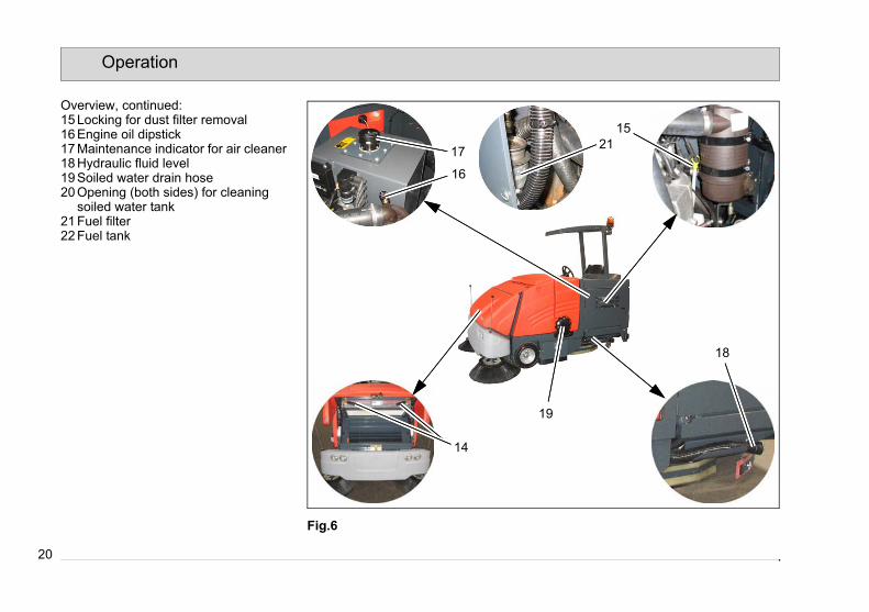
Overview, continued:15 Locking for dust filter removal16 Engine oil dipstick17 Maintenance indicator for air cleaner18 Hydraulic fluid level19 Soiled water drain hose20 Opening (both sides) for cleaning
soiled water tank21 Fuel filter22 Fuel tank
Fig.6
15
14
16
17
18
19
21
20
Operation
Overview, continued:15 Locking for dust filter removal16 Engine oil dipstick17 Maintenance indicator for air cleaner18 Hydraulic fluid level19 Soiled water drain hose20 Opening (both sides) for cleaning
soiled water tank21 Fuel filter22 Fuel tank
Fig.6
15
14
16
17
18
19
21

21
Operation
3.2.2 Main Control Panel
1 Spark sensor pilot lamp (optional)2 Brake pilot lamp3 Dust filter pilot lamp4 Multi-function display5 Clean water pilot lamp6 Soiled water pilot lamp7 Engine temperature pilot lamp8 Engine speed switch9 Side brush switch10 Sweeping mode switch11 Scrubbing unit switch12 Squeegee switch13 Ignition switch14 Light switch15 Signal horn switch16 Jolter switch17 Hopper flap switch18 Dirt hopper lever
Fig.7
1 2 3 5 6 74 8
9
1011
12
17
18
1314
15
16

22
Operation
Spark sensor pilot lamp (Option)
(Fig. 7/1)
lights if sensor detects objects such as glowing cigarette ends.
Brake pilot lamp (Fig. 7/2)
lights after actuation of brake or if par-king brake has been engaged.
Dust filter pilot lamp (Fig. 7/3)
The pilot lamp lights after dust filter has attained maximum degree of soiling. Switch on jolter by switch (Fig. 7/16).
Multi-function display (Fig. 7/4)
Multi-functional display holds indicators for fuel level, battery charge, oil pressu-re, coolant temperature and hourmeter.Fuel gauge indicates fuel filling level, but only for petrol and diesel versions, for liquid propellant gas versions this gauge is off. Battery display shows charge status or generator charge. Equally displays di-scharge by machine operation if gene-rator does not charge battery.
Oil pressure indication shows current engine oil pressure
Radiator temperature gauge shows en-gine coolant temperature. If tempera-tures of 110° C and more are attained, overheating is indicated.Hourmeter indicates the time with run-ning motor.
Clean water pilot lamp (Fig. 7/5)
lights if clean water tank is empty. For re-filling clean water tank, see chapter Maintenance.
Soiled water pilot lamp (Fig. 7/6)
lights if soiled water tank is filled. For emptying soiled water tank, see chapter Maintenance.
23
Operation
Engine pilot lamp (Fig. 7/7)
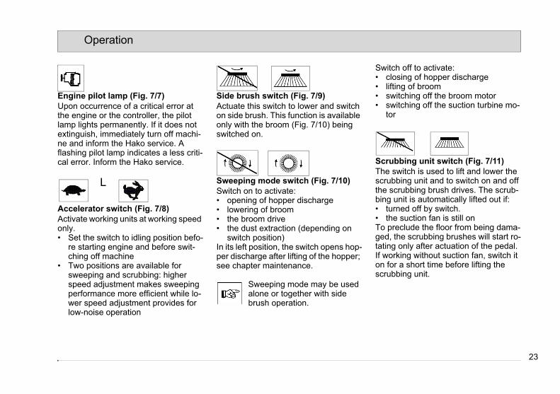
Upon occurrence of a critical error at the engine or the controller, the pilot lamp lights permanently. If it does not extinguish, immediately turn off machi-ne and inform the Hako service. A flashing pilot lamp indicates a less criti-cal error. Inform the Hako service.
Accelerator switch (Fig. 7/8)
Activate working units at working speed only.• Set the switch to idling position befo-
re starting engine and before swit-ching off machine
• Two positions are available for sweeping and scrubbing: higher speed adjustment makes sweeping performance more efficient while lo-wer speed adjustment provides for low-noise operation
Side brush switch (Fig. 7/9)
Actuate this switch to lower and switch on side brush. This function is available only with the broom (Fig. 7/10) being switched on.
Sweeping mode switch (Fig. 7/10)
Switch on to activate:• opening of hopper discharge• lowering of broom• the broom drive• the dust extraction (depending on
switch position)In its left position, the switch opens hop-per discharge after lifting of the hopper; see chapter maintenance.
Sweeping mode may be used alone or together with side brush operation.
Switch off to activate:• closing of hopper discharge• lifting of broom• switching off the broom motor• switching off the suction turbine mo-
tor
Scrubbing unit switch (Fig. 7/11)
The switch is used to lift and lower the scrubbing unit and to switch on and off the scrubbing brush drives. The scrub-bing unit is automatically lifted out if:• turned off by switch.• the suction fan is still onTo preclude the floor from being dama-ged, the scrubbing brushes will start ro-tating only after actuation of the pedal.If working without suction fan, switch it on for a short time before lifting the scrubbing unit.
L
23
Operation
Engine pilot lamp (Fig. 7/7)
Upon occurrence of a critical error at the engine or the controller, the pilot lamp lights permanently. If it does not extinguish, immediately turn off machi-ne and inform the Hako service. A flashing pilot lamp indicates a less criti-cal error. Inform the Hako service.
Accelerator switch (Fig. 7/8)
Activate working units at working speed only.• Set the switch to idling position befo-
re starting engine and before swit-ching off machine
• Two positions are available for sweeping and scrubbing: higher speed adjustment makes sweeping performance more efficient while lo-wer speed adjustment provides for low-noise operation
Side brush switch (Fig. 7/9)
Actuate this switch to lower and switch on side brush. This function is available only with the broom (Fig. 7/10) being switched on.
Sweeping mode switch (Fig. 7/10)
Switch on to activate:• opening of hopper discharge• lowering of broom• the broom drive• the dust extraction (depending on
switch position)In its left position, the switch opens hop-per discharge after lifting of the hopper; see chapter maintenance.
Sweeping mode may be used alone or together with side brush operation.
Switch off to activate:• closing of hopper discharge• lifting of broom• switching off the broom motor• switching off the suction turbine mo-
tor
Scrubbing unit switch (Fig. 7/11)
The switch is used to lift and lower the scrubbing unit and to switch on and off the scrubbing brush drives. The scrub-bing unit is automatically lifted out if:• turned off by switch.• the suction fan is still onTo preclude the floor from being dama-ged, the scrubbing brushes will start ro-tating only after actuation of the pedal.If working without suction fan, switch it on for a short time before lifting the scrubbing unit.
L

24
Operation
Squeegee switch (Fig. 7/12)This switch allows lifting and lowering of the squeegee and switching on and off the suction fan.
Ignition switch (Fig. 7/13)Close and lock the engine swing frame and open the gas valve before starting.
Switch on the electrical system and start engine by means of the ignition key.Turn key fully right to start engine and release key after engine cranks.To stop engine turn ignition key to the left to OFF position.
Light switch (Fig. 7/14)to switch the head- and rear lights on and off.
Signal horn switch(Fig. 7/15)to switch the signal horn on.
Jolter switch (Fig. 7/16)This tipswitch allows switching on the jolter motor in the sweeping unit for cle-aning of the dust filter.
Hopper flap switch (Fig. 7/17)to open the dirt hopper flap. If dirt hop-per flap is opened with the hopper being lifted, manual closing is not available. Hopper flap will be automatically locked upon lowering.
Dirt hopper lever (Fig. 7/18)This lever is used to lift and lower the dirt hopper.• Push lever: dirt hopper lowers• Pull lever: dirt hopper lifts
Fit safety stand before working under the dirt hopper. Pinching hazard!

25
Operation
3.2.3 Left-hand Control Panel1 not assigned2 not assigned3 not assigned4 Switch for dust extraction in
sweeping mode5 Chemical agent control (optional)6 Water dosage control7 Control of scrubbing brush ground
pressure
Fig.8
Switch for scrubbing unit suction fan (Fig. 8/4)to switch suction fan on and off. Switch off dust extraction when working on wet surfaces (Protect dust filter from dust deposits!).
Chemical agent control (optional) (Fig. 8/5)This controller is used to adjust one of four stages for cleaning lye supply to the scrubbing unit.Stage 1 = OffStage 2 = minimum supplyStage 3 = medium supplyStage 4 = maximum supplySupply is switched off when scrubbing unit lifts. If it is lowered again, supply of the adjusted amount is re-activated.
Clean water control (Fig. 8/6)This controller is used to adjust one of four stages for clean water supply to the scrubbing unit.Stage 1 = OffStage 2 = minimum supplyStage 3 = medium supplyStage 4 = maximum supplySupply is switched off when scrubbing unit lifts. If it is lowered again, supply of the adjusted amount is re-activated.
Control of scrubbing brush ground pressure (Fig. 8/7)Use this regulator to set scrubbing brush ground pressure to one of three stages. Excessive ground pressure causes higher brush wearing and may damage the floor surface!
1 2 3 4
5 76
26
Operation
3.2.4 Controls of the Machine
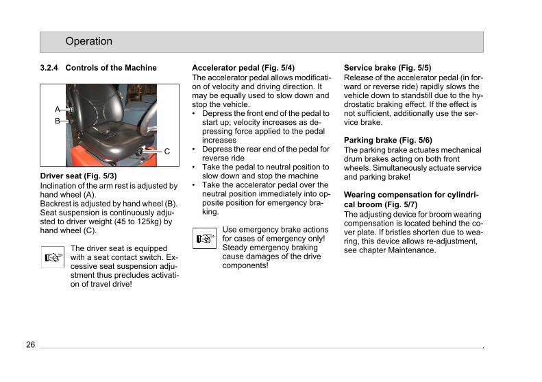
Driver seat (Fig. 5/3)Inclination of the arm rest is adjusted by hand wheel (A).Backrest is adjusted by hand wheel (B). Seat suspension is continuously adju-sted to driver weight (45 to 125kg) by hand wheel (C).
The driver seat is equipped with a seat contact switch. Ex-cessive seat suspension adju-stment thus precludes activati-on of travel drive!
Accelerator pedal (Fig. 5/4) The accelerator pedal allows modificati-on of velocity and driving direction. It may be equally used to slow down and stop the vehicle.• Depress the front end of the pedal to
start up; velocity increases as de-pressing force applied to the pedal increases
• Depress the rear end of the pedal for reverse ride
• Take the pedal to neutral position to slow down and stop the machine
• Take the accelerator pedal over the neutral position immediately into op-posite position for emergency bra-king.
Use emergency brake actions for cases of emergency only! Steady emergency braking cause damages of the drive components!
Service brake (Fig. 5/5) Release of the accelerator pedal (in for-ward or reverse ride) rapidly slows the vehicle down to standstill due to the hy-drostatic braking effect. If the effect is not sufficient, additionally use the ser-vice brake.
Parking brake (Fig. 5/6) The parking brake actuates mechanical drum brakes acting on both front wheels. Simultaneously actuate service and parking brake!
Wearing compensation for cylindri-cal broom (Fig. 5/7)The adjusting device for broom wearing compensation is located behind the co-ver plate. If bristles shorten due to wea-ring, this device allows re-adjustment, see chapter Maintenance.
A
B
C
26
Operation
3.2.4 Controls of the Machine
Driver seat (Fig. 5/3)Inclination of the arm rest is adjusted by hand wheel (A).Backrest is adjusted by hand wheel (B). Seat suspension is continuously adju-sted to driver weight (45 to 125kg) by hand wheel (C).
The driver seat is equipped with a seat contact switch. Ex-cessive seat suspension adju-stment thus precludes activati-on of travel drive!
Accelerator pedal (Fig. 5/4) The accelerator pedal allows modificati-on of velocity and driving direction. It may be equally used to slow down and stop the vehicle.• Depress the front end of the pedal to
start up; velocity increases as de-pressing force applied to the pedal increases
• Depress the rear end of the pedal for reverse ride
• Take the pedal to neutral position to slow down and stop the machine
• Take the accelerator pedal over the neutral position immediately into op-posite position for emergency bra-king.
Use emergency brake actions for cases of emergency only! Steady emergency braking cause damages of the drive components!
Service brake (Fig. 5/5) Release of the accelerator pedal (in for-ward or reverse ride) rapidly slows the vehicle down to standstill due to the hy-drostatic braking effect. If the effect is not sufficient, additionally use the ser-vice brake.
Parking brake (Fig. 5/6) The parking brake actuates mechanical drum brakes acting on both front wheels. Simultaneously actuate service and parking brake!
Wearing compensation for cylindri-cal broom (Fig. 5/7)The adjusting device for broom wearing compensation is located behind the co-ver plate. If bristles shorten due to wea-ring, this device allows re-adjustment, see chapter Maintenance.
A
B
C
27
Operation
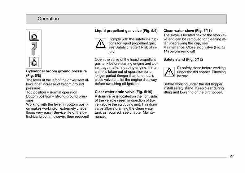
Cylindrical broom ground pressure (Fig. 5/8)The lever at the left of the driver seat al-lows brief increase of broom ground pressure.Top position = normal operationBottom position = strong ground pres-sureWorking with the lever in bottom positi-on makes working on extremely uneven floors very easy. Service life of the cy-lindrical broom, however, then reduced!
Liquid propellant gas valve (Fig. 5/9)
Comply with the safety instruc-tions for liquid propellant gas, see Safety chapter! Risk of in-jury!
Open the valve of the liquid propellant gas tank before starting engine and clo-se it again after stopping engine. If ma-chine is taken out of operation for a longer period (longer than one hour), close valve and let the engine die away before switching off ignition!
Clear water drain valve (Fig. 5/10)A drain valve is located on the right side of the vehicle (seen in direction of tra-vel) above the scrubbing unit. This drain valve allows draining the clean water tank as required, see chapter Mainte-nance.
Clean water sieve (Fig. 5/11)The sieve is located next to the stop val-ve and can be removed for cleaning af-ter unscrewing the cap, see Maintenance. Close stop valve (Fig. 5/14) before removal!
Safety stand (Fig. 5/12)
Fit safety stand before working under the dirt hopper. Pinching hazard!
Before working under the dirt hopper, install safety stand. Keep clear during lifting and lowering of the dirt hopper.
27
Operation
Cylindrical broom ground pressure (Fig. 5/8)The lever at the left of the driver seat al-lows brief increase of broom ground pressure.Top position = normal operationBottom position = strong ground pres-sureWorking with the lever in bottom positi-on makes working on extremely uneven floors very easy. Service life of the cy-lindrical broom, however, then reduced!
Liquid propellant gas valve (Fig. 5/9)
Comply with the safety instruc-tions for liquid propellant gas, see Safety chapter! Risk of in-jury!
Open the valve of the liquid propellant gas tank before starting engine and clo-se it again after stopping engine. If ma-chine is taken out of operation for a longer period (longer than one hour), close valve and let the engine die away before switching off ignition!
Clear water drain valve (Fig. 5/10)A drain valve is located on the right side of the vehicle (seen in direction of tra-vel) above the scrubbing unit. This drain valve allows draining the clean water tank as required, see chapter Mainte-nance.
Clean water sieve (Fig. 5/11)The sieve is located next to the stop val-ve and can be removed for cleaning af-ter unscrewing the cap, see Maintenance. Close stop valve (Fig. 5/14) before removal!
Safety stand (Fig. 5/12)
Fit safety stand before working under the dirt hopper. Pinching hazard!
Before working under the dirt hopper, install safety stand. Keep clear during lifting and lowering of the dirt hopper.
28
Operation
Wearing compensation for side brushes (Fig. 5/13)An adjustment device for wearing com-pensation of side brushes is located un-der the front hood at the right vehicle side (seen in direction of travel). If brist-les shorten due to wearing, this device allows re-adjustment, see chapter Maintenance.
Clear water stop valve (Fig. 5/14)At the right vehicle side (seen in direc-tion of travel), a clear water stop valve is over the scrubbing unit. For cleaning the clear water filter close the valve, see chapter maintenance
Dust filter lock (Fig. 5/15)The dust filter is located under the front hood. Before dismounting the dust filter, open both levers of the lock, see chap-ter Maintenance.
Dipstick for engine oil level (Fig. 5/16)The dipstick is situated on the right en-gine side. Check the engine oil level at daily intervals (before work) and re-fill oil if required, see chapter Maintenance
Maintenance indication for air clea-ner (Fig. 5/17)The air cleaner is situated at the right engine side. Check the maintenance in-dication at weekly intervals and change filter element if required, see chapter Maintenance
Dipstick for hydraulic fluid level (Fig. 5/18)The dipstick for hydraulic fluid level is located in the cap of the hydraulic fluid tank. Check hydraulic fluid level at weekly intervals and refill hydraulic fluid if required, see chapter Maintenance.
Soiled water drain hose (Fig. 5/19)A hose is located above the scrubbing unit on the left vehicle side (seen in di-rection of travel) for draining soiled wa-ter. If soiled water indication flashes, empty soiled water tank, see chapter Maintenance.
Opening (both sides) for cleaning soiled water tank (Fig. 5/20)The lid provided on both sides of the soiled water tank allows easy cleaning. Clean soiled water tank, see chapter Maintenance.
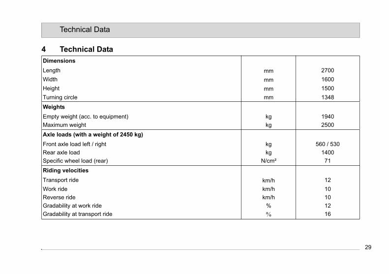
29
Technical Data
4 Technical Data
Dimensions
Length mm 2700
Width mm 1600
Height mm 1500
Turning circle mm 1348
Weights
Empty weight (acc. to equipment) kg 1940
Maximum weight kg 2500
Axle loads (with a weight of 2450 kg)
Front axle load left / right kg 560 / 530
Rear axle load kg 1400
Specific wheel load (rear) N/cm² 71
Riding velocities
Transport ride km/h 12
Work ride km/h 10
Reverse ride km/h 10
Gradability at work ride % 12
Gradability at transport ride % 16
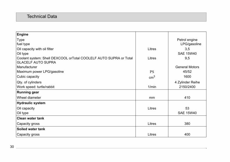
30
Technical Data
Engine
Typefuel type
Petrol engineLPG/gasoline
Oil capacity with oil filter Litres 3,5Oil type SAE 15W40Coolant system: Shell DEXCOOL orTotal COOLELF AUTO SUPRA or Total GLACELF AUTO SUPRA
Litres 9,5
Manufacturer General MotorsMaximum power LPG/gasoline PS 45/52
Cubic capacity cm3 1600
Qty. of cylinders 4 Zylinder ReiheWork speed: turtle/rabbit 1/min 2150/2400
Running gear
Wheel diameter mm 410
Hydraulic system
Oil capacity Litres 53Oil type SAE 15W40
Clean water tank
Capacity gross Litres 380
Soiled water tank
Capacity gross Litres 400
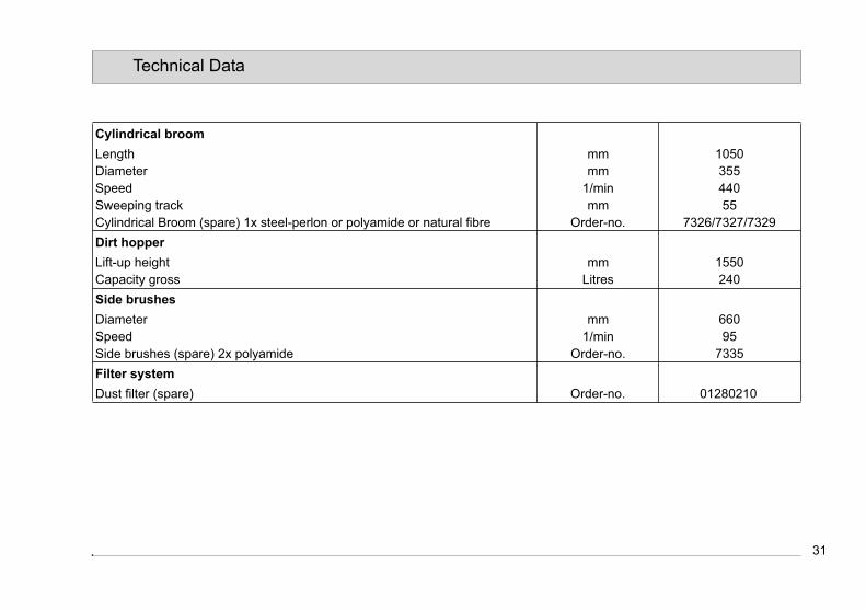
31
Technical Data
Cylindrical broom
Length mm 1050Diameter mm 355Speed 1/min 440Sweeping track mm 55Cylindrical Broom (spare) 1x steel-perlon or polyamide or natural fibre Order-no. 7326/7327/7329
Dirt hopper
Lift-up height mm 1550Capacity gross Litres 240
Side brushes
Diameter mm 660Speed 1/min 95Side brushes (spare) 2x polyamide Order-no. 7335
Filter system
Dust filter (spare) Order-no. 01280210

32
Technical Data
Scrubbing unit
Qty. of brushes Pcs. 3
Brush diameter mm 410
Brush speed 1/min 200
Brush ground press., stage 1/2/3/4 kg Off/easy/middle/strong
Brush (spare) 3x polyamide or K 180 or SIC PA grain 120 Order-no. 7337/7339/7340
Brush (spare) 3x SIC PA grain 80 or SIC PA grain 46 or wire Order-no. 7341/7343/7346
Sealing (spare) 2x rear/front Order-no. 01285130/01285140
Squeegee
Working width mm 1350
Sealing (spare) 1x outside/inside Order-no. 01285130/01285140
Suction fan scrubbing unit
Max. low pressure mbar 80
Speed 1/min 9300
Suction fan sweeping unit
Max. low pressure mbar 13
Speed 1/min 3900
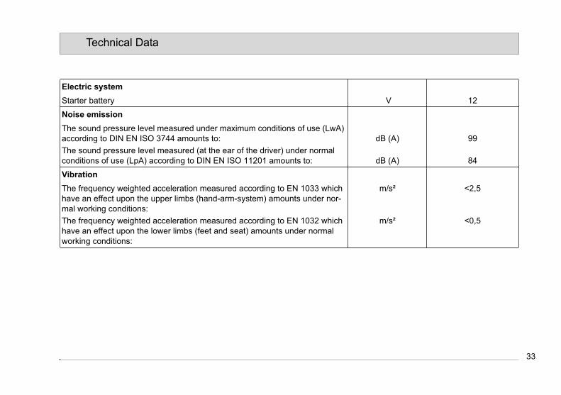
33
Technical Data
Electric system
Starter battery V 12
Noise emission
The sound pressure level measured under maximum conditions of use (LwA) according to DIN EN ISO 3744 amounts to: dB (A) 99
The sound pressure level measured (at the ear of the driver) under normal conditions of use (LpA) according to DIN EN ISO 11201 amounts to: dB (A) 84
Vibration
The frequency weighted acceleration measured according to EN 1033 which have an effect upon the upper limbs (hand-arm-system) amounts under nor-mal working conditions:
m/s² <2,5
The frequency weighted acceleration measured according to EN 1032 which have an effect upon the lower limbs (feet and seat) amounts under normal working conditions:
m/s² <0,5

34
Maintenance and Care
5 Maintenance and Care
5.1 GeneralBefore proceeding to mainte-nance and care work you are advised to read and comply with the Safety Information chapter!
Compliance with the recommended maintenance works will give you the certitude of always having a reliable machine at disposition.Daily or weekly maintenance and repair works may be executed by the driver/operator having been trained accordin-gly. Further Hako system maintenance works have to be executed by qualified personnel only. Please contact your lo-cal Hako Service Centre or Hako con-tract dealer. We cannot be held liable for damages resulting from non-com-pliance with these instructions.Please indicate the machine's serial number with any enquiry or spare part order, see paragraph 1.7 - Nameplate.
5.2 Hako System MaintenanceThe Hako System Maintenance: • guarantees reliable operability of the
Hako machines (preventive mainte-nance)
• minimizes operating costs, repair costs and maintenance costs
• ensures long service life and opera-bility of the machine
The Hako System Maintenance is structured in separate modules and de-termines specific technical works to be executed as well as the intervals for such maintenance works. For any spe-cific maintenance type, the replacement parts are determined and listed in spare part kits.Hako System Maintenance K:
To be performed by the customer in ac-cordance to the maintenance and care instructions contained in the operating instructions (daily or weekly). The driver/operator will be instructed upon delivery of the machine.Hako-System Maintenance I :
(uniquely after 50 hours of operation)Applies for machines which are opera-ted by internal combustion engines, first oil change, filter etc. To be performed by qualified personnel
of authorised Hako Service Centre.Hako-System Maintenance II:
(250 hours of operation)To be performed by qualified personnel of authorised Hako Service Centre in accordance with the machine-specific system maintenance including spare part kit.Hako-System Maintenance III:
(500 hours of operation)To be performed by qualified personnel of authorised Hako Service Centre in accordance with the machine-specific system maintenance including spare part kit.Hako-System Maintenance S:
(1000 hours of operation safety check)To be performed by qualified personnel of authorised Hako Service Centre in accordance with the machine-specific system maintenance including spare part kit. Execution of all safety-relevant inspections according to UVV-BGV-TÜV-VDE as prescribed by law.
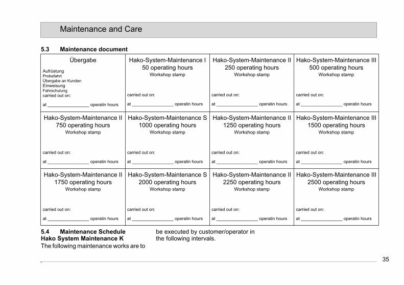
35
Maintenance and Care
5.3 Maintenance document
5.4 Maintenance ScheduleHako System Maintenance K
The following maintenance works are to
be executed by customer/operator in the following intervals.
Übergabe
AufrüstungProbefahrtÜbergabe an KundenEinweisungFahrschulungcarried out on:
at _________________ operatin hours
Hako-System-Maintenance I 50 operating hours
Workshop stamp
carried out on:
at _________________ operatin hours
Hako-System-Maintenance II 250 operating hours
Workshop stamp
carried out on:
at _________________ operatin hours
Hako-System-Maintenance III 500 operating hours
Workshop stamp
carried out on:
at _________________ operatin hours
Hako-System-Maintenance II 750 operating hours
Workshop stamp
carried out on:
at _________________ operatin hours
Hako-System-Maintenance S 1000 operating hours
Workshop stamp
carried out on:
at _________________ operatin hours
Hako-System-Maintenance II 1250 operating hours
Workshop stamp
carried out on:
at _________________ operatin hours
Hako-System-Maintenance III 1500 operating hours
Workshop stamp
carried out on:
at _________________ operatin hours
Hako-System-Maintenance II 1750 operating hours
Workshop stamp
carried out on:
at _________________ operatin hours
Hako-System-Maintenance S 2000 operating hours
Workshop stamp
carried out on:
at _________________ operatin hours
Hako-System-Maintenance II 2250 operating hours
Workshop stamp
carried out on:
at _________________ operatin hours
Hako-System-Maintenance III 2500 operating hours
Workshop stamp
carried out on:
at _________________ operatin hours

36
Maintenance and Care
To be performedIntervals
daily weekly
Check engine oil level and refill if required o
Check hydraulic fluid level and refill if required o
Check engine coolant level and refill if required o
Engine suction filter: check degree of soiling on maintenance indicator and clean filter element and dust discharge valve if required
o
LPG system: change liquid propellant gas tank if required o
Engine and hydraulic system: visual check for leakage o
Check accelerator pedal function o
Squeegee: check function, adjust ground pressure and contact if required o
Suction hose: check function and remove jamming if required o
Empty and clean soiled water tank o
Clean soiled water drain hose o
Remove foreign particles from cylindrical broom and duct o
Clean clear water filter o
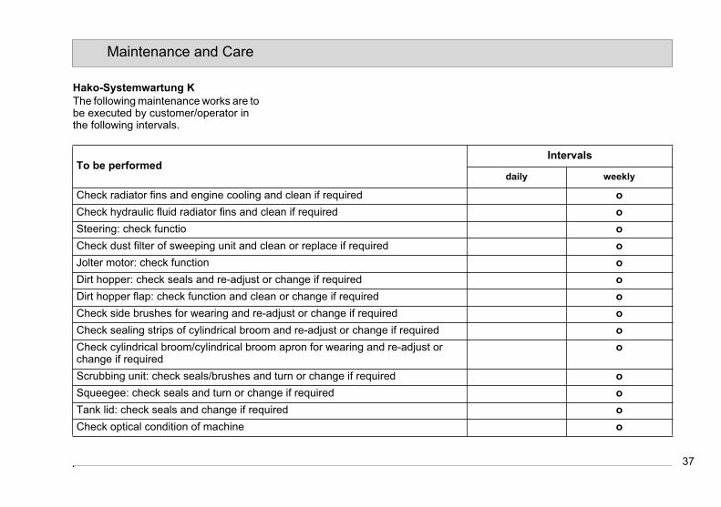
37
Maintenance and Care
Hako-Systemwartung K
The following maintenance works are to be executed by customer/operator in the following intervals.
To be performedIntervals
daily weekly
Check radiator fins and engine cooling and clean if required o
Check hydraulic fluid radiator fins and clean if required o
Steering: check functio o
Check dust filter of sweeping unit and clean or replace if required o
Jolter motor: check function o
Dirt hopper: check seals and re-adjust or change if required o
Dirt hopper flap: check function and clean or change if required o
Check side brushes for wearing and re-adjust or change if required o
Check sealing strips of cylindrical broom and re-adjust or change if required o
Check cylindrical broom/cylindrical broom apron for wearing and re-adjust or change if required
o
Scrubbing unit: check seals/brushes and turn or change if required o
Squeegee: check seals and turn or change if required o
Tank lid: check seals and change if required o
Check optical condition of machine o

38
Maintenance and Care
Hako System Maintenance I
The following maintenance works are to be executed by an authorised Hako Service workshop.
To be performedIntervals
50 hours of operation (uniquely)
Change engine oil and engine oil filter o
Change fuel filter (of fuel variant) o
Change hydraulic fluid filter o
Hydraulic system: check function o
Engine and hydraulic system: visual check for leakage o
Check engine idling and service speeds o
Electrical system: check starter battery, lighting and pilot lamps o
Check liquid propellant gas system o
Service and parking brake: check function o
Steering: check function o
Check operating mode: accelerator pedal, forward and reverse ride and neutral posi-tion
o
Check optical condition of machine o
Trial ride o

39
Maintenance and Care
Hako System Maintenanc II
The following maintenance works are to be executed by an authorised Hako Service workshop at least once yearly.
To be performedIntervals
every 250 hours of operation
Change engine oil and engine oil filter o
Engine suction filter: check degree of soiling according to maintenance indicator, clean filter element and dust discharge valve if required
o
Engine and hydraulic system: visual check for leakage o
Check engine idling and service speeds o
Check and clean service brake o
Check and clean parking brake o
Check liquid propellant gas system (check CO-value every six months at least) o
Wheels: check torque o
Hydraulic system: check function of motors, valves and pumps o
Electrical system: check starter battery, lighting and pilot lamps o
Check optical condition of machine o
Trial ride o

40
Maintenance and Care
Hako System Maintenance III
The following maintenance works are to be executed by an authorised Hako Service workshop at least once yearly.
To be performedIntervals
every 500 hours of operation
Perform maintenance works according to Hako System Maintenance II o
Engine suction filter: change filter element o
Change fuel filter (of fuel variant) o
Check antistatic chain and replace if required o
Change hydraulic fluid filter o
41
Maintenance and Care
Hako System Maintenance S (Safety
check)
The following maintenance works are to be executed by an authorised Hako Service workshop at least once yearly.
To be performedIntervals
every 1000 hours of operation
Perform maintenance works according to Hako System Maintenance III o
Engine suction filter: change filter and safety element o
Change engine coolant o
Change hydraulic fluid o
Brake system: change brake shoes o
Change side brush hoist rope and brake cable o

42
Maintenance and Care
5.5 Engine
The engine is located in the rear of the vehicle and is easily accessible for maintenance and care due to a swing frame.
1 Lid2 Dipstick3 Oil filter4 Oil sump5 Engine frame6 Lock7 Left and right access doors8 Cooling system9 Air filter10 Safety pin
Fig.9
1
2
3
74
5 6
8 9
107

43
Maintenance and Care
5.5.1 Open Engine Frame
Do not open engine frame be-fore engine has cooled down. Risk of injury!
1. Park vehicle with warmed engine on level ground. Turn engine off and let it cool down. Engage parking brake.
2. Unlock and swing up engine cover hood.
3. Swing open left and right engine ac-cess doors (Fig. 9/7).
4. Open lock (Fig. 9/6) and swing aside engine frame (Fig. 9/5).
5. Secure engine frame with safety pin (Fig. 9/10).
5.5.2 Refill Engine OilCheck engine oil level at daily intervals by means of dipstick (Fig. 9/2).Refill oil if required or when engine oil pilot lamp lights.
Use prescribed engine oil type, see Technical Data.
1. Park vehicle on level ground and open engine frame, siehe Abschnitt
5.5.12. Pull dipstick and wipe with clean
cloth.3. Check oil level on the markings at
the lower end of the dipstick.4. Do not fill oil all at once. Wait some
minutes until oil has flown into the oil sump before checking filling level again.
5. Re-install lid and dipstick.6. Lock engine frame. Close access
doors and cover hood.7. Engine pilot lamp has to extinguish
some seconds after engine has cranked.
5.5.3 Change Engine Oil and Oil Fil-ter
Change engine oil after first 50 hours of operation and after every 250 hours of operation but in yearly intervals at the latest.
Utmost care is recommended at hot engine parts and boiling engine oil! Risk of burning!
1. Stop vehicle on level ground and open engine frame, siehe Abschnitt 5.5.1.
2. Place appropriate receptacle under drain plug of the oil sump.Oil filling with oil filter: 3.5 litresOil filling without oil filter: 3.2 litres
3. Remove drain plug from oil sump (Fig. 9/4) and collect engine oil in re-ceptacle.
4. Remove oil filter (Fig. 9/3) and insert new oil filter with new sealing ring (Fasten oil filter hand-tight).
Provide for eco-friendly dispo-sal of used oil and used oil fil-ters!
5. Insert drain plug with new sealing ring.
6. Re-fill engine oil, siehe Abschnitt 5.5.2.

44
5.5.4 Change fuel filter The fuel filter is located at the left engi-ne frame side. Change filter after first 50 hours of operation, then after every 500 hours of operation.1. Open engine side flap.2. Loosen fixing screws (Fig. 9/4).3. Pull out filter holder (Fig. 9/3).4. Loosen by pulling the quick release
(Fig. 9/1) the fuel filter (Fig. 9/2) and change.
Fig.9
1
2
3
4
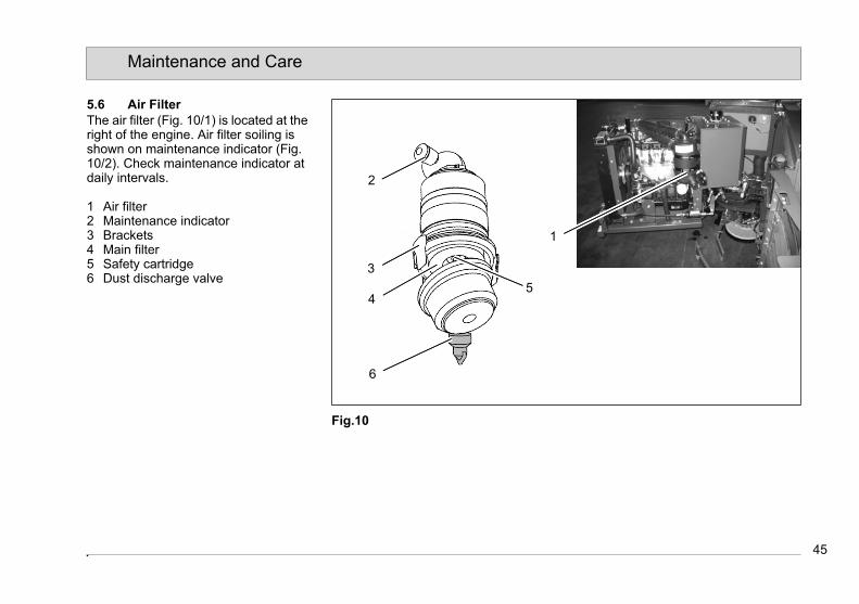
45
Maintenance and Care
5.6 Air Filter
The air filter (Fig. 10/1) is located at the right of the engine. Air filter soiling is shown on maintenance indicator (Fig.10/2). Check maintenance indicator at daily intervals.
1 Air filter2 Maintenance indicator3 Brackets4 Main filter5 Safety cartridge6 Dust discharge valve
Fig.10
1
2
3
4
6
5

46
Maintenance and Care
5.6.1 Remove Main Filter1. Open engine frame, siehe Abschnitt
5.5.1.2. Loosen brackets (Fig. 10/1) located
at the air filter (Fig. 10/3) and remove bottom housing part.
3. Remove main filter (Fig. 10/4) from housing.
5.6.2 Clean Main Filter1. Use damp cloth to clean bottom hou-
sing part inside.2. Blow out the main filter with com-
pressed air of a maximum pressure of 3bar from inside to outside.
3. Use lamp to check main filter for per-foration.
4. Check main filter sealing for dama-ges.
5.6.3 Install Main Filter1. Carefully insert the main filter by the
open side into the top housing part.2. Re-install bottom housing part while
having in mind the correct seating of the dust discharge valve (Fig. 10/6)achten.
3. Re-tighten brackets.
5.6.4 Change Main FilterChange main filter (Fig. 10/4) if dama-ged or, at the latest, after every 500 hours of operation.1. Remove main filter, siehe Abschnitt
5.6.1.2. Insert new main filter.3. Install main filter, siehe Abschnitt
5.6.3
5.6.5 Change Safety Cartridge
The safety cartridge (Fig. 10/5) must not be cleaned nor re-used after removal!
Change safety cartridge after every 1000 hours of operation at the latest.1. Remove main filter, siehe Abschnitt
5.6.1.2. Insert new safety cartridge.3. Install main filter, siehe Abschnitt
5.6.3
5.6.6 Clean Dust Discharge ValvePress together dust discharge valve (Fig. 10/6) to remove dust deposits.

47
Maintenance and Care
5.7 Cooling System
The coolant temperature is reduced in the radiator (Fig. 11/3) by a fan (Fig. 11/2) . Exceeding coolant temperature will be shown on main control panel.
Rotating parts in the near of the fan. Risk of injury!
1 Lid2 Fan3 Radiator4 Drain plug
Fig.11
2
3
4
1
47
Maintenance and Care
5.7 Cooling System
The coolant temperature is reduced in the radiator (Fig. 11/3) by a fan (Fig. 11/2) . Exceeding coolant temperature will be shown on main control panel.
Rotating parts in the near of the fan. Risk of injury!
1 Lid2 Fan3 Radiator4 Drain plug
Fig.11
2
3
4
1

48
Maintenance and Care
5.7.1 Clean RadiatorCheck radiator (Fig. 11/3) at daily inter-vals and clean if required. Dirt deposits on the fins reduce cooling performance.
The radiator fins are very thin and may be easily damaged!
1. Open engine frame, siehe Abschnitt 5.5.1.
2. Carefully blow out the radiator fins with compressed air from the engine side to the outside.
5.7.2 Re-fill Coolant
Do not open radiator before engine has cooled down since cooling system is under high pressure. Risk of injury! Wear protective gloves!
Insufficient coolant amount reduces cooling performance. Check coolant le-vel at weekly intervals and re-fill if requi-red.
Use prescribed coolant types only, see Technical Data! Do not mix different coolant types!
1. Open engine frame, siehe Abschnitt 5.5.1.
2. Carefully open lid (Fig. 11/1) after engine has cooled down.
3. Check coolant level. Coolant level should range between 20 and 30mm below the contact surface of the lid. Re-fill if required.
4. Re-install lid.5. Let engine run for some minutes.6. Turn engine off and let it cool down.7. Check coolant level again and re-fill
if required.
5.7.3 Change CoolantChange coolant after every 1000 hours of operation at the latest.1. Open engine frame, siehe Abschnitt
5.5.1.2. Place appropriate receptacle under
radiator drain plug (Fig. 11/4).3. Open drain plug and completely
drain coolant. Coolant = 9.5 litres
Collect used coolant and provi-de for eco-friendly disposal!
4. Re-plug drain plug.
5. Fill new coolant, see Technical Data6. Close lid.7. Let engine run for some minutes.8. Turn engine off and let it cool down.9. Check coolant level again and re-fill
if required.

49
Maintenance and Care
5.8 Liquid Propellant Gas System
Qualified persons only are au-thorised to work at the liquid propellant gas system! Only use parts as released by the manufacturer for installation or replacement of parts of the li-quid propellant gas system! Smoking and handling open flames is prohibited in the near of liquid propellant gas sy-stems! Work in sufficiently ven-tilated rooms only!
Standard
1 Standard liquid propellant gas tank2 Quick release3 Stop valve4 Lock
Second liquid propellant gas tank
option
5 Stop valve6 Quick release7 Second liquid propellant gas tank8 Fixing9 Change cock
Fig.12
1 2 3 4 5 6 7 8 9
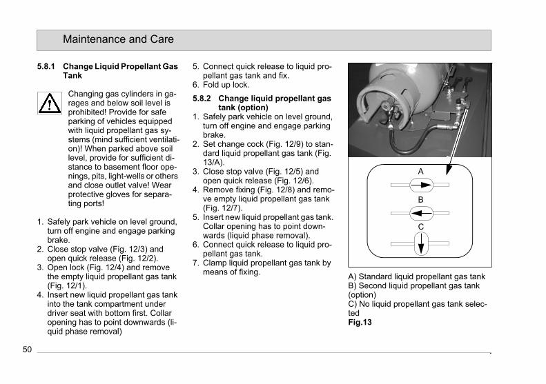
50
Maintenance and Care
5.8.1 Change Liquid Propellant Gas Tank
Changing gas cylinders in ga-rages and below soil level is prohibited! Provide for safe parking of vehicles equipped with liquid propellant gas sy-stems (mind sufficient ventilati-on)! When parked above soil level, provide for sufficient di-stance to basement floor ope-nings, pits, light-wells or others and close outlet valve! Wear protective gloves for separa-ting ports!
1. Safely park vehicle on level ground, turn off engine and engage parking brake.
2. Close stop valve (Fig. 12/3) and open quick release (Fig. 12/2).
3. Open lock (Fig. 12/4) and remove the empty liquid propellant gas tank (Fig. 12/1).
4. Insert new liquid propellant gas tank into the tank compartment under driver seat with bottom first. Collar opening has to point downwards (li-quid phase removal)
5. Connect quick release to liquid pro-pellant gas tank and fix.
6. Fold up lock.
5.8.2 Change liquid propellant gas tank (option)
1. Safely park vehicle on level ground, turn off engine and engage parking brake.
2. Set change cock (Fig. 12/9) to stan-dard liquid propellant gas tank (Fig. 13/A).
3. Close stop valve (Fig. 12/5) and open quick release (Fig. 12/6).
4. Remove fixing (Fig. 12/8) and remo-ve empty liquid propellant gas tank (Fig. 12/7).
5. Insert new liquid propellant gas tank. Collar opening has to point down-wards (liquid phase removal).
6. Connect quick release to liquid pro-pellant gas tank.
7. Clamp liquid propellant gas tank by means of fixing.
A) Standard liquid propellant gas tankB) Second liquid propellant gas tank (option)C) No liquid propellant gas tank selec-tedFig.13
B
A
C
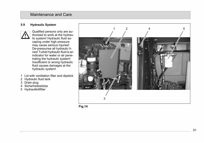
51
Maintenance and Care
5.9 Hydraulic System
Qualified persons only are au-thorised to work at the hydrau-lic system! Hydraulic fluid es-caping under high pressure may cause serious injuries!De-pressurise all hydraulic li-nes! Turbid hydraulic fluid is an indicator for water or air pene-trating the hydraulic system! Insufficient or wrong hydraulic fluid causes damages at the hydraulic system!
1 Lid with ventilation filter and dipstick2 Hydraulic fluid tank3 Drain plug4 Sicherheitsstütze5 Hydraulikölfilter
Fig.14
21
3
54
52
Maintenance and Care
5.9.1 Re-fill Hydraulic Fluid
Use prescribed hydraulic fluid type, see Technical Data!
1. Open engine frame, siehe Abschnitt 5.5.1
2. Remove lid (Fig. 14/1) and wipe dipstick with clean cloth.
3. Check fluid level by the marking at the bottom dipstick end.
4. Do not fill excessive amounts of fluid. Wait some minutes till the fluid has flown into the hydraulic fluid tank be-fore proceeding to second fluid level measurement.
5. Re-install lid.6. Lock engine frame. Close access
doors and cover hood.
5.9.2 Change hydraulic fluidChange hydraulic fluid after every 1000 hours of operation.
Caution when draining hot hy-draulic fluid. Risk of injury!
1. Park vehicle on level ground and lo-
wer dirt hopper. Turn engine off and engage parking brake.
2. Open engine frame, siehe Abschnitt 5.5.1.
3. Place appropriate receptacle under drain plug (Fig. 14/3) of hydraulic fluid tank.Amount of fluid: 53 litres
4. Remove drain plug and collect hy-draulic fluid.
Provide for eco-friendly dispo-sal of used hydraulic fluid!
5. Insert drain plug with new sealing ring and refill hydraulic fluid, sieheAbschnitt 5.9.1.
6. Start engine and, at low speed, check all hydraulically function. Rai-se and empty the dirt hopper several times. Then turn off engine again.
7. If required, re-fill hydraulic fluid again. Check hydraulic system for leakage.
5.9.3 Change hydraulic fluid filterChange hydraulic fluid filter after first 50 hours of operation and then after every 1000 hours of operation.
Caution when draining hot hy-draulic fluid. Risk of injury!
1. Park vehicle on level ground and lift dirt hopper. Turn engine off and en-gage parking brake.
Mount safety stand (Fig. 7/4)before working under the dirt hopper. Pinching hazard!
2. Unscrew hydraulic fluid filter (Fig. 7/5)
Provide for eco-friendly dispo-sal of used hydraulic fluid filter!
3. Insert a new hydraulic fluid filter with new sealing ring. Lightly grease sealing ring (Fasten oil filter hand-tight).
4. Start and stop engine. Check hy-draulic system for leakage.
5. Remove safety stand, start vehicle and lower dirt hopper.

53
Maintenance and Care
5.10 Dirt Hopper
1 Safety stand2 Dirt hopper3 Holding bar4 Dust filter5 Lock6 Front hood
Fig.15
3 6
1 2
34 5
53
Maintenance and Care
5.10 Dirt Hopper
1 Safety stand2 Dirt hopper3 Holding bar4 Dust filter5 Lock6 Front hood
Fig.15
3 6
1 2
34 5

54
Maintenance and Care
5.10.1 Clean Dust FilterThe dust filter is located under the front hood. The fine dust raised by the cylind-rical broom is taken to the filter element by suction blower. Check dust filter (Fig. 15/4) for soiling in weekly intervals. Cle-an dust filter if required.
Clean the dust filter outdoor and wear dust protection! Pro-vide for eco-friendly disposal of dust!
1. Safely park vehicle on level ground. Turn engine off and engage parking brake.
2. Open lock (Fig. 15/5) of the front hood (Fig. 15/6).
3. Swing out both holding bars (Fig. 15/3) and remove dust filter.
4. Hold the dust filter in vertical position and let it fall down from a height of 1 m to the even floor. The dirt side of the filter must point to the floor.
5. Re-install dust filter in inverse order of removal procedure.
5.10.2 Change Dust Filter1. Check dust filter (Fig. 15/4) for da-
mages in weekly intervals. Replace
dust filter if required.2. Safely park vehicle. Turn engine off
and engage parking brake.3. Open lock (Fig. 15/5) of front hood
(Fig. 15/6).4. Swing open both holding bars (Fig.
15/3) and remove dust filter.5. Install new dust filter in inverse order
of removal procedure.
5.10.3 Empty dirt hopper1. Take vehicle to discharge point.2. Use jolter tipswitch (Fig. 7/16) to jolt
the dust filter for about 20 to 30 se-conds.
3. Use accelerator pedal to position ve-hicle such that the distance between vehicle and container or waste col-lection truck is sufficient for lifting out of the dirt hopper.
4. Use lever (Fig. 7/18) to lift up dirt hopper over the container.
Stay clear from the lifting arms during discharge procedure.
5. Use accelerator pedal to slowly and carefully forward the vehicle until dirt hopper is adequately positioned for discharge into container.
Longer riding with lifted dirt hopper is dangerous. With the dirt hopper being lifted up it is admitted only to ride a short di-stance for correct positioning above the container.
6. Press switch (Fig. 7/17) to open the dirt hopper flap.
7. After emptying, ride a short distance away from the container.
8. Use lever (Fig. 7/18) to lower dirt hopper again (flap closes automati-cally upon lowering of the hopper).

55
Maintenance and Care
5.11 Side Brush
Fig.16
1 Side brush2 Nuts3 Adjustment plate4 Locking plate5 Safety stand6 Pins7 Cord8 Adjustment block
1
3
2
4 5 6 87
55
Maintenance and Care
5.11 Side Brush
Fig.16
1 Side brush2 Nuts3 Adjustment plate4 Locking plate5 Safety stand6 Pins7 Cord8 Adjustment block
1
3
2
4 5 6 87

56
Maintenance and Care
5.11.1 Adjust Inclination Side Brus-hes
1. Park vehicle on level ground. Turn engine off and engage parking bra-ke.
2. Loosen nuts (Fig. 16/2) of the adjust-ment plate (Fig. 16/3).
3. Adjust side brush (Fig. 16/1) inclina-tion to approx. 3° - 5° and re-tighten both nuts.
5.11.2 Wearing Compensation of Side Brushes
Check side brushes (Fig. 16/1) for wea-ring at weekly intervals. In case of wea-ring or after replacement adjust the side brushes as follows:1. Park vehicle on level ground and lift
dirt hopper. Turn engine off and en-gage parking brake.
2. Position safety stand (Fig. 16/5).3. Pull upper pin (Fig. 16/6) out of the
adjustment block (Fig. 16/8) and in-sert it under the second pin. Make sure that the pin is plugged through the cable loop (Fig. 16/7).
Re-insert pins into the upper two boreholes after side brush replacement.
4. Remove safety stand. Start vehicle and lower dirt hopper.
5.11.3 Change Side BrushesReplace side brushes if bristles are worn to a length of 8cm or less. A quick release allows easy side brush remo-val.1. Park vehicle on level ground and lift
dirt hopper. Turn engine off and en-gage parking brake.
Fit safety stand (Fig. 16/5) be-fore working under the dirt hop-per. Pinching hazard!
2. Rotate side brushes (Fig. 16/1) until locking plate (Fig. 16/4) is visible.
3. Lift up locking plate, twist side brush towards the right side and remove.
4. Insert new side brush and secure by locking plate.
5. Adjust side brush, siehe Abschnitt 5.11.2
6. Remove safety stand, start vehicle and lower dirt hopper.
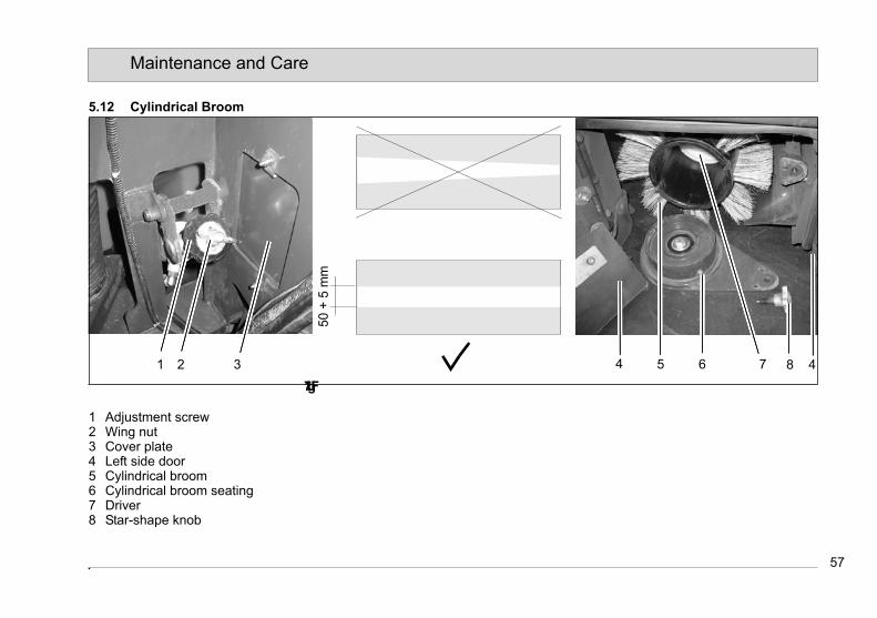
57
Maintenance and Care
5.12 Cylindrical Broom
Fig.17
1 Adjustment screw2 Wing nut3 Cover plate4 Left side door5 Cylindrical broom6 Cylindrical broom seating7 Driver8 Star-shape knob
50 +
5 m
m
1 2 6 73 4 5 8 4
57
Maintenance and Care
5.12 Cylindrical Broom
Fig.17
1 Adjustment screw2 Wing nut3 Cover plate4 Left side door5 Cylindrical broom6 Cylindrical broom seating7 Driver8 Star-shape knob
50 +
5 m
m
1 2 6 73 4 5 8 4

58
Maintenance and Care
5.12.1 Adjust Wearing Compensati-on of Cylindrical Broom
Check cylindrical broom (Fig. 17/5)for wearing at weekly intervals. In case of wearing or after replacement adjust the cylindrical broom as follows:1. Lower cylindrical broom on smooth
ground and let it run for a short time.2. Lift cylindrical broom and advance
vehicle a short distance.3. Turn engine off and engage parking
brake.4. Check wearing. If correctly adjusted,
the bristling of the cylindrical broom leaves a parallel pattern of 50 mm width on the floor, see sketch.
5. Remove cover plate (Fig. 17/3) and loosen wing nut (Fig. 17/2). Use ad-justment screw (Fig. 17/1) to correct sweeping pattern width.- Turn adjustment screw to the right:
widening sweeping pattern- Turn adjustment screw to the left:
narrowing sweeping pattern6. Counter-lock adjustment screw by
wing nut.
5.12.2 Adjust Parallelism of Cylindri-cal Broom
Parallelism of the cylindrical broom has been set in the factory. If sweeping pat-tern is out of parallel, re-adjust by screw (Fig. 18/1). Adjustment screw is located underneath the fan drive in the scrub-bing unit area.
Fig.18
1
59
Maintenance and Care
5.12.3 Change Cylindrical BroomIn case of wearing to a bristle length of minimal 35 mm, change cylindrical broom. Cylindrical broom is accessible from the left side (direction of travel) and can be removed as follows:1. Park vehicle on level ground.2. Lower cylindrical broom and set
broom ground pressure lever (Fig. 5/8) to lower position.
3. Turn engine off and engage parking brake.
4. Open left side door (Fig. 17/4).5. Remove star-shaped knob (Fig. 17/
8) and pull out cylindrical broom sea-ting (Fig. 17/6)
6. Pull out cylindrical broom (Fig. 17/5)7. Insert new cylindrical broom in inver-
se order.
Driver (Fig. 17/7) of the cylind-rical broom (inside) has to catch in drive. When fitting the cylindrical broom seating, both guide pins have to catch into the grooves of the broom as well.
5.12.4 Change Cylindrical Broom Apron
Check the cylindrical broom apron (Fig. 17/4) at the side doors at weekly inter-vals for wearing. Immediately replace worn aprons.1. Park vehicle on level ground. Turn
engine off and engage parking bra-ke.
2. Loosen plates, nuts and hexagonal screws and remove aprons.
3. Proceed to mounting of new cylindri-cal broom apron in inverse order.
4. Adjust ground clearance to approx. 3mm after fitting of the aprons.
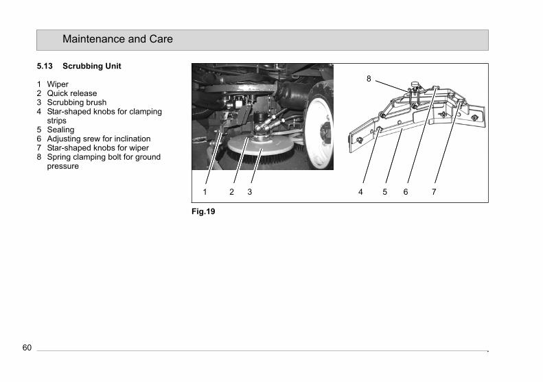
60
Maintenance and Care
5.13 Scrubbing Unit
1 Wiper2 Quick release3 Scrubbing brush4 Star-shaped knobs for clamping
strips5 Sealing6 Adjusting srew for inclination7 Star-shaped knobs for wiper8 Spring clamping bolt for ground
pressure
Fig.19
1 2 3 4 65 7
8
60
Maintenance and Care
5.13 Scrubbing Unit
1 Wiper2 Quick release3 Scrubbing brush4 Star-shaped knobs for clamping
strips5 Sealing6 Adjusting srew for inclination7 Star-shaped knobs for wiper8 Spring clamping bolt for ground
pressure
Fig.19
1 2 3 4 65 7
8

61
Maintenance and Care
5.13.1 Change Scrubbing BrushesCheck the scrubbing brushes (Fig. 19/3) for damages at weekly intervals. Re-place scrubbing brushes in case of wearing to a bristle length of minimal 15 mm. A quick release makes brush re-moval easy.1. Park vehicle on level ground.2. Switch off scrubbing unit.3. Open engine frame,siehe Abschnitt
5.5.1.4. Push the quick release(Fig. 19/2)
from the scrubbing brush. Remove old scrubbing brush.
5. Install new scrubbing brush in inver-se order.
5.13.2 Change SealsCheck seals (Fig. 19/5) for wearing at weekly intervals. 2-fold use of the sealing strips is possible by turning strips round.1. Park vehicle on level ground.2. Switch off scrubbing unit3. Turn engine off and engage parking
brake.4. Loosen star-shaped knobs for wiper
(Fig. 19/6) and remove together with wiper.
5. Loosen star-shaped knobs for clam-
ping strips (Fig. 19/4) Remove clam-ping strips and sealing.
6. Turn sealing round or change if re-quired (If turning of sealing strip is not possible due to its asymmetrical shape use sealing strip on the other side of machine).
7. Install wipers in inverse order.
5.13.3 Adjust wiperParallel to the floor:
Use adjustment screws (Fig. 19/6) to adjust the wiper in parallel to the floor. Turn adjustment screw clockwise to lift up wiper and counter-clockwise to lo-wer the wiper.Ground pressure:
By increasing the spring tension via spring clamping bolt (Fig. 19/8), the pressure acting on the sealing strip and thus on the floor will raised. This higher force is used for all cases of rough or uneven floors and surfaces. Softer sur-faces require less strong ground pres-sure

62
Maintenance and Care
5.14 Squeegee
1 Squeegee2 Squeegee lift-out3 Sealing4 Star-shaped knobs for squeegee5 Clamp6 Star-shaped knobs for seal7 Support rollers8 Star-shaped knobs for support roller9 Wing screws10 Inclination adjustment screws
Fig.20
1 2 3 4 5 6
7
8
9
10
62
Maintenance and Care
5.14 Squeegee
1 Squeegee2 Squeegee lift-out3 Sealing4 Star-shaped knobs for squeegee5 Clamp6 Star-shaped knobs for seal7 Support rollers8 Star-shaped knobs for support roller9 Wing screws10 Inclination adjustment screws
Fig.20
1 2 3 4 5 6
7
8
9
10

63
Maintenance and Care
5.14.1 Remove Squeegee1. Park vehicle on level ground.2. Turn engine off and engage parking
brake.3. Loosen star-shaped knobs for
squeegee (Fig. 20/4) and pull squee-gee (Fig. 20/1) to the rear for remo-val.
4. Proceed to fitting in inverse order.
5.14.2 Change SealsCheck seals (Fig. 20/3) for wearing at weekly intervals. 2-fold use of the sealing strips is possible by turning in-ner strips round. By turning the outer strips round even 4-fold use is possible.
Remove seals without tools as follows:1. Open clamps (Fig. 20/5) and remove
star-shaped knobs (Fig. 20/6) and wing screws (Fig. 20/9). Remove seals (Fig. 20/3).
2. Turn seals round or change as requi-red.
3. Proceed to fitting in inverse order.4. Adjust sealing strips straight and in
parallel to squeegee body.
5.14.3 Adjust SqueegeeParallel adjustment
1. Park vehicle on level ground.2. Turn engine off and engage parking
brake.3. Check sealing strips for straight fi-
xing in parallel to the squeegee bo-dy. Re-align sealing strips to parallel if required.
4. Before parallel adjustment of the squeegee, loosen the adjustment screws before and behind the plate on the threaded rod (Fig. 20/10) and unscrew them each 10mm away from the plate.
5. Start engine and lower squeegee. The squeegee aligns in parallel to the floor upon lowering. The sealing strips then should stand vertically and must not bend.
6. Fix this position with adjustment screws (Fig. 20/10) by screwing clo-ser to the plate and tightening of the nuts.
7. Check parallelism by riding forward with lowered squeegee. The sealing strips at the centre and at the border of the squeegee should evenly and lightly bend to the rear.
Adjust height
1. Park vehicle on level ground and en-gage parking brake.
2. Start engine and lower squeegee. Make sure that the sealing strips stand vertically and do not bend.
3. Loosen both support rollers (Fig. 20/7) of squeegee lift-out by means of star-shaped knobs (Fig. 20/8).
4. Use washers to adjust support rol-lers until clearance between rollers and floor amounts to 5 to 7mm.
5. Tighten both knobs again.6. Check correct height by riding in
working mode with use of water.If the rear squeegee will be partly torn to the front by low pressure, cor-rect adjustment by lowering squee-gee.If heavy noise is occurring, correct adjustment by lifting squeegee.
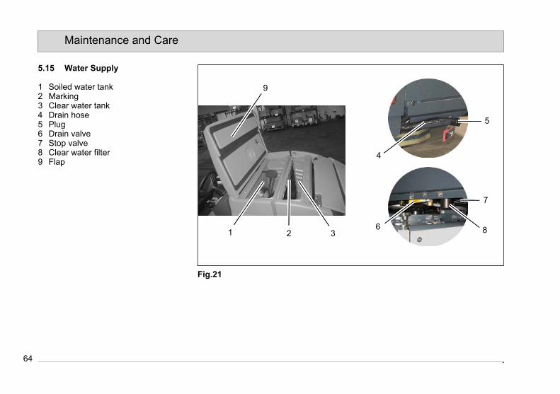
64
Maintenance and Care
5.15 Water Supply
1 Soiled water tank2 Marking3 Clear water tank4 Drain hose5 Plug6 Drain valve7 Stop valve8 Clear water filter9 Flap
Fig.21
1 2 3
4
5
6
7
8
9
64
Maintenance and Care
5.15 Water Supply
1 Soiled water tank2 Marking3 Clear water tank4 Drain hose5 Plug6 Drain valve7 Stop valve8 Clear water filter9 Flap
Fig.21
1 2 3
4
5
6
7
8
9

65
Maintenance and Care
5.15.1 Fill Clear Water TankFill the clear water tank (Fig. 21/1) as required or upon lighting of the pilot lamp at the latest. Park vehicle on level ground and engage parking brake.Open flap (Fig. 21/9) and fill clear water tank up to maximum marking (Fig. 21/2).
5.15.2 Drain Clear WaterPark vehicle such that the drain valve (Fig. 21/6) is located above discharge point. Turn drain valve by 90° to open.
5.15.3 Clean Clear water filterClean clear water filter (Fig. 21/8) at daily intervals and check for damages. Change clear water filter if required. Cleaning and changing the clear water filter is possible even with filled clear water tank.1. Turn stop valve (Fig. 21/7) by 90° to
close.2. Unscrew filter housing.3. Take filter element from housing and
clean. If required change filter ele-ment.
4. Re-install filter element and housing.5. Re-open stop valve.
5.15.4 Empty Soiled Water TankEmpty the soiled water tank (Fig. 21/1) as required or upon lighting of the pilot lamp at the latest. Park vehicle on level ground and engage parking brake.1. Ride to appropriate cleaning site and
park vehicle such that the drain hose reaches to the discharge point.
Provide for eco-friendly dispo-sal of soiled water!
2. Turn machine off and engage par-king brake.
3. Take drain hose (Fig. 21/4) from hol-der and kink flexible hose end to block water flow. Then remove drain plug (Fig. 21/5). The flexible hose end allows dosage of drain flow.
4. Completely drain soiled water tank.
5.15.5 Clean Soiled Water TankClean soiled water tank (Fig. 21/1) at daily intervals.1. Empty soiled water tank, siehe Ab-
schnitt 5.15.42. Remove both large caps (Fig. 6/20)
of the soiled water tank.3. Take drain hose (Fig. 21/4) from hol-
der and place on appropriate point on the floor for draining.
4. Then remove drain plug (Fig. 21/5).5. Use clear water to clean the soiled
water tank and rinse dirt through all opening.
6. Screw cap again.7. Rinse drain hose as well.8. Hinge drain hose again.
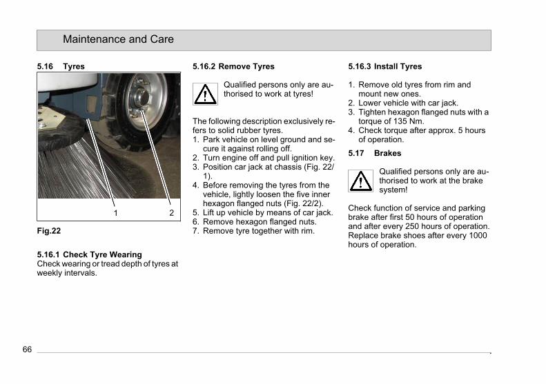
66
Maintenance and Care
5.16 Tyres
Fig.22
5.16.1 Check Tyre WearingCheck wearing or tread depth of tyres at weekly intervals.
5.16.2 Remove Tyres
Qualified persons only are au-thorised to work at tyres!
The following description exclusively re-fers to solid rubber tyres.1. Park vehicle on level ground and se-
cure it against rolling off.2. Turn engine off and pull ignition key.3. Position car jack at chassis (Fig. 22/
1).4. Before removing the tyres from the
vehicle, lightly loosen the five inner hexagon flanged nuts (Fig. 22/2).
5. Lift up vehicle by means of car jack.6. Remove hexagon flanged nuts.7. Remove tyre together with rim.
5.16.3 Install Tyres
1. Remove old tyres from rim and mount new ones.
2. Lower vehicle with car jack.3. Tighten hexagon flanged nuts with a
torque of 135 Nm.4. Check torque after approx. 5 hours
of operation.
5.17 Brakes
Qualified persons only are au-thorised to work at the brake system!
Check function of service and parking brake after first 50 hours of operation and after every 250 hours of operation.Replace brake shoes after every 1000 hours of operation.
21
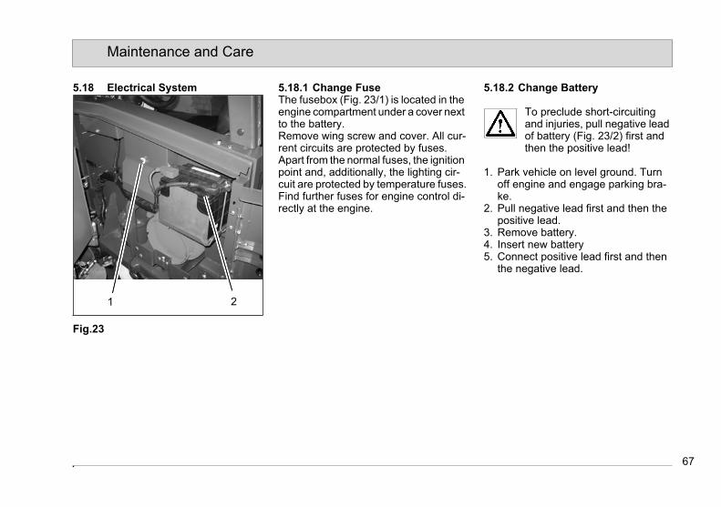
67
Maintenance and Care
5.18 Electrical System
Fig.23
5.18.1 Change FuseThe fusebox (Fig. 23/1) is located in the engine compartment under a cover next to the battery.Remove wing screw and cover. All cur-rent circuits are protected by fuses. Apart from the normal fuses, the ignition point and, additionally, the lighting cir-cuit are protected by temperature fuses.Find further fuses for engine control di-rectly at the engine.
5.18.2 Change Battery
To preclude short-circuitingand injuries, pull negative lead of battery (Fig. 23/2) first and then the positive lead!
1. Park vehicle on level ground. Turn off engine and engage parking bra-ke.
2. Pull negative lead first and then the positive lead.
3. Remove battery.4. Insert new battery5. Connect positive lead first and then
the negative lead.
21

Hakomatic 1800 V/LPG/DChanges Due to Machine Directive 2006/42/EC Clean ahead
PrefaceModified text in paragraph Preface:Before using the equipment for the first time, read this original manual thor-oughly, act according to the information contained and keep it in a safe place for future reference or subsequent owners.Intended useModified text in paragraph Intended Use:Based on the conception, design and construction of the model introduced onto the market by us, the machine complies with the applicable basic safe-ty and health requirements stipulated in the EC Directive (refer to Declaration of Conformity). This declaration is no long-er considered valid in the event of mod-ifications to the machine not authorized by us. The manufacturer is not deemed liable for any damage resulting from un-authorized modifications to the ma-chine.General safety informationThe machine may be used only for operation on plane areas with a maxi-mum inclination of up to 13 %.
DisposalNew text in Chapter Introduction:Render the machine inoperable. It must not represent a potential source of dan-ger for children.Dispose of the device according to the applicable local regulations. For further information on handling and recycling, please contact your authorized Hako dealer where you purchased the de-vice.Used batteries with the recycling sym-bol contain reusable commodities. The heavy metals contained simultaneously represent a serious risk to health and to the environment. Never open batteries or damage them. Never touch, inhale or swallow any material inside batteries. Health hazard! Never allow batteries to pollute the environment. Risk of con-taminating the ground and water! In ac-cordance with the symbol with the crossed out bin, these batteries must not be disposed of in domestic waste. The return and recycling of old batteries must be agreed on with your authorized Hako dealer in accordance with the Bat-tery Law § 6 and § 8 (BattG)
Noise emission valueThe sound pressure level (LpA) (at the ear of the operator) measured accord-ing to DIN IEC 60335-2-72 under nor-mal working conditions: 83 dB (A)Measurement inaccuracy (KpA): 2 dB (A)Sound power level (LwAd) measured according to DIN EN 60335-2-72 under maximum working conditions: 99 dB (A)
VibrationThe weighted effective value of acceler-ation, measured in accordance with ISO 5349-1, to which the upper parts of the body (hand-arm) are exposed under normal working conditions: < 2,5 m/s²The weighted effective value of acceler-ation, measured in accordance with ISO 2631-1, to which the upper parts of the body (feet-seat) are exposed under normal working conditions: < 0,5 m/s²

Hako GmbHHamburger Straße 209-239D-23843 Bad Oldesloe
declares that the products
Hakomatic 1800 V, Typ: 7574.10Hakomatic 1800 LPG, Typ: 7574.20Hakomatic 1800 D, Typ: 7574.30
to which this declaration relates, con-form to the relevant provisions of the safety and health requirements stipulat-ed in EC Directive 2006/42/EC and is in accordance with 2004/108/EC.
Reference was made to the following standards and/or norms and/or techni-cal specifications to ensure proper im-plementation of the safety and health requirements in the EC Directive:
EN 60335-2-72EN 55012EN 61000-6-2
Bad Oldesloe, 27.10.2010
Dr. Rainer BavendiekDirector R&D
Name of the authorized person who compiles technical documents for Hako:
Ludger Lüttel
EC Declaration of Conformity (corresponds to EC Directive 2006/42/EC)
Hako-Werke GmbHHamburger Straße 209-239D-23843 Bad Oldesloe
declares that the products
Hakomatic 1800 V, Typ: 7574.10Hakomatic 1800 LPG, Typ: 7574.20Hakomatic 1800 D, Typ: 7574.30
to which this declaration relates, con-form to the relevant provisions of the safety and health requirements stipulat-ed in EC Directive 2006/42/EC and is in accordance with 2004/108/EC.
Reference was made to the following standards and/or norms and/or techni-cal specifications to ensure proper im-plementation of the safety and health requirements in the EC Directive:
EN 60335-2-72EN 55012EN 61000-6-2
Bad Oldesloe, 27.10.2010
Dr. Rainer BavendiekDirector R&D
Name of the authorized person who compiles technical documents for Hako:
Ludger Lüttel
EC Declaration of Conformity (corresponds to EC Directive 2006/42/EC)
Spitzentechnik für einesaubere und schönere UmweltSuperior technology for a cleaner and better environment
Hako GmbH · Hamburger Str. 209-239 · D-23843 Bad Oldesloe · (04531) 806-0 · Fax (04531) 806-338
88-1
0-27
14/1
1-20
10 •
Prin
ted
in G
erm
any
Spitzentechnik für einesaubere und schönere UmweltSuperior technology for a cleaner and better environment
Hako-Werke GmbH · Stammwerk und Hauptverwaltung · HeadquarterHamburger Str. 209-239 · D-23843 Bad Oldesloe · (04531) 806-0 · Fax (04531) 806-338
88-6
0-27
14/1
1-20
10 •
Prin
ted
in G
erm
any