instruction manual - a-m systems · instruction manual for intracellular electrometer ... it comes...
TRANSCRIPT

INSTRUCTION MANUAL
FOR
Intracellular Electrometer
MODEL 3100
Serial #__________
Date____________
A-M Systems, Inc.PO Box 850
Carlsborg, WA 98324U.S.A.
360-683-8300 800-426-1306FAX: 360-683-3525
http://www.a-msystems.com
Version 2.0October 2001

NOTE
This instrument is not intended for clinical measurements using humansubjects. A-M Systems, Inc. does not assume responsibility for injury or
damage due to the misuse of this instrument.
Each Intracellular Electrometeris delivered complete with:
One Head Stage with 5 Foot CableRack Mount Hardware
Instruction ManualPower Supply Cord
Power Supply
ContentsGeneral Description ............................................................................................................................ 1Instrument Features ............................................................................................................................................ 1Controls and Connectors ..................................................................................................................................... 3Operating Instructions ......................................................................................................................... 7Typical Set-Up Procedure ................................................................................................................................... 7Headstage and Microelectrode Operation .......................................................................................................... 8Electrode Calibration ......................................................................................................................................... 10Current Injection ................................................................................................................................................ 11 Problem Solving ............................................................................................................................................... 12Specifications ..................................................................................................................................... 13Current Input ..................................................................................................................................................... 13Current Injection ............................................................................................................................................... 13Current Gate ..................................................................................................................................................... 13Electrode Test ................................................................................................................................................... 13Signal Processing .............................................................................................................................................. 14Outputs .............................................................................................................................................................. 15Physical Dimensions ......................................................................................................................................... 15Warranty and Service ........................................................................................................................ 16
1A-M Systems 131 Business Park Loop, P.O. Box 850 Carlsborg, Wa 98324Telephone: 800-426-1306 * 360-683-8300 * FAX: 360-683-3525E-mail: [email protected] * Website: http://www.a-msystems.com
General Description
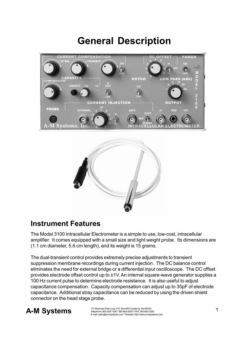
Instrument FeaturesThe Model 3100 Intracellular Electrometer is a simple to use, low-cost, intracellularamplifier. It comes equipped with a small size and light weight probe. Its dimensions are(1.1 cm diameter, 5.6 cm length), and its weight is 15 grams.
The dual-transient control provides extremely precise adjustments to transientsuppression membrane recordings during current injection. The DC balance controleliminates the need for external bridge or a differential input oscilloscope. The DC offsetprovides electrode offset control up to ±1V. An internal square-wave generator supplies a100 Hz current pulse to determine electrode resistance. It is also useful to adjustcapacitance compensation. Capacity compensation can adjust up to 35pF of electrodecapacitance. Additional stray capacitance can be reduced by using the driven shieldconnector on the head stage probe.
2A-M Systems 131 Business Park Loop, P.O. Box 850 Carlsborg, Wa 98324Telephone: 800-426-1306 * 360-683-8300 * FAX: 360-683-3525E-mail: [email protected] * Website: http://www.a-msystems.com
The Model 3100 has an advanced capacitance "Ringer" control for clearing electrodestips and enhancing the membrane penetration of neurons. The Ringer's amplitude (0-10Vbiphasic) and frequency (2-8kHz) of the pulsed oscillations that are sent to the electrodecan be adjusted on the front panel.
A six-position, low-pass filter and a 60 Hz notch filter are available for the researcher todiminish extraneous frequencies and external line noise.
The current injection systems allows for both internally generated current and externallygenerated current. This current can be set for continuous or momentary injection. Thesum of the current can be gated by an external TTL logic signal source.
The small size of the amplifier and its remote power supply offer the advantage of placingthe amplifier near to the experimental set up. For example, the amplifier can be placedwithin a Faraday cage with minimal power-line interference.

3A-M Systems 131 Business Park Loop, P.O. Box 850 Carlsborg, Wa 98324Telephone: 800-426-1306 * 360-683-8300 * FAX: 360-683-3525E-mail: [email protected] * Website: http://www.a-msystems.com
Controls and Connectors
POWERThis toggle switch is the power switch controlling the DC powerinput to the main circuit of the instrument. The led to the right of theswitch is lit when the instrument is ON. This switch does not controlthe AC power input to the remote international power supply.
DC OFFSETDC OFFSET KNOB: This knob sets the variable DCoffset voltage, which is summed with the inputvoltage. This feature may be used to compensate forelectrode potentials and to position the signal traceon an oscilloscope recording device. An offset rangeof 0.0 V to ±1.0 V is available at the X1 OUTPUT and0.0 V to ±10 V at the X10 OUTPUT.
DC OFFSET SWITCH (+ OFF -): This switch sets the DCoffset polarity or alternately turns the feature OFF.
CURRENT COMPENSATION
ON-OFF: This knob will turn current compensation on or off. The off position is thepreferred setting for any experiment not involving current injection, as the balance circuitcreates a slight increase in noise level.
TRANSIENT: These two knobs form a dual-function transient control which adjusts thetransient response of the balance circuit to duplicate that of the Headstage Probe,allowing maximum suppression of the transient when balancing out the electroderesponse for current injection. The left knob controls one time constant that effects theslope of the waveform, while the right knob will effect the peaks of the waveform. Theeffect of both controls is increased as they are rotated clockwise.
DC BAL: This knob controls a potentiometer which nulls voltage drop across the electrodedue to current injection when recording and stimulating through the same electrode.
4A-M Systems 131 Business Park Loop, P.O. Box 850 Carlsborg, Wa 98324Telephone: 800-426-1306 * 360-683-8300 * FAX: 360-683-3525E-mail: [email protected] * Website: http://www.a-msystems.com
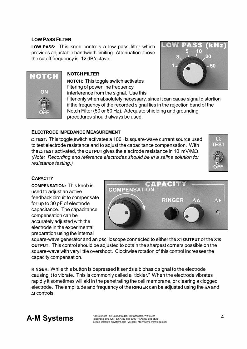
LOW PASS FILTERLOW PASS: This knob controls a low pass filter whichprovides adjustable bandwidth limiting. Attenuation abovethe cutoff frequency is -12 dB/octave.
NOTCH FILTERNOTCH: This toggle switch activatesfiltering of power line frequencyinterference from the signal. Use thisfilter only when absolutely necessary, since it can cause signal distortionif the frequency of the recorded signal lies in the rejection band of theNotch Filter (50 or 60 Hz). Adequate shielding and groundingprocedures should always be used.
ELECTRODE IMPEDANCE MEASUREMENT TEST: This toggle switch activates a 100 Hz square-wave current source usedto test electrode resistance and to adjust the capacitance compensation. Withthe TEST activated, the OUTPUT gives the electrode resistance in 10 mV/M.(Note: Recording and reference electrodes should be in a saline solution forresistance testing.)
CAPACITYCOMPENSATION: This knob isused to adjust an activefeedback circuit to compensatefor up to 30 pF of electrodecapacitance. The capacitancecompensation can beaccurately adjusted with theelectrode in the experimentalpreparation using the internalsquare-wave generator and an oscilloscope connected to either the X1 OUTPUT or the X10OUTPUT. This control should be adjusted to obtain the sharpest corners possible on thesquare-wave with very little overshoot. Clockwise rotation of this control increases thecapacity compensation.
RINGER: While this button is depressed it sends a biphasic signal to the electrodecausing it to vibrate. This is commonly called a “tickler.” When the electrode vibratesrapidly it sometimes will aid in the penetrating the cell membrane, or clearing a cloggedelectrode. The amplitude and frequency of the RINGER can be adjusted using the A andf controls.
5A-M Systems 131 Business Park Loop, P.O. Box 850 Carlsborg, Wa 98324Telephone: 800-426-1306 * 360-683-8300 * FAX: 360-683-3525E-mail: [email protected] * Website: http://www.a-msystems.com
A: This knob adjusts the amplitude of the ringer signal from 0 to 10V. Clockwise rotationincreases the amplitude.
Df: This knob adjusts the frequency of oscillations of the ringer signal between 2 and 8kHz. Clockwise rotation increases the frequency of the signal.
CURRENT INJECTION
EXTERNAL: This BNC connector provides control over the magnitude of the injectedcurrent via an external signal applied at this input. The current applied here is summedwith the current set by the µA knob. Sensitivity is 100 nA/V. Current injection is triggeredvia the CURRENT INJECTION (CONT-OFF-MOMEN) switch or the CURRENT GATE connector.
CURRENT GATE: This BNC connector provides control over the timing of current injection.A signal greater than +2.5 V (optimal results will be obtained with a signal of +5 V) at thisinput triggers injection of the preset current and a signal less than +0.6 V (optimal resultswill be obtained with a signal of 0.0 V) turns the injection current off. When not connected,the current gate is in an off state and current gating is manually controlled via the CURRENTINJECTION (CONT-OFF-MOMEN) switch.
CURRENT INJECTION (CONT-OFF-MOMEN): This switch triggers injection of the presetinjection current. The CONT setting triggers continuous current injection which lasts untilthe switch is manually returned to the OFF position. The MOMEN setting triggers continuouscurrent injection which lasts only as long as the switch is held in this position. The switchwill automatically return to the OFF position after being released from the MOMEN position.
µA: This knob sets the level of the injection current supplied by the internal source.
+,-: This switch sets the output polarity of the internal current source.

6A-M Systems 131 Business Park Loop, P.O. Box 850 Carlsborg, Wa 98324Telephone: 800-426-1306 * 360-683-8300 * FAX: 360-683-3525E-mail: [email protected] * Website: http://www.a-msystems.com
HEADSTAGE PROBE INPUTPROBE: This mini-din connector receives the input signal from theHeadstage Probe.
OUTPUTSX1 OUTPUT: This BNC connectorprovides the measured signal (plus anyDC offset) for recording on a chart recorder oroscilloscope.
X10 OUTPUT: This BNC connector provides 10 timesthe measured signal (plus any DC offset) for recordingon a chart recorder or oscilloscope.
GND: This connector provides a ground or reference point for measuring probe potential.
REAR PANELPOWER INPUT: This DIN connector is used to connect the international powersupply to the Model 3100 Intracellular Electrometer.

7A-M Systems 131 Business Park Loop, P.O. Box 850 Carlsborg, Wa 98324Telephone: 800-426-1306 * 360-683-8300 * FAX: 360-683-3525E-mail: [email protected] * Website: http://www.a-msystems.com
Operating Instructions
Typical Set-Up ProcedureThis is a generalized procedure for setting up the Intracellular Electrometer Model 3100for intracellular recording and stimulation. Portions of this procedure may need to bemodified for your specific application.
1. Connect the Headstage Probe cable to the PROBE connector.
2. Set the instrument controls as follows:
DC OFFSET knob counterclockwiseDC OFFSET (+ OFF -) OFFTRANSIENTS: counterclockwiseDC BALANCE counterclockwiseLOW PASS 50kHZNOTCH FILTER OFF TEST OFFCAPACITY COMP. counterclockwiseCURRENT INJECTION (CONT-OFF-MOMEN) OFFµA counterclockwise
3. Turn on power to the Model 3100 and allow it to warm up for 5 minutes.
4. Mount a micropipette in a micropipette half-cell type holder, which in turn is connectedto the Headstage. Clamp the Headstage in a micromanipulator.
5. Connect the reference electrode to the GND connector.
6. Connect an oscilloscope to either the X1 or X10 OUTPUT, with the horizontal sweeprate set to 2ms/division.
7. Dip the micropipette and the reference electrode into a beaker of physiological salinesolution (or the solution in which the tissue will be bathed). The solution should havethe same temperature and ionic strength as that in which measurements will bemade. Note: immerse the micropipette to approximately the same depth as will beused during the measurement.
8. Observe the offset potential between the two electrodes displayed on theoscilloscope. Set the DC OFFSET (+ OFF -) switch to the appropriate polarity and adjustthe DC OFFSET knob to zero the digital display and amplifier outputs.
9. Switch on the TEST button to inject a 100 Hz square-wave current through theelectrode. The X1 OUTPUT now indicates electrode resistance in 10mV/M.
10. Adjust the oscilloscope for a good display of the square-wave.

8A-M Systems 131 Business Park Loop, P.O. Box 850 Carlsborg, Wa 98324Telephone: 800-426-1306 * 360-683-8300 * FAX: 360-683-3525E-mail: [email protected] * Website: http://www.a-msystems.com
11. Increase the CAPACITY COMPENSATION to “square-up” the corners of the waveform.Avoid overcompensation, which will cause ringing, excessive noise, and highfrequency oscillation.
12. Turn off the TEST button to stop the test signal.
14. Set the CURRENT INJECTION +/- switch to the desired current polarity and adjust the µAknob to the maximum current level which will be injected during the experiment.
15. Connect the current gating signal to the CURRENT INJECTION GATE input and adjust thesignal source for a repetitive waveform with a pulse duration similar to that which willbe used in the experiment.
16. Adjust the DC BALANCE knob to remove the electrode voltage drop from the outputsignal.
17. Adjust the TRANSIENT controls to minimize transients occurring when the current isgated on and off.
18. If the injection current magnitude is to be controlled by an external signal, connect thissignal to the EXTERNAL connector. Remember this signal will be summed with thesetting of the CURRENT knob. The current is injected only when triggered by theCURRENT INJECTION (CONT-OFF-MOMEN) switch or by the signal applied to the CURRENTGATE input.
19. Connect the desired recording device to the output connector(s).
20. Apply the electrodes to the experimental preparations.
21. If needed, connect an electrode shield to the driven shield ring on the Headstage.
22. Apply the LOW PASS filter and NOTCH FILTER if necessary.
Headstage and Microelectrode Operation
HEADSTAGE CABLE CONNECTIONSThe Headstage cable is connected to the PROBE connector on the front panel of theinstrument. Note: Always connect and disconnect the PROBE cable with the POWEROFF.
HEADSTAGE CARETo preserve the high input impedance, the connector end of the headstage must be keptmeticulously clean and dry. Contamination on the insulation between the input connector,driven shield and case (even from contact with fingers) can cause current leakageparticularly in the humid environment surrounding most experimental preparations. Usetissue paper to wipe this area clean and ensure that all micropipette holders are cleanand dry before attaching them to the Headstage. Also, observe the ±10 V limit at theHeadstage input. The input FET is protected against static charge however there is noovervoltage protection since such circuitry would result in a loss of input impedance. Beparticularly careful near high voltage stimulators.

9A-M Systems 131 Business Park Loop, P.O. Box 850 Carlsborg, Wa 98324Telephone: 800-426-1306 * 360-683-8300 * FAX: 360-683-3525E-mail: [email protected] * Website: http://www.a-msystems.com
MOUNTING MICROPIPETTESThe easiest way to mount a micropipette is with ahalf-cell type holder (Catalog #’s 641000-646500).This holder should have a 0.08 inch (2.0 mm)diameter pin connector to fit the headstage. Fill theholder with the same solution as the micropipette,typically 3M KCl. Be sure there are no air gaps which could cause discontinuity in theelectrical connection between the micropipette and holder.
If the micropipette must have freedom of movement or “float,” as when recording frommoving muscle fibers, place the end of a thin chloride silver wire into the stem of a filledmicropipette, securing the wire at the open end of the pipette with a fast-drying cement.Solder the other end of the wire to 0.080 inch (2.0 mm) diameter pin connector (Catalog #521000). Coil the wire between the pipette and pin connector into spring. Insert the cleanand dry pin connector in the Headstage.
DRIVEN SHIELD AND GROUND CONNECTIONSThe Headstage circuitry is enclosed by a driven shield maintained at the same potentialas the input connectors, thus there is no electric field between the input connections andshield, and therefore, no capacitive shunting. This shield is brought out of the Headstagecase through the gold ring surrounding the input connector. This connecting ring may beused to extend the driven shield to the micropipette holder and micropipette. Shieldingthe electrode and holder is recommended since this portion of the circuit is particularlysensitive to stray electric fields, due to the high impedance of the electrode tip and theHeadstage input. Using a driven shield for this purpose has the advantage of notintroducing any additional shunt capacitance nor a path for current leakage to ground.
A shield can be made from a coil of wire wrapped around the shield ring and extendedalong the length of the electrode holder and electrode. Foil or other conductive coatingson the electrode surface can also be used for shielding. Note: Make certain that thedriven shield does not contact either the Headstage case or the experimentalpreparation, as both are at ground or reference potential and such contact will preventproper circuit operation.
The Headstage case and GND connector are both connected to the circuit ground. Thiscan be used for connecting the reference electrode in situations where it is inconvenientto run a separate reference cable to the experimental preparation.
MOUNTING THE HEADSTAGE IN A MICROMANIPULATORThe Headstage should be clamped in the micromanipulator by means of the mounting rodattached to the end of the headstage.
Half Cell Holder # 6455

10A-M Systems 131 Business Park Loop, P.O. Box 850 Carlsborg, Wa 98324Telephone: 800-426-1306 * 360-683-8300 * FAX: 360-683-3525E-mail: [email protected] * Website: http://www.a-msystems.com
Electrode CalibrationTo inject currents and measure membrane potentials accurately, compensation must bemade for the characteristics of each individual electrode. Electrodes have three keyproperties: offset potential, resistance, and capacitance.
Any conductive material placed in an ionic solution has a potential with respect to thatsolution known as the half-cell potential. This potential is a function of the materialcomposition of the electrode, the ions in the solution, ionic activity, and temperature. Thepotential between two electrodes in a solution is equal to the difference between their half-cell potentials. Ideally, two identical electrodes should have zero potential between them,but small differences in surface properties usually are noticed as a small potentialdifference.
Most intracellular measurements are made with 3M KCI filled micropipettes which containor contact Ag/AgCl to form an electrolyte to metal junction. A second Ag/AgCl electrode isgenerally used as a reference. If the micropipette and reference electrodes are placed inphysiological saline, which duplicates the chloride concentration of most biological fluids,a potential difference will be observed. This potential occurs because the Ag/AgClelectrode in the micropipette “sees” the Cl concentration of the 3M KCl, which is muchhigher than that of the saline surrounding the reference electrode. There should be nosignificant potential due to concentration gradients at the electrode tip, since potassiumand chloride ions have approximately the same ionic mobilities. Thus, to accuratelymeasure the potential across a cell membrane, it is necessary to null the electrodepotential using the DC OFFSET control. Alternately, one may use an Ag/AgCl electrodesurrounded by 3M KCl as a reference electrode. To accomplish this, use an agar bridgeor standard pH reference electrode with an Ag/AgCl internal (Catalog # 5330).
The micropipette resistance, which normally ranges from 10 to several hundred M, isnormally of little concern for measuring potentials, due to the high input impedance of theModel 3100. However, when injecting currents through a recording electrode, voltagedrop will appear across the electrode resistance and be recorded along with themembrane response. Since the membrane response alone is desired, the electroderesponse must be subtracted from the signal. This is accomplished through the DCBALANCE.
The electrode also has capacitance, which is in parallel with the resistance. Thiscapacitance acts as a shunt which attenuates the higher frequency components of thesignal. The CAPACITY COMPENSATION is adjusted to accentuate these higher frequencies,thus compensating for the loss.
For current injection, it is also necessary to adjust the balance circuitry to compensate forthis capacitance. The waveform which is subtracted from the recorded signal must haveprecisely the same rise-time and shape as the electrode voltage drop, or a transientspike will be observed in the signal whenever injected current turns on or off. This

11A-M Systems 131 Business Park Loop, P.O. Box 850 Carlsborg, Wa 98324Telephone: 800-426-1306 * 360-683-8300 * FAX: 360-683-3525E-mail: [email protected] * Website: http://www.a-msystems.com
waveform is adjusted with the TRANSIENT controls. Note: some types of micropipettesexhibit nonlinear impedance characteristics. When these are severe, the amplifiercannot fully compensate for them and the result is a transient signal upon currentinjection. The magnitude and shape of this transient should be recorded during initialsetup, then later manually subtracted from the recorded signals to obtain the truemembrane response.
Current InjectionThe Model 3100 offers several options for controlling injection current to allow for avariety of experimental preparations.
The basic configuration requires no additional instrumentation. The injection currentmagnitude is established with the µA knob, and injection takes place when the CURRENTINJECTION (CONT-OFF-MOMEN) switch is set to either CONT or MOMEN. In the MOMENtaryposition, the current is injected only as long as the switch is held down. This mode ofstimulation is generally useful for sub threshold membrane conductivity studies usingcontinuous DC stimulation.
Most studies, however, require precise control of injection current pulse duration andrepetition rate in addition to magnitude. The easiest configuration for this type ofexperiment includes a function generator or another signal source to control the pulseduration and repetition rate, and the µA knob to set the injection current magnitude. Thesignal source is applied to the current GATE connector. This input requires a signalgreater than +2.5 V to turn the injection current on and less than +0.6 V to turn the injectioncurrent off. The maximum voltage limit for this connector is +15 V.
When external control of current magnitude is also required, a control signal may beapplied to the EXTERNAL current connector. The injection current is proportional to thevoltage of the control signal. The final injection current is obtained by adding the controlsignal current to any current set by the µA knob. Current switching remains under thecontrol of the CURRENT INJECTION (CONT-OFF-MOMEN) switch or the GATE connector asdiscussed above. When complete control over current magnitude and timing is desiredthrough only one signal, the CURRENT INJECTION (CONT-OFF-MOMEN) switch may be set toCONT and the µA knob rotated fully counterclockwise. These settings zero the internalcurrent source and provide continuous injection of the current applied to the EXTERNALcurrent connector. Thus, current magnitude, polarity, and duration are all controlled by thesignal applied to the EXTERNAL current connector, with current injection stopped when theinput signal is zero.
The current control capabilities of the Model 3100 may be combined in various ways tosimplify otherwise complex control situations. For example, if it is necessary to modulatethe amplitude of a train of current pulses, a pulse signal can be applied to the current GATEconnector which will establish the duration and repetition rate, while the amplitude
12A-M Systems 131 Business Park Loop, P.O. Box 850 Carlsborg, Wa 98324Telephone: 800-426-1306 * 360-683-8300 * FAX: 360-683-3525E-mail: [email protected] * Website: http://www.a-msystems.com
modulation signal (frequently a ramp or triangle waveform) is applied to the EXTERNALcurrent connector. As another example, if a continuous injection current, interrupted bypulses of differing magnitudes and polarity is desired, the base injection current level canbe established by the µA knob and the +/- switch. A signal applied at the EXTERNAL currentconnector can provide the pulses of differing magnitude and polarity which will besummed with the internal injection current source.
Problem SolvingIf the Model 3100 does not function properly, consult the following list which suggestssolutions to the most common problems. If you need further assistance, please contactcustomer service at A-M Systems, Inc. at the numbers listed in the footer of this manual.
Problem Cause / Solution
Excessive offset potential Instrument oscillates due to excessive capacitancecompensation. Turn CAPACITY COMPENSATIONcounterclockwise.
Incorrect potential reading Ensure that TEST is OFF, CURRENT INJECTIONis OFF, DC OFFSET and DC BALANCE are OFF orproperly adjusted. Also, see above.
Incorrect response to Electrode impedance may be too great for desiredinjected current current level. Also, see above.
Electrode impedance Excessive noise included in signal. Shield electrodesincorrect or unstable if necessary.
DC BALANCE cannot be set Check electrode impedance. Also, see above.
Transients cannot be Check setting of CAPACITY COMPENSATION also, somebalanced out transients are due to nonlinear electrode impedance
characteristics and cannot be fully corrected. Mostproblems are due to improper control settings. Seethe section “Typical Set-Up Procedure” in thismanual for further assistance.

13A-M Systems 131 Business Park Loop, P.O. Box 850 Carlsborg, Wa 98324Telephone: 800-426-1306 * 360-683-8300 * FAX: 360-683-3525E-mail: [email protected] * Website: http://www.a-msystems.com
Specifications
Current InputImpedance 1011 Capacitance Adjustable to zeroWorking range ± 2.5 VMaximum range ± 10 V
Current Injection
EXTERNAL SOURCEInput impedance 20 kFrequency range DC to 50 kHzmaximum current 100 nA/Vmaximum voltage lesser of ±10 V and
(± 2.5 x 10⁷ M)/(electrode resistance)
INTERNAL SOURCEcurrent range lesser of ± 1000 nA and
2.5 V/(electrode resistance)
Current GateON signal + 2.5 V (step with rise time 10 µsec)OFF signal + 0.6 VMaximum input ± 15 VInput impedance 20 k
Electrode TestSignal 100 Hz square wavescale factor (X1 OUTPUT) 10 nA peak-to-peak = 10 mV/M

14A-M Systems 131 Business Park Loop, P.O. Box 850 Carlsborg, Wa 98324Telephone: 800-426-1306 * 360-683-8300 * FAX: 360-683-3525E-mail: [email protected] * Website: http://www.a-msystems.com
Signal Processing
INPUT BIAS CURRENTOptimal Adjustable to zeroMaximum without adjustment 3 x 10-11 AmpDrift versus temperature 1 x 10-12 Amp/ºCDrift versus time 3 x 10-12 Amp/12 hours
FREQUENCY RESPONSEFrequency range DC to 50 kHz
RISE TIMESquare wave (500 mV) <10.0 µsec, 10% to 90%
(Compensation set for 10% overshoot)
ZERO STABILITYStability versus temperature 200 µV/ºCStability versus time 1 mV/12 hours
LOW PASS FILTERCut-off frequencies (-3dB) 1, 2, 5, 10, 20, and 50 kHzSlope -40 dB/decade
NOTCH FILTERCenter frequency 50 Hz or 60 Hz (factory preset)Q 10Rejection -50 dB
CAPACITANCE COMPENSATIONRange -4 pF to +30 pF
NOISE0 source 18 µV RMS (10 Hz to 50 kHz)1 M source 90 µV RMS (10 Hz to 50 kHz)20 M source 350 µV RMS (10 Hz to 50 kHz)
DC BALANCEup to 100 M

15A-M Systems 131 Business Park Loop, P.O. Box 850 Carlsborg, Wa 98324Telephone: 800-426-1306 * 360-683-8300 * FAX: 360-683-3525E-mail: [email protected] * Website: http://www.a-msystems.com
Outputs
X 1 OUTPUTVoltage gain 1.00 ± 0.1%Maximum voltage ± 10 VImpedance 220 DC Offset range 0.0 V to ± 1.0 V
X 10 OUTPUTVoltage gain 10.0 ± 1.0%Maximum voltage ± 10 VImpedance 220 DC Offset range 0.0 V to ± 10.0 V
Power source remote international power supply
Physical Dimensions
AMPLIFIERWidth 8.5 inches (22 cm)Height 4.25 inches (11 cm)Depth 2.5 inches (7 cm)Weight 4 lbs.
HEAD STAGE PROBEInput connector 0.08 inch (2.0 mm) female pin connectorCase diameter 0.45 inch (1.1 cm)Case length 2.20 inches (5.6 cm)Mounting rod diameter 0.22 inch (5.7 mm)Mounting rod length 3.75 inches (9.5 cm)Weight 0.5 ounces (15 g)Input cable 5 feet (1.5 m) Superflex silicone jacketed

16A-M Systems 131 Business Park Loop, P.O. Box 850 Carlsborg, Wa 98324Telephone: 800-426-1306 * 360-683-8300 * FAX: 360-683-3525E-mail: [email protected] * Website: http://www.a-msystems.com
Warranty and Service
LIMITED WARRANTY
What does this warranty cover?
A-M Systems, LLC (hereinafter, “A-M Systems”) warrants to the Purchaser that the Instrument,including cables, Headstage Probes and any other accessories shipped with the Instrument,(hereafterthe “hardware”) is free from defects in workmanship or material under normal use and service for theperiod of three (3) years. This warranty commences on the date of delivery of the hardware to thePurchaser.
What are the obligations of A-M Systems under this warranty?
During the warranty period, A-M Systems agrees to repair or replace, at its sole option, withoutcharge to the Purchaser, any defective component part of the hardware. To obtain warranty service,the Purchaser must return the hardware to A-M Systems or an authorized A-M Systems distributor inan adequate shipping container. Any postage, shipping and insurance charges incurred in shipping thehardware to A-M Systems must be prepaid by the Purchaser and all risk for the hardware shall remainwith purchaser until such time as A-M Systems takes receipt of the hardware. Upon receipt, A-MSystems will promptly repair or replace the defective unit, and then return the hardware (or itsreplacement) to the Purchaser, postage, shipping, and insurance prepaid. A-M Systems may usereconditioned or like new parts or units at its sole option, when repairing any hardware. Repairedproducts shall carry the same amount of outstanding warranty as from original purchase, or ninety (90)days which ever is greater. Any claim under the warranty must include a dated proof of purchase of thehardware covered by this warranty. In any event, A-M Systems liability for defective hardware islimited to repairing or replacing the hardware.
What is not covered by this warranty?
This warranty is contingent upon proper use and maintenance of the hardware by the Purchaser anddoes not cover batteries. Neglect, misuse whether intentional or otherwise, tampering with or altering

17A-M Systems 131 Business Park Loop, P.O. Box 850 Carlsborg, Wa 98324Telephone: 800-426-1306 * 360-683-8300 * FAX: 360-683-3525E-mail: [email protected] * Website: http://www.a-msystems.com
LIMITED WARRANTY, cont
What are the limits of liability for A-M Systems under this warranty?
A-M Systems shall not be liable for loss of data, lost profits or savings, or any special, incidental,consequential, indirect or other similar damages, whether arising from breach of contract, negligence, orother legal action, even if the company or its agent has been advised of the possibility of such damages, orfor any claim brought against you by another party. THIS EQUIPMENT IS NOT INTENDED FORCLINICAL MEASUREMENTS USING HUMAN SUBJECTS. A-M SYSTEMS DOES NOTASSUME RESPONSIBILITY FOR INJURY OR DAMAGE DUE TO MISUSE OF THISEQUIPMENT. Jurisdictions vary with regard to the enforceability of provisions excluding or limiting liabilityfor incidental or consequential damages. Check the provision of your local jurisdiction to find out whetherthe above exclusion applies to you.
This warranty allocates risks of product failure between the Purchaser and A-M Systems. A-M Systemshardware pricing reflects this allocation of risk and the limitations of liability contained in this warranty. Theagents, employees, distributors, and dealers of A-M Systems are not authorized to make modifications tothis warranty, or additional warranties binding on the company. Accordingly, additional statements such asdealer advertising or presentations, whether oral or written, do not constitute warranties by A-M Systemsand should not be relied upon. This warranty gives you specific legal rights. You may also have other rightswhich vary from one jurisdiction to another.
THE WARRANTY AND REMEDY PROVIDED ABOVE IS IN LIEU OF ALL OTHERWARRANTIES AND REMEDIES, WHETHER EXPRESS OR IMPLIED. A-M SYSTEMSDISCLAIMS THE WARRANTIES OF MERCHANTIBILITY AND FITNESS FOR A PARTICULARUSE, WITHOUT LIMITATION.

A-M Systems 3100 Manual DRW-5027902 rev 3Approved:
Revision HistoryRev Date Description2 6/30/06 Initial Document Control release3 4/28/10 DCR201200 Warranty and Company Info