instruction manual and parts list for a3d ... - imo pump · instruction manual covers imo pump...
TRANSCRIPT
INSTRUCTION MANUAL
AND
PARTS LIST
FOR
A3D SERIES PUMPS
WARNING
This Instruction Manual and General Instructions Manual SRM00046, should be read thoroughly prior to pump installation, operation or maintenance.
Manual No. SRM00038 Rev. 15 (12-0265) JUNE 2012
TM
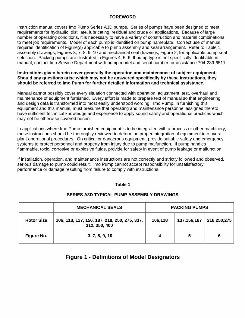
FOREWORD Instruction manual covers Imo Pump Series A3D pumps. Series of pumps have been designed to meet requirements for hydraulic, distillate, lubricating, residual and crude oil applications. Because of large number of operating conditions, it is necessary to have a variety of construction and material combinations to meet job requirements. Model of each pump is identified on pump nameplate. Correct use of manual requires identification of Figure(s) applicable to pump assembly and seal arrangement. Refer to Table 1, assembly drawings, Figures 3, 7, 8, 9, 10 and mechanical seal drawings, Figure 2, for applicable pump seal selection. Packing pumps are illustrated in Figures 4, 5, 6. If pump type is not specifically identifiable in manual, contact Imo Service Department with pump model and serial number for assistance 704-289-6511. Instructions given herein cover generally the operation and maintenance of subject equipment. Should any questions arise which may not be answered specifically by these instructions, they should be referred to Imo Pump for further detailed information and technical assistance. Manual cannot possibly cover every situation connected with operation, adjustment, test, overhaul and maintenance of equipment furnished. Every effort is made to prepare text of manual so that engineering and design data is transformed into most easily understood wording. Imo Pump, in furnishing this equipment and this manual, must presume that operating and maintenance personnel assigned thereto have sufficient technical knowledge and experience to apply sound safety and operational practices which may not be otherwise covered herein. In applications where Imo Pump furnished equipment is to be integrated with a process or other machinery, these instructions should be thoroughly reviewed to determine proper integration of equipment into overall plant operational procedures. On critical or dangerous equipment, provide suitable safety and emergency systems to protect personnel and property from injury due to pump malfunction. If pump handles flammable, toxic, corrosive or explosive fluids, provide for safety in event of pump leakage or malfunction. If installation, operation, and maintenance instructions are not correctly and strictly followed and observed, serious damage to pump could result. Imo Pump cannot accept responsibility for unsatisfactory performance or damage resulting from failure to comply with instructions.
Table 1
SERIES A3D TYPICAL PUMP ASSEMBLY DRAWINGS
MECHANICAL SEALS PACKING PUMPS
Rotor Size
106, 118, 137, 156, 187, 218, 250, 275, 337,
312, 350, 400
106,118
137,156,187
218,250,275
Figure No.
3, 7, 8, 9, 10
4
5
6
Figure 1 - Definitions of Model Designators
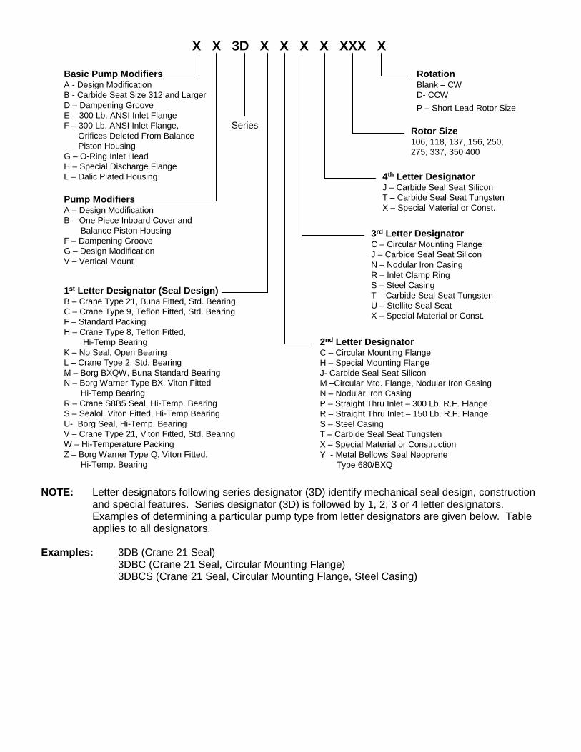
X X 3D X X X X XXX X
Basic Pump ModifiersA - Design Modification B - Carbide Seat Size 312 and LargerD – Dampening GrooveE – 300 Lb. ANSI Inlet FlangeF – 300 Lb. ANSI Inlet Flange,
Orifices Deleted From BalancePiston Housing
G – O-Ring Inlet HeadH – Special Discharge FlangeL – Dalic Plated Housing
Pump ModifiersA – Design ModificationB – One Piece Inboard Cover and
Balance Piston HousingF – Dampening GrooveG – Design ModificationV – Vertical Mount
RotationBlank – CWD- CCWP – Short Lead Rotor Size
Rotor Size106, 118, 137, 156, 250, 275, 337, 350 400
1st Letter Designator (Seal Design)B – Crane Type 21, Buna Fitted, Std. BearingC – Crane Type 9, Teflon Fitted, Std. BearingF – Standard PackingH – Crane Type 8, Teflon Fitted,
Hi-Temp BearingK – No Seal, Open BearingL – Crane Type 2, Std. BearingM – Borg BXQW, Buna Standard BearingN – Borg Warner Type BX, Viton Fitted
Hi-Temp BearingR – Crane S8B5 Seal, Hi-Temp. BearingS – Sealol, Viton Fitted, Hi-Temp BearingU- Borg Seal, Hi-Temp. BearingV – Crane Type 21, Viton Fitted, Std. BearingW – Hi-Temperature PackingZ – Borg Warner Type Q, Viton Fitted,
Hi-Temp. Bearing
4th Letter DesignatorJ – Carbide Seal Seat SiliconT – Carbide Seal Seat TungstenX – Special Material or Const.
3rd Letter DesignatorC – Circular Mounting FlangeJ – Carbide Seal Seat SiliconN – Nodular Iron CasingR – Inlet Clamp RingS – Steel CasingT – Carbide Seal Seat TungstenU – Stellite Seal SeatX – Special Material or Const.
2nd Letter DesignatorC – Circular Mounting FlangeH – Special Mounting FlangeJ- Carbide Seal Seat SiliconM –Circular Mtd. Flange, Nodular Iron Casing N – Nodular Iron CasingP – Straight Thru Inlet – 300 Lb. R.F. FlangeR – Straight Thru Inlet – 150 Lb. R.F. FlangeS – Steel CasingT – Carbide Seal Seat Tungsten X – Special Material or ConstructionY - Metal Bellows Seal Neoprene
Type 680/BXQ
Series
NOTE: Letter designators following series designator (3D) identify mechanical seal design, construction and special features. Series designator (3D) is followed by 1, 2, 3 or 4 letter designators. Examples of determining a particular pump type from letter designators are given below. Table applies to all designators.
Examples: 3DB (Crane 21 Seal) 3DBC (Crane 21 Seal, Circular Mounting Flange) 3DBCS (Crane 21 Seal, Circular Mounting Flange, Steel Casing)
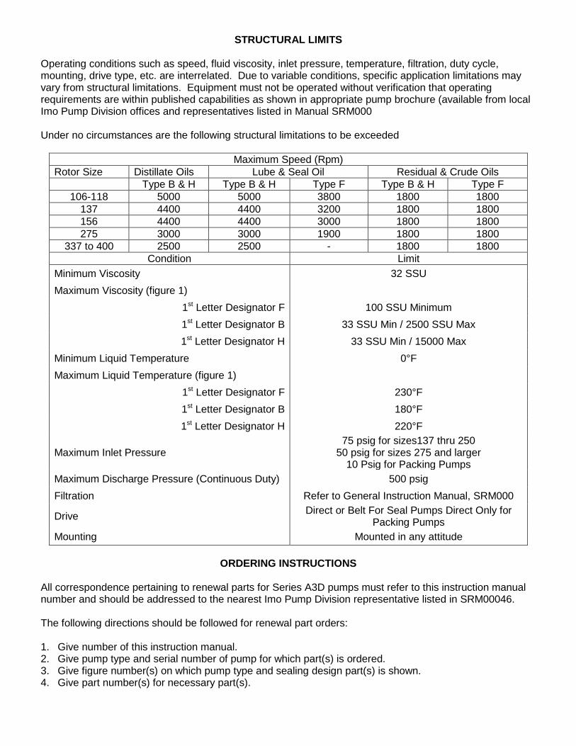
STRUCTURAL LIMITS
Operating conditions such as speed, fluid viscosity, inlet pressure, temperature, filtration, duty cycle, mounting, drive type, etc. are interrelated. Due to variable conditions, specific application limitations may vary from structural limitations. Equipment must not be operated without verification that operating requirements are within published capabilities as shown in appropriate pump brochure (available from local Imo Pump Division offices and representatives listed in Manual SRM000 Under no circumstances are the following structural limitations to be exceeded
Maximum Speed (Rpm) Rotor Size Distillate Oils Lube & Seal Oil Residual & Crude Oils Type B & H Type B & H Type F Type B & H Type F
106-118 5000 5000 3800 1800 1800 137 4400 4400 3200 1800 1800 156 4400 4400 3000 1800 1800 275 3000 3000 1900 1800 1800
337 to 400 2500 2500 - 1800 1800 Condition Limit
Minimum Viscosity 32 SSU Maximum Viscosity (figure 1)
1st Letter Designator F 100 SSU Minimum 1st Letter Designator B 33 SSU Min / 2500 SSU Max 1st Letter Designator H 33 SSU Min / 15000 Max
Minimum Liquid Temperature 0°F Maximum Liquid Temperature (figure 1)
1st Letter Designator F 230°F 1st Letter Designator B 180°F 1st Letter Designator H 220°F
Maximum Inlet Pressure 75 psig for sizes137 thru 250
50 psig for sizes 275 and larger 10 Psig for Packing Pumps
Maximum Discharge Pressure (Continuous Duty) 500 psig Filtration Refer to General Instruction Manual, SRM000
Drive Direct or Belt For Seal Pumps Direct Only for Packing Pumps
Mounting Mounted in any attitude
ORDERING INSTRUCTIONS All correspondence pertaining to renewal parts for Series A3D pumps must refer to this instruction manual number and should be addressed to the nearest Imo Pump Division representative listed in SRM00046. The following directions should be followed for renewal part orders: 1. Give number of this instruction manual. 2. Give pump type and serial number of pump for which part(s) is ordered. 3. Give figure number(s) on which pump type and sealing design part(s) is shown. 4. Give part number(s) for necessary part(s).
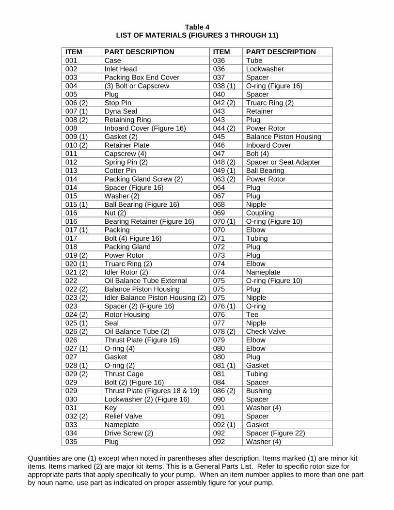
Table 4 LIST OF MATERIALS (FIGURES 3 THROUGH 11)
ITEM PART DESCRIPTION ITEM PART DESCRIPTION 001 Case 036 Tube 002 Inlet Head 036 Lockwasher 003 Packing Box End Cover 037 Spacer 004 (3) Bolt or Capscrew 038 (1) O-ring (Figure 16) 005 Plug 040 Spacer 006 (2) Stop Pin 042 (2) Truarc Ring (2) 007 (1) Dyna Seal 043 Retainer 008 (2) Retaining Ring 043 Plug 008 Inboard Cover (Figure 16) 044 (2) Power Rotor 009 (1) Gasket (2) 045 Balance Piston Housing 010 (2) Retainer Plate 046 Inboard Cover 011 Capscrew (4) 047 Bolt (4) 012 Spring Pin (2) 048 (2) Spacer or Seat Adapter 013 Cotter Pin 049 (1) Ball Bearing 014 Packing Gland Screw (2) 063 (2) Power Rotor 014 Spacer (Figure 16) 064 Plug 015 Washer (2) 067 Plug 015 (1) Ball Bearing (Figure 16) 068 Nipple 016 Nut (2) 069 Coupling 016 Bearing Retainer (Figure 16) 070 (1) O-ring (Figure 10) 017 (1) Packing 070 Elbow 017 Bolt (4) Figure 16) 071 Tubing 018 Packing Gland 072 Plug 019 (2) Power Rotor 073 Plug 020 (1) Truarc Ring (2) 074 Elbow 021 (2) Idler Rotor (2) 074 Nameplate 022 Oil Balance Tube External 075 O-ring (Figure 10) 022 (2) Balance Piston Housing 075 Plug 023 (2) Idler Balance Piston Housing (2) 075 Nipple 023 Spacer (2) (Figure 16) 076 (1) O-ring 024 (2) Rotor Housing 076 Tee 025 (1) Seal 077 Nipple 026 (2) Oil Balance Tube (2) 078 (2) Check Valve 026 Thrust Plate (Figure 16) 079 Elbow 027 (1) O-ring (4) 080 Elbow 027 Gasket 080 Plug 028 (1) O-ring (2) 081 (1) Gasket 029 (2) Thrust Cage 081 Tubing 029 Bolt (2) (Figure 16) 084 Spacer 029 Thrust Plate (Figures 18 & 19) 086 (2) Bushing 030 Lockwasher (2) (Figure 16) 090 Spacer 031 Key 091 Washer (4) 032 (2) Relief Valve 091 Spacer 033 Nameplate 092 (1) Gasket 034 Drive Screw (2) 092 Spacer (Figure 22) 035 Plug 092 Washer (4)
Quantities are one (1) except when noted in parentheses after description. Items marked (1) are minor kit items. Items marked (2) are major kit items. This is a General Parts List. Refer to specific rotor size for appropriate parts that apply specifically to your pump. When an item number applies to more than one part by noun name, use part as indicated on proper assembly figure for your pump.
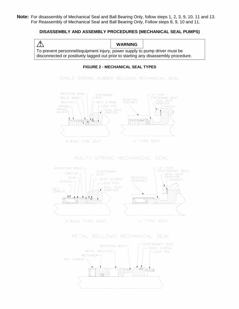
Note: For disassembly of Mechanical Seal and Ball Bearing Only, follow steps 1, 2, 3, 9, 10, 11 and 13. For Reassembly of Mechanical Seal and Ball Bearing Only, Follow steps 8, 9, 10 and 11.
DISASSEMBLY AND ASSEMBLY PROCEDURES (MECHANICAL SEAL PUMPS)
WARNING
To prevent personnel/equipment injury, power supply to pump driver must be disconnected or positively tagged out prior to starting any disassembly procedure.
FIGURE 2 - MECHANICAL SEAL TYPES
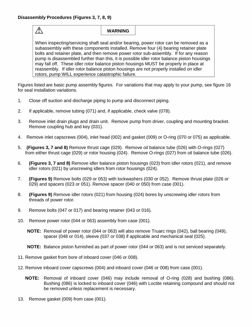
Disassembly Procedures (Figures 3, 7, 8, 9)
WARNING
When inspecting/servicing shaft seal and/or bearing, power rotor can be removed as a subassembly with these components installed. Remove four (4) bearing retainer plate bolts and retainer plate, and then remove power rotor sub-assembly. If for any reason pump is disassembled further than this, it is possible idler rotor balance piston housings may fall off. These idler rotor balance piston housings MUST be properly in place at reassembly. If idler rotor balance piston housings are not properly installed on idler rotors, pump WILL experience catastrophic failure.
Figures listed are basic pump assembly figures. For variations that may apply to your pump, see figure 16 for seal installation variations. 1. Close off suction and discharge piping to pump and disconnect piping. 2. If applicable, remove tubing (071) and, if applicable, check valve (078). 3. Remove inlet drain plugs and drain unit. Remove pump from driver, coupling and mounting bracket.
Remove coupling hub and key (031). 4. Remove inlet capscrews (004), inlet head (002) and gasket (009) or O-ring (070 or 075) as applicable. 5. (Figures 3, 7 and 8) Remove thrust cage (029). Remove oil balance tube (026) with O-rings (027)
from either thrust cage (029) or rotor housing (024). Remove O-rings (027) from oil balance tube (026). 6. (Figures 3, 7 and 8) Remove idler balance piston housings (023) from idler rotors (021), and remove
idler rotors (021) by unscrewing idlers from rotor housings (024). 7. (Figures 9) Remove bolts (029 or 053) with lockwashers (030 or 052). Remove thrust plate (026 or
029) and spacers (023 or 051). Remove spacer (040 or 050) from case (001). 8. (Figures 9) Remove idler rotors (021) from housing (024) bores by unscrewing idler rotors from
threads of power rotor. 9. Remove bolts (047 or 017) and bearing retainer (043 or 016). 10. Remove power rotor (044 or 063) assembly from case (001).
NOTE: Removal of power rotor (044 or 063) will also remove Truarc rings (042), ball bearing (049), spacer (048 or 014), sleeve (037 or 038) if applicable and mechanical seal (025).
NOTE: Balance piston furnished as part of power rotor (044 or 063) and is not serviced separately.
11. Remove gasket from bore of inboard cover (046 or 008). 12. Remove inboard cover capscrews (004) and inboard cover (046 or 008) from case (001).
NOTE: Removal of inboard cover (046) may include removal of O-ring (028) and bushing (086). Bushing (086) is locked to inboard cover (046) with Loctite retaining compound and should not be removed unless replacement is necessary.
13. Remove gasket (009) from case (001).
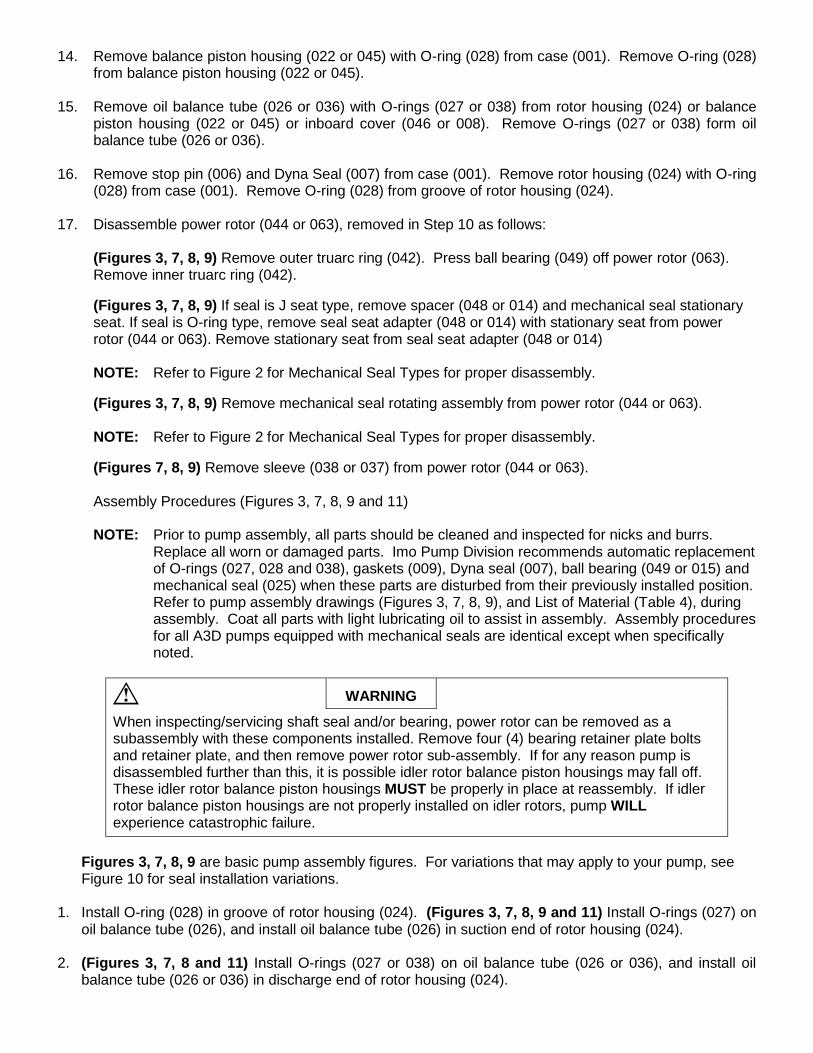
14. Remove balance piston housing (022 or 045) with O-ring (028) from case (001). Remove O-ring (028) from balance piston housing (022 or 045).
15. Remove oil balance tube (026 or 036) with O-rings (027 or 038) from rotor housing (024) or balance
piston housing (022 or 045) or inboard cover (046 or 008). Remove O-rings (027 or 038) form oil balance tube (026 or 036).
16. Remove stop pin (006) and Dyna Seal (007) from case (001). Remove rotor housing (024) with O-ring
(028) from case (001). Remove O-ring (028) from groove of rotor housing (024). 17. Disassemble power rotor (044 or 063), removed in Step 10 as follows:
(Figures 3, 7, 8, 9) Remove outer truarc ring (042). Press ball bearing (049) off power rotor (063). Remove inner truarc ring (042).
(Figures 3, 7, 8, 9) If seal is J seat type, remove spacer (048 or 014) and mechanical seal stationary seat. If seal is O-ring type, remove seal seat adapter (048 or 014) with stationary seat from power rotor (044 or 063). Remove stationary seat from seal seat adapter (048 or 014)
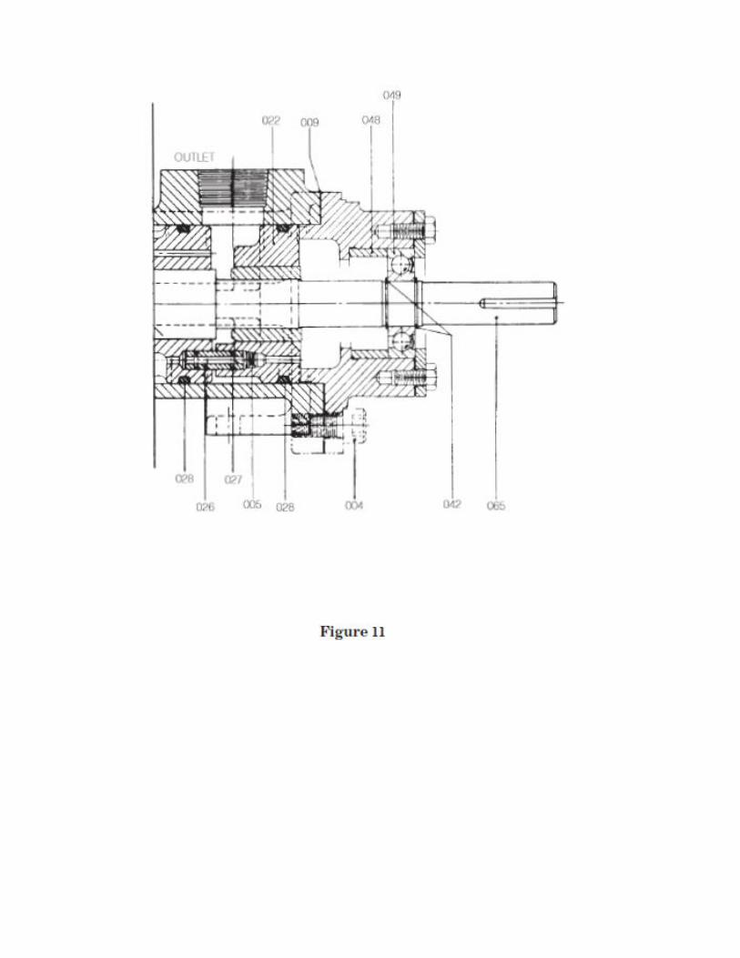
NOTE: Refer to Figure 2 for Mechanical Seal Types for proper disassembly. (Figures 3, 7, 8, 9) Remove mechanical seal rotating assembly from power rotor (044 or 063). NOTE: Refer to Figure 2 for Mechanical Seal Types for proper disassembly. (Figures 7, 8, 9) Remove sleeve (038 or 037) from power rotor (044 or 063). Assembly Procedures (Figures 3, 7, 8, 9 and 11) NOTE: Prior to pump assembly, all parts should be cleaned and inspected for nicks and burrs.
Replace all worn or damaged parts. Imo Pump Division recommends automatic replacement of O-rings (027, 028 and 038), gaskets (009), Dyna seal (007), ball bearing (049 or 015) and mechanical seal (025) when these parts are disturbed from their previously installed position. Refer to pump assembly drawings (Figures 3, 7, 8, 9), and List of Material (Table 4), during assembly. Coat all parts with light lubricating oil to assist in assembly. Assembly procedures for all A3D pumps equipped with mechanical seals are identical except when specifically noted.
WARNING
When inspecting/servicing shaft seal and/or bearing, power rotor can be removed as a subassembly with these components installed. Remove four (4) bearing retainer plate bolts and retainer plate, and then remove power rotor sub-assembly. If for any reason pump is disassembled further than this, it is possible idler rotor balance piston housings may fall off. These idler rotor balance piston housings MUST be properly in place at reassembly. If idler rotor balance piston housings are not properly installed on idler rotors, pump WILL experience catastrophic failure.
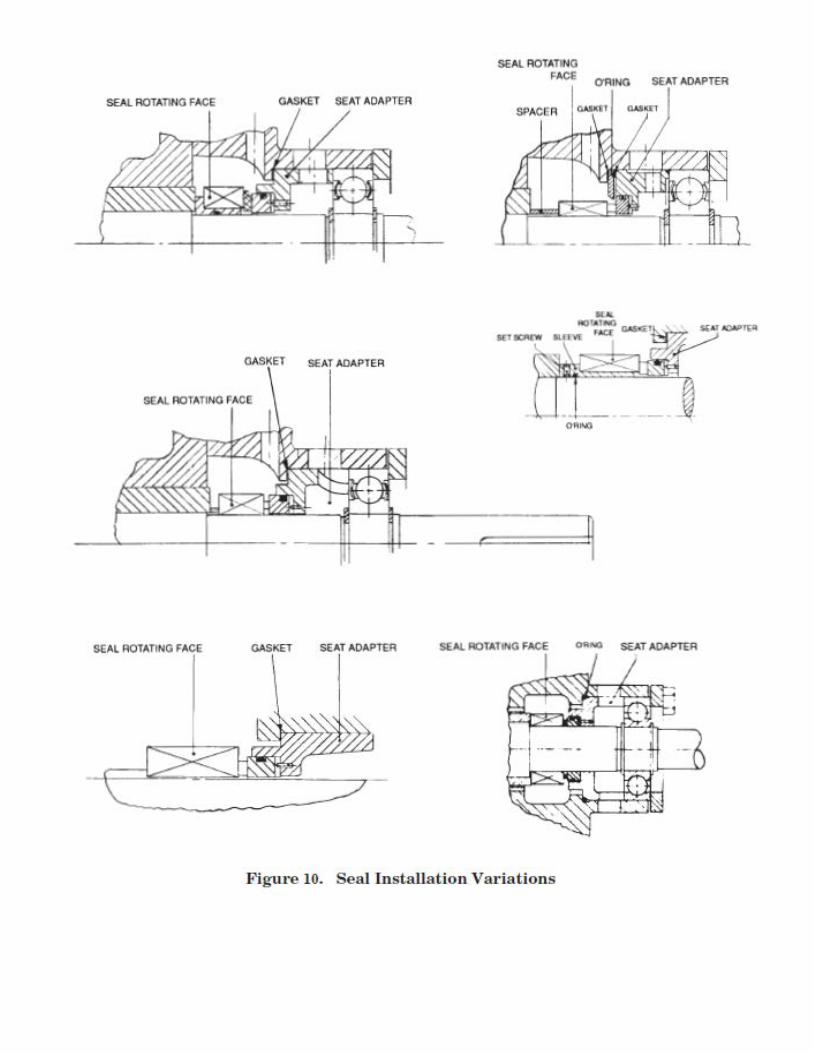
Figures 3, 7, 8, 9 are basic pump assembly figures. For variations that may apply to your pump, see
Figure 10 for seal installation variations. 1. Install O-ring (028) in groove of rotor housing (024). (Figures 3, 7, 8, 9 and 11) Install O-rings (027) on
oil balance tube (026), and install oil balance tube (026) in suction end of rotor housing (024). 2. (Figures 3, 7, 8 and 11) Install O-rings (027 or 038) on oil balance tube (026 or 036), and install oil
balance tube (026 or 036) in discharge end of rotor housing (024).
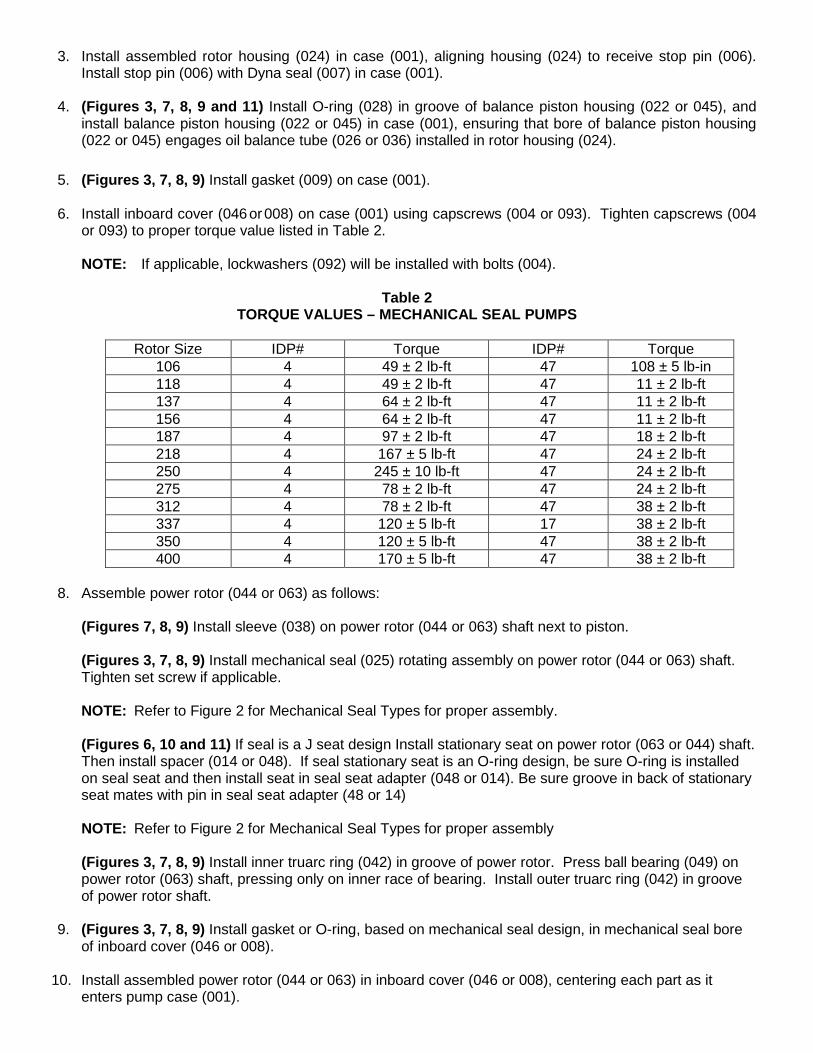
3. Install assembled rotor housing (024) in case (001), aligning housing (024) to receive stop pin (006). Install stop pin (006) with Dyna seal (007) in case (001).
4. (Figures 3, 7, 8, 9 and 11) Install O-ring (028) in groove of balance piston housing (022 or 045), and
install balance piston housing (022 or 045) in case (001), ensuring that bore of balance piston housing (022 or 045) engages oil balance tube (026 or 036) installed in rotor housing (024).
5. (Figures 3, 7, 8, 9) Install gasket (009) on case (001). 6. Install inboard cover (046 or 008) on case (001) using capscrews (004 or 093). Tighten capscrews (004
or 093) to proper torque value listed in Table 2.
NOTE: If applicable, lockwashers (092) will be installed with bolts (004).
Table 2 TORQUE VALUES – MECHANICAL SEAL PUMPS
Rotor Size IDP# Torque IDP# Torque
106 4 49 ± 2 lb-ft 47 108 ± 5 lb-in 118 4 49 ± 2 lb-ft 47 11 ± 2 lb-ft 137 4 64 ± 2 lb-ft 47 11 ± 2 lb-ft 156 4 64 ± 2 lb-ft 47 11 ± 2 lb-ft 187 4 97 ± 2 lb-ft 47 18 ± 2 lb-ft 218 4 167 ± 5 lb-ft 47 24 ± 2 lb-ft 250 4 245 ± 10 lb-ft 47 24 ± 2 lb-ft 275 4 78 ± 2 lb-ft 47 24 ± 2 lb-ft 312 4 78 ± 2 lb-ft 47 38 ± 2 lb-ft 337 4 120 ± 5 lb-ft 17 38 ± 2 lb-ft 350 4 120 ± 5 lb-ft 47 38 ± 2 lb-ft 400 4 170 ± 5 lb-ft 47 38 ± 2 lb-ft
8. Assemble power rotor (044 or 063) as follows: (Figures 7, 8, 9) Install sleeve (038) on power rotor (044 or 063) shaft next to piston. (Figures 3, 7, 8, 9) Install mechanical seal (025) rotating assembly on power rotor (044 or 063) shaft. Tighten set screw if applicable.
NOTE: Refer to Figure 2 for Mechanical Seal Types for proper assembly.
(Figures 6, 10 and 11) If seal is a J seat design Install stationary seat on power rotor (063 or 044) shaft.
Then install spacer (014 or 048). If seal stationary seat is an O-ring design, be sure O-ring is installed on seal seat and then install seat in seal seat adapter (048 or 014). Be sure groove in back of stationary seat mates with pin in seal seat adapter (48 or 14)
NOTE: Refer to Figure 2 for Mechanical Seal Types for proper assembly
(Figures 3, 7, 8, 9) Install inner truarc ring (042) in groove of power rotor. Press ball bearing (049) on
power rotor (063) shaft, pressing only on inner race of bearing. Install outer truarc ring (042) in groove of power rotor shaft.
9. (Figures 3, 7, 8, 9) Install gasket or O-ring, based on mechanical seal design, in mechanical seal bore
of inboard cover (046 or 008). 10. Install assembled power rotor (044 or 063) in inboard cover (046 or 008), centering each part as it
enters pump case (001).
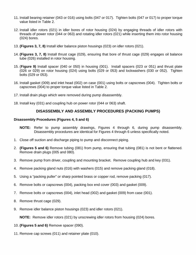
11. Install bearing retainer (043 or 016) using bolts (047 or 017). Tighten bolts (047 or 017) to proper torque
value listed in Table 2. 12. Install idler rotors (021) in idler bores of rotor housing (024) by engaging threads of idler rotors with
threads of power rotor (044 or 063) and rotating idler rotors (021) while inserting them into rotor housing (024) bores.
13. (Figures 3, 7, 8) Install idler balance piston housings (023) on idler rotors (021). 14. (Figures 3, 7, 8) Install thrust cage (029), ensuring that bore of thrust cage (029) engages oil balance
tube (026) installed in rotor housing. 15. (Figure 9) Install spacer (040 or 050) in housing (001). Install spacers (023 or 051) and thrust plate
(026 or 029) on rotor housing (024) using bolts (029 or 053) and lockwashers (030 or 052). Tighten bolts (029 or 053).
16. Install gasket (009) and inlet head (002) on case (001) using bolts or capscrews (004). Tighten bolts or
capscrews (004) to proper torque value listed in Table 2. 17. Install drain plugs which were removed during pump disassembly. 18. Install key (031) and coupling hub on power rotor (044 or 063) shaft.
DISASSEMBLY AND ASSEMBLY PROCEDURES (PACKING PUMPS)
Disassembly Procedures (Figures 4, 5 and 6)
NOTE: Refer to pump assembly drawings, Figures 4 through 6, during pump disassembly. Disassembly procedures are identical for Figures 4 through 6 unless specifically noted.
1. Close off suction and discharge piping to pump and disconnect piping. 2. (Figures 5 and 6) Remove tubing (081) from pump, ensuring that tubing (081) is not bent or flattened.
Remove drain plugs (005 and 080). 3. Remove pump from driver, coupling and mounting bracket. Remove coupling hub and key (031). 4. Remove packing gland nuts (016) with washers (015) and remove packing gland (018). 5. Using a “packing puller” or sharp pointed brass or copper rod, remove packing (017). 6. Remove bolts or capscrews (004), packing box end cover (003) and gasket (009). 7. Remove bolts or capscrews (004), inlet head (002) and gasket (009) from case (001). 8. Remove thrust cage (029). 9. Remove idler balance piston housings (023) and idler rotors (021).
NOTE: Remove idler rotors (021) by unscrewing idler rotors from housing (024) bores. 10. (Figures 5 and 6) Remove spacer (090). 11. Remove cap screws (011) and retainer plate (010).
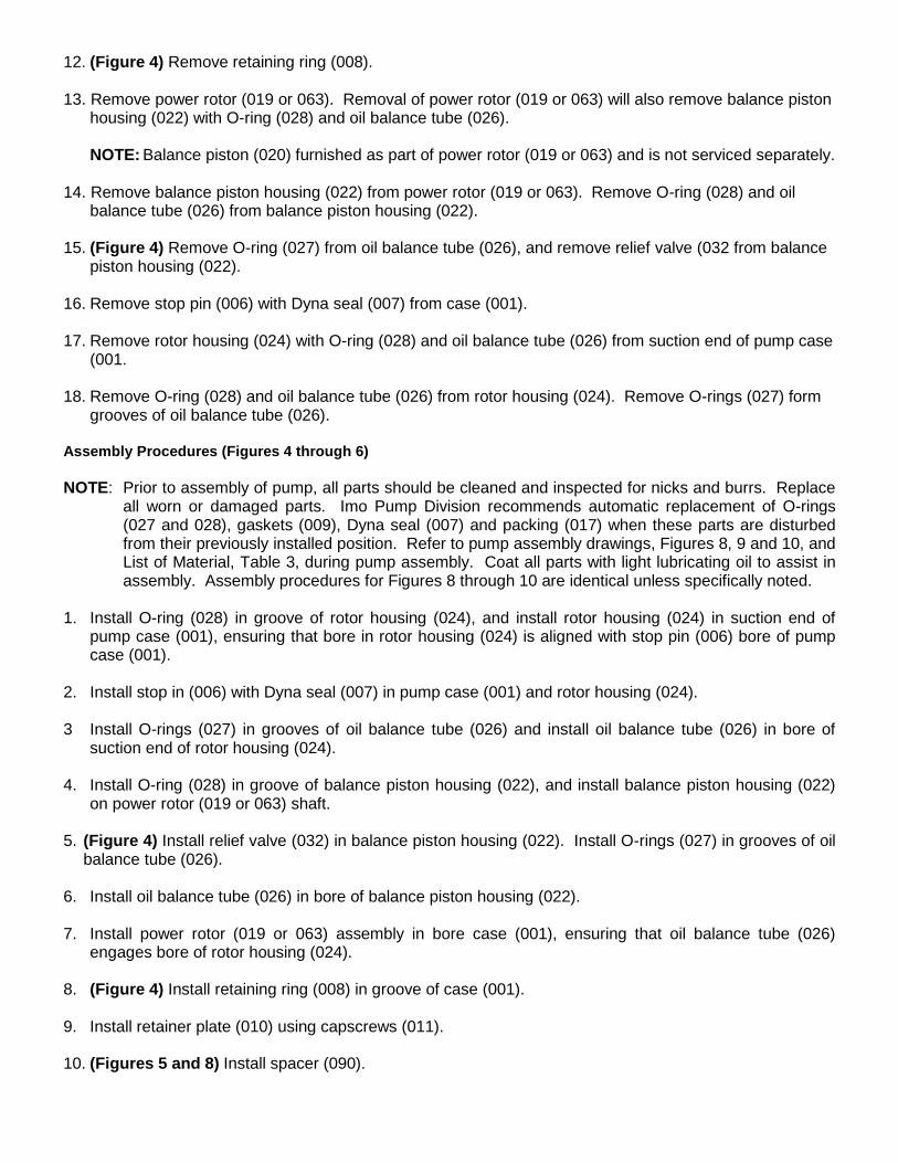
12. (Figure 4) Remove retaining ring (008). 13. Remove power rotor (019 or 063). Removal of power rotor (019 or 063) will also remove balance piston
housing (022) with O-ring (028) and oil balance tube (026). NOTE: Balance piston (020) furnished as part of power rotor (019 or 063) and is not serviced separately.
14. Remove balance piston housing (022) from power rotor (019 or 063). Remove O-ring (028) and oil
balance tube (026) from balance piston housing (022). 15. (Figure 4) Remove O-ring (027) from oil balance tube (026), and remove relief valve (032 from balance
piston housing (022). 16. Remove stop pin (006) with Dyna seal (007) from case (001). 17. Remove rotor housing (024) with O-ring (028) and oil balance tube (026) from suction end of pump case
(001. 18. Remove O-ring (028) and oil balance tube (026) from rotor housing (024). Remove O-rings (027) form
grooves of oil balance tube (026). Assembly Procedures (Figures 4 through 6) NOTE: Prior to assembly of pump, all parts should be cleaned and inspected for nicks and burrs. Replace
all worn or damaged parts. Imo Pump Division recommends automatic replacement of O-rings (027 and 028), gaskets (009), Dyna seal (007) and packing (017) when these parts are disturbed from their previously installed position. Refer to pump assembly drawings, Figures 8, 9 and 10, and List of Material, Table 3, during pump assembly. Coat all parts with light lubricating oil to assist in assembly. Assembly procedures for Figures 8 through 10 are identical unless specifically noted.
1. Install O-ring (028) in groove of rotor housing (024), and install rotor housing (024) in suction end of
pump case (001), ensuring that bore in rotor housing (024) is aligned with stop pin (006) bore of pump case (001).
2. Install stop in (006) with Dyna seal (007) in pump case (001) and rotor housing (024). 3 Install O-rings (027) in grooves of oil balance tube (026) and install oil balance tube (026) in bore of
suction end of rotor housing (024). 4. Install O-ring (028) in groove of balance piston housing (022), and install balance piston housing (022)
on power rotor (019 or 063) shaft. 5. (Figure 4) Install relief valve (032) in balance piston housing (022). Install O-rings (027) in grooves of oil
balance tube (026). 6. Install oil balance tube (026) in bore of balance piston housing (022). 7. Install power rotor (019 or 063) assembly in bore case (001), ensuring that oil balance tube (026)
engages bore of rotor housing (024). 8. (Figure 4) Install retaining ring (008) in groove of case (001). 9. Install retainer plate (010) using capscrews (011). 10. (Figures 5 and 8) Install spacer (090).
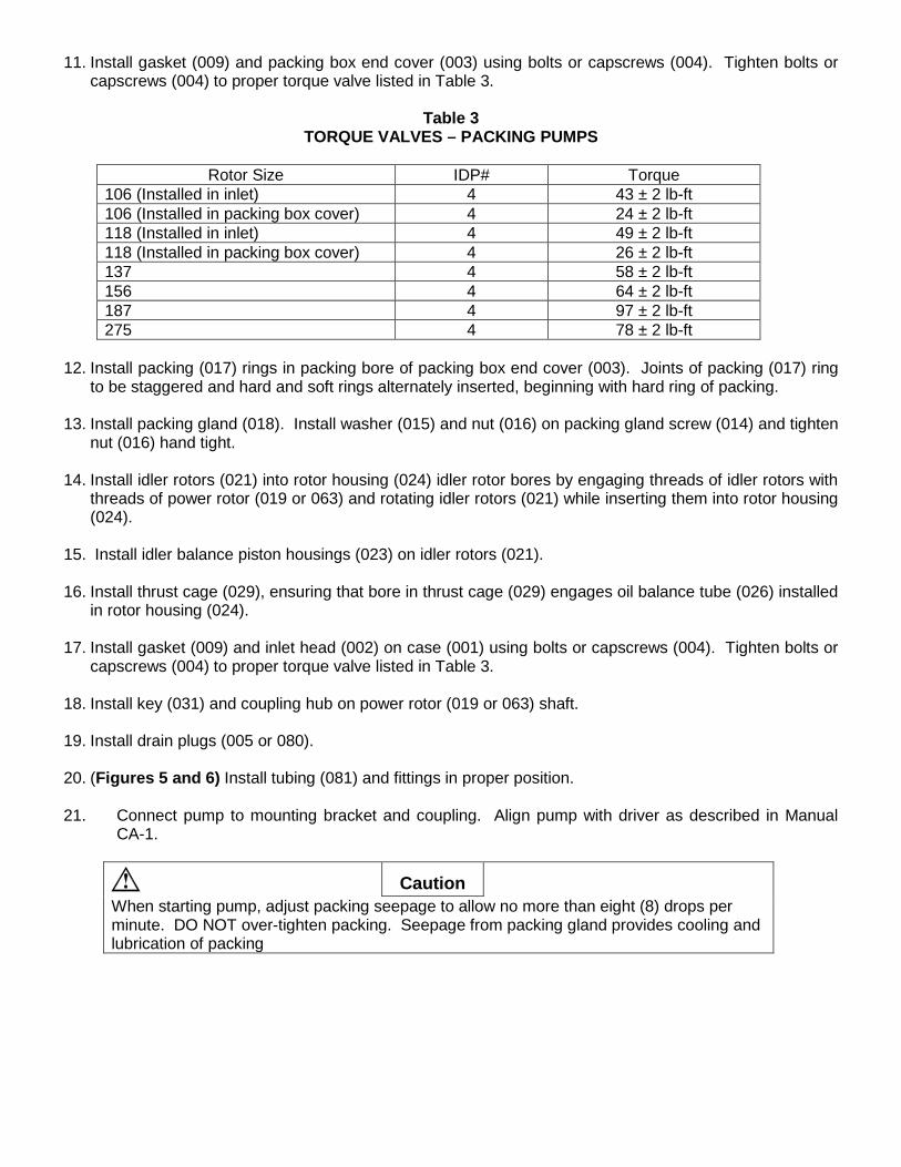
11. Install gasket (009) and packing box end cover (003) using bolts or capscrews (004). Tighten bolts or capscrews (004) to proper torque valve listed in Table 3.
Table 3
TORQUE VALVES – PACKING PUMPS
Rotor Size IDP# Torque 106 (Installed in inlet) 4 43 ± 2 lb-ft 106 (Installed in packing box cover) 4 24 ± 2 lb-ft 118 (Installed in inlet) 4 49 ± 2 lb-ft 118 (Installed in packing box cover) 4 26 ± 2 lb-ft 137 4 58 ± 2 lb-ft 156 4 64 ± 2 lb-ft 187 4 97 ± 2 lb-ft 275 4 78 ± 2 lb-ft
12. Install packing (017) rings in packing bore of packing box end cover (003). Joints of packing (017) ring
to be staggered and hard and soft rings alternately inserted, beginning with hard ring of packing. 13. Install packing gland (018). Install washer (015) and nut (016) on packing gland screw (014) and tighten
nut (016) hand tight. 14. Install idler rotors (021) into rotor housing (024) idler rotor bores by engaging threads of idler rotors with
threads of power rotor (019 or 063) and rotating idler rotors (021) while inserting them into rotor housing (024).
15. Install idler balance piston housings (023) on idler rotors (021). 16. Install thrust cage (029), ensuring that bore in thrust cage (029) engages oil balance tube (026) installed
in rotor housing (024). 17. Install gasket (009) and inlet head (002) on case (001) using bolts or capscrews (004). Tighten bolts or
capscrews (004) to proper torque valve listed in Table 3. 18. Install key (031) and coupling hub on power rotor (019 or 063) shaft. 19. Install drain plugs (005 or 080). 20. (Figures 5 and 6) Install tubing (081) and fittings in proper position. 21. Connect pump to mounting bracket and coupling. Align pump with driver as described in Manual
CA-1.
Caution
When starting pump, adjust packing seepage to allow no more than eight (8) drops per minute. DO NOT over-tighten packing. Seepage from packing gland provides cooling and lubrication of packing
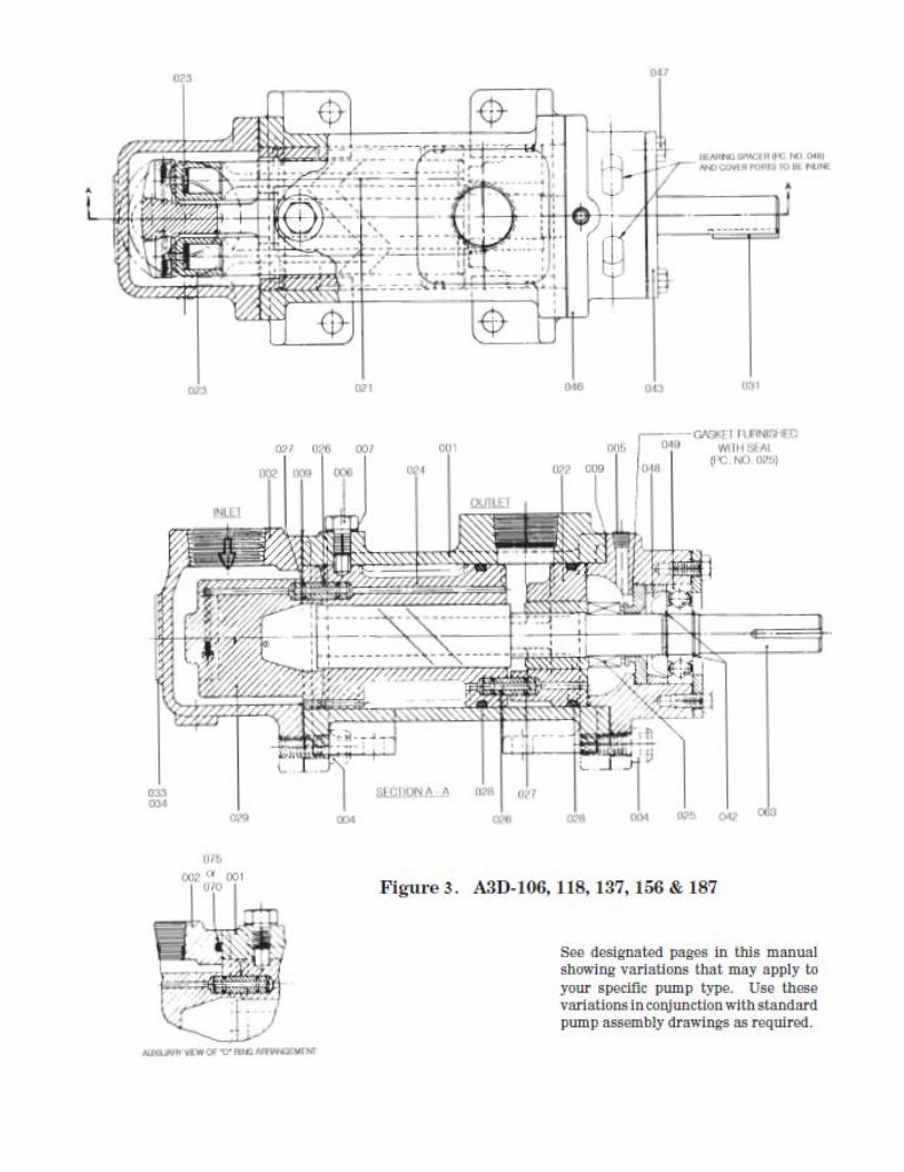
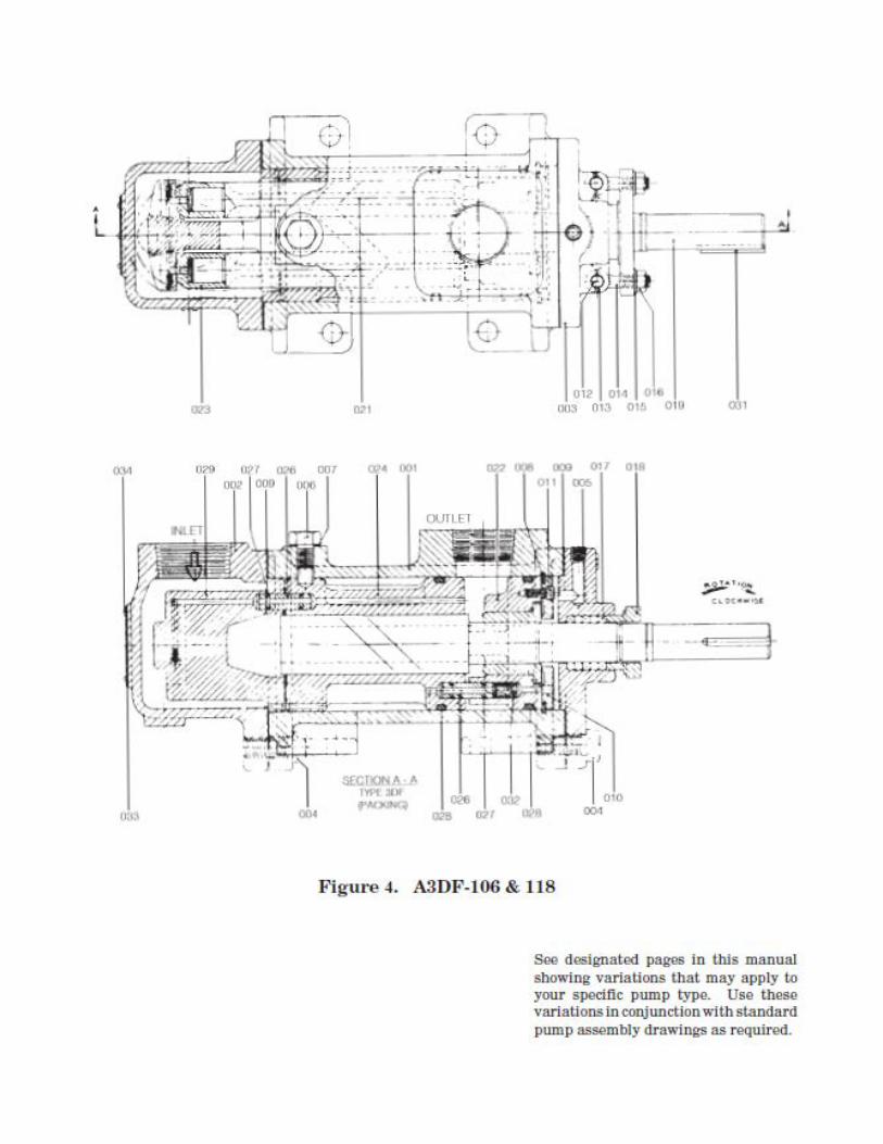
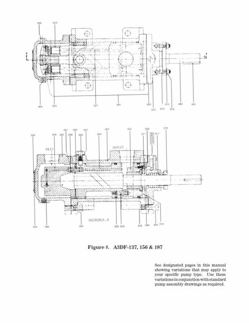
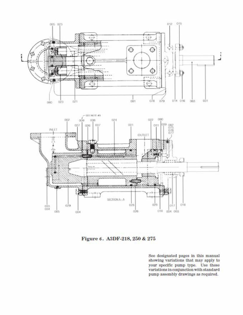
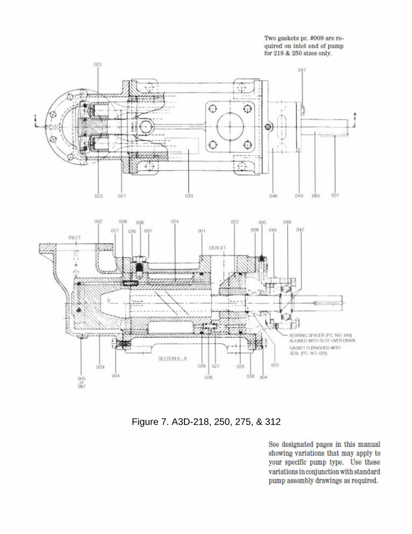
Figure 7. A3D-218, 250, 275, & 312
Colfax Fluid Handling 1710 Airport Road PO Box 5020 Monroe, NC USA 28111.5020
Tel: 1+ (704)289-6511 Email: [email protected] Web: www.imo-pump.com
© 2012 Colfax Fluid Handling all rights reserved.