instruction manual - hobbicomanuals.hobbico.com/gpm/gpma1117-manual-v1_1.pdfand assemble it as shown...
TRANSCRIPT

WARRANTYGreat Planes® Model Manufacturing Co. guarantees this kit to be free from defects in both material and workmanship at the date ofpurchase. This warranty does not cover any component parts damaged by use or modification. In no case shall Great Planes’ liabilityexceed the original cost of the purchased kit. Further, Great Planes reserves the right to change or modify this warranty without notice.
In that Great Planes has no control over the final assembly or material used for final assembly, no liability shall be assumed noraccepted for any damage resulting from the use by the user of the final user-assembled product. By the act of using the user-assembledproduct, the user accepts all resulting liability.
If the buyer is not prepared to accept the liability associated with the use of this product, the buyer is advised to return thiskit immediately in new and unused condition to the place of purchase.
To make a warranty claim send the defective part or item to Hobby Services at the address below:
Hobby Services3002 N. Apollo Dr., Suite 1Champaign, IL 61822 USA
Include a letter stating your name, return shipping address, as much contact information as possible (daytime telephone number, faxnumber, e-mail address), a detailed description of the problem and a photocopy of the purchase receipt. Upon receipt of the packagethe problem will be evaluated as quickly as possible.
READ THROUGH THIS MANUAL BEFORE STARTINGCONSTRUCTION. IT CONTAINS IMPORTANT WARNINGSAND INSTRUCTIONS CONCERNING THE ASSEMBLYAND USE OF THIS MODEL.
GPMZ0183 for GPMA1117 V1.1Entire Contents © Copyright 2006
Champaign, Illinois(217) 398-8970, Ext 5
INSTRUCTION MANUAL
Wingspan: 31 in [780 mm] Wing Area: 420 sq in [27dm2] Weight: 10 – 12 oz [285 – 340g] Wing Loading: 3.9 oz/sq ft [10 – 12g/dm2] Length: 34 in [850 mm] Radio: 4-channel w/3 micro servos and 8-Amp Brushless ESCPower System: Direct-drive RimFire™ Brushless motor (not included)
By Great Planes

2
INTRODUCTION ...............................................................2SAFETY PRECAUTIONS..................................................2LITHIUM BATTERY HANDLING & USAGE .....................3DECISIONS YOU MUST MAKE ........................................3
Motor ...........................................................................3Transmitter...................................................................3Servos .........................................................................3Receiver ......................................................................4Battery .........................................................................4Speed Control .............................................................4Charger .......................................................................4Battery Charging Leads ..............................................4Propeller Selection ......................................................4Glue.............................................................................4
ADDITIONAL ITEMS REQUIRED.....................................4Adhesives & Building Supplies....................................4
ORDERING REPLACEMENT PARTS ..............................5COMMON ABBREVIATIONS............................................5METRIC CONVERSIONS .................................................5KIT INSPECTION ..............................................................6KIT CONTENTS ................................................................6BUILDING INSTRUCTIONS..............................................7
Assemble the Horizontal Tail .......................................7Assemble the Fuselage...............................................8Finish the Fuselage...................................................10Assemble the Wing....................................................11Connect the Rod Struts.............................................12Finish the Wings........................................................13Assemble the Landing Gear......................................14Install the Servos.......................................................15Install the Motor System............................................16
GET THE MODEL READY TO FLY .................................17Check the Control Directions ....................................17Set the Control Throws..............................................18Balance the Model (C.G.)..........................................18Balance the Model Laterally......................................19
PREFLIGHT.....................................................................19Identify Your Model ....................................................19Charge the Batteries .................................................19Balance the Propellers ..............................................19Range Check.............................................................19
MOTOR SAFETY PRECAUTIONS .................................19AMA SAFETY CODE (excerpts)....................................20
General......................................................................20Radio Control ............................................................20
CHECK LIST ...................................................................20FLYING ............................................................................20
Hand Launch .............................................................20Rise-Off-Ground (ROG) Takeoffs ..............................21Flight..........................................................................21Landing......................................................................21
ANGLE TEMPLATES ......................................................23
The ElectriFly™ by Great Planes FlatOuts R/C Universe Bipeis an excellent way to enjoy 3D aerobatics without the costand headaches of giant-scale gasoline-powered models.Four to six hours on the workbench, and your R/C UniverseBipe will be ready to tackle torque rolls, walls, harriers, high-alpha rolling circles and more! An excellent indoor or calm-day outdoor performer, this airplane is a virtually unlimited3D aerobat, but flying it involves only connecting the battery,throttling up, and letting go!
Take care to build straight and true. Misaligned parts will hurtthe airplane’s ability to perform the extreme aerobatics it isdesigned for.
For the latest technical updates or manual corrections to theFlatOuts R/C Universe Bipe, visit the Great Planes web siteat www.greatplanes.com. Open the “Airplanes” link, andthen select the FlatOuts R/C Universe Bipe ARF. If there isnew technical information or changes to this model, a “technotice” box will appear in the upper left corner of the page.
Attention: The product you have purchased ispowered by a rechargeable battery. At the endof its useful life, under various state and locallaws, it may be illegal to dispose of this batteryinto the municipal waste system. Check with
your local solid waste officials for details in your area forrecycling options or proper disposal.
This product contains a chemical known to the state ofCalifornia to cause cancer and birth defects or otherreproductive harm.
1. Even though the FlatOuts R/C Universe Bipe is small,lightweight and flies slowly, if it is not assembled andoperated correctly it could possibly cause injury to yourselfor spectators and damage property.
PROTECT YOUR MODEL, YOURSELF& OTHERS...FOLLOW THESE
IMPORTANT SAFETY PRECAUTIONS
CAUTION: Be aware that the FlatOuts R/C Universe Bipe isoperated on the same frequency band as larger, “regular”R/C models. If flying your R/C Universe Bipe within five milesof an R/C site, there is a real possibility that you could beoperating your model on the same frequency (channel) asanother R/C pilot. If this happens a crash will result–with theperson flying the more expensive model suffering thegreater loss (and having greater potential for propertydamage or injury).The best thing to do is to join an R/C cluband fly at the site where frequency control measures will bein effect. If you insist on flying elsewhere, always be awareof your proximity to R/C flying sites.
INTRODUCTIONTABLE OF CONTENTS

2. Build the plane according to the instructions. Do notalter or modify the model, as doing so may result in anunsafe or unflyable model.
3. Use an R/C radio system and components that are in first-class condition. The FlatOuts R/C Universe Bipe requiresspecialized radio gear. Refer to “DECISIONS YOU MUSTMAKE” to get an accurate description of the specializedgear required.
4. You must properly install all R/C and other components sothat the model operates correctly on the ground and in the air.
5. You must test the operation of the model before everyflight to insure that all equipment is operating, and that themodel has remained structurally sound. Be sure to checkconnectors often and replace them if they show signs ofwear or fatigue.
Remember: Take your time and follow directions to endup with a well-built model that is straight and true.
If you’re not already an AMA (Academy of ModelAeronautics) member, we highly recommend that you join.In addition to providing liability protection while operatingunder the AMA Safety Code, the AMA is the governing bodyof model aeronautics in the United States and fights for yourrights as member of the modeling community.You must alsobe an AMA member to fly at R/C clubs chartered by theAMA–most of which are. Contact the AMA at the address ortoll-free phone number below.
WARNING!! Failure to follow all instructions could causepermanent damage to the battery and its surroundings, andcause bodily harm!
• ONLY use a LiPo approved charger. NEVER use aNiCd/NiMH peak charger!
• NEVER charge in excess of 4.20V per cell.• ONLY charge through the “charge” lead. NEVER charge
through the “discharge” lead.• NEVER charge at currents greater than 1C.• ALWAYS set charger’s output volts to match battery volts.• ALWAYS charge in a fireproof location.• NEVER trickle charge.• NEVER allow the battery temperature to exceed
50°F (65°C).• NEVER disassemble or modify pack wiring in any way or
puncture cells.• NEVER discharge below 2.5V per cell.• NEVER place on combustible materials or leave
unattended during charge or discharge.• ALWAYS KEEP OUT OF REACH OF CHILDREN.
In the hands of a capable pilot, the FlatOuts R/C UniverseBipe is an impressive 3D performer. But for the R/C UniverseBipe to perform to its full potential, it must be properlyequipped with all the right gear (servos, batteries, receiver,speed control). There may be more than one type and brandof radio equipment that can be used, but based on extensivetesting, following is the equipment we recommend so youcan get the most performance out of your R/C Universe Bipeand assemble it as shown in this instruction manual.
The FlatOuts R/C Universe Bipe performs extremely wellwith the Great Planes RimFire™ 22M-1000 Brushless Motor(GPMG4500) and it is the recommended motor for thisairplane. This manual covers the installation of the RimFiremotor and the plywood firewall included is designedspecifically for use with the RimFire. Other motors can beused, however modification may be required for installation.
With a standard, four-channel radio, the FlatOuts R/CUniverse Bipe is capable of all the basic 3D maneuvers.However, some advanced pilots who are already familiarwith handling “flat foamies” may prefer to fly this FlatOutswith a computer radio capable of endpoint adjustments (forfine-tuning control throws), exponentials (for “softening” thethrows near the center of the travel), and various mixingfunctions (such as rudder-to-elevator mixing for extendedknife-edge flight).
The FlatOuts R/C Universe Bipe requires three micro servoswith a maximum weight of 9g [.3 oz] each and a minimumtorque rating of 15 oz-in. Futaba® S3108 servos
Servos
Transmitter
Motor
DECISIONS YOU MUST MAKE
LITHIUM BATTERY HANDLING & USAGE
Academy of Model Aeronautics5151 East Memorial Drive
Muncie, IN 47302Tele: (800) 435-9262Fax (765) 741-0057
Or via the Internet at:http://www.modelaircraft.org
Note: We, as the kit manufacturer, provide you with a topquality kit and great instructions, but ultimately the qualityand flyability of your finished model depends on how youbuild it; therefore, we cannot in any way guarantee theperformance of your completed model, and norepresentations are expressed or implied as to theperformance or safety of your completed model.
3

(FUTM0042) are ideal because they meet the torque andweight requirements. Although there may be other servosthat will physically fit in the model, those outside therecommended weight and torque specifications willadversely affect flight performance and are notrecommended. Note: During assembly when it’s time tomount the servos, you will be instructed to glue them in. Donot be alarmed as this is a common practice with this typeof lightweight, high-performance model. Should servoremoval ever be necessary for repair, replacement ortransfer to another model, this can be done by prying themout with a hobby knife or a small screwdriver.
A light, four-channel receiver is recommended and must becompatible with whatever servos will be used (not all servosare compatible with all receivers–even servos and receiverswithin the same brand). The Futaba R-114F Micro receiver isrecommended and is compatible with the S3108 servosrecommended. Note: Futaba receivers are sold on high andlow bands and come without crystals. Following are the ordernumbers for the R-114F receiver and compatible crystals:
Low Band High Band(Channels 11-35) (Channels 36-60)
R124F Receiver FUTL0438 FUTL0439Crystal FUTL62** FUTL63****Replace the “**” in the order number for the crystals withthe preferred channel number. For example, if you want to flyon channel 33, order a low band receiver and crystalnumber FUTL6233.
The FlatOuts R/C Universe Bipe requires a 3-cell (11.1V),350–700mAh lithium-polymer (LiPo) battery capable ofproviding 7A continuous discharge current. The ElectriFly 3-cell, 3-Series 640mAh battery pack is recommended(GPMP0805). Note: The ElectriFly 720mAh battery is notrecommended for this model as it is not capable ofdelivering the current required by this system. For optimumperformance, battery weight should not exceed 54g [2 oz.].
An electronic speed control capable of handling a minimumof 8A continuous current is required. Additionally, the speedcontrol should be as light as possible. The ElectriFly BL-8Micro Brushless ESC w/BEC (GPMM2070) or the ElectriflySilver Series 8A Brushless ESC w/BEC (GPMM1800) aresuitable. NEVER use speed controllers intended forbrushed motors on brushless motors.
A charger capable of charging 3-cell (11.1V) LiPo batteriessuch as the ElectriFly PolyCharge 1 to 3-cell LiPo charger(GPMM3010) must be used. If using another charger, itmust be a LiPo charger or have a LiPo charge mode. Nevercharge LiPo batteries with chargers not intended for LiPobatteries or chargers on NiMH or NiCd settings.Overcharging or explosion may result. In addition to thePolyCharge, the ElectriFly Triton™ (GPMM3150) or Accu-Cycle Elite™ (HCAP0280) are also suitable chargers.
Many chargers (including the Triton and Accu-Cycle Elitelisted above) do not include charging leads, but rather havebanana jacks to plug the leads into. If this is the case withyour charger, you will need to purchase a charge lead tomatch your battery. For the recommended 640mAh pack,the correct lead is GPMM3105.
The Great Planes 9x3.5S (GPMQ6625) propeller offers verygood performance with the Great Planes RimFire motor system.A Great Planes 10x3.5 (GPMQ6655) propeller will also offergood performance.
Though there may be a few different types of adhesives thatthe FlatOuts R/C Universe Bipe could be assembled with, wehave had the best success with and exclusively recommend,foam-safe CA such as Great Planes 1 oz. thick, foam-safe CA(GPMR6072). Thin, foam-safe CA such as Hot Stuff UFO thinCA (HOTR1040) is also used in the construction of this model.Regular CA is not recommended as it will aggressively attackthe foam used in this model. In addition to being foam-compatible, foam-safe CA is also suitable for gluing together allof the rest of the materials (balsa, carbon) included in this kit.No other adhesive is required to build the FlatOuts R/CUniverse Bipe.
In addition to common household tools and hobby tools, thisis the “short list” of the most important items required to buildthe FlatOuts R/C Universe Bipe:
❏ Great Planes Aerosol Activator (GPMR6034)❏ Hobbico® CA Applicator tips (HCAR3780)❏ Hobby knife with #11 blade (HCAR0100)
Adhesives & Building Supplies
ADDITIONAL ITEMS REQUIRED
Glue
Propeller Selection
Battery Charging Leads
Charger
Speed Control
Battery
Receiver
4

❏ #11 blades (5-pack – HCAR0211)❏ 1-meter metric ruler (for identifying tubes and rods)❏ 5-1/2" [140 mm] Easy-Touch™ bar sander (GPMR6169)
with 220-grit sandpaper (GPMR6185)❏ Drill bits: 1/16" [1.5 mm], 3/32" [2.5 mm] ❏ Double-sided foam tape (GPMQ4400)❏ Stick-on weight (GPMQ4485)❏ Great Planes Plan Protector™ (GPMR6167) or wax paper
Replacement parts for the Great Planes FlatOuts R/CUniverse Bipe ARF are available using the order numbers inthe Replacement Parts List that follows. The fastest, mosteconomical service can be provided by your hobby dealer ormail-order company.
To locate a hobby dealer, visit the Hobbico web site atwww.hobbico.com. Choose “Where to Buy” at the bottom ofthe menu on the left side of the page. Follow the instructionsprovided on the page to locate a U.S., Canadian or Internationaldealer. If a hobby shop is not available, replacement parts may alsobe ordered from Tower Hobbies® at www.towerhobbies.com,or by calling toll free (800) 637-6050.
Parts may also be ordered directly from Hobby Services bycalling (217) 398-0007, or via facsimile at (217) 398-7721,but full retail prices and shipping and handling charges willapply. Illinois and Nevada residents will also be chargedsales tax. If ordering via fax, include a Visa® or MasterCard®
number and expiration date for payment.
Mail parts orders and payments by personal check to:
Hobby Services3002 N. Apollo Drive, Suite 1
Champaign, IL 61822
Be certain to specify the order number exactly as listed inthe Replacement Parts List. Payment by credit card orpersonal check only; no C.O.D.
If additional assistance is required for any reason contact ProductSupport by e-mail at [email protected], orby telephone at (217) 398-8970.
Replacement Parts List
Order Number Description How to PurchaseMissing pieces Contact Product SupportInstruction manual Contact Product SupportFull-size plans Not available
GPMQ6625 9x3.5S Propeller Contact Hobby SupplierGPMQ4618 Prop Saver O-ring Contact Hobby SupplierGPMQ4620 Prop Saver Contact Hobby Supplier
Fuse = FuselageStab = Horizontal Stabilizer
Fin = Vertical FinLE = Leading EdgeTE = Trailing EdgeLG = Landing GearPly = Plywood
" = Inchesmm = Millimeters
SHCS = Socket Head Cap Screw
1" = 25.4 mm (conversion factor)
METRIC CONVERSIONS
COMMON ABBREVIATIONS
ORDERING REPLACEMENT PARTS
5
1/64" = .4 mm1/32" = .8 mm1/16" = 1.6 mm3/32" = 2.4 mm1/8" = 3.2 mm
5/32" = 4.0 mm3/16" = 4.8 mm1/4" = 6.4 mm3/8" = 9.5 mm1/2" = 12.7 mm5/8" = 15.9 mm
3/4" = 19.0 mm1" = 25.4 mm2" = 50.8 mm3" = 76.2 mm6" = 152.4 mm
12" = 304.8 mm18" = 457.2 mm21" = 533.4 mm24" = 609.6 mm30" = 762.0 mm36" = 914.4 mm

6
Before starting to build, take an inventory of this kit to make sure it is complete, and inspect the parts to make sure theyare of acceptable quality. If any parts are missing or are not of acceptable quality, or if you need assistance with assembly,contact Product Support. When reporting defective or missing parts, use the part names exactly as they are written inthe Kit Contents list.
Great Planes Product Support:3002 N. Apollo Drive, Suite 1
Champaign, IL 61822Telephone: (217) 398-8970, ext. 5
Fax: (217) 398-7721E-mail: [email protected]
KIT INSPECTION
Plastic Tree PartsA1 Z-Bend Clevis (10)A2 Offset Z-Bend Clevis (4)B1 Stand-Alone Control Horn (5)B2 Stand-Alone Control Horn Retainer (5)C1 Clip Hinge Control Horn (5)C2 Clip Hinge (26)C3 Hinge Retainer Ring (10)C4 Aileron Link Horn (4)D1 Axle Support (2)D2 Rod Support (12)D4 Tailwheel Bracket (1)D5 Tailwheel (1)D6 Wheel Collar (2)E1 Control Surface Brace (4)E2 Fuselage Joiner (3)E3 Pushrod Support (4)
F1 Wire Clip (4)F2 Aileron Servo Mounting Tray (1)F3 Fuselage Servo Mount (2)F4 Fuselage Aileron Servo Mount (1)G1 Double-Sided Offset Arm, Size B (2)G2 Double-Sided Arm, Size B (2)G3 Single-Sided Arm, Size B (4)G4 Double-Sided Arm, Size A (2)G5 Double-Sided Offset Arm, Size A (2)G6 Single-Sided Arm, Size A (4)G7 Double-Sided Arm, Size C (2)G8 Double-Sided Offset Arm, Size C (2)G9 Single-Aided Arm, Size C (4)
Carbon Rods & TubesFuselage Doubler Tube 5.5 x 295 mmElevator Joiner Tube 3 x 216 mm
Rudder Post Tube 3 x 145 mmFuselage Main Tube 3 x 684 mmLeading Edge Tube 3 x 650 mm (2)Trailing Edge Tube 3 x 370 mm (4)Landing Gear Rods 2 x 190 mm (2)Wheel Axles 2 x 17 mm (2)Rudder Pushrod 1 x 340 mmElevator Pushrod 1 x 370 mmAileron Pushrod 1 x 80 mm (2)Aileron Link Pushrod 1 x 165 mm (2)
Other PartsFirewallO-ringsTop Wing Braces 2 x 115 mm (4)Bottom Wing Braces 2 x 85 mm (2)
Kit Contents (Not Photographed)
KIT CONTENTS
Kit Contents
1. Top Wing & Ailerons2. Bottom Wing & Ailerons3. Rudder4. Plywood Firewall5. Main Wheels6. Hook and Loop Material7. Upper Vertical Fuselage Half8. Lower Vertical Fuselage Half9. Propeller10. Small Vertical Nose Doublers (2)11. Prop Saver12. Horizontal Fuselage Halves (L&R)13. Interplane Struts (L&R)14. Fuselage Braces (L&R)15. Inner Wheel Pants (L&R)16. Outer Wheel Pants (L&R)17. Horizontal Nose Doublers (4)18. Large Vertical Nose Doublers (2)19. Horizontal Stabilizer w/Elevators
1 3
7
8
9
10
2
5
46
11
12
13 14 1617
19
18
15

Please note that all of the plastic parts used when buildingthe FlatOuts R/C Universe Bipe are identified by name andpart number, for example: Z-bend clevis (A1). The partnumbers are molded next to each part on the parts trees foreasy identification.
The carbon tube diameters referenced throughout thismanual may be difficult to measure without calipers. Thedimensions provided consist of 1 mm, 2 mm, 3 mm, and 5.5mm. These four sizes can be identified by comparing all thetubes next to each other. Once the diameters aredetermined, it is advisable to group the tubes together bysize for quick reference.
❏ 1. Cut the horizontal stabilizer free from the foam sheetusing a hobby knife with a sharp #11 blade. DO NOT cut theelevator halves free at this time.
❏ 2. Without removing the elevator halves from the foamsheet, slide two hinge retainer rings (C3) onto the elevatorjoiner tube. Align the rings with the cutout in the left elevatorhalf. The ring on the right should be in line with the edge ofthe cutout and there should be a 1.5 mm [1/16"] gapbetween the two rings. Secure both rings to the tube with adrop of glue on the outside of the gap.
❏ 3. Using the Expert Tip that follows, permanently join theelevator halves by gluing in the 3 x 216 mm [1/8" x 8-1/2"]elevator joiner tube.
❏ 4. Now the elevator halves may be cut from the sheet.
❏ 5.To avoid broken clip hinges (C2) and control horns (C1)during assembly, trim them as shown before installing ontothe 3mm carbon tubes.
HOW TO GLUE THE TUBES TOTHE CONTROL SURFACES
Note: You may want to protect your work surface fromexcess glue. We recommend the use of Great Planes PlanProtector™ (GPMR6167) for this purpose.
A. Cut several 40 mm [1-1/2"] pieces of cellophane tape. Foldthe last 5 mm [1/4"] over to make a tab for easy removal.
B. Lightly coat the leading edges of the elevators withfoam-safe CA–do not use an excessive amount. Hint: ACA applicator tip is recommended to accurately controlthe bead of glue.
C. Tape the tube to the leading edge of the elevators.Weight the assembly down on a flat surface to preventwarping and allow the glue to harden without accelerator.
D. Once the glue has hardened, remove the tape.
E. Add a fillet of glue to the bottom of the joiner tubeand elevators.
Assemble the Horizontal Tail
BUILDING INSTRUCTIONS
7

❏ 6. Snap all the clip hinges to the carbon tube already gluedto the elevators. Push the hinges into the slots in the stabilizer.Make sure the hinges are centered in the stabilizer. Add a dropof oil to each hinge. Glue the hinges into the stabilizer with adrop or two of foam-safe thin CA (Hot Stuff UFO Thin Foam-Safe 1 oz, HOTR1040) where shown.
❏ 7. Enlarge the hole in the Z-bend clevis (A1) with a #59(.041") drill bit. Enlarge the hole in a clip-hinge control horn(C1) with a #38 (.101") drill bit. Insert the Z-bend clevis (A1)into the clip-hinge control horn (C1) as shown.
❏ 8. Clip the control horn onto the joiner tube aligned withthe precut slot. The control horn must extend above the topof the elevator.
❏ 9. Coat the gluing area on the control horn with thick,foam-safe CA glue and rotate it down into the precut slot.
❏ 1. Cut the upper and lower vertical fuselage halvesand the left and right horizontal fuselage halves free fromtheir foam sheets.
❏ 2. Glue the 3 x 684 mm [1/8" x 26-15/16"] fuselage tubeinto the 5.5 x 295 mm [7/32" x 11-5/8"] fuselage tubedoubler. One end should be flush. From now on, thisassembly will be referred to as the fuselage tube.
Assemble the Fuselage
8

❏ 3. Slide a fuselage joiner (E2), two fuselage servo mounts(F3, F4), (F3 and F4 are the same and are interchangeable),and another fuselage joiner onto the fuselage tube. With thetube doubler forward, the front servo mount should point up withits flat surface on the left, and the rear servo mount should pointdown with its flat surface on the right.
❏ 4.Position the servo mounts and fuselage joiners so that theyalign with the precut slots in the upper vertical fuselage half.
❏ 5. Glue the fuselage tube to the upper vertical fuselage half.
❏ 6. Glue the left and right horizontal fuselage halves to thefuselage tube. Make sure they are perpendicular to theupper vertical fuselage.
❏ 7. Glue the lower vertical fuselage half to the fuselagetube. Make sure to keep it parallel with the upper half andperpendicular to the horizontal fuselage.
❏ 8. Glue the stabilizer into position as far forward in thestabilizer slot as it will go. Be sure that the stab is centeredleft to right and is perpendicular to the fuselage.
❏ 9. Slide two hinge retainer rings (C3) onto the rudderpost tube. Test fit the tube onto the fuselage and center therings in the gap shown, leaving 1.5 mm [1/16"] betweenthem. When satisfied with the fit, glue the rings to the tubeand glue the tube to the fuselage.
9

❏ 10. Using the same technique as you did with the horizontalstabilizer, attach four clip hinges into the rudder centeringthem properly at the locations shown in the picture.
❏ 11. Install a Z-bend clevis (A1) into a clip hinge controlhorn (C1). Clip the control horn on the right side of therudder between the retainer rings. Snap the rudder onto therudder tube and glue the control horn and hinges intoposition. Be sure that the rudder moves freely.
❏ 12. Snap the tailwheel (D5) into the tailwheel bracket(D4) and slide the tailwheel bracket onto the rudder posttube. Glue this assembly to the rudder. Do not glue thetailwheel bracket to the tube.
❏ 1. Locate the horizontal and vertical nose doublersand cut them from the foam sheets. Notice that the smallervertical nose doublers look the same as the horizontaldoublers but have notches in the front.
❏ 2. Align the vertical doublers flush with the top andbottom of the fuselage and glue them into position.
❏ 3. Glue the horizontal doublers to the fuselage as you didwith the vertical doublers.
Finish the Fuselage
10

❏ 1. Cut the wings and all four ailerons free from the foamsheet. Identify the top and bottom wings.The bottom wing hasthe aileron servo bay. Locate the 3 x 650 mm [1/8" x 25-9/16"]wing leading edge tubes. Glue these tubes to both the topand bottom wings.
❏ 2. As you did with the rudder and elevators, slide twohinge retainer rings (C3) onto each of the four wing trailingedge tubes to be centered in the notches in the wing. Gluethe rings to the tubes and glue the tubes to the wings.
❏ 3. Clip the upper and lower ailerons to the trailing edgetubes with clip hinges (C2) and glue the hinges into place.
❏ 4. Slide the bottom wing into the cutout in the fuselageand center it laterally and perpendicular to the fuselage.When satisfied with the fit, glue the lower wing to thefuselage by running a bead of glue down each corner wherethe wing and fuse meet.
❏ 5. Cut two stand-alone control horns (B1) and two stand-alone control horn retainers (B2) from the parts tree.Enlarge the holes with a #38 (.101") drill bit.
❏ 6. Insert the control horns into the slots in the lowerailerons with the hole in the horn pointing down andpositioned over the hinge line. Press the control hornretainers onto the control horns and secure them with a fewdrops of glue.
Assemble the Wing
11

❏ 7. Glue the interplane struts into the lower wing.The redsides of the struts points outward. Try to glue the struts sothey are 90 degrees to the wing. However, the top wing willalign the struts straight when completed.
❏ 8. Glue the top wing to the fuselage and wing struts.
❏ 1. Locate sixteen rod supports (D2), four 2 x 115 mm[5/64" x 4-1/2"] top wing braces, two 2 x 85 mm [5/64" x
3-11/32"] bottom wing braces, and two 2 x 190 mm [5/64"x 7-1/2"] landing gear rods.
❏ 2.There are four square cutouts in the center of the fuselagebetween the wings.Each cutout receives two rod supports gluedside-by-side and facing opposite directions. It does not matterwhich rod support is in the forward position.
❏ 3. Make note how the holes in the rod supports areangled. The rod supports must be installed so that theseholes are aligned to accept the carbon rods.
❏ 4. The rectangular cutouts at the leading and trailing edgesof the wings will only receive one rod support per cutout. Installthem into the cutouts.
Before gluing any parts in the following steps, it is a goodidea to dry fit the supports and braces to be sure they arebeing installed in the correct orientation. Rather thanprovide excessive text describing the installation of eachbrace, simply refer to the picture of the completed wingbraces below for their locations on the plane.
Connect the Rod Struts
12

❏ 5. Correctly position the rod supports into the wings andfuselage (test fitting the braces into the supports as needed)and gluing them permanently when satisfied.
❏ 6. Slide the braces into their respective rod supportsbased on the completed picture above and center theirpositions. Glue the braces one end at a time to the rodsupports. “Skew” the wing assembly if necessary during thisprocess so that all the rods evenly align and the top andbottom wings are square to the fuselage.
❏ 1. Locate four Z-bend clevises (A1) and four aileron linkhorns (C4) and cut them from the parts tree.
❏ 2. Press the clevises into the aileron link horns (C4) asdone in prior steps.
❏ 3. Insert the two 1 x 165 mm [1/32" x 6-1/2"] aileronjoiner pushrods into the Z-bend clevises connecting thetop and bottom ailerons (sanding the ends of the pushrodsto a dull point will allow them to slide into the cleviseseasier). Be sure that the Z-bend clevises are on the sameside of the link horns for each set of ailerons.
❏ 4. Position the link horns into the slots at the trailingedges of all four ailerons as shown and glue them into place.Adjust the pushrods in the clevises so that the ailerons areparallel. Add a couple drops of glue to each clevis at thepushrod to secure them into place. Be careful not to glue theclevises to the link horns.
❏ 5. Glue four control surface braces (E1) onto the inside ofeach aileron 13 mm [1/2"] back from the aileron leading edges.
Finish the Wings
13

❏ 6. Cut a 45° beveled edge on the sides and tips of thefuselage braces with a sharp hobby knife. Make a shallowcut along the line shown in the picture. Do not cut all the waythrough the foam for this cut.
❏ 7. Align the colored pattern on the fuselage braces with thecolors on the fuselage and glue them into position. Thesebraces mount at a 45° angle to the fuselage, matching thebevel cuts you made in the prior step. Bend the triangle shapedtips of the braces inward to glue against the fuselage.
❏ 1. Glue the inner wheel pants to the outer wheel pants.Be sure to make one left and one right wheel pant.
❏ 2. Assemble the axle supports (D1), axles, wheels, andwheel collars (D6) to make two landing gear assemblies.Secure the wheel collar to the axle with a drop of glue, butdo not glue the axle to the axle support until later. Be surethat the wheels rotate freely.
❏ 3. Glue the wheel pants to the wheel collars. You do notneed to align the position of the axle supports at this time.
❏ 4. Slide the wheel assemblies onto the 2 x 190 mm [5/64"x 7-1/2"] landing gear rods. Rotate the assemblies so that thewheel pant bottoms are parallel with the wings and the wheelsare pointed straight ahead. When satisfied with their fit, applya few drops of glue to the axle supports at the axles and at thelanding gear rods.
Assemble the Landing Gear
14

❏ 1. Remove the stock servo arms from all three of the servos.
❏ 2. Refer to the Kit Contents section on page 5 and selectthe correct spline size for the servos you will be using. Thereare three sizes to choose from:
(G1 - G3) Futaba S3103, Airtronics 94091(G4 - G6) Hitec HS-55, Hitec HS-50, Futaba 3108M(G7 - G9) JR 241
❏ 3. Glue the rudder servo into the rear servo mount in theright side of the fuselage. The output shaft should be forward.
❏ 4. Glue the elevator servo into the front servo mount in theleft side of the fuselage. The output shaft should be forward.
❏ 5. Glue the aileron servo mounting tray (F2) over thecutout in the underside of the wing.
❏ 6. Glue the aileron servo into the tray with the output shaftfacing toward the back of the airplane.
❏ 7. Cut two small holes in the fuselage for the elevatorservo wire to pass through to the left lower quadrant. Usedouble-sided servo tape (not included) to secure thereceiver to the underside of the horizontal fuselage sectionon the left side. Be sure to position the receiver so that allthe servo wires can reach it without the use of servoextensions. Connect the servos to the receiver and power upthe radio system to center all three servos.
Install the Servos
15

❏ 8. Insert two Z-bend clevises (A1) into the outer holes of adouble-sided servo arm that fits your servo and two Z-bendclevises into the aileron control horns.Push the 1 x 80 mm [1/32"x 3-1/8"] aileron pushrods into the clevises on the controlhorns. Now attach the clevises in the servo arm onto the otherends of the pushrods. Screw the arm onto the aileron servo andadjust the depth of the pushrods in the clevises so that theailerons are in the neutral position when the servo arm is parallelto the wing leading edge. When satisfied with their fit, a fewdrops of glue on the pushrods will secure them in place.
❏ 9. Fit a Z-bend clevis into the middle hole of a single-sided servo arm that fits your servo. Slide the 1 x 340 mm[1/32" x 13-1/2"] rudder pushrod into the clevis in the servoarm and slide two pushrod supports (E3) onto the otherend of the rod.
❏ 10. Attach the other end of the rudder pushrod to theclevis in the control horn and secure the arm to the servo.Adjust the pushrod as you did with the ailerons so that therudder is neutral with the servo arm pointing straight down.Glue the pushrod to the clevises and attach the supports tothe fuselage an equal distance apart (pre-drilling a hole forthe supports with a 2.4 mm [3/32"] bit is recommended). Donot push the supports all the way through the fuselage. Gluethe supports in place.
❏ 11. Repeat the same procedure with the elevator servousing the 1 x 370 mm [1/32" x 14-5/8"] elevator pushrod.Connect the clevis to the outer hole on the servo arm.
❏ 1. If necessary, use a bar sander with 220-grit sandpaperto lightly sand the front of the fuselage even. Be careful notto change the built-in thrust angles.
❏ 2. If installing an ElectriFly RimFire™ motor, glue theincluded 3 mm [1/8"] plywood firewall to the nose so that thecenter hole is centered on the fuselage tube. Note: Ifinstalling another brand of outrunner motor, you will need tocut your own or modify the included firewall to match itsmount pattern. The motor and firewall should be mounted sothat the thrust line is centered on the fuselage tube.
❏ 3. Mount the motor using the hardware and instructions thatcame with your motor. Back the mounting screws out and usethin foam-safe CA glue to reinforce the holes in the firewall.Allow the glue to dry completely before reattaching motor.
Install the Motor System
16

❏ 4. If using the RimFire motor, mount the prop saveradapter that came with the motor. Install the propeller usingthe O-ring provided with the motor.
❏ 5. Connect your speed control to the motor and receiver.Mount the speed control to the bottom of the left horizontalfuselage with double-sided foam tape. Cut a small hole forthe ESC’s battery wire to cross to the bottom right side ofthe fuselage.
❏ 6. Install the “hook” side of the included hook-and-loopmaterial to the right side of the fuselage where shown. Thisis where you will mount the battery.
❏ 7. Attach the “loop” side of the hook-and-loop material tothe battery. Mount the battery to the fuselage.
❏ 8. Drill two 1.5 mm [1/16"] holes through the fuselage whereshown. “Stitch” the receiver antenna through these holes.
For safety, remove the propeller while performing benchsetup. Once you have finished setting up your airplane, youcan reinstall it.
❏ 1. Lower the throttle stick all the way and turn on thetransmitter. Connect your battery to the ESC. If the ESC hasa BEC switch, turn it on.
❏ 2. Check all the control surfaces to see if they arecentered. Since you set the center points as you set up thelinkages, they should already be very close. Use the trims onthe transmitter to center the controls.
❏ 3. Make certain that the control surfaces and the motorrespond in the correct direction as shown in the diagram. Tooperate the motor, you may have to “arm” your ESC. Followthe instructions that came with your ESC to do this. If any ofthe controls responds in the wrong direction, use the servoreversing in the transmitter to reverse the servos connectedto those controls. Be certain the control surfaces haveremained centered. Adjust if necessary.
Check the Control Directions
GET THE MODEL READY TO FLY
17

To simplify setup, the high-rate (3D) control throws for thismodel are automatically set by the geometry of the includedhardware. We do recommend, however, that you perform aquick check as described below to make sure the throws areset up correctly.
Note: If your radio has the capability, low-rates will make iteasier to perform precision aerobatics. We recommend 40%endpoints for all low-rate throws. If your radio does not havelow-rates, set up the plane using only the high-rate throws.
Additionally, you may want to use the exponential function tosoften the control response around center. This is largely amatter of personal taste, but helps many pilots balance theextreme throws needed for 3D flying with the need to makesmall corrections when in normal flight.
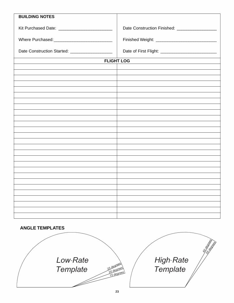
We recommend setting up your airplane according to thefollowing table as a starting point. Use the Angle Templatesincluded with the plane to verify that you are in the ballpark.However, setting up models of this type is largely a matter ofpersonal taste. We encourage you to tune the throws to yourtaste as you get more familiar with the aircraft. Many expert3D fliers choose to increase their high-rate travel by usinghigher endpoints.
If you are not able to achieve these control throws, double-check your pushrod hookup and make sure any controlsurfaces in question are operating smoothly. If you have acomputer radio, also make sure your endpoint adjustmentsare properly set.
At this stage the model should be in ready-to-fly conditionwith all of the systems in place including the motor, thepropeller, the battery, and the radio system.
❏ 1. Use a felt-tip pen or 3 mm [1/8"]-wide tape to accuratelymark the C.G. on the underside of the top wing on both sidesof the fuselage. The C.G. is located 83 mm [3-1/4"] back fromthe leading edge of the wing at the fuselage.
❏ 2. With all parts of the model installed, including thebattery and propeller (ready to fly), lift it on your fingertips atthe balance point you marked.
❏ 3. If the tail drops, the model is “tail heavy” and thebattery pack and/or receiver must be shifted forward orweight must be added to the nose to balance. If the nosedrops, the model is “nose heavy” and the battery packand/or receiver must be shifted aft or weight must be addedto the tail to balance. If possible, relocate the battery pack onthe hook-and-loop strip to minimize or eliminate any
This is where your model should balance for the firstflights. Later, you may wish to experiment by shifting theC.G. up to 13 mm [1/2"] forward or 13 mm [1/2"] back tochange the flying characteristics. Moving the C.G. forwardmay improve the smoothness and stability, but the modelmay then require more speed for takeoff and make it moredifficult to slow for landing or 3D aerobatics. Moving theC.G. aft makes the model more maneuverable, but couldalso cause it to become too difficult to control. In any case,start at the recommended balance point. As with thethrows, though, we encourage you to experiment with theCG until the model flies to your taste.
More than any other factor, the C.G. (balance point) canhave the greatest effect on how a model flies, and maydetermine whether or not your first flight will besuccessful. If you value this model and wish to enjoy it formany flights, DO NOT OVERLOOK THIS IMPORTANTPROCEDURE. A model that is not properly balanced willbe unstable and possibly unflyable.
Balance the Model (C.G.)Set the Control Throws
18
additional ballast required. If additional weight is required,begin by placing incrementally increasing amounts of weighton the bottom of the horizontal fuselage until the modelbalances. Once you have determined the amount of weightrequired, it can be permanently attached.
❏ 4. IMPORTANT: If you found it necessary to add anyweight, recheck the C.G. after the weight has been installed.
❏ 1. With the wing level, lift the model by the motor propellershaft and the bottom of the fuse under the TE of the fin. Dothis several times.
❏ 2. If one wing always drops when you lift the model, it meansthat side is heavy. Balance the airplane by adding weight to theother wing tip. An airplane that has been laterally balancedwill track better in loops and other maneuvers.
No matter if you fly at an AMA sanctioned R/C club site or ifyou fly somewhere on your own, you should always haveyour name, address, telephone number and AMA numberon your model. It is required at all AMA R/C club flying sitesand AMA sanctioned flying events. Write this information onthe bottom of the wing with a fine felt-tip pen.
Follow the battery charging instructions that came with yourradio control system to charge the batteries.You should alwayscharge your transmitter batteries the night before you go flying,and at other times as recommended by the radio manufacturer.
Charge the flight battery using a charger designed forLithium Polymer batteries. Charging with any other type ofcharger is very dangerous, and may cause the batteries tocombust violently.
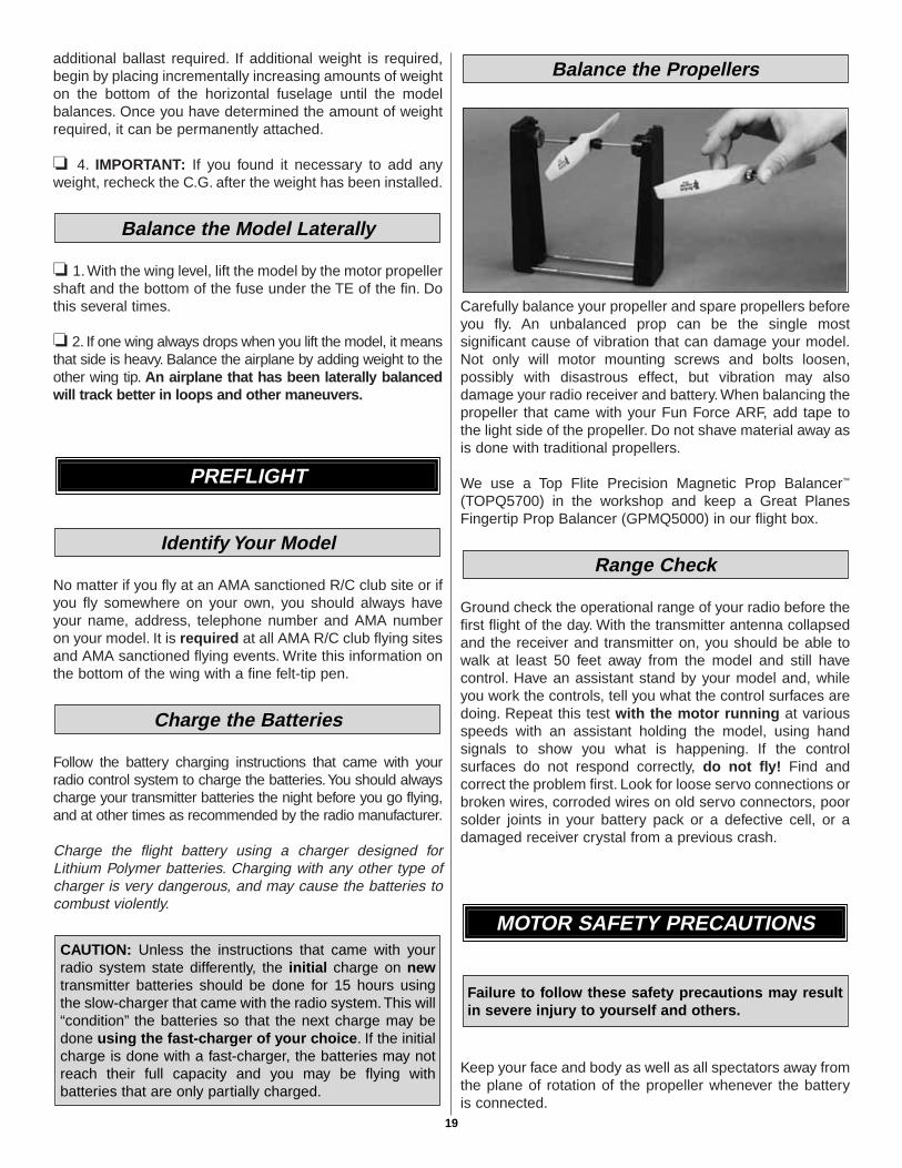
Carefully balance your propeller and spare propellers beforeyou fly. An unbalanced prop can be the single mostsignificant cause of vibration that can damage your model.Not only will motor mounting screws and bolts loosen,possibly with disastrous effect, but vibration may alsodamage your radio receiver and battery. When balancing thepropeller that came with your Fun Force ARF, add tape tothe light side of the propeller. Do not shave material away asis done with traditional propellers.
We use a Top Flite Precision Magnetic Prop Balancer™
(TOPQ5700) in the workshop and keep a Great PlanesFingertip Prop Balancer (GPMQ5000) in our flight box.
Ground check the operational range of your radio before thefirst flight of the day. With the transmitter antenna collapsedand the receiver and transmitter on, you should be able towalk at least 50 feet away from the model and still havecontrol. Have an assistant stand by your model and, whileyou work the controls, tell you what the control surfaces aredoing. Repeat this test with the motor running at variousspeeds with an assistant holding the model, using handsignals to show you what is happening. If the controlsurfaces do not respond correctly, do not fly! Find andcorrect the problem first. Look for loose servo connections orbroken wires, corroded wires on old servo connectors, poorsolder joints in your battery pack or a defective cell, or adamaged receiver crystal from a previous crash.
Keep your face and body as well as all spectators away fromthe plane of rotation of the propeller whenever the batteryis connected.
Failure to follow these safety precautions may resultin severe injury to yourself and others.
MOTOR SAFETY PRECAUTIONS
Range Check
Balance the Propellers
CAUTION: Unless the instructions that came with yourradio system state differently, the initial charge on newtransmitter batteries should be done for 15 hours usingthe slow-charger that came with the radio system.This will“condition” the batteries so that the next charge may bedone using the fast-charger of your choice. If the initialcharge is done with a fast-charger, the batteries may notreach their full capacity and you may be flying withbatteries that are only partially charged.
Charge the Batteries
Identify Your Model
PREFLIGHT
Balance the Model Laterally
19
Keep these items away from the prop: loose clothing, shirtsleeves, ties, scarfs, long hair or loose objects such aspencils or screwdrivers that may fall out of shirt or jacketpockets into the prop.
Read and abide by the following excerpts from the Academyof Model Aeronautics Safety Code. For the complete SafetyCode refer to Model Aviation magazine, the AMA web site orthe Code that came with your AMA license.
1) I will not fly my model aircraft in sanctioned events, airshows, or model flying demonstrations until it has beenproven to be airworthy by having been previously,successfully flight tested.
2) I will not fly my model aircraft higher than approximately400 feet within 3 miles of an airport without notifying theairport operator. I will give right-of-way and avoid flying in theproximity of full-scale aircraft. Where necessary, an observershall be utilized to supervise flying to avoid having modelsfly in the proximity of full-scale aircraft.
3) Where established, I will abide by the safety rules for theflying site I use, and I will not willfully and deliberately fly mymodels in a careless, reckless and/or dangerous manner.
5) I will not fly my model unless it is identified with my nameand address or AMA number, on or in the model. Note: Thisdoes not apply to models while being flown indoors.
7) I will not operate models with pyrotechnics (any devicethat explodes, burns, or propels a projectile of any kind).
1) I will have completed a successful radio equipment groundcheck before the first flight of a new or repaired model.
2) I will not fly my model aircraft in the presence ofspectators until I become a qualified flier, unless assisted byan experienced helper.
3) At all flying sites a straight or curved line(s) must beestablished in front of which all flying takes place with theother side for spectators. Only personnel involved with flyingthe aircraft are allowed at or in the front of the flight line.Intentional flying behind the flight line is prohibited.
4) I will operate my model using only radio control frequenciescurrently allowed by the Federal Communications Commission.
5) I will not knowingly operate my model within threemiles of any pre-existing flying site except inaccordance with the frequency sharing agreementlisted [in the complete AMA Safety Code].
9) Under no circumstances may a pilot or other person toucha powered model in flight; nor should any part of themodel other than the landing gear, intentionally touchthe ground, except while landing.
❏ 1. Check the C.G. according to the measurementsprovided in the manual.
❏ 2. Be certain the battery and receiver are securelymounted on the fuse.
❏ 3. Extend your receiver antenna and make sure itcannot get tangled in the prop.
❏ 4. Balance your model laterally as explained inthe instructions.
❏ 5. Make sure all hinges are securely glued in place.❏ 6. Confirm that all controls operate in the correct direction
and the throws are set up according to the manual.❏ 7. Make sure any servo wiring does not interfere with
other systems (servo arms, pushrods, etc.).❏ 8. Place your name, address, AMA number and
telephone number on your model.❏ 9. If you wish to photograph your model, do so before
your first flight.❏ 10. Range check your radio when you get to the flying site.
The FlatOuts R/C Universe Bipe is a great-flying model that fliessmoothly and predictably. The R/C Universe Bipe does not,however, possess the self-recovery characteristics of a primaryR/C trainer and should be flown only by experienced R/C pilots.
For the first flight, it is a good idea to have an assistantlaunch the airplane for you. This allows you to keep yourhands on the controls and immediately correct any trimproblems that are present.
Hand Launch
FLYING
During the last few moments of preparation your mind may beelsewhere anticipating the excitement of the first flight.Because of this, you may be more likely to overlook certainchecks and procedures that should be performed before themodel is flown. To help avoid this, a check list is provided tomake sure these important areas are not overlooked. Manyare covered in the instruction manual, so where appropriate,refer to the manual for complete instructions. Be sure to checkthe items off as they are completed.
CHECK LIST
Radio Control
General
AMA SAFETY CODE (excerpts)
20

21
Have your friend hold the FlatOuts R/C Universe Bipe by thecanopy. Throttle up to full power, and give the plane a gentle,underhanded toss at about a 30° angle upward. Since theR/C Universe Bipe has a very high thrust-to-weight ratio, theplane will accelerate to flying speed almost instantly. Climbto a comfortable height and throttle back to a lower powersetting. This plane flies great at about half-throttle when instandard forward flight.
Once you have the model trimmed out, the FlatOuts R/CUniverse Bipe is very capable of ROG (rise-off-ground)takeoffs from a smooth surface (parking lot, runway, gymfloor, etc.). To take off, start by advancing the throttle toabout two-thirds, making sure to correct any torquereactions with rudder. The plane will build flying speedalmost instantly due to its high thrust-to-weight ratio. Oncethe tail comes up, gently apply up elevator to break groundand climb out. Full throttle takeoffs are necessary only forextremely short runways.
When flying a 3D aerobat like the R/C Universe Bipe, thereare several things you should always keep in mind. First isthrottle management–this airplane has enough power toclimb straight up at full throttle, so level flight is morecomfortably achieved at about half-throttle. Avoid extremelyhigh-speed flight with the FlatOuts R/C Universe Bipe–it isdesigned for slow 3D aerobatics, and extended full-throttledives can result in wing flutter. While flutter won’t destroy theairplane, it’s best to avoid it. Second, take it easy on thecontrol sticks–with 3D throws, even a small stick deflectioncan result in a big response, so be gentle (unless of courseyou’re performing an aggressive maneuver).
Because this model is extremely lightweight, it slows rapidlywithout power, and performing standard gliding landings canbe difficult. Instead, land the model under power, with arolling 3-point landing as the goal. To achieve this, performyour landing approach with the model in the 3-point attitude(nose up at such an angle that all three wheels are level).Modulate your descent with the throttle, and use a quick“blip” of power just before touchdown to slow the descent fora gentle landing.
Have a ball! But always stay in control and fly in asafe manner.
GOOD LUCK AND GREAT FLYING!
ElectriFly FlatOuts Matt Chapman CAP 580 Based on the full-scale airshow favorite flown by MattChapman, this “flat foamie” is made the Great Planes way –straight, strong, easy on the eyes, and outrageous in 3Daction. A powerful T-370 brushed motor and gearbox areincluded and ready for installation. Also supplied are a slowfly propeller and prop saver that enables it to deflect atlanding. Using foam-safe CA and the supplied customhardware, you’ll easily assemble the pre-printed foampanels and carbon rods into a sturdy, great-looking 3Dmodel that excels at the low speeds and tight turns neededfor flying indoors. GPMA1112
ElectriFly FlatOuts Turmoil™
Accept no limitations! The Turmoil was specifically designedby Jason Noll for a mix of precision aerobatics and 3Dmaneuvers. Its unique Side Force Generators let you flyknife-edge almost hands-off. They also provide enough sidelift to perform loops, figure eights, and more, using nothingbut rudder. Flight-ready in only 2-3 hours, the Turmoilincludes a T-370 brushed motor with gearbox and slow-flyprop. Using the supplied custom hardware and foam-safeCA, you’ll easily assemble its colorful foam panels andcarbon rods into a strong, eye-catching model with provencontest-winning performance. GPMA1115
OTHER ITEMS AVAILABLE FROMGREAT PLANES
Landing
Flight
Rise-Off-Ground (ROG) Takeoffs

ElectriFly FlatOuts Reflection™
Go end-over-end with ease! If you’re looking for tumblingfun, the FlatOuts Reflection is your plane. Waterfalls,tumbles, and rolls are amazingly easy. With its shortwingspan and large ailerons, the roll rate is incredible. Flight-ready in only 2-3 hours, the Reflection includes a T-370brushed motor with gearbox and slow-fly prop (and is alsoavailable in a version without them, GPMA1140). Using thesupplied custom hardware and foam-safe CA, you’ll easilyassemble its colorful foam panels and carbon rods into astrong, eye-catching model that offers big returns inperformance for very little time and money. GPMA1116
Hobbico® Pro Series™ Accu-Cycle™ EliteAccu-Cycle Elite is an AC/DC charger, discharger and cyclerin one. It makes full, deep charges virtually effortless. Enterthe cell chemistry, voltage and capacity from your batterylabel, and its Auto Smart Set will automatically set thesafety-time-out period, charge current and dischargevoltage cut-off for Li-Ion/LiPo packs – and all three plus thetrickle rate for NiCds and NiMHs. You can also programcustom battery routines and store them in 10-batterymemory. It can handle a single cell or a pack; one of eachsimultaneously; or two cells or packs at once – even ifthey’re of different chemistries. The large, 2-line,16-character LCD make progress easy to see! HCAP0280
ElectriFly™ by Great Planes Triton Peak ChargerImagine a charger so versatile it can be used with lithium-ion
and lead-acid batteries as effectively as NiCd and NiMHcells. A unit that can peak charge tiny park flyer packs and24V car batteries alike. A charger that can discharge as wellas charge, cycle packs from 1 to 10 times automatically,memorize peak and average battery voltages for each cycle– and constantly display battery capacity, voltage, currentand time as each cycle progresses. Then, imagine that thecharger, which can do all this, is about the size of a thickpaperback book, and weighs just over a pound. Theadvanced computer technology in the Triton Peak Chargermakes it possible to accomplish all this and more, throughcontrols and menus so simple that programming is a breeze.For more information, log on at www.electrifly.com – andbe amazed. 1-year warranty. GPMM3150
Hobbico Pro Series Quick Field Charger MkIIThe MkII is two completely independent chargers in a singlecase! Current on both sides adjusts from 0.2-2A, to fastcharge 1-3 cell Li-Ion or LiPo park flyer batteries or peakcharge 1-8 cell NiCd or NiMH radio packs. Auto-trickle forNiCds and NiMH packs is automatically set, based on thefast-charge rate. Hook up the pack, press the start button –and twin LEDs signal the cell type and charge method to beused by color: red for NiCd, yellow for NiMH and green forLi-Ion or LiPo cells. Jacks make it easy to hook up your pack– and a voltmeter – to either side. HCAP0290
Hobbico 12V Power SupplyThe 12V Power Supply transforms 110V AC current intoconstant 13.8V 11.5A DC power for peak chargers, motorbreak-in and more. It includes fuse protection, 5V tap, a lightedon/off switch and one-year warranty protection. HCAP0250
22
23
ANGLE TEMPLATES
BUILDING NOTES
Kit Purchased Date: _______________________
Where Purchased:_________________________
Date Construction Started: __________________
Date Construction Finished: _________________
Finished Weight: __________________________
Date of First Flight: ________________________
FLIGHT LOG
