instruction manual - clay paky - professional lighting · instruction manual congratulations on...
TRANSCRIPT
1
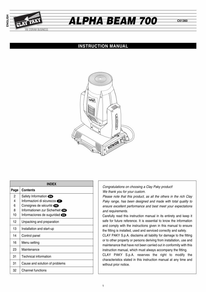
ALPHA BEAM 700 C61360
INSTRUCTION MANUAL
Congratulations on choosing a Clay Paky product! We thank you for your custom. Please note that this product, as all the others in the rich ClayPaky range, has been designed and made with total quality toensure excellent performance and best meet your expectationsand requirements.Carefully read this instruction manual in its entirety and keep itsafe for future reference. It is essential to know the informationand comply with the instructions given in this manual to ensurethe fitting is installed, used and serviced correctly and safely.CLAY PAKY S.p.A. disclaims all liability for damage to the fittingor to other property or persons deriving from installation, use andmaintenance that have not been carried out in conformity with thisinstruction manual, which must always accompany the fitting.CLAY PAKY S.p.A. reserves the right to modify thecharacteristics stated in this instruction manual at any time andwithout prior notice.
ENGLISH
INDEX
Page Contents
2 Safety Information4 Informazioni di sicurezza6 Consignes de sécurité8 Informationen zur Sicherheit10 Informaciones de suguridad
12 Unpacking and preparation
13 Installation and start-up
14 Control panel
16 Menu setting
23 Maintenance
31 Technical information
31 Cause and solution of problems
32 Channel functions
EN
IT
FR
DE
ES

2ALPHA BEAM 700
7.5700W
tc 150°C
Risk Group 2According toEN 62471
• InstallationMake sure all parts for fixing the projector are in a good state of repair.Make sure the point of anchorage is stable before positioning the projector.The safety chain must be properly hooked onto the fitting and secured to the framework, so that, if the primarysupport system fails, the fitting falls as little as possible. If the safety chain gets used, it needs to be replaced with a genuine spare.
• Minimum distance of illuminated objectsThe projector needs to be positioned so that the objects hit by the beam of light are at least 7.5 metres (24’ 7”) fromthe lens of the projector.
• Minimum distance from flammable materialsThe projector must be positioned so that any flammable materials are at least 0.20 metres (8”) from every point onthe surface of the fitting.
• Maximum ambient temperatureDo not operate the fixture if the ambient temperature (Ta) exceeds 40° C (104° F).
• IP20 protection ratingThe fitting is protected against penetration by solid bodies of over 12mm (0.47”) in diameter (first digit 2), but notagainst dripping water, rain, splashes or jets of water (second digit 0).
• Protection against electrical shockConnection must be made to a power supply system fitted with efficient earthing (Class I appliance according tostandard EN 60598-1). It is, moreover, recommended to protect the supply lines of the projectors from indirectcontact and/or shorting to earth by using appropriately sized residual current devices.
• Connection to mains supplyConnection to the electricity mains must be carried out by a qualified electrical installer.Check that the mains frequency and voltage correspond to those for which the projector is designed as given on theelectrical data label.This label also gives the input power to which you need to refer to evaluate the maximum number of fittings toconnect to the electricity line, in order to avoid overloading. IMPORTANT: to prevent EMI disturbances, in some condition it might be necessary to clip around the DMX and theEthernet cable, as close as possible to the projector, an appropriate ferrite bead. Shielded cables must always be used.
• Temperature of the external surfaceThe maximum temperature that can be reached on the external surface of the fitting, in a thermally steady state, is150°C (302°F).
• MaintenanceBefore starting any maintenance work or cleaning the projector, cut off power from the mains supply.After switching off, do not remove any parts of the fitting for at least 10 minutes. After this time the likelihood ofthe lamp exploding is virtually nill. If it is necessary to replace the lamp, wait for another 20 minutes to avoidgetting burnt.The fitting is designed to hold in any splinters produced by a lamp exploding. The lenses must be mounted and, ifvisibly damaged, they have to be replaced with genuine spares.
• LampThe fitting mounts a high-pressure lamp that needs an external igniter. This igniter is fitted onto the apparatus.- Carefully read the "operating instructions" provided by the lamp manufacturer.- Immediately replace the lamp if damaged or deformed by heat.
• Photobiological Safety CAUTION. Possibly hazardous optical radiation emitted from this product. Do not stare at operating lamp. May beharmful to the eyes. The fixture must be positioned so that the minimum distance between the front lens and humaneye is at least 1 metre to prevent personal photobiological risks.
This product is intended for the following areas of application:studios, stages, theaters, exhibitions, trade fairs, events, theme parks, entertainment venues, architectural lightingand similar.
SAFETY INFORMATION
IP20
ta 40°C
EN

3ALPHA BEAM 700
Not suitable for household illumination
Not for residential use
• BatteryThis product contains a rechargeable lead-acid or lithium iron tetraphosphate battery. To preserve the environment,please dispose the battery at the end of its life according to the regulation in force.
• DisposingThis product is supplied in compliance with European Directive 2012/19/EU - Waste Electrical and ElectronicEquipment (WEEE). To preserve the environment please dispose/recycle this product at the end of its life accordingto the local regulation.
LiFePO4 Pb
The products to which this manual refers comply with the European Directives pursuant to:• 2006/95/EC - Safety of electrical equipment supplied at low voltage (LVD)• 2004/108/EC - Electromagnetic Compatibility (EMC)• 2011/65/EU - Restriction of the use of certain hazardous substances (RoHS)• 2009/125/EC - EcoDesign requirements for Energy-related Products (ErP)

4ALPHA BEAM 700
INFORMAZIONI DI SICUREZZAIT
• InstallazioneAssicurarsi che tutte le parti per il fissaggio del proiettore siano in buona condizione.Assicurarsi della stabilità del punto di ancoraggio prima di posizionare il proiettore. La fune di sicurezza, debitamente agganciata all’apparecchio e fissata alla struttura di sostegno, deve essereinstallata in modo che, in caso di cedimento del sistema di supporto primario, si abbia la minor caduta possibiledell’apparecchio. Dopo un eventuale intervento la fune di sicurezza deve essere sostituita con il ricambio originale.
• Distanza minima degli oggetti illuminatiIl proiettore deve essere posizionato in modo tale che gli oggetti colpiti dal fascio luminoso siano distanti almeno 3metri dall’obiettivo del proiettore stesso.
• Distanza minima dei materiali infiammabiliIl proiettore deve essere posizionato in modo tale che i materiali infiammabili siano distanti almeno 0,20 metri daogni punto della superficie dell’apparecchio.
• Massima temperatura ambienteNon utilizzare il proiettiore se la temperatura ambiente (Ta) supera i 40°C.
• Grado di protezione IP20L’apparecchio è protetto contro la penetrazione di corpi solidi di dimensione superiore a 12mm (prima cifra 2),mentre teme lo stillicidio, la pioggia, gli spruzzi e i getti d’acqua (seconda cifra 0).
• Protezione contro la scossa elettricaÈ obbligatorio effettuare il collegamento ad un impianto di alimentazione dotato di un’efficiente messa a terra(apparecchio di Classe I secondo la norma EN 60598-1).Si raccomanda, inoltre, di proteggere le linee di alimentazione dei proiettori dai contatti indiretti e/o cortocircuitiverso massa tramite l’uso di interruttori differenziali opportunamente dimensionati.
• Collegamento alla rete di alimentazioneLe operazioni di collegamento alla rete di distribuzione dell’energia elettrica devono essere effettuate da uninstallatore elettrico qualificato. Verificare che frequenza e tensione della rete corrispondano alla frequenza ed allatensione per cui il proiettore è predisposto ed indicate sulla targhetta dei dati elettrici. Sulla medesima targhetta èpure indicata la potenza assorbita. Fare riferimento a quest’ultima per valutare il numero massimo di apparecchi dacollegare alla linea elettrica, al fine di evitare sovraccarichi.IMPORTANTE: per evitare l'insorgere di interferenze elettromagnetiche, in alcune situazioni può rendersinecessario avvolgere attorno al cavo DMX ed al cavo Ethernet, il più possibile vicino al proiettore, una ferriteappropriata. Usare sempre cavi schermati.
• Temperatura della superficie esternaLa temperatura massima raggiungibile sulla superficie esterna dell’apparecchio, in condizioni di regime termico, èdi 150°C.
• ManutenzionePrima di iniziare qualsiasi operazione di manutenzione o pulizia sul proiettore togliere la tensione dalla rete dialimentazione. Dopo lo spegnimento non rimuovere alcuna parte dell’apparecchio per 10 minuti. Trascorso taletempo la probabilità di esplosione della lampada è praticamente nulla. Se è necessario sostituire la lampada,aspettare ulteriori 20 minuti per evitare scottature. L’apparecchio è progettato in modo da trattenere le scheggeprodotte dall’eventuale scoppio della lampada. Le lenti devono essere obbligatoriamente montate; devono inoltre,se visibilmente danneggiate, essere sostituite con ricambi originali.
• LampadaL’apparecchio monta una lampada ad alta pressione che richiede un accenditore esterno. Tale accenditore è incorporato nell’apparecchio.- Leggere attentamente le “istruzioni d’uso” fornite dal costruttore della lampada.- Sostituire immediatamente la lampada se danneggiata o deformata dal calore.
• Sicurezza fotobiologicaATTENZIONE: Possibile radiazione ottica rischiosa emessa da questo prodotto.Non fissare la lampada in funzione. Può essere pericoloso per gli occhi.Il proiettore deve essere posizionato in modo tale che la minima distanza della lente del proiettore dall’occhioumano sia di almeno 1 metro per prevenire rischi fotobiologici alla persona.
tc 150°C
IP20
ta 40°C
Gruppo di rischio 2Secondo la norma
EN 62471
7.5700W
5ALPHA BEAM 700
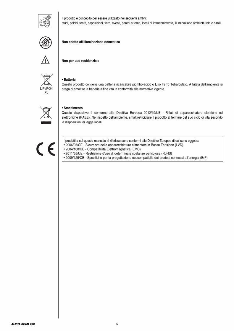
Il prodotto è concepito per essere utilizzato nei seguenti ambiti:studi, palchi, teatri, esposizioni, fiere, eventi, parchi a tema, locali di intrattenimento, illuminazione architetturale e simili.
Non adatto all'illuminazione domestica
Non per uso residenziale
• BatteriaQuesto prodotto contiene una batteria ricaricabile piombo-acido o Litio Ferro Tetrafosfato. A tutela dell'ambiente siprega di smaltire la batteria a fine vita in conformità alla normativa vigente.
• SmaltimentoQuesto dispositivo è conforme alla Direttiva Europea 2012/19/UE - Rifiuti di apparecchiature elettriche edelettroniche (RAEE). Nel rispetto dell'ambiente, smaltire/riciclare il prodotto al termine del suo ciclo di vita secondole disposizioni di legge locali.
LiFePO4 Pb
I prodotti a cui questo manuale si riferisce sono conformi alle Direttive Europee di cui sono oggetto:• 2006/95/CE - Sicurezza delle apparecchiature alimentate in Bassa Tensione (LVD)• 2004/108/CE - Compatibilità Elettromagnetica (EMC)• 2011/65/UE - Restrizione d’uso di determinate sostanze pericolose (RoHS)• 2009/125/CE - Specifiche per la progettazione ecocompatibile dei prodotti connessi all’energia (ErP)

6ALPHA BEAM 700
• InstallationS’assurer que toutes les pièces pour la fixation du projecteur sont en bon état.S’assurer de la stabilité du point d’ancrage avant de positionner le projecteur. Le câble de sécurité, à fixer correctement à l’appareil et à la structure de support, doit être installé de façon à ce que,en cas de rupture du système de support principal, la chute de l’appareil soit la plus limitée possible. Après uneéventuelle intervention du câble de sécurité suite à une chute, il faut le remplacer par une pièce de rechange d’origine.
• Distance minimum des objets éclairésLe projecteur doit être positionné de façon à ce que les objets éclairés par le faisceau lumineux soient à unedistance d’au moins 7.5 mètres de l’objectif du projecteur.
• Distance minimum des substances inflammablesLe projecteur doit être positionné de façon à ce qu’il y ait une distance d’au moins 0,20 mètre entre toute substanceinflammable et tout point de sa surface.
• Température ambiante maximumNe pas utiliser le projecteur quand la température ambiante (Ta) dépasse 40°C.
• Degré de protection IP20L’appareil est protégé contre la pénétration de corps solides de dimension supérieure à 12 mm (premier chiffre 2),tandis qu’il craint les gouttes d’eau, la pluie et les projections d’eau (deuxième chiffre 0).
• Protection contre l’électrisationL’appareil doit obligatoirement être branché à une installation d’alimentation équipée d’une mise à la terre efficace(appareil de Classe I selon la norme EN 60598-1).Nous recommandons également de protéger les lignes d’alimentation des projecteurs contre les contacts indirectset/ou les courts-circuits vers la masse en utilisant des interrupteurs différentiels de sensibilité adéquate.
• Branchement au réseau d’alimentationLes opérations de branchement au réseau de distribution de l’énergie électrique doivent être exécutées par uninstallateur électrique qualifié. Contrôler que la fréquence et la tension de réseau correspondent à la fréquence età la tension pour lesquelles le projecteur est prévu ; ces données sont indiquées sur la plaquette des donnéesélectriques. Cette même plaquette reporte également la puissance absorbée. Afin d’éviter des surcharges, seréférer à celle-ci pour évaluer le nombre maximum d’appareils à brancher à la ligne électrique.IMPORTANT : afin d’empêcher l’apparition de perturbations électromagnétiques, il peut s’avérer nécessaire danscertains cas d'accrocher autour du DMX et du câble Ethernet, le plus près possible du projecteur, un manchon deferrite approprié. Toujours utiliser des câbles blindés.
• Température de la surface extérieureLa température maximum qui peut être atteinte sur la surface extérieure de l’appareil, en conditions de régimethermique, est de 150°C.
• EntretienAvant de procéder à toute opération d’entretien ou de nettoyage sur le projecteur, couper la tension d’alimentation.Après avoir éteint le projecteur, ne démonter aucun élément de l’appareil pendant les 10 minutes qui suivent. Unefois ce temps écoulé, la probabilité d’explosion de la lampe est quasiment nulle. S’il faut remplacer la lampe,attendre encore 20 minutes afin d’éviter tout risque de brûlures.L’appareil a été conçu de façon à retenir les éclats produits en cas d’explosion de la lampe. Les lentilles doiventobligatoirement être montées sur l’appareil et doivent être remplacées par des pièces d’origine dès qu’elles sontvisiblement endommagées.
• LampeL’appareil fonctionne avec une lampe haute pression avec ballast externe. Ce dernier est incorporé dans l’appareil.- Lire avec attention les « instructions d’utilisation » fournies par le fabricant de la lampe.- Remplacer la lampe dès qu’elle est endommagée ou déformée par la chaleur
• Sécurité photobiologique ATTENTION : Possible radiation optique émise par ce produit.Ne pas fixer la lampe lorsqu’elle est allumée. Peut être dangereux pour les yeux. Le projecteur doit être positionnéde sorte que la distance minimum par rapport à l’œil humain de la lentille du projecteur soit de 1 mètre minimumpour prévenir des dangers photo-biologiques à la personne.
CONSIGNES DE SÉCURITÉFR
Classe dedangerosité 2Selon la normeEN 62471
tc 150°C
IP20
ta 40°C
7.5700W
7ALPHA BEAM 700
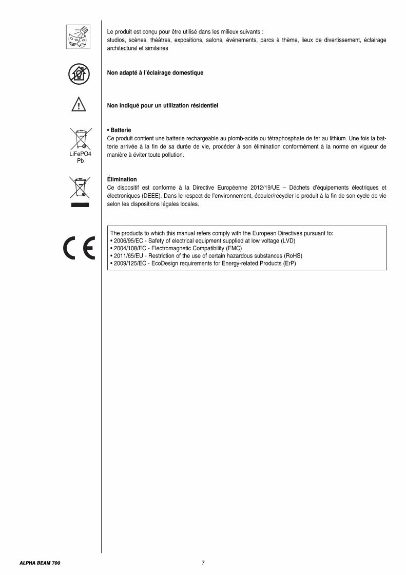
Le produit est conçu pour être utilisé dans les milieux suivants :studios, scènes, théâtres, expositions, salons, événements, parcs à thème, lieux de divertissement, éclairagearchitectural et similaires
Non adapté à l’éclairage domestique
Non indiqué pour un utilization résidentiel
• BatterieCe produit contient une batterie rechargeable au plomb-acide ou tétraphosphate de fer au lithium. Une fois la bat-terie arrivée à la fin de sa durée de vie, procéder à son élimination conformément à la no rme en vigueur demanière à éviter toute pollution.
Élimination Ce dispositif est conforme à la Directive Européenne 2012/19/UE – Déchets d’équipements électriques etélectroniques (DEEE). Dans le respect de l’environnement, écouler/recycler le produit à la fin de son cycle de vieselon les dispositions légales locales.
LiFePO4 Pb
The products to which this manual refers comply with the European Directives pursuant to:• 2006/95/EC - Safety of electrical equipment supplied at low voltage (LVD)• 2004/108/EC - Electromagnetic Compatibility (EMC)• 2011/65/EU - Restriction of the use of certain hazardous substances (RoHS)• 2009/125/EC - EcoDesign requirements for Energy-related Products (ErP)

8ALPHA BEAM 700
• InstallationSicherstellen, dass alle Teile für die Befestigung des Projektors in einwandfreiem Zustand sind.Vor der Installation des Projektors die Stabilität der Verankerungsstelle überprüfen. Das korrekt am Gerät eingehakte und an der Haltestruktur befestigte Sicherheitsseil muss so installiert werden,dass bei einem Nachgeben der Haupthalterung die Fallhöhe des Gerätes so gering wie möglich ist. Nach einemeventuellen Einsatz muss das Sicherheitsseil durch ein Originalersatzteil ersetzt werden.
• Mindestabstand zu beleuchteten ObjektenDer Projektor muss so installiert werden, dass der Abstand zwischen den vom Lichtstrahl beleuchteten Objektenund dem Objektiv des Projektors mindestens 7.5 Meter beträgt.
• Mindestabstand zu entzündbaren MaterialienDer Projektor muss so installiert werden, dass entzündbare Materialien mindestens 0,20 Meter von jedem Punkt derGeräteoberfläche entfernt sind.
• Max. RaumtemperaturDen Projektor nicht verwenden, wenn die Raumtemperatur (RT) 40°C überschreitet.
• Schutzart IP20Das Gerät ist gegen das Eindringen von festen Fremdkörpern mit Durchmesser über 12 mm (erste Kennziffer 2)geschützt, während es gegen Tropf,- Regen- und Spritzwasser sowie Wasserstrahlen (zweite Kennziffer 0)empfindlich ist.
• Schutz gegen StromschlagEs ist Pflicht, das Gerät an eine Stromversorgungsanlage anzuschließen, die mit einer leistungsfähigen Erdungausgestattet ist (Gerät der Klasse I gemäß Richtlinie EN 60598-1).Darüber hinaus wird empfohlen, die Zuleitungen der Projektoren mit korrekt bemessenenFehlerstromschutzschaltern vor indirekten Kontakten und/oder Kurzschlüssen zu schützen.
• NetzanschlussDer Anschluss an das Stromnetz muss von einem kompetenten Elektroinstallateur ausgeführt werden.Vergewissern Sie sich, dass Spannung und Frequenz der Netzversorgung mit den Werten übereinstimmen, für dieder Projektor ausgelegt ist und die auf dem Typenschild angegeben sind. Ebenfalls auf dem Typenschild ist dieLeistungsaufnahme angegeben. Um zu beurteilen, wie viele Geräte maximal an die Stromleitung angeschlossenwerden können, ist auf diese Angaben Bezug zu nehmen, damit Überlastungen vermieden werden.WICHTIG: Um das Auftreten von EMI-Störungen zu vermeiden, kann es in einigen Situationen notwendig werden,möglichst nahe am Scheinwerfer um die DMX und das Ethernet-Kabel eine geeignete Ferritperle anzubringen.Immer abgeschirmte Kabel verwenden.
• Temperatur der AußenflächeDie Außenfläche des Geräts kann im Wärmebetrieb eine Höchsttemperatur von 150°C erreichen.
• WartungVor Beginn von Wartungs- oder Reinigungsarbeiten am Projektor stets die Stromversorgung abschalten. Nach demAbschalten 10 Minuten lang keine Geräteteile abnehmen. Nach Ablauf dieser Zeit besteht praktisch keine Gefahrmehr, dass die Lampe birst. Falls die Lampe ersetzt werden muss, weitere 20 Minuten warten, umVerbrennungsgefahr zu vermeiden.Das Gerät wurde so konzipiert, dass es die Splitter bei einem eventuellen Bersten der Lampe zurückhält. DieMontage der Linsen ist obligatorisch vorgeschrieben; des Weiteren müssen sie bei sichtbarer Beschädigung durchOriginalersatzteile ersetzt werden.
• LampeDas Gerät ist mit einer Hochdrucklampe bestückt, die eine externe Zündeinheit verlangt. Diese Zündeinheit ist in das Gerät eingebaut.- Lesen Sie die vom Lampenhersteller gelieferte "Bedienungsanleitung" aufmerksam durch.- Eine beschädigte oder von der Hitze verformte Lampe muss sofort ersetzt werden.
• Photobiologische SicherheitACHTUNG: Mögliche riskante optische Strahlung wird von diesem Produkt abgegeben. Nicht die Lampe fixieren, wenn sie in Betrieb ist. Kann für die Augen gefährlich sein. Der Projektor muss so positio-niert werden, dass der Mindestabstand der Projektorlinse vom menschlichen Auge mindestens 1 Meter beträgt, umeiner fotobiologischen Gefährdung der Person vorzubeugen
INFORMATIONEN ZUR SICHERHEITDE
Gefahrenklasse 2Gemäß NormEN 62471
tc 150°C
IP20
ta 40°C
7.5700W

9ALPHA BEAM 700
Das Produkt wurde für die Verwendung in den folgenden Bereichen entwickelt:Studios, Bühnen, Theater, Ausstellungen, Messen, Veranstaltungen, Themenparks, Unterhaltungslokale,Architekturbeleuchtung oder ähnliches
Nicht für Haushaltsbeleuchtung geeignet
Nicht für den häuslichen Gebrauch
• BatterieDieses Produkt enthält eine wiederaufladbare Blei-Säure-Batterie oder Lithium-Eisen-tetraphosphat. ZumSchutz der Umwelt bitten wir Sie, diese Batterie, nachdem sie verbraucht ist, gemäß den geltendenVorschriften zu entsorgen.
EntsorgungDiese Vorrichtung entspricht der Europäischen Richtlinie 2012/19/UE - Abfall von elektrischen und elektronischenGerätschaften (RAEE). Das Produkt am Ende seines Lebenszyklus unter Berücksichtigung der Umwelt nach denlokalen Gesetzesvorschriften entsorgen/recyceln.
LiFePO4 Pb
The products to which this manual refers comply with the European Directives pursuant to:• 2006/95/EC - Safety of electrical equipment supplied at low voltage (LVD)• 2004/108/EC - Electromagnetic Compatibility (EMC)• 2011/65/EU - Restriction of the use of certain hazardous substances (RoHS)• 2009/125/EC - EcoDesign requirements for Energy-related Products (ErP)
10ALPHA BEAM 700
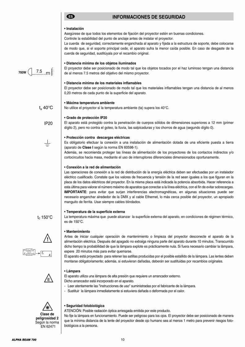
• InstalaciónAsegúrese de que todos los elementos de fijación del proyector estén en buenas condiciones.Controle la estabilidad del punto de anclaje antes de instalar el proyector. La cuerda de seguridad, correctamente enganchada al aparato y fijada a la estructura de soporte, debe colocarsede modo que, si el soporte principal cede, el aparato sufra la menor caída posible. En caso de desgaste de lacuerda de seguridad, sustitúyala por el recambio original.
• Distancia mínima de los objetos iluminadosEl proyector debe ser posicionado de modo tal que los objetos tocados por el haz luminoso tengan una distanciade al menos 7.5 metros del objetivo del mismo proyector.
• Distancia mínima de los materiales inflamablesEl proyector debe ser posicionado de modo tal que los materiales inflamables tengan una distancia de al menos0,20 metros de cada punto de la superficie del aparato.
• Máxima temperatura ambienteNo utilice el proyector si la temperatura ambiente (ta) supera los 40°C.
• Grado de protección IP20El aparato está protegido contra la penetración de cuerpos sólidos de dimensiones superiores a 12 mm (primerdígito 2), pero no contra el goteo, la lluvia, las salpicaduras y los chorros de agua (segundo dígito 0).
• Protección contra descargas eléctricasEs obligatorio efectuar la conexión a una instalación de alimentación dotada de una eficiente puesta a tierra(aparato de Clase I según la norma EN 60598-1).Además, se recomienda proteger las líneas de alimentación de los proyectores de los contactos indirectos y/ocortocircuitos hacia masa, mediante el uso de interruptores diferenciales dimensionados oportunamente.
• Conexión a la red de alimentaciónLas operaciones de conexión a la red de distribución de la energía eléctrica deben ser efectuadas por un instaladoreléctrico cualificado. Constate que los valores de frecuencia y tensión de la red sean iguales a los que figuran en laplaca de los datos eléctricos del proyector. En la misma placa está indicada la potencia absorbida. Hacer referencia aesta última para valorar el número máximo de aparatos que conectar a la línea eléctrica, con el fin de evitar sobrecargas.IMPORTANTE: para evitar que surjan interferencias electromagnéticas, en algunas situaciones puede sernecesario enganchar alrededor de la DMX y al cable Ethernet, lo más cerca posible del proyector, un apropiadomanguito de ferrita. Usar siempre cables blindados.
• Temperatura de la superficie externaLa temperatura máxima que puede alcanzar la superficie externa del aparato, en condiciones de régimen térmico,es de 150°C.
• MantenimientoAntes de iniciar cualquier operación de mantenimiento o limpieza del proyector desconecte el aparato de laalimentación eléctrica. Después del apagado no extraiga ninguna parte del aparato durante 10 minutos. Transcurridodicho tiempo la probabilidad de que la lámpara explote es prácticamente nula. Si fuera necesario cambiar la lámpara,espere 20 minutos más para evitar quemarse.El aparato está proyectado para retener las astillas producidas por el posible estallido de la lámpara. Las lentes debenmontarse obligatoriamente; además, si estuvieran dañadas, deberán ser sustituidas por recambios originales.
• LámparaEl aparato utiliza una lámpara de alta presión que requiere un arrancador externo. Dicho arrancador está incorporado en el aparato.- Leer atentamente las "instrucciones de uso" suministradas por el fabricante de la lámpara.- Sustituir la lámpara inmediatamente si estuviera dañada o deformada por el calor.
• Seguridad fotobiológicaATENCIÓN: Posible radiación óptica arriesgada emitida por este producto.No fije la lámpara en funcionamiento. Puede ser peligroso para los ojos. El proyector debe ser posicionado de maneraque la mínima distancia de la lente del proyector desde ojo humano sea al menos 1 metro para prevenir riesgos foto-biológicos a la persona.
INFORMACIONES DE SEGURIDADES
Clase depeligrosidad 2Según la norma
EN 62471
tc 150°C
IP20
ta 40°C
7.5700W

11ALPHA BEAM 700
El producto es concebido para ser utilizado en los siguientes ambientes:estudios, palcos, teatros, exposiciones, ferias, eventos, parques temáticos locales de entretenimiento, iluminaciónde arquitecturas y similares
No es apropiado para la iluminación doméstica
No para uso residencial
• BateríaEste producto contiene una batería recargable plomo-ácido o de litio tetrafosfato Hierro. Para proteger el ambientese ruega eliminar la batería conforme a la normativa vigente.
EliminaciónEste dispositivo es conforme a la Directiva Europea 2012/19/UE - Residuos de equipos eléctricos y electrónicos(RAEE). Con el fin de respetar el ambiente, eliminar/reciclar el producto al final de su ciclo de vida según lasdisposiciones de ley locales
LiFePO4 Pb
The products to which this manual refers comply with the European Directives pursuant to:• 2006/95/EC - Safety of electrical equipment supplied at low voltage (LVD)• 2004/108/EC - Electromagnetic Compatibility (EMC)• 2011/65/EU - Restriction of the use of certain hazardous substances (RoHS)• 2009/125/EC - EcoDesign requirements for Energy-related Products (ErP)

UNLOCKED
LOCKED
45°45
°45
° 45°45°
45°45°45
° 45°45°
45°45
°45
°
12ALPHA BEAM 700
UNPACKING AND PREPARATION
Lamp 700W(fitted into projector)099101
2 x 183102/805
1
90°
90° 90°
90°
LOCKED
UNLOCKED
PAN Mechanism Lock and Release (every 90°) - Fig. 2
TILT Mechanism Lock and Release (every 45°) - Fig. 3
2 3
Packing contents - Fig. 1
13ALPHA BEAM 700
4
1
23
2
1
5
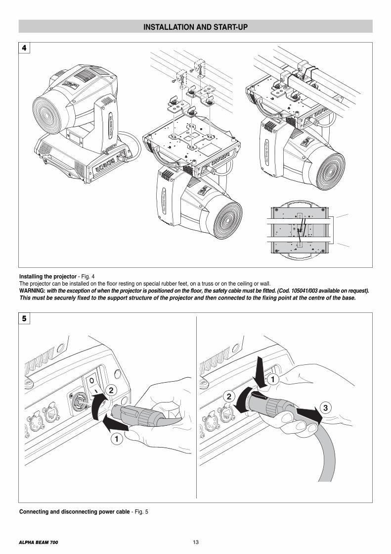
INSTALLATION AND START-UP
Connecting and disconnecting power cable - Fig. 5
Installing the projector - Fig. 4The projector can be installed on the floor resting on special rubber feet, on a truss or on the ceiling or wall. WARNING:with the exception of when the projector is positioned on the floor, the safety cable must be fitted. (Cod. 105041/003 available on request).This must be securely fixed to the support structure of the projector and then connected to the fixing point at the centre of the base.
14ALPHA BEAM 700
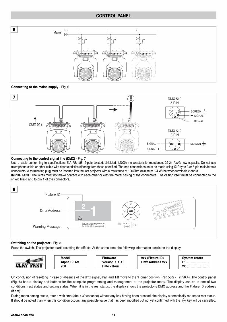
Switching on the projector - Fig. 8Press the switch. The projector starts resetting the effects. At the same time, the following information scrolls on the display:
Model Firmware xxx (Fixture ID) System errors Alpha BEAM Version X.X.X Dmx Address xxx E: ......................... 700 Date - Hour W: .........................
On conclusion of resetting in case of absence of the dmx signal, Pan and Tilt move to the “Home” position (Pan 50% - Tilt 50%). The control panel(Fig. 8) has a display and buttons for the complete programming and management of the projector menu. The display can be in one of twoconditions: rest status and setting status. When it is in the rest status, the display shows the projector’s DMX address and the Fixture ID address(if set). During menu setting status, after a wait time (about 30 seconds) without any key having been pressed, the display automatically returns to rest status.It should be noted than when this condition occurs, any possible value that has been modified but not yet confirmed with theF key will be cancelled.
CONTROL PANEL
12Dmx Address
Warning Message
Fixture ID8
Connecting to the control signal line (DMX) - Fig. 7Use a cable conforming to specifications EIA RS-485: 2-pole twisted, shielded, 120Ohm characteristic impedance, 22-24 AWG, low capacity. Do not usemicrophone cable or other cable with characteristics differing from those specified. The end connections must be made using XLR type 3 or 5-pin male/femaleconnectors. A terminating plug must be inserted into the last projector with a resistance of 120Ohm (minimum 1/4 W) between terminals 2 and 3.IMPORTANT: The wires must not make contact with each other or with the metal casing of the connectors. The casing itself must be connected to theshield braid and to pin 1 of the connectors.
Connecting to the mains supply - Fig. 6
LN
Mains6
7
SIGNAL
SCREEN
DMX 5125 PIN
12
345
SIGNAL
SCREEN13
2
DMX 5123 PIN
SIGNAL
SIGNAL
DMX 5125

ALPHA BEAM 700 15
28
28
Reversal of the display - Fig. 9To activate this function, press UP B and DOWN C keys simultaneously while the display is in the rest mode. This status will be memorised andmaintained even for the next time it will be switched on. To return to the initial state, repeat the operation all over again.Setting the projector starting addressOn each projector, the starting address must be set for the control signal (addresses from 1 to 512). The address can also be set with the projector switched off.Setting the address: see pag. 8.Setting the projector Fixture ID On each projector, the Fixture ID address must be set for an easy identification of the fixtures in an installation (ID from 1 to 255).The Fixture ID address can be set with the projector switched off.Setting the Fixture ID: see pag. 8.
9
Functions of the buttons - Using the menu
Setting addresses and options with the projector disconnectedThe projector’s DMX address, as well as other possible operating options, can also be set when the appliance is disconnected from the electricity supply.All that is needed is to pressF to momentarily activate the display and thus access the settings. Once the required operations have been carried out,the display will switch off again after a wait time of 30 seconds.
USING THE MENU:
1) Press F once – “Main Menu” appears on the display.2) Use the UP B and DOWN C keys to select the menu to be used:• Setup (Setup Menu): To set the setting options.• Option (Option Menu): To set the operating options• Informations (Informations Menu): To read the counters, software version and other information.• Manual Control (Manual control Menu): To trigger the test and manual control functions.• Test (Test Menu): To check the proper functionning of effects• Advanced (Advanced Menu): Access to the "Advanced menu" is recommended for a trained technical personnel.To enable the "Advanced" see pag.13
3)PressF to display the first item in the selected menu.4) Use the UP B and DOWN C keys to select the MENU items.
Confirms the displayed value, or activates the displayed function, or enters the successivemenu.
Decreases the value displayed (with auto-repetitions) or passes to the next item in the menu.
Increases the value displayed (with auto-repetitions) or passes to the previous item in a menu.
Return to the top level
Commute from units, tens, hundreds, in the "Address", "Fixture ID" and "Calibration" menù.
F
CDOWN
BUP
DLEFT
ERIGHT
Continue ➔

16ALPHA BEAM 700
MENU SETTING
Pan / Tilt
Colour
Beam
Gobo
All
Test
System Errors
Information
Fixture Hours
LampHours
4
LampManualControl
Reset
Channel
6
Set Up
Option
Information
ManualControl
Test
Advanced
1 3
LampStrikes
System Version
BoardDiagnost.
DmxMonitor
FansMonitor
Access code1234
Advanced
Calibration
UploadFirmware
SetupModel
5
2
Lamp Dmx
Color
Display
Option
InvertPan
InvertTilt
SwapPan-Tilt
EncoderPan-Tilt
ColorMixing
Fixed WheelShortcut
SettingDefaultPreset
UserPreset 1
UserPreset 2
UserPreset 3
ShutterShutterOn Error
Dimmer OnShutter
Power Mode 4-700W
Full fan speed
400WLow fan speed
4-700W Auto fan speed
DmxAddress
ChannelMode
EthernetInterface
Fixture ID
Sensorstatus
Networkparams
Colormixing curve
P/T Homingmode
Pan HomeDef Pos
Tilt Home Def Pos
Pan / Tilt

17ALPHA BEAM 700
DMX ADDRESSNOTE: without the DMX signal the Address (XXX) flashingAllows you to select the DMX ADDRESS.1) Press F - the current DMX Adress appear on the display.2) Use the UP B and DOWN C, RIGHT E keys to plan the DMXAddress.
3) Press F to confirm the selection or LEFT D to keep current settings.
CHANNEL MODEAllows you to select a channel arrangement from the two available.1) Press F - the current settings appear on the display (Standard orVector).
2) Use the UP B and DOWN C keys to select one of the followingsettings:- Standard- Vector
3) Press F to confirm the selection or LEFT D to keep current settings.
FIXTURE IDAllows you to select the FIXTURE ID.1) Press F - the current Fixture ID appear on the display.2) Use the UP B, DOWN C, RIGHT E keys to plan the Fixture ID.3) Press F to confirm the selection or LEFT D to keep current settings.
ETHERNET INTERFACEIt lets you set the Ethernet settings to be attributed to the projector.1) Premere F.2) Use the UP B and DOWN C keys to select the “Ethernet Interface”options to set:
Control ProtocolIt lets you select the “Control Protocol” Art-net to assign according to thecontrol unit used:1) Press F the current setting appears on the display.2) Use the UP B and DOWN C keys to select one of the following settings:- Disabled- Art-net on IP 2- Art-net on IP 10- Art-net Custom IP
3) Press F to confirm the selection or LEFT D to keep the current setting.If the Control Protocol option is set on Disabled, when an IP address(IP2, IP10 or IP Custom) is selected, the projector immediately initializesthe IP address that was just selected.If the Control Protocol option is enabled (IP2, IP10 or IP Custom) anda new one is selected that is different from the previous one, the projectormust be restarted so that it will be correctly initialized.
Repeat on DMXIt lets you enable the transmission of the Ethernet protocol by DMX signalto all the connected projectors.1) Press F the current setting appears on the display.2) Use the UP Band DOWN C keys to select one of the following settings:- Disabled: DMX transmission disabled.- Enabled on primary: DMX transmission enabled.
3) Press F to confirm the selection or LEFT D to keep the current setting.
UniverseIt lets you assign the “Universe” number to be assigned to a series ofprojectors.1) Press F – the current Universe address appears on the display.2) Use the UP B, DOWN C, RIGHT E keys to set the Universe address.3) Press F to confirm the selection or LEFT D to keep the current setting.
Custom IP addressAllows you to set the IP address manually by the user default.
Custom IP maskAllows you to set manually the Subnet Mask by the user default.
SET UP MENUNOTE: On grey the default options
Continue ➔
Custom IPaddress
Custom IPmask
Set UpDmx
Address
ChannelMode
Fixture ID
Address xxx
Standard
Vector
Value xxx
EthernetInterface
ControlProtocol
Repeat onDMX
Universe

18ALPHA BEAM 700
LAMP DMXUsed for enabling lamp remote control channel.1) Press F - the current settings appear on the display (On or Off).2) Use the UP B and DOWN C keys to enable (On) or disable (Off)the lamp remote control channel.
3) Press F to confirm the selection or LEFT D to keep current settings.
PAN / TILTInvert panUsed for reversing Pan movement.1) Press F - the current settings appear on the display (On or Off).2) Use the UP B and DOWN C keys to enable (On) or disable (Off)PAN inversion.
3) Press F to confirm the selection or LEFT D to keep current settings.
Invert tiltUsed for reversing tilt movement.1) PressF - the current settings appear on the display (On or Off).2) Use the UP B and DOWN C keys to enable (On) or disable (Off)Tilt inversion.
3) Press F to confirm the selection or LEFT D to keep current settings.
Swap Pan-TiltUsed for swapping Pan and Tilt channels (as well as Pan fine and Tilt fine).1) PressF - the current settings appear on the display (On or Off).2) Use the UP B and DOWN C keys to enable (On) or disable (Off)Pan and Tilt channel swap.
3) Press F to confirm the selection or LEFT D to keep current settings.
Encoder Pan-TiltUsed for enabling the Pan / Tilt encoders.1) PressF - the current settings appear on the display (On or Off).2) Use the UP B and DOWN C keys to enable (On) or disable (Off)Pan / Tilt encoders.
3) Press F to confirm the selection or LEFT D to keep current settings.You can quickly disable the Pan and Tilt Encoder by simultaneouslypressing the UP B and DOWN C keys in the ''Main Menu''.
P/T Homing ModeLets you set the initial projector Reset mode.1) Press F, the current setting appears on the display.2) Use the UP B and DOWN C keys to select one of the followingsettings:Standard: Pan & Tilt are simultaneously reset. Sequenced: Tilt is reset first followed by Pan.
3)Press F to confirm the selection or LEFT D to keep the current setting.
Pan Home Def PosLets you assign the Pan channel “home” position at the end of Reset,without a DMX input signal.1) Press F, the current setting appears on the display.2) Use the UP B and DOWN C keys to select one of the following settings:0 degree90 degrees180 degrees270 degrees (default)
3)Press F to confirm the selection or LEFT D to keep the current setting.
Tilt Home Def PosLets you assign the Tilt channel “home” position at the end of Reset,without a DMX input signal.1) PressF, the current setting appears on the display.2)Use the UP B and DOWN C keys to select one of the following settings: 0%12.5%25%50% (default)75%87.5%100%
3)Press F to confirm the selection or LEFT D to keep the current setting.
OPTIONS MENU
Pan / TiltInvertPan
On
Off
SwapPan-Tilt
On
Off
EncoderPan-Tilt
On
Off
InvertTilt
On
Off
P/T HomingMode
Standard
Sequenced
Pan HomeDef Pos
Tilt Home Def Pos
Lamp DmxOptionOn
Off
19ALPHA BEAM 700
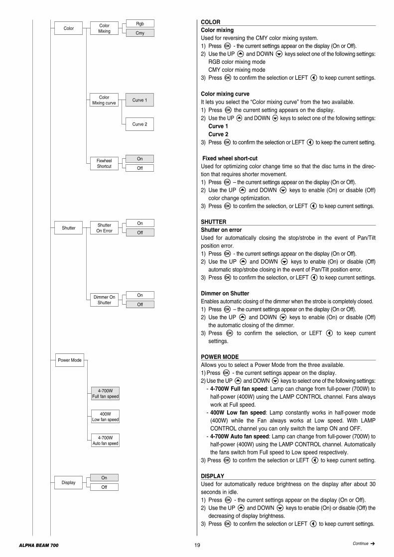
COLORColor mixingUsed for reversing the CMY color mixing system.1) PressF - the current settings appear on the display (On or Off).2) Use the UP B and DOWN C keys select one of the following settings:RGB color mixing modeCMY color mixing mode
3) Press F to confirm the selection or LEFT D to keep current settings.
Color mixing curveIt lets you select the “Color mixing curve” from the two available.1) Press F the current setting appears on the display.2) Use the UP B and DOWN C keys to select one of the following settings:Curve 1Curve 2
3) Press F to confirm the selection or LEFT D to keep the current setting.
Fixed wheel short-cutUsed for optimizing color change time so that the disc turns in the direc-tion that requires shorter movement.1) PressF – the current settings appear on the display (On or Off).2) Use the UP B and DOWN C keys to enable (On) or disable (Off)color change optimization.
3) Press F to confirm the selection, or LEFT D to keep current settings.
SHUTTERShutter on errorUsed for automatically closing the stop/strobe in the event of Pan/Tiltposition error.1) PressF - the current settings appear on the display (On or Off).2) Use the UP B and DOWN C keys to enable (On) or disable (Off)automatic stop/strobe closing in the event of Pan/Tilt position error.
3) PressF to confirm the selection, or LEFT D to keep current settings.
Dimmer on ShutterEnables automatic closing of the dimmer when the strobe is completely closed.1) PressF – the current settings appear on the display (On or Off).2) Use the UP B and DOWN C keys to enable (On) or disable (Off)the automatic closing of the dimmer.
3) Press F to confirm the selection, or LEFT D to keep currentsettings.
POWER MODEAllows you to select a Power Mode from the three available.1) Press F - the current settings appear on the display.2)Use the UP B and DOWN C keys to select one of the following settings:- 4-700W Full fan speed: Lamp can change from full-power (700W) tohalf-power (400W) using the LAMP CONTROL channel. Fans alwayswork at Full speed.- 400W Low fan speed: Lamp constantly works in half-power mode(400W) while the Fan always works at Low speed. With LAMPCONTROL channel you can only switch the lamp ON and OFF.- 4-700W Auto fan speed: Lamp can change from full-power (700W) tohalf-power (400W) using the LAMP CONTROL channel. Automaticallythe fans switch from Full speed to Low speed respectively.
3) PressF to confirm the selection or LEFT D to keep current setting.
DISPLAYUsed for automatically reduce brightness on the display after about 30seconds in idle. 1) Press F - the current settings appear on the display (On or Off).2) Use the UP B and DOWN C keys to enable (On) or disable (Off) thedecreasing of display brightness.
3) Press F to confirm the selection or LEFT D to keep current settings.
ColorColorMixing
Rgb
Cmy
Fixwheel Shortcut
On
Off
ColorMixing curve
Curve 1
Curve 2
ShutterShutterOn Error
On
Off
Dimmer On Shutter
On
Off
Power Mode
4-700W Full fan speed
400WLow fan speed
4-700W Auto fan speed
On
OffDisplay
Continue ➔
20ALPHA BEAM 700
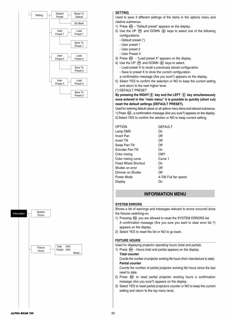
SETTINGUsed to save 3 different settings of the items in the options menu andrelative submenus.1) Press F - “Default preset” appears on the display.2) Use the UP B and DOWN C keys to select one of the followingconfigurations:- Default preset (*)- User preset 1- User preset 2- User Preset 3
3) Press F - “Load preset X” appears on the display.4) Use the UP B and DOWN C keys to select:- Load preset X to recall a previously stored configuration.- Save to preset X to store the current configuration.a confirmation message (Are you sure?) appears on the display.
5) Select YES to confirm the selection or NO to keep the current settingand return to the next higher level.
(*) DEFAULT PRESET By pressing the RIGHTE key and the LEFTD key simultaneouslyonce entered in the "main menu" it is possible to quickly (short cut)reset the default settings (DEFAULT PRESET).Used for restoring default values on all options menu items and relevant submenus.1) PressF, a confirmation message (Are you sure?) appears on the display.2) Select YES to confirm the selction or NO to keep current setting.
OPTION DEFAULTLamp DMX OnInvert Pan OffInvert Tilt OffSwap Pan-Tilt OffEncoder Pan-Tilt OnColor mixing CMYColor mixing curve Curve 1Fixed Wheel Shortcut OnShutter on error OffDimmer on Shutter OffPower Mode 4-700 Full fan speedDisplay On
SYSTEM ERRORSShows a list of warnings and messages relevant to errors occurred sincethe fixtures switching-on.1) Pressing F you are allowed to reset the SYSTEM ERRORS list.A confirmation message (Are you sure you want to clear error list ?)appears on the display.
2) Select YES to reset the list or NO to go back.
FIXTURE HOURSUsed for displaying projector operating hours (total and partial).1) Press F - Hours total and partial appears on the display.Total counterCounts the number of projector working life hours (from manufacture to date). Partial counterCounts the number of partial projector working life hours since the lastreset to date.
2) Press F to reset partial projector working hours a confirmationmessage (Are you sure?) appears on the display.
3) Select YES to reset partial projectors counter or NO to keep the currentsetting and return to the top menu level.
INFORMATION MENU
Save ToPreset 3
Reset ToDafault
Go Back
SettingDefaultPreset
Load Preset 1
Save ToPreset 1
UserPreset 1
Load Preset 2
Save ToPreset 2
UserPreset 2
Load Preset 3
UserPreset 3
InformationSystem Errors
Fixture Hours
Total XXXPartial XXX
Reset...
21ALPHA BEAM 700
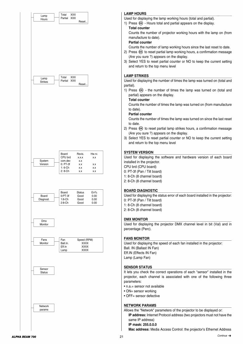
LAMP HOURSUsed for displaying the lamp working hours (total and partial).1) Press F - Hours total and partial appears on the display.Total counterCounts the number of projector working hours with the lamp on (frommanufacture to date). Partial counterCounts the number of lamp working hours since the last reset to date.
2) Press F to reset partial lamp working hours, a confirmation message(Are you sure ?) appears on the display.
3) Select YES to reset partial counter or NO to keep the current settingand return to the top menu level
LAMP STRIKESUsed for displaying the number of times the lamp was turned on (total andpartial).1) Press F - the number of times the lamp was turned on (total andpartial) appears on the display.Total counterCounts the number of times the lamp was turned on (from manufactureto date).Partial counterCounts the number of times the lamp was turned on since the last resetto date.
2) Press F to reset partial lamp strikes hours, a confirmation message(Are you sure ?) appears on the display.
3) Select YES to reset partial counter or NO to keep the current settingand return to the top menu level
SYSTEM VERSIONUsed for displaying the software and hardware version of each boardinstalled in the projector.CPU brd (CPU board)0: PT-3f (Pan / Tilt board)1: 8-Ch (8 channel board)2: 8-Ch (8 channel board)
BOARD DIAGNOSTICUsed for displaying the status error of each board installed in the projector:0: PT-3f (Pan / Tilt board)1: 8-Ch (8 channel board)2: 8-Ch (8 channel board)
DMX MONITORUsed for displaying the projector DMX channel level in bit (Val) and inpercentage (Perc).
FANS MONITORUsed for displaying the speed of each fan installed in the projector:Ball. IN (Ballast IN Fan)Eff.IN (Effects IN Fan)Lamp (Lamp Fan)
SENSOR STATUSIt lets you check the correct operations of each "sensor” installed in theprojector, each channel is associated with one of the following threeparameters:• n.a.= sensor not available• ON= sensor working• OFF= sensor defective
NETWORK PARAMSAllows the "Network" parameters of the projector to be displayed or:IP address: Internet Protocol address (two projectors must not have thesame IP address)IP mask: 255.0.0.0 Mac address: Media Access Control: the projector’s Ethernet Address
LampStrikes
Total XXXPartial XXX
Reset...
LampHours
Total XXXPartial XXX
Reset...
Networkparams
Sensor Status
System Version
Board Revis. Hw.rv.CPU brd x.x.x x.xcom.dev x.x0: PT-3f x.x x.x1: 6-Ch x.x x.x2: 8-Ch x.x x.x
BoardDiagnost.
DmxMonitor
Board Status Err%0:PT-3f Good 0.001:6-Ch Good 0.002:8-Ch Good 0.00
FansMonitor
Fan Speed (RPM)Ball.In. XXXXEff.In XXXXLamp XXXX
Continue ➔
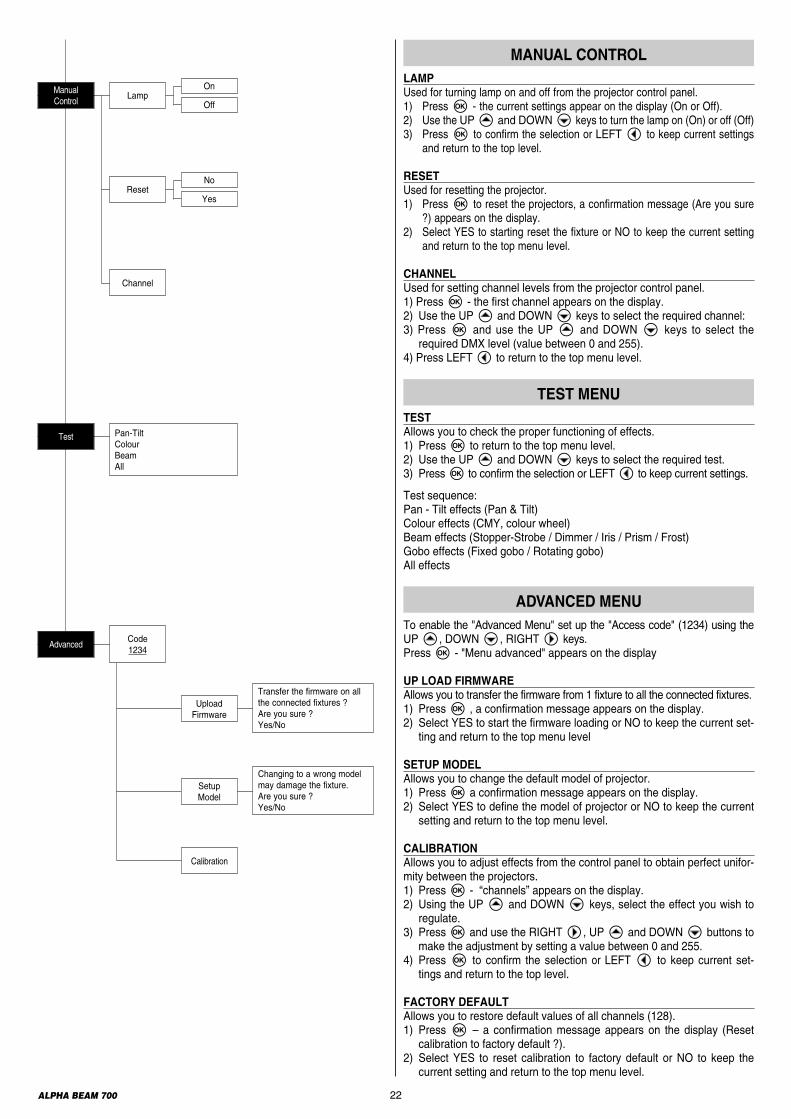
To enable the "Advanced Menu" set up the "Access code" (1234) using theUP B, DOWN C, RIGHT E keys.PressF - "Menu advanced" appears on the display
UP LOAD FIRMWAREAllows you to transfer the firmware from 1 fixture to all the connected fixtures.1) PressF , a confirmation message appears on the display.2) Select YES to start the firmware loading or NO to keep the current set-ting and return to the top menu level
SETUP MODELAllows you to change the default model of projector.1) PressF a confirmation message appears on the display.2) Select YES to define the model of projector or NO to keep the currentsetting and return to the top menu level.
CALIBRATIONAllows you to adjust effects from the control panel to obtain perfect unifor-mity between the projectors.1) PressF - “channels” appears on the display. 2) Using the UP B and DOWN C keys, select the effect you wish toregulate.
3) PressF and use the RIGHT E, UP B and DOWN C buttons tomake the adjustment by setting a value between 0 and 255.
4) PressF to confirm the selection or LEFT D to keep current set-tings and return to the top level.
FACTORY DEFAULTAllows you to restore default values of all channels (128).1) PressF – a confirmation message appears on the display (Resetcalibration to factory default ?).
2) Select YES to reset calibration to factory default or NO to keep thecurrent setting and return to the top menu level.
TESTAllows you to check the proper functioning of effects.1) Press F to return to the top menu level.2) Use the UP B and DOWN C keys to select the required test.3) Press F to confirm the selection or LEFT D to keep current settings.
Test sequence:Pan - Tilt effects (Pan & Tilt)Colour effects (CMY, colour wheel)Beam effects (Stopper-Strobe / Dimmer / Iris / Prism / Frost) Gobo effects (Fixed gobo / Rotating gobo)All effects
ADVANCED MENU
22ALPHA BEAM 700
LAMPUsed for turning lamp on and off from the projector control panel.1) PressF - the current settings appear on the display (On or Off).2) Use the UP B and DOWN C keys to turn the lamp on (On) or off (Off) 3) PressF to confirm the selection or LEFT D to keep current settings
and return to the top level.
RESETUsed for resetting the projector.1) PressF to reset the projectors, a confirmation message (Are you sure
?) appears on the display.2) Select YES to starting reset the fixture or NO to keep the current setting
and return to the top menu level.
CHANNELUsed for setting channel levels from the projector control panel.1) Press F - the first channel appears on the display.2) Use the UP B and DOWN C keys to select the required channel:3) Press F and use the UP B and DOWN C keys to select therequired DMX level (value between 0 and 255).
4) Press LEFT D to return to the top menu level.
TEST MENU
MANUAL CONTROL
Calibration
LampManualControl
On
Off
No
YesReset
Test Pan-Tilt Colour Beam All
Channel
AdvancedCode1234
UploadFirmware
Transfer the firmware on allthe connected fixtures ?Are you sure ?Yes/No
SetupModel
Changing to a wrong modelmay damage the fixture.Are you sure ?Yes/No

23ALPHA BEAM 700
Locking and releasing Pan and Tilt movements - Refer to the instructions in the UNPACKING AND PREPARATION section.Opening the head covers - Fig. 10.
Closing the head covers - Fig. 11.
2 1
1/4 Turn
1
2
1/4 Turn3
4
10 11
MAINTENANCE
Continue ➔
24ALPHA BEAM 700
Lower Side
Upper Side
2
Lower SideA
Upper Side
1
A
3A
13
14
1
2
12
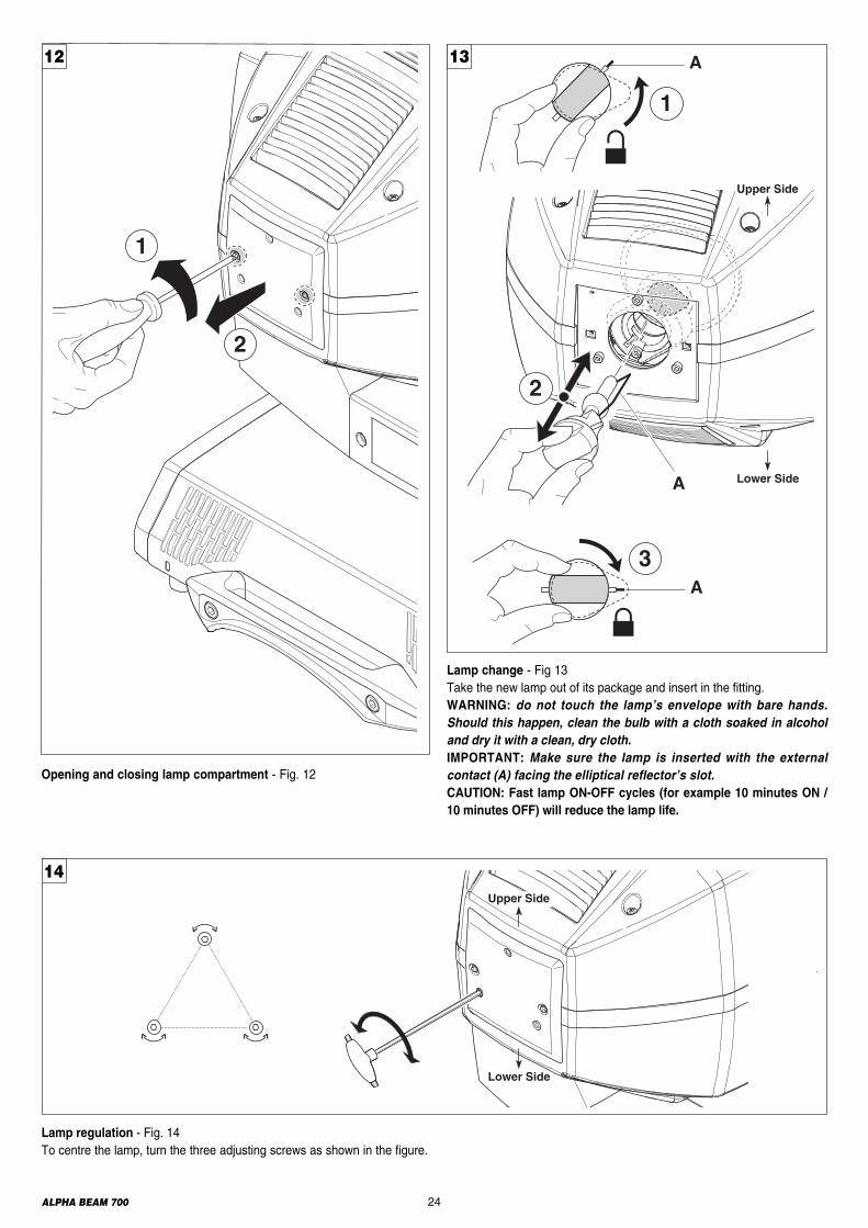
Lamp change - Fig 13Take the new lamp out of its package and insert in the fitting.WARNING: do not touch the lamp’s envelope with bare hands.Should this happen, clean the bulb with a cloth soaked in alcoholand dry it with a clean, dry cloth.IMPORTANT: Make sure the lamp is inserted with the externalcontact (A) facing the elliptical reflector’s slot.CAUTION: Fast lamp ON-OFF cycles (for example 10 minutes ON /10 minutes OFF) will reduce the lamp life.
Lamp regulation - Fig. 14To centre the lamp, turn the three adjusting screws as shown in the figure.
Opening and closing lamp compartment - Fig. 12

25ALPHA BEAM 700
1
2
084702/001
085601/001
085909/001
085603/001
085801/001
085910/001
085802/001
085606/001
Upper Side
15
Replacing fixed gobos (ø 31.5 mm – max 25 mm image – thickness max 1.1 mm) - Fig. 15WARNING: Before using personalised gobos contact Clay Paky.
Continue ➔

26ALPHA BEAM 700
Upper Side
21
085523/001 085506/001
085528/001
085527/001
085526/001
085525/001
085524/001
1
2
17
Replacing rotating gobos (ø 25.7 mm - max 23 mm image – thickness max 1.1 mm) - Fig. 17IMPORTANT: Use only glass gobos on the rotating gobos wheels. WARNING: Before using personalised gobos contact Clay Paky.
Bearing group replacement - Fig. 16
16
COATED GLASS GOBOS TYPE 1 COATED GLASS GOBOS TYPE 2
Grey/Black side away from lamp
Reflective side towards lamp
Coated side towards lamp
Uncoated side
Coated side
Uncoated side
18
To determine which side of a godo is coated, hold an odject up to it. Onthe uncoated side, there is a space between the object and its reflection.
Gobo orientation - Fig. 18The pictures shown the correct gobos orientation.
27ALPHA BEAM 700
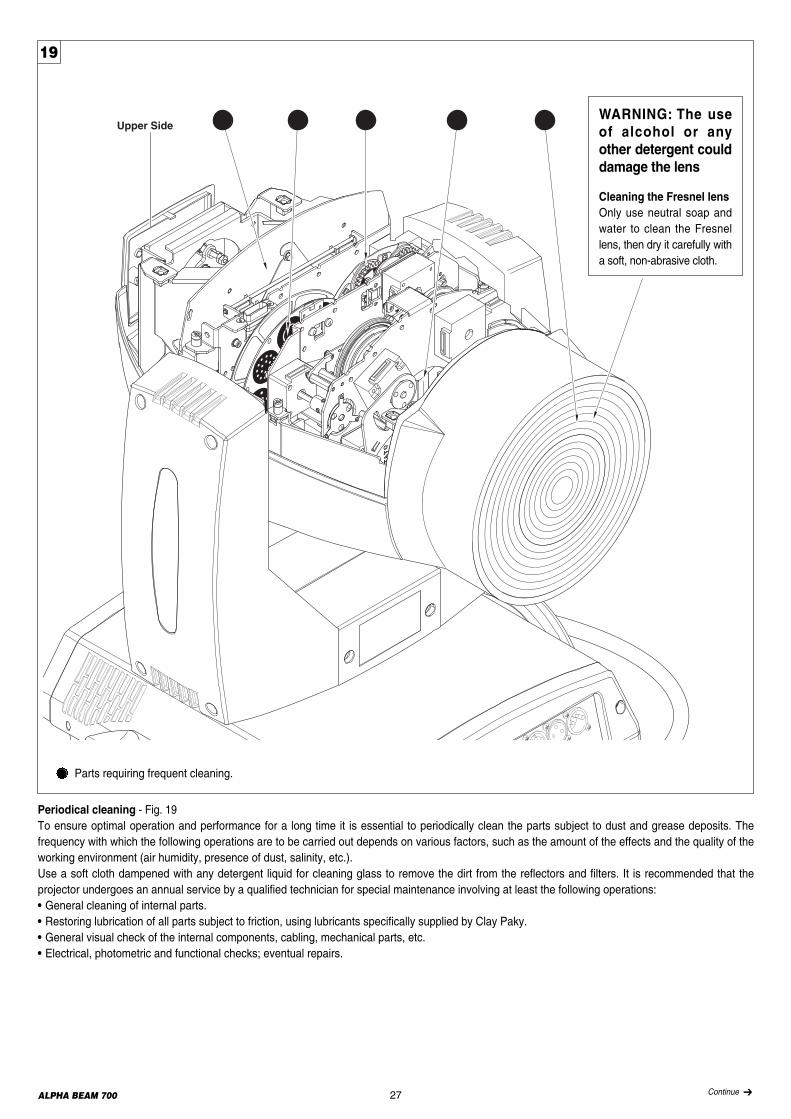
Periodical cleaning - Fig. 19To ensure optimal operation and performance for a long time it is essential to periodically clean the parts subject to dust and grease deposits. Thefrequency with which the following operations are to be carried out depends on various factors, such as the amount of the effects and the quality of theworking environment (air humidity, presence of dust, salinity, etc.).Use a soft cloth dampened with any detergent liquid for cleaning glass to remove the dirt from the reflectors and filters. It is recommended that theprojector undergoes an annual service by a qualified technician for special maintenance involving at least the following operations:• General cleaning of internal parts.• Restoring lubrication of all parts subject to friction, using lubricants specifically supplied by Clay Paky.• General visual check of the internal components, cabling, mechanical parts, etc.• Electrical, photometric and functional checks; eventual repairs.
Upper Side
19
Parts requiring frequent cleaning.
WARNING: The use of alcohol or anyother detergent couldda mage the lens
Cleaning the Fresnel lensOnly use neutral soap andwater to clean the Fresnellens, then dry it carefully witha soft, non-abrasive cloth.
Continue ➔

28ALPHA BEAM 700
Lower Side
2
4
3
Upper Side1
thermostat
20
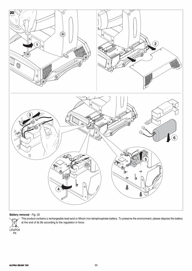
Extraction of the effect modules: Preliminary operations - Fig. 20

29ALPHA BEAM 700
Extraction of the effect modules - Fig. 21IMPORTANT: Grasp the modules using the support structure and not the details which could get damaged.Insertion of the effect modules: Repeat the operations indicated in Fig. 20 and 21 in reverse order.
Lower Side
3
1
Upper Side 2Upper Side
8
4
Upper Side
5
21
Continue ➔
30ALPHA BEAM 700
6
4
3
5
1 2
Battery removal - Fig. 20This product contains a rechargeable lead-acid or lithium iron tetraphosphate battery. To preserve the environment, please dispose the batteryat the end of its life according to the regulation in force.
LiFePO4 Pb
20

31ALPHA BEAM 700
405(15.94")
385(15.16")
390(15.35")
220(8.66")
635(25.00")
435(17.13")
505(19.88")
520(20.47")
Power supplies available100-120V 50/60Hz200-240V 50/60Hz
Input power• 1050VA a 230V 50Hz.
Lamp:Discharge lamp.• Type MSR Gold 700/2 Mini Fast Fit (L10098)- Cap PGJX28- Colour temperature 7250 K- Luminous flux 50000 lm- Average life 750 h- Any working position
• Type MSR Gold 700/1 Mini Fast Fit (LAM003)- Cap PGJX28- Colour temperature 5700 K- Luminous flux 54000 lm- Average life 750 h- Any working position
• Type Lok-it HTI 700W-60-P28 (LAM005)- Cap PGJX28- Colour temperature 6000 K- Luminous flux 50000 lm- Average life 750 h- Any working position
Motors19 stepper motors, operating with microsteps,totally microprocessor controlled.
Optical unit• Elliptic reflector with high luminous efficiency
Channels Max 26 control channels.
Inputs • DMX 512•Ethernet
Moving head•Movement by means of two stepper motors, con-trolled by microprocessor.• Automatic repositioning of PAN and TILT afteraccidental movement not controlled by controlunit.• Travel:- PAN = 540°- TILT = 250°• Maximum speeds:- PAN = 3.20 (Normal) / 2.90 (Fast)- TILT = 1.89 (normal) / 1.75 (Fast) • Resolution:- PAN = 2.11° - PAN FINE = 0.008°- TILT = 0.98°- TILT FINE = 0.004°
IP20 protection rating• Protected against the entry of solid bodies largerthan 12mm (0.47”).• No protection against the entry of liquids.
CE MarkingIn conformity with the European Union Low VoltageDirective 2006/95/CE and Electromagnetic compa-tibility Directive 2004/108/CE.
Safety Devices• Bipolar circuit breaker with thermal protection.• Automatic break in power supply in case ofoverheating or failed operation of cooling system.
CoolingForced ventilation with axial fans.
Body• Aluminium structure with die-cast plastic cover.• Two side handles for transportation.• Device locking PAN and TILT mechanisms fortransportation and maintenance.
Working positionWorking in any position.
Weight• 20.80 Kg (45lbs 12ozs).
TECHNICAL INFORMATION
CAUSE AND SOLUTION OF PROBLEMS
THE PROJECTOR WILL NOT SWITCH ON
PROBLEMSELECTRONICS NON-OPERATIONAL
DEFECTIVE PROJECTION
REDUCED LUMINOSITY
POSSIBLE CAUSES CHECKS AND REMEDIESNo mains supply.Lamp exhausted or defective.Signal transmission cable faulty or disconnected.Incorrect addressing.Fault in the electronic circuits.Lenses or reflector brokenDust or grease deposited.
Check the power supply voltage.Replace the lamp. (See instructions).Replace the cables.Check addresses (see instructions).Call an authorised technician.Call an authorised technician.Clean (see instructions).
32ALPHA BEAM 700
ALPHA BEAM 700
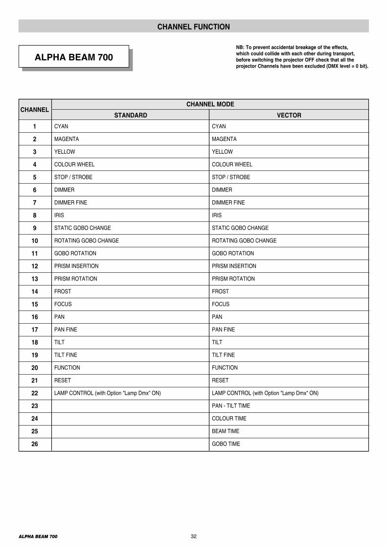
CHANNEL FUNCTION
CHANNELSTANDARD VECTOR
CHANNEL MODE
CYAN
MAGENTA
YELLOW
COLOUR WHEEL
STOP / STROBE
DIMMER
DIMMER FINE
IRIS
STATIC GOBO CHANGE
ROTATING GOBO CHANGE
GOBO ROTATION
PRISM INSERTION
PRISM ROTATION
FROST
FOCUS
PAN
PAN FINE
TILT
TILT FINE
FUNCTION
RESET
LAMP CONTROL (with Option "Lamp Dmx" ON)
1
2
3
4
5
6
7
8
9
10
11
12
13
14
15
16
17
18
19
20
21
22
23
24
25
26
CYAN
MAGENTA
YELLOW
COLOUR WHEEL
STOP / STROBE
DIMMER
DIMMER FINE
IRIS
STATIC GOBO CHANGE
ROTATING GOBO CHANGE
GOBO ROTATION
PRISM INSERTION
PRISM ROTATION
FROST
FOCUS
PAN
PAN FINE
TILT
TILT FINE
FUNCTION
RESET
LAMP CONTROL (with Option "Lamp Dmx" ON)
PAN - TILT TIME
COLOUR TIME
BEAM TIME
GOBO TIME
NB: To prevent accidental breakage of the effects, which could collide with each other during transport,before switching the projector OFF check that all theprojector Channels have been excluded (DMX level = 0 bit).
ALPHA BEAM 700
BIT EFFECT
255 COLOUR EXCLUDED
0 COLOUR INSERTED
CHANNEL 1
CYAN
CHANNEL 2
MAGENTA
CHANNEL 3
YELLOW
BIT EFFECT
255 COLOUR INSERTED
0 COLOUR EXCLUDED
CHANNEL 1
CYAN
CHANNEL 2
MAGENTA
CHANNEL 3
YELLOW
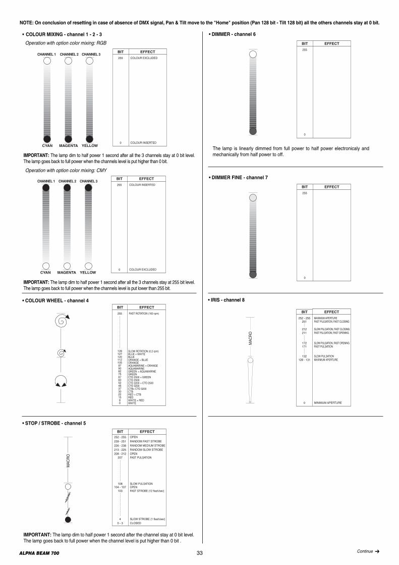
• COLOUR MIXING - channel 1 - 2 - 3
Operation with option color mixing: RGB
Operation with option color mixing: CMY
• COLOUR WHEEL - channel 4BIT EFFECT
255 FAST ROTATION (160 rpm)
12812712011210597908275676052453730221580
SLOW ROTATION (0.2 rpm)BLUE + WHITEBLUEORANGE + BLUEORANGEAQUAMARINE + ORANGEAQUAMARINEGREEN + AQUAMARINEGREENCTO 2500 + GREENCTO 2500CTO 3200 + CTO 2500CTO 3200CTB+ CTO 3200CTBRED + CTBREDWHITE + REDWHITE
IMPORTANT: The lamp dim to half power 1 second after all the 3 channels stay at 255 bit level.The lamp goes back to full power when the channels level is put lower than 255 bit.
IMPORTANT: The lamp dim to half power 1 second after all the 3 channels stay at 0 bit level.The lamp goes back to full power when the channels level is put higher than 0 bit.
• STOP / STROBE - channel 5
IMPORTANT: The lamp dim to half power 1 second after the channel stay at 0 bit level. The lamp goes back to full power when the channel level is put higher than 0 bit .
MAC
RO
BIT EFFECT252 - 255 OPEN
0 - 3 CLOSED
213 - 225 RANDOM SLOW STROBE
4 SLOW STROBE (1 flash/sec)
103 FAST STROBE (12 flash/sec)104 - 107 OPEN
108 SLOW PULSATION
208 - 212 OPEN
226 - 238 RANDOM MEDIUM STROBE239 - 251 RANDOM FAST STROBE
207 FAST PULSATION
The lamp is linearly dimmed from full power to half power electronicaly andmechanically from half power to off.
• DIMMER - channel 6
BIT EFFECT
255
0
• DIMMER FINE - channel 7
BIT EFFECT
255
0
0 MINIMUM APERTURE
252 - 255 MAXIMUM APERTURE
BIT EFFECT
251 FAST PULSATION, FAST CLOSING
212 SLOW PULSATION, FAST CLOSING211 FAST PULSATION, FAST OPENING
172 SLOW PULSATION, FAST OPENING171 FAST PULSATION
132 SLOW PULSATION128 - 131 MAXIMUM APERTURE
MAC
RO
• IRIS - channel 8
NOTE: On conclusion of resetting in case of absence of DMX signal, Pan & Tilt move to the "Home" position (Pan 128 bit - Tilt 128 bit) all the others channels stay at 0 bit.
33 Continue ➔
34ALPHA BEAM 700
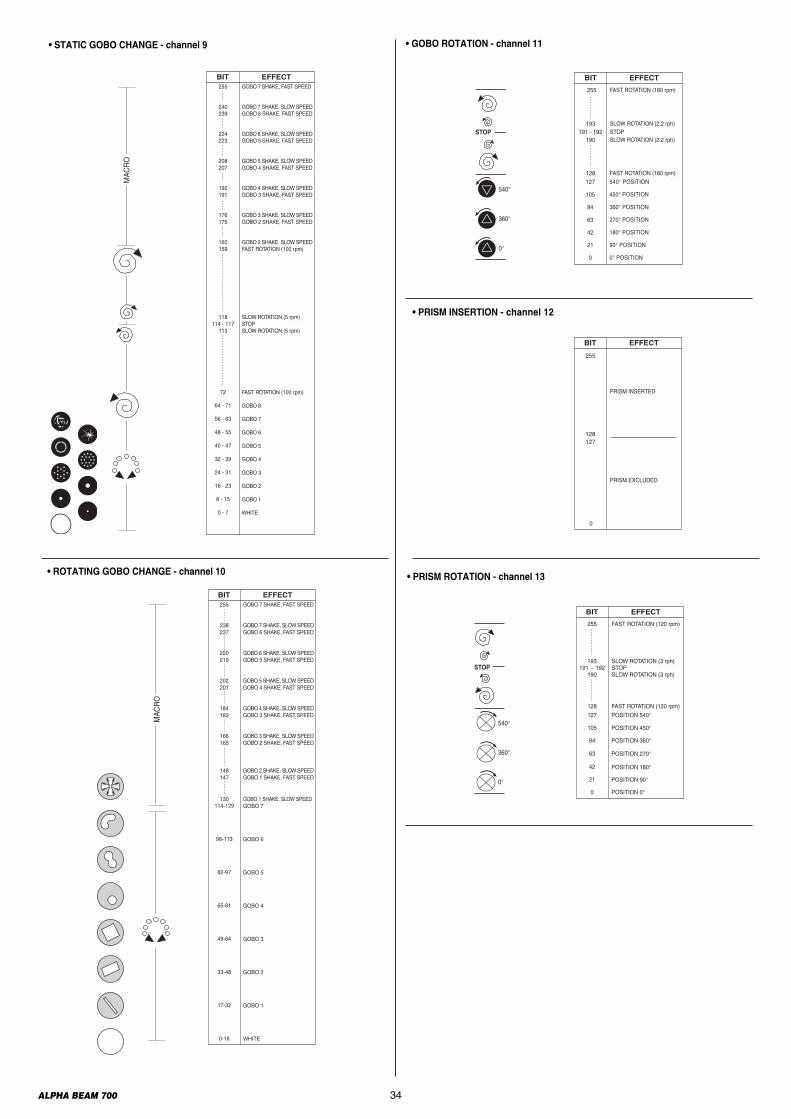
• PRISM ROTATION - channel 13
STOP
FAST ROTATION (120 rpm)
SLOW ROTATION (3 rph)
SLOW ROTATION (3 rph)
FAST ROTATION (120 rpm)
BIT EFFECT
191 - 192
255
193
190
128
STOP
540°
360°
0°
POSITION 540°127
POSITION 450°105
POSITION 360°84
POSITION 270°63
POSITION 180°42
0 POSITION 0°
POSITION 90°21
BIT EFFECT
128
PRISM EXCLUDED
0
255
PRISM INSERTED
127
• PRISM INSERTION - channel 12
0 0° POSITION
21 90° POSITION
42 180° POSITION
63 270° POSITION
84 360° POSITION
105 450° POSITION
127 540° POSITION
STOP
540°
360°
0°
255 FAST ROTATION (180 rpm)
193 SLOW ROTATION (2.2 rph) 191 - 192 STOP 190 SLOW ROTATION (2.2 rph)
BIT EFFECT
128 FAST ROTATION (180 rpm)
• GOBO ROTATION - channel 11• STATIC GOBO CHANGE - channel 9
GOBO 7 SHAKE, FAST SPEED
GOBO 7 SHAKE, SLOW SPEEDGOBO 6 SHAKE, FAST SPEED
GOBO 6 SHAKE, SLOW SPEEDGOBO 5 SHAKE, FAST SPEED
GOBO 5 SHAKE, SLOW SPEEDGOBO 4 SHAKE, FAST SPEED
GOBO 4 SHAKE, SLOW SPEEDGOBO 3 SHAKE, FAST SPEED
GOBO 3 SHAKE, SLOW SPEEDGOBO 2 SHAKE, FAST SPEED
GOBO 2 SHAKE, SLOW SPEEDFAST ROTATION (100 rpm)
SLOW ROTATION (5 rpm)STOPSLOW ROTATION (5 rpm)
FAST ROTATION (100 rpm)
GOBO 8
GOBO 7
GOBO 6
GOBO 5
GOBO 4
GOBO 3
GOBO 2
GOBO 1
WHITE
BIT EFFECT255
240239
224223
208207
192191
176175
160159
118114 - 117
113
72
64 - 71
56 - 63
48 - 55
40 - 47
32 - 39
24 - 31
16 - 23
8 - 15
0 - 7
MAC
RO
• ROTATING GOBO CHANGE - channel 10
130114-129
98-113
82-97
65-81
49-64
33-48
17-32
0-16
MAC
RO
GOBO 7 SHAKE, FAST SPEED
GOBO 7 SHAKE, SLOW SPEEDGOBO 6 SHAKE, FAST SPEED
GOBO 6 SHAKE, SLOW SPEEDGOBO 5 SHAKE, FAST SPEED
GOBO 5 SHAKE, SLOW SPEEDGOBO 4 SHAKE, FAST SPEED
GOBO 4 SHAKE, SLOW SPEEDGOBO 3 SHAKE, FAST SPEED
GOBO 3 SHAKE, SLOW SPEEDGOBO 2 SHAKE, FAST SPEED
GOBO 2 SHAKE, SLOW SPEEDGOBO 1 SHAKE, FAST SPEED
BIT EFFECT255
238237
220219
202201
184183
166165
148147
GOBO 1 SHAKE, SLOW SPEEDGOBO 7
GOBO 6
GOBO 5
GOBO 4
GOBO 3
GOBO 2
GOBO 1
WHITE
35ALPHA BEAM 700
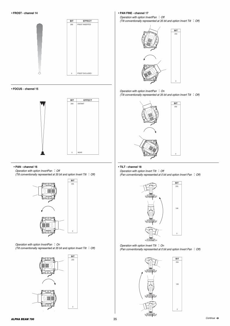
• FROST - channel 14
• FOCUS - channel 15
BIT EFFECT
255 DISTANT
0 NEAR
BIT EFFECT
255 FROST INSERTED
0 FROST EXCLUDED
• PAN FINE - channel 17Operation with option InvertPanGOff(Tilt conventionally represented at 35 bit and option Invert TiltGOff)
BIT
255
0
Operation with option InvertPanGOn(Tilt conventionally represented at 35 bit and option Invert TiltGOff)
BIT
255
0
Operation with option InvertPanGOn(Tilt conventionally represented at 35 bit and option Invert TiltGOff)
BIT
255
0
BIT
255
0
• PAN - channel 16Operation with option InvertPanGOff(Tilt conventionally represented at 35 bit and option Invert TiltGOff)
• TILT - channel 18Operation with option Invert TiltGOff(Pan conventionally represented at 0 bit and option Invert PanGOff)
BIT
255
128
0S E
TX
SEL
DMX
S E
TX
SEL
DMX
S E
TX
SEL
DMX
Operation with option Invert TiltGOn(Pan conventionally represented at 0 bit and option Invert PanGOff)
BIT
255
128
0
TX
SEL
DX
TX
SEL
D X
TX
SEL
DX
Continue ➔
36ALPHA BEAM 700
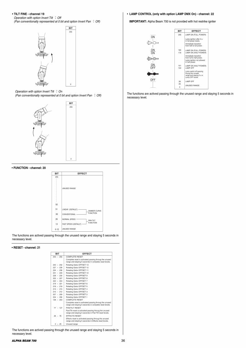
• LAMP CONTROL (only with option LAMP DMX On) - channel: 22
IMPORTANT: Alpha Beam 700 is not provided with hot restrike igniter
LAMP ON (FULL POWER)
LAMP ON (FULL POWER)
BIT EFFECT
255
180
0
101100 LAMP OFF
179
26 LAMP OFF25
UNUSED RANGE
Lamp ignition after 5 sin full power levels.
Lamp switch off passingthroug the unusedrange and staying 5 s inLamp OFF levels.
ON
ONON
OFF
ONOFF
LAMP ON (HALF POWER)
LAMP ON (HALF POWER)
Immediate transitionfrom full to half power.
Immediate transitionfrom half to full power.
Lamp ignition not allowedin half power.
• FUNCTION - channel: 20
BIT EFFECT255
52
51
39
26
13
0-12
LINEAR (DEFAULT)
UNUSED RANGE
UNUSED RANGE
CONVENTIONAL
NORMAL SPEED
FAST SPEED (DEFAULT)
DIMMER CURVEFUNCTION
PAN-TILTFUNCTION
• RESET - channel: 21
EFFECTBIT 243 – 255
240 – 242 237 – 239 234 – 236 231 – 233 228 – 230 225 – 227 222 – 224 219 – 221 216 – 218 213 – 215 210 – 212 207 – 209 204 – 206 128 – 203
77 – 127
26 – 76
0 – 25
COMPLETE RESETComplete reset is activated passing throug the unused range and staying 5 seconds in complete reset levels.
Rotating Gobo OFFSET 13Rotating Gobo OFFSET 12Rotating Gobo OFFSET 11Rotating Gobo OFFSET 10Rotating Gobo OFFSET 9Rotating Gobo OFFSET 8Rotating Gobo OFFSET 7Rotating Gobo OFFSET 6Rotating Gobo OFFSET 5Rotating Gobo OFFSET 4Rotating Gobo OFFSET 3Rotating Gobo OFFSET 2Rotating Gobo OFFSET 1COMPLETE RESETComplete reset is activated passing throug the unused range and staying 5 seconds in complete reset levels.
PAN/TILT RESETPan/Tilt reset is activated passing throug the unused range and staying 5 seconds in Pan/Tilt reset levels.
EFFECTS RESETEffects reset is activated passing throug the unused range and staying 5 seconds in Effects reset levels.
Unused range
• TILT FINE - channel 19Operation with option Invert TiltGOff(Pan conventionally represented at 0 bit and option Invert PanGOff)
BIT
255
0
S E
TX
SEL
DM X
S E
TX
SEL
DMX
Operation with option Invert TiltGOn(Pan conventionally represented at 0 bit and option Invert PanGOff)
BIT
255
0S E
TX
SEL
DMX
S E
TX
SEL
DMX
The functions are actived passing through the unused range and staying 5 seconds innecessary level.
The functions are actived passing through the unused range and staying 5 seconds innecessary level.
The functions are actived passing through the unused range and staying 5 seconds innecessary level.

37ALPHA BEAM 700
Timing Channel Channel function
23 Pan - Tilt time Pan - Tilt - (Pan fine - Tilt fine)
24 Colour time CMY - Colour wheel
25 Beam time Dimmer - Frost - Iris - Prism insertion
26 Gobo time Static Gobo - Rotating Gobo Change
BIT Seconds 0 Full 1 0.2 2 0.4 3 0.6 4 0.8 5 1 6 1.2 7 1.4 8 1.6 9 1.8 10 2 11 2.2 12 2.4 13 2.6 14 2.8 15 3 16 3.2 17 3.4 18 3.6 19 3.8 20 4 21 4.2 22 4.4 23 4.6 24 4.8 25 5 26 5.2 27 5.4 28 5.6 29 5.8 30 6 31 6.2 32 6.4 33 6.6 34 6.8 35 7 36 7.2 37 7.4 38 7.6 39 7.8 40 8 41 8.2 42 8.4
BIT Seconds 43 8.6 44 8.8 45 9 46 9.2 47 9.4 48 9.6 49 9.8 50 10 51 10.2 52 10.4 53 10.6 54
11 55 56
12 57 58
13 59 60 61 14 62 63
15 64 65 66 16 67 68
17 69 70 71 18 72 73
19 74 75 76 20 77 78 79 21 80 81
22 82 83 84 23 85
BIT Seconds 86
24 87 88 89 25 90 91
26 92 93 94 27 95 96
28 97 98 99 29 100 101 102 30 103 104
31 105 106 107 32 108 109
33 110 111 112 34 113 114
35 115 116 117 36 118 119
37 120 121 122 38 123 124 125 39 126 127
40 128
BIT Seconds 129 130 41 131 132
42 133 134 135 43 136 137
44 138 139 140 45 141 142
46 143 144 145 47 146 147
48 148 149 150 49 151 152 153 50 154 155
51 156 157 158 52 159 160
53 161 162 163 54 164 165
55 166 167 168 56 169 170
57 171
BIT Seconds 172 173 58 174 175 176 59 177 178
60 179 180 181 65 182 183
70 184 185 186 75 187 188
80 189 190 191 85 192 193
90 194 195 196 95 197 198
100 199 200 201 110 202 203 204 120 205 206
130 207 208 209 140 210 211
150 212 213 214 160 215
BIT Seconds 216
170 217 218 219 180 220 221
190 222 223 224 200 225 226 227 210 228 229
220 230 231 232 230 233 234
240 235 236 237 250 238 239
260 240 241 242 270 243 244
280 245 246 247 290 248 249
300 250 251 252
310 253 254 255
Follow cue Data
TIMING CHANNELS
TIME TABLE

CLAY PAKY S.p.A. - Via Pastrengo, 3/b - 24068 Seriate (BG) Italy - Tel. +39-035-654311- Fax +39-035-301876 - www.claypaky.it
Cod. 099101-EN - Rev.3 04/2015