instruction manual confined space rescue...confined space rescue portable fall arrest post model...
TRANSCRIPT

© 3M 2017FORM NO: 5902422REV: D
CONFINED SPACE RESCUEPortable Fall Arrest Post
Model Numbers:
8510816 8516691 8516692 8516693
8516997 8517266 8517362 8520041
8530071 8530155 8530614
DESCRIPTION
The ADVANCED PORTABLE FALL ARREST POST is a modular unit consisting of a 3 section tubular body, constructed of welded aluminum, featuring:
1. A head assembly equipped with 3 independent swivel tie-off rings.
2. Various accessories to address different situations.
3. Adjusting screws for vertical leveling of the Fall Arrest Post when installed on inclined surfaces.
4. Featuring adjustable height option from 33.0 in. (84 cm) to 57.5 in. (146 cm).
INSTRUCTION MANUAL
This manual is intended to meet the Manufacturer’s Instructions and should be used as part of an employee training program as required by OSHA

2
Figure 1 - Portable Fall Arrest Post
Section 1
Section 2
Section 3
6
5
Optional Anchor Post Davit Arm Assembly
4
8
9
12
7
10
11
13
3
12
14
15
Post Items1 Uni-Anchor Base Plate 2 Base Plate Tabs3 Adjuster Screw4 3/4 inch Pin5 Sleeve6 Tri-Screws7 Section 1 Pin8 Section 2 Pin9 Section 3 Pin10 Swivel Tie Off Rings (3)11 Davit Anchor Ring12 Extension Sleeve13 Anchor Post Extension (Accessory)14 Anchor Point Eye15 Carrying Handle
16
17
18
19
20
23
25
22
26
21
16 3/8” Pin Assembly 17 Davit Anchor Eye 18 Cable Assembly 19 U-Bracket 20 Carabineer 21 Davit Arm Sleeve 22 Davit Arm Receiver Tube 23 Head Pin Assembly 24 Clamp Screw Knobs 25 Davit Head Assembly 26 Mounting Brackets
24
1.0 APPLICATION
1.1 PURPOSE: DBI-SALA’s Portable Fall Arrest Post is designed as an anchorage connector for a person(s) working at a height to provide protection against fall hazards. Various accessories address a variety of fall arrest requirements, as well as confi ned space entry/retrieval and rescue needs.
1.2 LIMITATIONS: The following application limitations must be recognized and considered before using this product:A. CAPACITY: The Portable Fall Arrest Post is designed to be used as an anchorage connector for up
to three persons. The maximum combined weight (including clothing, tools and equipment) of each person is 310 lbs (141 kg). Use of various accessories may reduce the number of workers that may be anchored.
B. APPLICATION RESTRICTIONS:
IMPORTANT: Always install the Portable Fall Arrest Post to the following strength requirements to avoid potential incompatability with different models:
Moment Requirement Vertical Load Requirement
190,000 in-lbs (20.8 kN-m) 4,200 lbs force (18.7 kN)
* Install to this strength requirement whenever possible to avoid potential imcompatability with different models
• A maximum of three (3) persons may be tied off to the Portable Fall Arrest Post at any one time. Use of various accessories may reduce the number of persons that may be anchored. Consult product specification sheets for all components of any system, and be aware of any restrictions before using the equipment.

3
• The Portable Fall Arrest Post must be in a vertical position any time it is being used as a fall arrest anchor point.
• Installed Post and accessories must be 72 inches (183 cm) or less from any edge where a fall may occur.
• Fall arrest equipment (retractable devices, shock absorbers, etc.) must conform with the current ANSI and OSHA standards.
• The Portable Fall Arrest Post must only be used with accessories supplied or approved by Capital Safety.
• The HLL must be installed using the chart in Figure 6; giving due consideration to strength limitations at various positions.
• The Portable Fall Arrest Post must be used with a tie-back in Horizontal Lifeline applications at any extended height. Failure to follow this instruction may result in serious injury or death.
• Each installation must be approved to local standards by a qualified engineer.
2.0 SET UP AND USE OF THE PORTABLE FALL ARREST SYSTEM
2.1 SET UP:
The DBI-SALA Portable Fall Arrest Post is designed for use with a variety of portable and permanent bases. Consult the appropriate section of this manual or separate manuals when setting up or installing any DBI-SALA Portable Fall Arrest Post Bases.
Step 1: Before setting up for any work at heights, fall arrest, or confi ned space entry be sure that you have all equipment required to safely carry out the work to be performed, and to meet all applicable standards and regulations for your area.
Step 2: Set-up or locate the Portable Fall Arrest System Base intended for use in the application according to the instructions in the applicable section of this manual. Ensure that the base is structurally sound and free of any corrosion or contamination which may affect the insertion of the connecting pin or the structural integrity of the base. Regulations governing Fall Protection, Confi ned-Space Entry/ Retrieval and Rescue Procedures vary with jurisdiction. It is the responsibility of the owner and/or user of this equipment to be aware of applicable regulations and ensure that equipment selected for each job complies with these requirements. Refer to the appropriate section of this or any other applicable manuals for specifi c information on the installation and use of the type of base you are using prior to using the system.
Step 3: As shown in Figure 2, insert the Portable Fall Arrest Post between the base plate tabs (2) and visually align the ¾ in. holes as shown in Figure 3.
Secure the Post by inserting the ¾ in. (19 mm) pin (4) Figure 3 through the base plate tabs Figure 2 (2) and sleeve (5) Figure 2. Make sure the pin fully engages both the base plate tabs (2) and the entire Post to lock the Post fi rmly in place.
Step 4: Extend the post as shown in Figure 4 A by loosening tri-screw (6) and removing Section 1 pin (7) from Section 1. Lift Section 2 and align the pin holes, secure Section 2 in Section 1 by fully engaging Section 1 pin (7). The post should look like Figure 4 B.
Loosen tri-screw (6) Figure 4 B and lift Section 3. Align pin holes with Section 2, Figure 4 B and secure the Post Section 3 by using Section 2 pin (8). The post should look like Figure 5. Hand tighten both tri-screws Figure 4 (6).
Step 5: The Portable Fall Arrest Post must be in a vertical position at all times, as shown in Figure 5, when it is being used as a fall arrest anchor point. Depending on the type of base you are using, the Post may be leveled by using the adjuster screws (3) Figure 5, the Uni-Anchor Plate (1) Figure 5, or a combination of these. The adjuster screws are alternately loosened and tightened to level the Post.
Step 6: Install any accessories (eg. Anchor Post Extension) that installs in the extension sleeve (10) at the top of the Portable Fall Arrest Post. Refer to the applicable section of this or other applicable accessory manuals for any accessories being used with this system.
Step 7: Depending on the nature of the entry and the standards and regulations governing Confi ned
Figure 2 - Post and Base Assembly
2
5

4
Space Entry/Retrieval and Rescue requirements in your area, a Personal Fall Arrest System (PFAS) connected to the entrant may be required. It is the responsibility of the operator to be aware of these requirements and follow them. Always wear a full body harness when attached to a PFAS.
Step 8: Once the system is set-up inspect all components, fasteners, and other parts for wear, damage, corrosion, looseness, or any other condition that may reduce the integrity of the system. Components which are worn, damaged, corroded, or loose, must be tagged, marked with “DO NOT USE” or like wording and prevented from being used until repaired or replaced as required.
Step 9: Following all instructions contained in the manufacturer’s instructions for each PFAS component or any other devices being used, the appropriate section of this manual or other manuals for any DBI-SALA Accessories being used, and all applicable standards or regulations governing Fall Protection, Confi ned Space Entry/ Retrieval and Rescue for your area proceed with the work.
Figure 5 - Post ExtensionFigure 3 - Post Base
4
Figure 4 - Post Extension
A B
Extend
6
7
8
3
1
2.2 USING THE PORTABLE FALL ARREST POST FOR HORIZONTAL LIFELINE (HLL) APPLICATIONS:The DBI-SALA Portable Fall Arrest Post can be used for most temporary Horizontal Lifelines (HLL) applications, therefore using existing mounting bases as the temporary base for HLL applications. See Figure 5 for location of HLL Anchor Ring
2.2.1 SETTING UP THE PORTABLE FALL ARREST POST FOR HLL USE:When using this post for HLL applications, it is critical to know when to use a tie-back and when not to use a tie-back to support the HLL loads. Refer to the chart in Figure 6 to confi rm what loads can be sustained by the Portable Fall Arrest Post unsupported by a tieback. Follow all labels carefully when setting up for HLL applications and refer to the chart when unsure of load ratings.

5
Figure 6 - HLL Chart Positions and Ratings
54.50 in138.4 cm
43.00 in109.2 cm
41.50 in105.4 cm
30.50 in77.5 cm
H.L.L.57.20 in145.4 cm
H.L.L.46.00 in116.8 cm
H.L.L.44.00 in111.8 cm
H.L.L.32.75 in83.2 cm
Horizontal Lifeline (H.L.L.) Positions and Ratings Ultimate Strength Position Without Tie-Back Position Height 4 3250 Lbs (14.5 kN) 57.25 in. (145.4 cm) 3 4000 Lbs (17.7 kN) 46.00 in. (116.8 cm) 2 4000 Lbs (17.7 kN) 44.00 in. (111.8 cm) 1 5700 Lbs (25.0 kN) 32.75 in. (83.2 cm)
Tie-back Anchorage Connectors must be approved by Capital Safety and all tie-back anchor points must be approved by a qualified engineer before use.
Position 4
Position 3Position 2
Position 1
Step 1: Follow set-up instructions in section 2.1 of this manual.
Step 2: The post can be used without the installation of a tie-back as shown in Figure 7 A. Refer to the “HLL Chart Positions & Ratings”, Figure 6 for maximum ratings without the use of a tie-back.
Step 3: Using the mast with the second and/or third stage erected (Positions 4, 3 & 2) and HLL load ratings that exceed the load rating shown in the chart, Figure 6, must have tie-backs installed as shown in Figure 7 B.
Step 4: Using the davit arm with a HLL requires the third section, (Positions 4 & 3) of the mast to be erected to install the davit arm sleeve. Refer to the chart to verify tie-back use.
Refer to section 2.2.5 of this manual for Davit Arm set-up.
Step 5: Install HLL using the carabineer supplied with the HLL assembly to the HLL Anchor Ring provided on the mast as shown in Figure 7 C. Follow all manufactures instruction carefully when installing a HLL.
If you require a tie-back, install the tieback using the opposite eye across from the installed HLL on the HLL Anchor Ring.
Tie-back anchors must be designed and approved by the manufacturer (Capital Safety) and the structure mounting requirements approved by a qualifi ed engineer. Call Capital Safety to purchase the suitable tie-back for the application.
The DBI-SALA Portable Fall Arrest Post with HLL Anchor Ring can also be used as an intermediate for a HLL to spanning across longer distances.

6
Figure 7 - HLL Use
HLL HLL
HLL Tie-back
A B
C
HLL
Davit Anchor Ring
HLL Tie-back or Intermediate Anchor
2.2.2 MOUNTING BASES
Uni-Anchor Plates: Uni-Anchor Plates are designed to be permanently welded to existing structures in locations of frequent work, or where use of portable base is impractical. These mounting plates are compatible with all DBI-SALA Portable Fall Arrest Posts and Accessories. Uni-Anchor Plates permanently address Portable Fall Arrest Post mounting base requirements for steel structures.
Installing Uni-Anchor Plates: Specifi c installation instructions are beyond the scope of this product operator’s manual. Consult DBI-SALA Safety Systems Product Specifi cation Sheets for detailed information on welding procedures, mounting requirements and application restrictions.
Installing Portable Mounting Bases: Specifi c installation instructions are beyond the scope of this product operator’s manual. Consult Instruction 8516997 (I-Beam Clamp Base) for detailed information on mounting procedures, mounting requirements and application restrictions.
Set-up of the Portable Fall Arrest Post: Install and level the Portable Fall Arrest Post as outlined in Section 2.1.
2.2.3 PORTABLE FALL ARREST POST ACCESSORIES
The DBI-SALA Portable Fall Arrest Post may be equipped with a variety of accessories to meet additional confi ned space entry/retrieval, rescue, or fall protection requirements. Use of these accessories may affect the rating and load carrying capacities of the Portable Fall Arrest Post. Be aware of any limitations imposed on the system by the use of various accessories, and follow any restrictions given on the various product specifi cation sheets, warning labels, this manual and/or related manuals.
Shock absorbers and retractable devices must be installed, maintained and used according to the manufacturer’s instructions.
Figure 8 - Uni-Anchor Plate
7
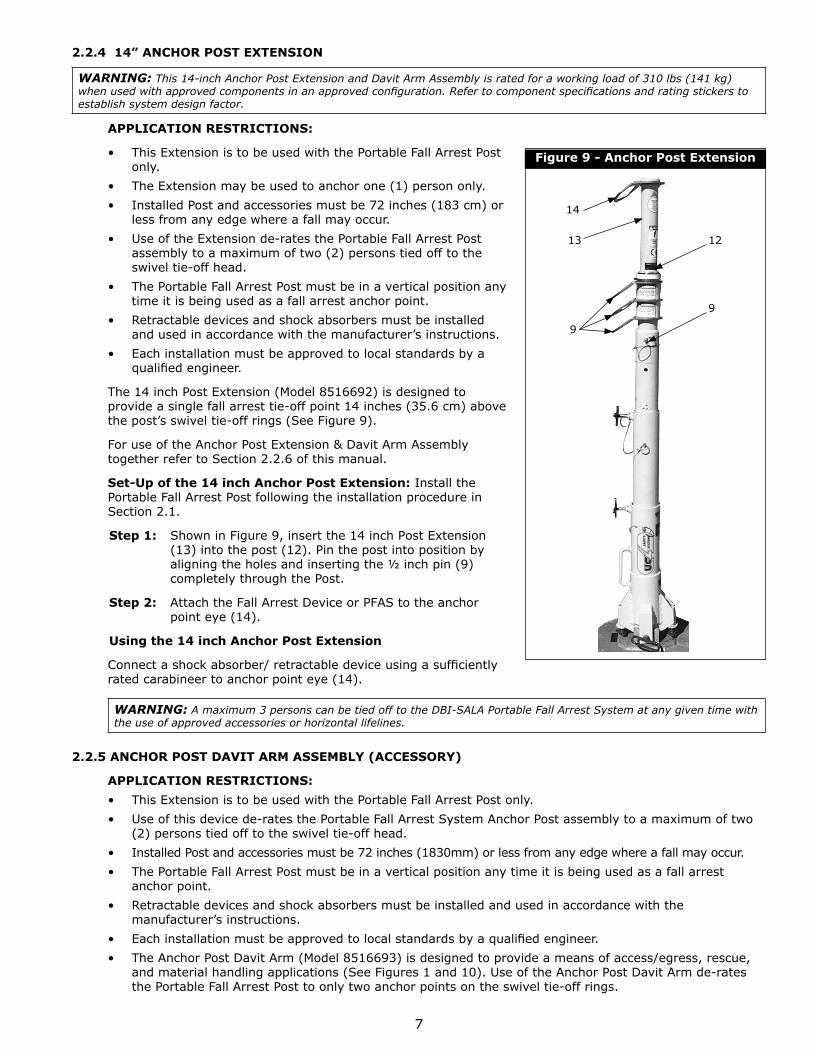
2.2.4 14” ANCHOR POST EXTENSION
WARNING: This 14-inch Anchor Post Extension and Davit Arm Assembly is rated for a working load of 310 lbs (141 kg) when used with approved components in an approved confi guration. Refer to component specifi cations and rating stickers to establish system design factor.
APPLICATION RESTRICTIONS:
• This Extension is to be used with the Portable Fall Arrest Post only.
• The Extension may be used to anchor one (1) person only.
• Installed Post and accessories must be 72 inches (183 cm) or less from any edge where a fall may occur.
• Use of the Extension de-rates the Portable Fall Arrest Post assembly to a maximum of two (2) persons tied off to the swivel tie-off head.
• The Portable Fall Arrest Post must be in a vertical position any time it is being used as a fall arrest anchor point.
• Retractable devices and shock absorbers must be installed and used in accordance with the manufacturer’s instructions.
• Each installation must be approved to local standards by a qualifi ed engineer.
The 14 inch Post Extension (Model 8516692) is designed to provide a single fall arrest tie-off point 14 inches (35.6 cm) above the post’s swivel tie-off rings (See Figure 9).
For use of the Anchor Post Extension & Davit Arm Assembly together refer to Section 2.2.6 of this manual.
Set-Up of the 14 inch Anchor Post Extension: Install the Portable Fall Arrest Post following the installation procedure in Section 2.1.
Step 1: Shown in Figure 9, insert the 14 inch Post Extension (13) into the post (12). Pin the post into position by aligning the holes and inserting the ½ inch pin (9) completely through the Post.
Step 2: Attach the Fall Arrest Device or PFAS to the anchor point eye (14).
Using the 14 inch Anchor Post Extension
Connect a shock absorber/ retractable device using a suffi ciently rated carabineer to anchor point eye (14).
WARNING: A maximum 3 persons can be tied off to the DBI-SALA Portable Fall Arrest System at any given time with the use of approved accessories or horizontal lifelines.
2.2.5 ANCHOR POST DAVIT ARM ASSEMBLY (ACCESSORY)
APPLICATION RESTRICTIONS:
• This Extension is to be used with the Portable Fall Arrest Post only.
• Use of this device de-rates the Portable Fall Arrest System Anchor Post assembly to a maximum of two (2) persons tied off to the swivel tie-off head.
• Installed Post and accessories must be 72 inches (1830mm) or less from any edge where a fall may occur.
• The Portable Fall Arrest Post must be in a vertical position any time it is being used as a fall arrest anchor point.
• Retractable devices and shock absorbers must be installed and used in accordance with the manufacturer’s instructions.
• Each installation must be approved to local standards by a qualifi ed engineer.
• The Anchor Post Davit Arm (Model 8516693) is designed to provide a means of access/egress, rescue, and material handling applications (See Figures 1 and 10). Use of the Anchor Post Davit Arm de-rates the Portable Fall Arrest Post to only two anchor points on the swivel tie-off rings.
Figure 9 - Anchor Post Extension
13 12
9
14
9

8
Set-Up of the Anchor Post Davit Arm Assembly: Install the Anchor Post/ Davit Arm Assembly starting with and following the system assembly procedure in Section 2.1.
Step 1: Shown in Figure 11, clamp the Davit Arm Sleeve (21) over Section 3 of the Portable Fall Arrest Post.
Step 2: Install and secure the Davit Arm Sleeve (21) by closing the sleeve around section 3 and hand tightening the clamp knob screws (24) as shown in Figure 11.
Step 3: Insert the Davit Head Assembly (23) and align one of the three 3/8 in pin holes in the Davit Arm Receiver Tube. Using the pin (16) secure the Davit Arm into position and to vary the offset.
Step 4: Shown in Figure 11, secure the cable assembly (18) to the Portable Fall Arrest Post using the carabineer (20) provided and connecting it to the Davit Arm Anchor Eye (17).
2.2.6 USING THE DAVIT ARM ASSEMBLY The Davit Arm Assembly is designed with adjustable offset and 360 degree rotation. This Davit Arm Assembly allows the combined use of an entry/ retrieval winch and a self-retracting lifeline (SRL).
Step 1: Adjust the offset by pulling the pin assembly (16) and selecting the one of three holes offered in the Davit Arm receiver tube (22) as shown in Figure 12.
2.3 RESCUE
The Davit arm can be rotated 360 degrees in a rescue/retrieval situation so an injured worker can be moved to a safe environment.
The Portable Fall Arrest Post must be used in a vertical position at all times to effectively rotate the Davit Arm. The Portable Fall Arrest Post may be used as a fall arrest anchor point during a rescue scenario. Alternative anchor points for fall protection use should be identifi ed and planned for use during a rescue scenario.
Mounting Brackets for Winch and SRL
The mounting brackets are for use with the Davit Arm Assembly. Winches and SRL’s must have a suitable working load.
Set-up of the Mounting Brackets
The mounting brackets are bolted onto the Davit Arm Assembly when shipped from the manufacturer. The brackets are arranged to most common Winch/ SRL confi guration. If these brackets need to be repositioned to suit your application, remove the two bolts securing the bracket to the Davit Arm Receiver Tube (9) shown in Figure 13, reposition to other bracket mount location and replace bolts and tighten.
WARNING: The Adaptor Brackets for your winch or SRL must be offset to the side that the crank handle is on to eliminate interference between the crank handle and the Davit Arm Assembly and the mounting brackets. Not following these instructions can impair retrieval capabilities that can cause serious injury or death.
Using the Mounting Brackets
Install and use the winch and/or SRL according to manufacturer’s instructions.
Proper operation and maintenance of the winch and/or SRL are critical to the safe usage of your DBI-SALA Portable Fall Arrest Post.
Winch and SRL Operation
Shown with the accessories in Section 2.2.5 is the DBI-SALA “Basic” Man-Rated Winch available for use with the DBI-SALA Portable Fall Arrest Post. The winch is necessary for worker positioning and rescue situations when using the Davit Arm Assembly. The winch is available in a variety of lifeline capacities, and lifelines are available in a variety of lengths and materials. Winches and SRL’s must used and maintained in accordance with the manufacturer’s instructions, please refer to the instruction manual provided with your winch or SRL.
Figure 10 - Anchor Post Davit Arm
16
17
18
19
2023
25
22
26
21
8
24

9
3.0 INSPECTION
3.1 FREQUENCY: Before each use visually inspect per steps listed in Section 3.2 and 3.3.
3.2 INSPECTION STEPS:
Step 1. Inspect the Portable Fall Arrest Post for physical damage. Look carefully for any signs of cracks, dents or deformities in the metal. Make certain the post, brackets and other components are not deformed in any way and that they pivot correctly.
Step 2. Inspect the Portable Fall Arrest Post for signs of excessive corrosion.
Step 3. Ensure the condition of the mounting surface will support the anchor plate loads. An anchor plate to a deteriorated surface should not be used.
Step 4. Ensure the anchor plate is securely attached to the mounting surface. See section 2.1.
Step 5. Inspect each system component or subsystem (i.e. self retracting lifeline, full body harness, etc.) per associated manufacturer’s instructions.
Step 6. Record the inspection date and results on the ‘Inspection and Maintenance Log’.
3.3 If inspection reveals an defective condition, remove unit from service immediately and destroy, or contact a factory authorized service center for repair.
IMPORTANT: Only Capital Safety or parties authorized in writing may make repairs to this equipment.
Figure 11 - Anchor Post Set Up
21
24
18
20
17
Figure 12 - Using the Davit Arm
22
16
Figure 13 - Mounting Brackets
Bracket bolts Bracket mount locations

10
4.0 MAINTENANCE - SERVICING - STORAGE
4.1 Clean the Portable Fall Arrest Post with a mild soap detergent solution. Excessive build-up of dirt, tar, etc. may prevent the system from working properly. If you have any questions concerning the condition of your Portable Fall Arrest Post or have any doubt about putting it into service, contact Capital Safety immediately. Refer to manufacturer’s instruction for maintenance, servicing, and storage procedures of subsystem components.
4.2 Additional maintenance and servicing procedures (i.e. replacement parts) must be completed by a factory authorized service center. Authorization must be in writing.
5.0 SPECIFICATIONS
MATERIALS:
MATERIALS AND FINISH: Zinc plated or powder coated, 6061-T6 aluminum anodized, steel anchor plateHardware: Grade 5/Grade 8 zinc plated.
CAPACITY: The maximum working load for this product is three persons with a combined weight of 310 lbs. (141 kg) per person.
STATIC LOAD CAPACITY: Strength of system maintains a minimum safety factor of 2 as required by OSHA when according to this user instruction manual (reference OSHA 1926.502 and 1910.66).
WEIGHT: Post 38 lbs. (17.5 kg); 14 inch extension 5 lbs. (2.2 kg); rescue davit 20.5 lbs. (9.3 kg)
SIZE (COLLAPSED): 33 inch (840mm) height
SIZE (EXTENDED): 57.5 inch (1460mm) height
INSPECTION AND MAINTENANCE LOG
SERIAL NUMBER:
MODEL NUMBER:
DATE PURCHASED: DATE OF FIRST USE:
INSPECTION DATE INSPECTION ITEMS NOTED
CORRECTIVE ACTION MAINTENANCE PERFORMED
Approved By:
Approved By:
Approved By:
Approved By:
Approved By:
Approved By:
Approved By:
Approved By:
Approved By:

11
6.0 LABELING
The following labels must be securely attached and full legible:
A
B
FE
D
G
A
C
A
B
C
A
A
A
A
D E
This man-rated system isdesigned for a maximum
1 2 3 4person(s) user capacity in
accordance with manufacturer’sinstructions.
WARNING
Pt# 20099
FG
WARNING
This component is rated for a workingload of 310 lb. (141 kg) when usedwith approved components in anapproved configuration. Refer tocomponent specifications and ratingstickers to establish system designfactor.
Pt# 16970
USA3833 SALA Way Red Wing, MN 55066-5005 Toll Free: 800.328.6146Phone: 651.388.8282Fax: [email protected]
BrazilRua Anne Frank, 2621Boqueirão Curitiba PR81650-020BrazilPhone: [email protected]
MexicoCalle Norte 35, 895-ECol. Industrial VallejoC.P. 02300 AzcapotzalcoMexico D.F.Phone: (55) [email protected]
ColombiaCompañía Latinoamericana de Seguridad S.A.S.Carrera 106 #15-25 Interior 105 Manzana 15Zona Franca - Bogotá, ColombiaPhone: 57 1 [email protected]
Canada260 Export Boulevard Mississauga, ON L5S 1Y9 Phone: 905.795.9333 Toll-Free: 800.387.7484 Fax: 888.387.7484 [email protected]
EMEA (Europe, Middle East, Africa)EMEA Headquarters:Le Broc CenterZ.I. 1re Avenue - BP1506511 Carros Le Broc CedexFrancePhone: + 33 04 97 10 00 10Fax: + 33 04 93 08 79 [email protected]
Australia & New Zealand95 Derby StreetSilverwaterSydney NSW 2128AustraliaPhone: +(61) 2 8753 7600Toll-Free : 1800 245 002 (AUS)Toll-Free : 0800 212 505 (NZ) Fax: +(61) 2 8753 7603 [email protected]
AsiaSingapore:1 Yishun Avenue 7Singapore 768923Phone: +65-6450 8888Fax: +65-6552 [email protected]
Shanghai:19/F, L’Avenue, No.99 Xian Xia RdShanghai 200051, P R China Phone: +86 21 62539050Fax: +86 21 [email protected]
Korea:3M Koread Ltd20F, 82, Uisadang-daero,Yeongdeungpo-gu, SeoulPhone: +82-80-033-4114Fax: [email protected]
Japan:3M Japan Ltd6-7-29, Kitashinagawa, Shinagawa-ku, TokyoPhone: +81-570-011-321Fax: [email protected]
WEBSITE:3M.com/FallProtection
I S O9001 FM534873
EU DECLARATION OF CONFORMITY:3M.com/FallProtection/DOC
U.S. PRODUCT WARRANTY, LIMITED REMEDY AND LIMITATION OF LIABILITY
WARRANTY: THE FOLLOWING IS MADE IN LIEU OF ALL WARRANTIES OR CONDITIONS, EXPRESS OR IMPLIED, INCLUDING THE IMPLIED WARRANTIES OR CONDITIONS OF MERCHANTABILITY OR FITNESS FOR A PARTICULAR PURPOSE. Unless otherwise provided by applicable law, 3M fall protection products are warranted against factory defects in workmanship and materials for a period of one year from the date of installation or fi rst use by the original owner.LIMITED REMEDY: Upon written notice to 3M, 3M will repair or replace any product determined by 3M to have a factory defect in workmanship or materials. 3M reserves the right to require product be returned to its facility for evaluation of warranty claims. This warranty does not cover product damage due to wear, abuse, misuse, damage in transit, failure to maintain the product or other damage beyond 3M’s control. 3M will be the sole judge of product condition and warranty options.This warranty applies only to the original purchaser and is the only warranty applicable to 3M’s fall protection products. Please contact 3M’s customer service department at 800-328-6146 or via email at [email protected] for assistance.LIMITATION OF LIABILITY: TO THE EXTENT PERMITTED BY APPLICABLE LAW, 3M IS NOT LIABLE FOR ANY INDIRECT, INCIDENTAL, SPECIAL OR CONSEQUENTIAL DAMAGES INCLUDING, BUT NOT LIMITED TO LOSS OF PROFITS, IN ANY WAY RELATED TO THE PRODUCTS REGARDLESS OF THE LEGAL THEORY ASSERTED.