instruction manual - quantrol · each series 100/150 chemical feeder has been tested to meet...
TRANSCRIPT
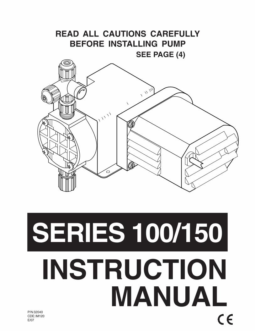
READ ALL CAUTIONS CAREFULLYBEFORE INSTALLING PUMP
P/N 32040CDE: IM120E/07
SERIES 100/150
MANUALINSTRUCTION
SEE PAGE (4)
2 of 16
SAFETY INSTRUCTIONSREAD ALL INSTRUCTIONS PRIOR TO USE
*** : Secure chemicals & metering pumps, making them inaccessible to children & pets.
*** DO NOT PUMP FLAMMABLE LIQUIDS.
*** Do not cut the plug or ground lug off the electrical cord. Consult a licensed electrician for proper installationor replacement.
** : Always wear protective clothing, including gloves and safety glasses, when working on or nearchemical metering pumps.
** Inspect tubing regularly for cracking or deterioration and replace as necessary. (Always wear protectiveclothing and safety glasses when inspecting tubing.)
** Use CAUTION to keep fingers away from rotatiing parts.
** If pump is exposed to direct sunlight, use a U.V. resistant tubing.
** Follow directions and warnings provided from the chemical manufacturer. The user is responsible fordetermining the chemical compatibility with the chemical feed pump.
** Make sure the voltage on the pump name tag matches the installation voltage. If pump fails to start, check linevoltage.
** Consult with local health officials and/or qualified water conditioning specialists when treating potable water.
** Always depressurize system prior to installation or disconnecting the metering pump tubing.
** If injection point is lower than the chemical tank and pump, install an anti-siphon valve.
** DO NOT MODIFY PUMP. This poses a potentially dangerous situation and will void the warranty.
* : All pumps are factory tested with water. Remove tubing and thoroughly dry if the chemicalbeing pumped will react with water (for example sulfuric acid).
* Hand tighten plastic connections (Do not use wrench).
* Consult licensed plumber and electrician before installation to conform to local codes.
* NOTE: For accurate volume output, pump must be calibrated under all operating conditions.
TABLE OF CONTENTSPage
SAFETY INSTRUCTIONS ............................................................................................................................... 2
INTRODUCTION .............................................................................................................................................. 3
PRECAUTIONS FOR OPERATION ................................................................................................................. 4
INSTALLATION, PIPING AND WIRING ............................................................................................................ 5
MAINTENANCE ............................................................................................................................................ 10
SERVICE AND REPAIRS ............................................................................................................................. 11
TROUBLESHOOTING ................................................................................................................................... 13
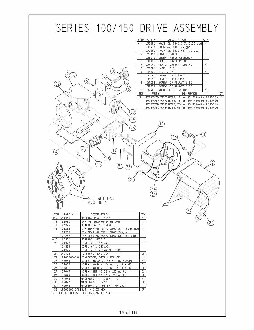
PARTS LIST (EXPLODED PUMP ASSEMBLY) ............................................................................................ 15
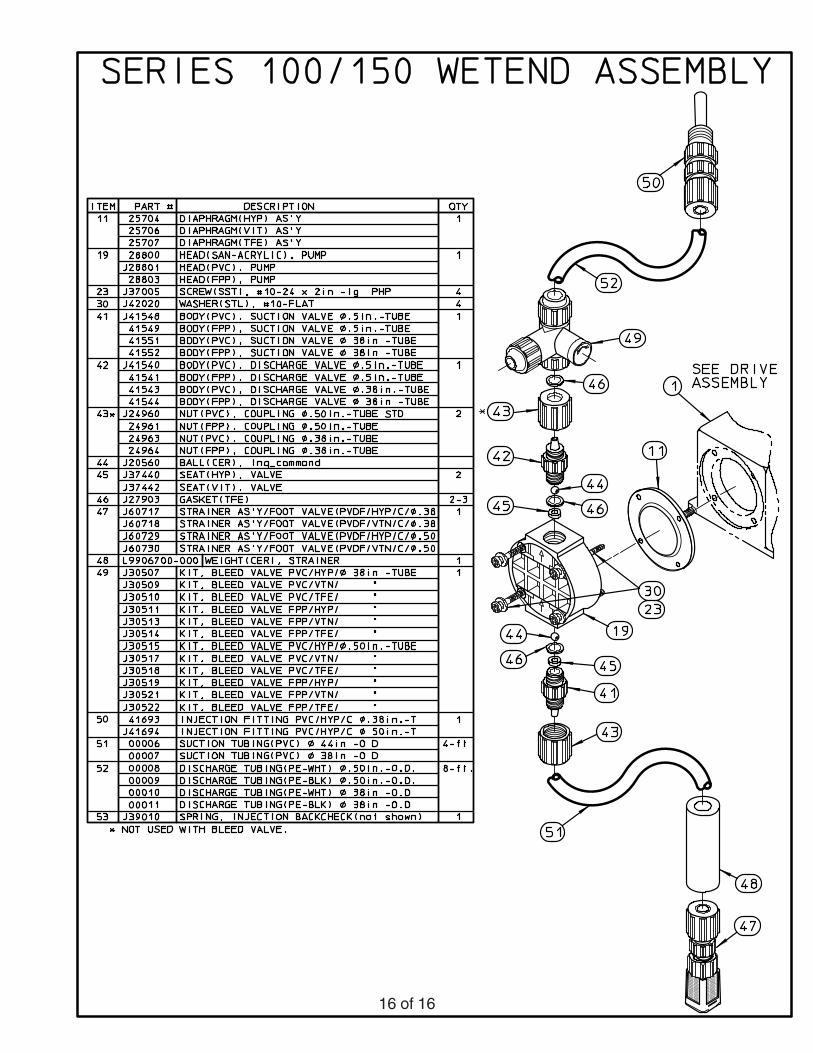
REPLACEMENT KITS (EXPLODED WET END ASSEMBLY) ....................................................................... 16
INTRODUCTION
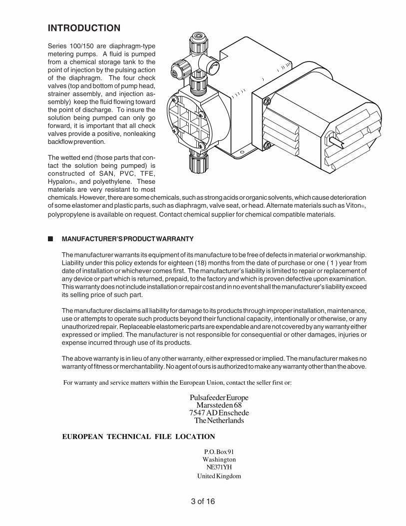
Series 100/150 are diaphragm-typemetering pumps. A fluid is pumpedfrom a chemical storage tank to thepoint of injection by the pulsing actionof the diaphragm. The four checkvalves (top and bottom of pump head,strainer assembly, and injection as-sembly) keep the fluid flowing towardthe point of discharge. To insure thesolution being pumped can only goforward, it is important that all checkvalves provide a positive, nonleakingbackflow prevention.
The wetted end (those parts that con-tact the solution being pumped) isconstructed of SAN, PVC, TFE,Hypalon®, and polyethylene. Thesematerials are very resistant to mostchemicals. However, there are some chemicals, such as strong acids or organic solvents, which cause deteriorationof some elastomer and plastic parts, such as diaphragm, valve seat, or head. Alternate materials such as Viton®,polypropylene is available on request. Contact chemical supplier for chemical compatible materials.
MMMMM MANUFACTURER’S PRODUCT WARRANTY
The manufacturer warrants its equipment of its manufacture to be free of defects in material or workmanship.Liability under this policy extends for eighteen (18) months from the date of purchase or one ( 1 ) year fromdate of installation or whichever comes first. The manufacturer’s liability is limited to repair or replacement ofany device or part which is returned, prepaid, to the factory and which is proven defective upon examination.This warranty does not include installation or repair cost and in no event shall the manufacturer’s liability exceedits selling price of such part.
The manufacturer disclaims all liability for damage to its products through improper installation, maintenance,use or attempts to operate such products beyond their functional capacity, intentionally or otherwise, or anyunauthorized repair. Replaceable elastomeric parts are expendable and are not covered by any warranty eitherexpressed or implied. The manufacturer is not responsible for consequential or other damages, injuries orexpense incurred through use of its products.
The above warranty is in lieu of any other warranty, either expressed or implied. The manufacturer makes nowarranty of fitness or merchantability. No agent of ours is authorized to make any warranty other than the above.
For warranty and service matters within the European Union, contact the seller first or:
Pulsafeeder EuropeMarssteden 68
7547 AD EnschedeThe Netherlands
EUROPEAN TECHNICAL FILE LOCATION
P.O. Box 91Washington
NE371YHUnited Kingdom
3 of 16

4 of 16
PRECAUTIONS FOR OPERATION
Each Series 100/150 chemical feeder has been tested to meet prescribed specifications and certain safetystandards. However, a few precautionary notes should be adhered to at all times. THOROUGHLY READ ALLCAUTIONS PRIOR TO INSTALLING METERING PUMP.
1. Protective fitting caps must be removed prior to installing tubing onto fitting assemblies.
2. Chemicals used may be dangerous and should be used carefully and according to warnings on the label.Follow the directions given with each type of chemical. Do not assume chemicals are the same becausethey look alike. Always store chemicals in a safe location away from children and others. We cannotbe responsible for the misuse of chemicals being fed by the pump.
3. Always wear protective clothing (protective gloves and safety glasses) when working on or near chemicalmetering pumps.
4. Tampering with electrical devices can be potentially hazardous. Always place chemicals and feederinstallation well out of the reach of children and others.
5. Be careful to check that the voltage of the installation matches the voltage indicated on the specificationlabel. Each pump is equipped with a three prong plug. Whether plugging into a receptacle or wiring intoa system, always be sure the feeder is grounded. If receptacle is utilized, to disconnect, do not pull wirebut grip the plug with fingers and pull out.
6. Never repair or move the metering pump while operating. Always disconnect electrical current. Beforehandling the pump always allow sufficient time for the motor housing to cool off. Handling the pump toosoon after shutdown may cause hand burns. For safety __ use protective gloves.
7. All pumps are pretested with water before shipment. Remove head and dry thoroughly if you are pumpinga material that will react with water, (i.e. sulfuric acid). Valve seats, ball checks, gaskets, and diaphragmshould also be dried. Before placing feeder into service, extreme care should be taken to follow thisprocedure.
8. Arrows on the pump head and injection fitting indicate chemical flow. When properly installed, thesearrows should be pointing upward.
9. When metering hazardous material DO NOT use plastic tubing. Strictly use proper rigid pipe. Consultsupplier for special adaptors.
10. Pump is NOT to be used to handle or meter flammable liquids or materials.
11. Standard white polyethylene discharge tubing is not recommended for installations exposed to directsunlight. Consult supplier for special black polyethylene tubing.
12. Manufacturer will not be held responsible for improper installation of pumps, or local plumbing conducted.All cautions are to be read thoroughly prior to hook-up and plumbing. For all installations a professionalplumber should be consulted. Always adhere to local plumbing codes and requirements.
13. Note the maximum pressure rating of the metering pump. When used with pressurized systems, alwaysbe sure the pressure of the system does not exceed maximum pressure rating listed on the specificationlabel.
14. Be sure to depressurize system prior to hook-up or disconnection of metering pump.
INSTALLATION, PIPING AND WIRING
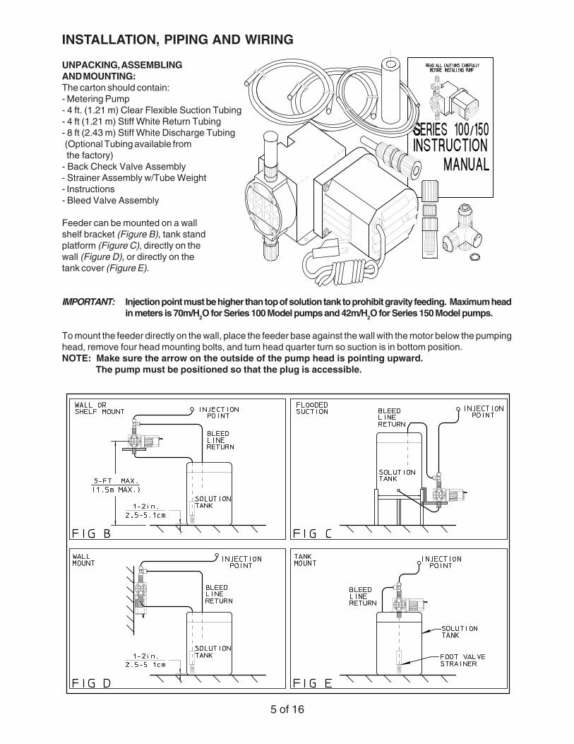
UNPACKING, ASSEMBLINGAND MOUNTING:The carton should contain:- Metering Pump- 4 ft. (1.21 m) Clear Flexible Suction Tubing- 4 ft (1.21 m) Stiff White Return Tubing- 8 ft (2.43 m) Stiff White Discharge Tubing (Optional Tubing available from the factory)- Back Check Valve Assembly- Strainer Assembly w/Tube Weight- Instructions- Bleed Valve Assembly
Feeder can be mounted on a wallshelf bracket (Figure B), tank standplatform (Figure C), directly on thewall (Figure D), or directly on thetank cover (Figure E).
IMPORTANT: Injection point must be higher than top of solution tank to prohibit gravity feeding. Maximum headin meters is 70m/H2O for Series 100 Model pumps and 42m/H2O for Series 150 Model pumps.
To mount the feeder directly on the wall, place the feeder base against the wall with the motor below the pumpinghead, remove four head mounting bolts, and turn head quarter turn so suction is in bottom position.NOTE: Make sure the arrow on the outside of the pump head is pointing upward.
The pump must be positioned so that the plug is accessible.
5 of 16

Flooded suction mounting (installing feeder at thebase of tank on a platform) is the most trouble freetype of installation. (Tank stands and platformsare available for all size feeders and tanks). Thepump is secured on the platform, then the clearsuction tubing is attached to a bulkhead fittingassembly and the suction valve housing on thepump head. Since the suction tubing is alwaysfilled with solution, priming is accomplished muchmore quickly and the chance of losing prime on aninstallation, where the feeder is used only a fewhours a day, is greatly reduced.
The feeder comes with a bleed valve assemblythat attaches to the discharge valve in the pumphead. The bleed valve allows you to manuallyprime the feeder and depressurize the dischargeline without disconnecting the feeder from thetubing connections.
NOTE: To operate without bleed valve, replace bleed valve (item #49) and 0.38 in. (0.96 cm) -tubing size dischargevalve housing (item # 42) with a 0.50 in. (1.27 cm) -tubing size discharge valve housing (item #42) and coupling nut(item #43). See page 16 (Wet End Assembly). Items #42 and #43 are available from factory.
Remove protective caps and assemble tubing and fittings to the feeder (Fig. G).
: Do not force fittings __ Do not use additional sealants,HAND TIGHTEN ONLY. such as pipe tape, on fittings.
: If water is used todissolve solid chemicals or create adilute solution, the chemical tanksshould be manually filled or an approvedmeans must be used to prevent a crossconnection between the chemical tankcontents and the potable water line.Check local plumbing regulations.
CHEMICAL INJECTION:
Chemical injection into an open tank:The discharge tubing can be placed inan open tank with or without the injectionvalve assembly. Each feeder is shippedwith a spring loaded back check injectionvalve. This assists in a positive seal onthe discharge side of the pump headpreventing back flow.
Pumps carrying the 'NSF' or the 'ETLSanitation' (tested to NSF standard-50)approval are listed for swimming pools,spas, and hot tubs, and when propermaterials are selected, are capable ofhandling but not limited to the followingchemical solutions.
121/2% sodium hypochlorite2% calcium hypochlorite
12% aluminum sulfate10% hydrochloric acid10% sodium hydroxide5% sodium carbonate
6 of 16

INSTALLATION INTO A WELLPUMP SYSTEM:
Make sure the voltage of thefeeder matches the voltage ofthe well pump. Install the injec-tion fitting into a tee which is in-stalled into the water line going tothe pressure tank. The end of theinjection check valve should be inthe main stream of the water line. Atypical installation is shown in Fig-ure H. For installation of pumpfor operating swimming pools,pump is to be supplied by anisolating transformer or thru an"RCD" (residual current device).
NOTE: It is recommended toinstall the injection assembly in avertical position on the bottomside of the water line (Figure J).This will insure proper sealing ofthe injection assembly check valveand prevent a back flow into thefeeder's discharge line. Be surearrow on injection fitting is pointingupward.
DOWN-THE-WELL INSTALLATION:
Often it is desirable to provide chemical feed near theintake of the well pump for additional retention timeand mixing of the chemicals. An additional length ofdischarge tubing will be required for this installation.Secure the end of the discharge tubing to the pumpcylinder, drop pipe, or foot valve and lower it into thewell. An anti-siphon valve must be installed onsystems such as this where the discharge is lowerthan the feeder and the chemical storage tank.Failure to install anti-siphon valve may allowsiphoning to occur.
ANTI-SIPHON VALVE: (optional)
Under any installation condition where the possibility of siphoning or suction may occur on the discharge side ofthe pump, install an anti-siphon valve on the discharge side of the feeder. The anti-siphon valve is not part of thestandard package. This item can be furnished by your dealer at extra cost.
PRESSURE RELIEF VALVE: (optional)
All Series 100/150 chemical pumps are rated to pump against a line pressure of 100 PSI ( 7 BAR). If the line pressureon an installation could fluctuate above 100 PSI ( 7 BAR), install a pressure relief valve on the discharge side of thepump head. Once the pressure reaches a certain level, the pre-set relief valve will return the solution being pumpedback to the solution tank. This will prevent motor burnout or diaphragm rupture. The relief valve is not part of thestandard package. This item can be furnished by your dealer at extra cost. Read relief valve instructions carefullybefore installing.
7 of 16

8 of 16
HAND TIGHTEN FITTINGS:
When connecting tubing to suction and discharge fittings, the coupling nuts should be tightened hand tight only.Excessive tightening can cause cracks in pump head.
POINT OF INJECTION:
Pipe corrosion can result if dillution at the injection point does not occur rapidly. This problem is easily preventedby observing this simple rule: install injection fitting so that the end is in the flow stream of the line being treated.NOTE: Extended injection assemblies are available for large water lines. Consult your dealer.
COMMON ERRORS IN THE INJECTION OF CHEMICALS:
Do not insert the injection fitting into a pipe stub in the tee. A full strength solution will often cause corrosion or scalein the pipe stub when it is not in the flowing stream (Figure J). The maximum lift of the chemical feeder is five feet.Be sure not to exceed this height. It is very important that the arrow on the fittings and the pump head pointvertically upward in order to prevent backflow. Arrows indicate the proper flow of the chemical.
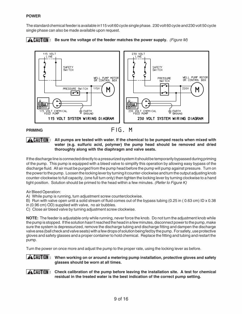
POWER
The standard chemical feeder is available in115 volt 60 cycle single phase. 230 volt 60 cycle and 230 volt 50 cyclesingle phase can also be made available upon request.
: Be sure the voltage of the feeder matches the power supply. (Figure M)
PRIMING
: All pumps are tested with water. If the chemical to be pumped reacts when mixed withwater (e.g. sulfuric acid, polymer) the pump head should be removed and driedthoroughly along with the diaphragm and valve seats.
If the discharge line is connected directly to a pressurized system it should be temporarily bypassed during primingof the pump. This pump is equipped with a bleed valve to simplify this operation by allowing easy bypass of thedischarge fluid. All air must be purged from the pump head before the pump will pump against pressure. Turn onthe power to the pump. Loosen the locking lever by turning it counter-clockwise and turn the output adjusting knobcounter-clockwise to full capacity, (one full turn only) then tighten the locking lever by turning clockwise to a handtight position. Solution should be primed to the head within a few minutes. (Refer to Figure K)
Air Bleed Operation:A) While pump is running, turn adjustment screw counterclockwise.B) Run with valve open until a solid stream of fluid comes out of the bypass tubing (0.25 in ( 0.63 cm) ID x 0.38in (0.96 cm) OD) supplied with valve, no air bubbles.C) Close air bleed valve by turning adjustment screw clockwise.
NOTE: The feeder is adjustable only while running, never force the knob. Do not turn the adjustment knob whilethe pump is stopped. If the solution hasn't reached the head in a few minutes, disconnect power to the pump, makesure the system is depressurized, remove the discharge tubing and discharge fitting and dampen the dischargevalve area (ball check and valve seats) with a few drops of solution being fed by the pump. For safety, use protectivegloves and safety glasses and a proper container to hold chemical. Replace the fitting and tubing and restart thepump.
Turn the power on once more and adjust the pump to the proper rate, using the locking lever as before.
: When working on or around a metering pump installation, protective gloves and safetyglasses should be worn at all times.
: Check calibration of the pump before leaving the installation site. A test for chemicalresidual in the treated water is the best indication of the correct pump setting.
9 of 16

MAINTENANCE
SCALE: GASKETS AND CHECK VALVES
When checking the metering pump or providing routine maintenance, replace all valve seats or ball checks if anyof them show any wear or deterioration. (Valve seats should be checked approximately every 4-6 months dependingupon the application.) Repeated deterioration of valve seats and other rubber or plastic parts within a few monthsperiod usually indicates another material should be used for the defective part. Contact your supplier or see theparts list for parts affected for possible alternate materials..
OUTSIDE INSTALLATION:
In many areas where freezing conditions are not a problem it is common to install a metering pump outside.Adequate protection should be provided to keep the pump from being exposed to direct sunlight or rain. Any simplecovering adequately ventilated will afford the necessary protection from weather. NOTE: When discharge tubingis exposed to direct sunlight, black polyethylene tubing should be used in lieu of the stiff white translucent tubingsupplied with each pump.
SOLUTION TANK:
Check the solution tank for settling of chemicals. If there is sludge on the bottom of the solution tank, clean thestrainer, the foot valve, and the solution tank. Installing the foot valve a few inches above the bottom of the tank willprevent future clogging. NOTE: If the chemical being pumped regularly precipitates out of solution or doesnot dissolve easily or completely ( calcium hydroxide), mixers are readily available in different motorconfigurations and mountings.
OUTPUT ADJUSTING KNOB:
Sometimes the output adjusting knob can move on its shaft and cause a false output indication. This can happenif the knob set-screw slips or if the unit is disassembled for any reason. The unit can be reset to "0" as follows:
1. Remove the dial stop.
2. With the pump running, loosen the locking lever and turn the adjusting knob counter-clockwise until it is "loose"to touch.
3. SLOWLY rescrew the knob clockwise, using very light finger pressure. It will soon start to advance in pulsesas the internal cam comes in and out of contact.
4. When light finger pressure will no longer allow movement of the knob between cam contacts, grasp the knobsecurely and tighten the locking lever (turning clockwise) making sure that the knob does not move. To checkfor zero point, turn on pump. There should be no liquid coming out of discharge fitting.
5. Replace dial stop.
6. If the pointer is not at "0", loosen the set-screw onthe knob (use a .078 in Hex key), and turn pointer to"0", then retighten the set-screw while holding theknob in place.
7. A setting of "0" will now give zero utput. One fullrevolution of the knob counter clockwise will givemaximum output. The knob should never be turnedmore than one full revolution.
10 of 16
SERVICING AND REPAIRS
REPLACEMENT OF PUMP HEAD ASSEMBLY OR DIAPHRAGM:
: Before performing any repairs on Series 100/150 chemical feeders, be sure to disconnectall electrical connections and relieve pressure from suction/discharge tubing.
The Series 100/150 feeder was designed so that servicing can be quick and simple. Proper part replacementprocedures are described below.
NOTE: Use protective gloves and safety glasses when working on or around chemical feeder.
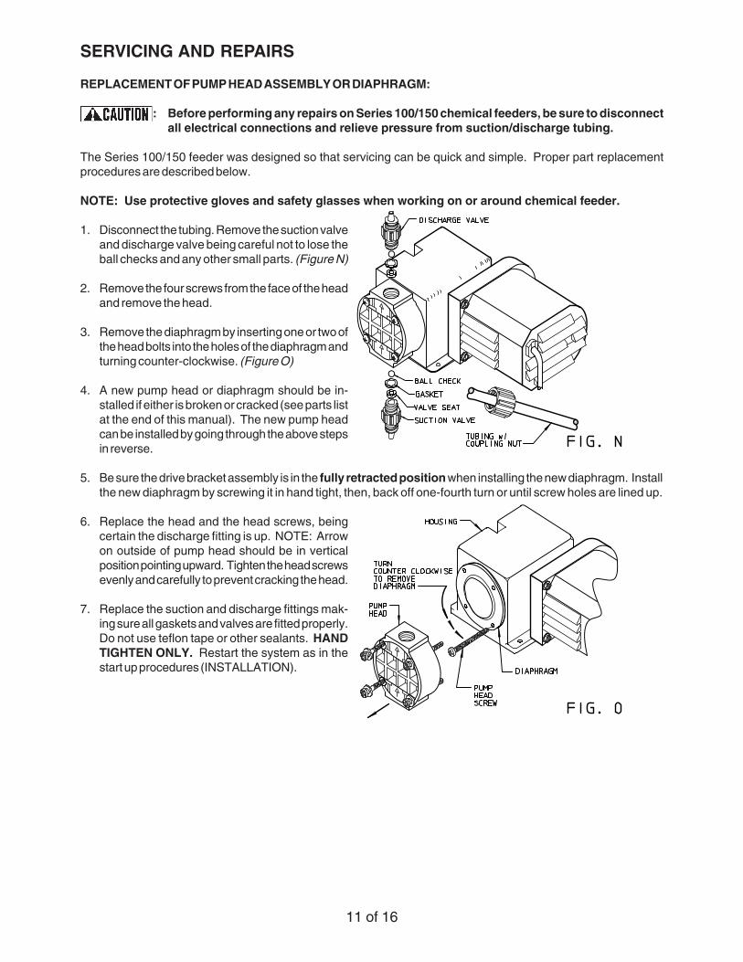
1. Disconnect the tubing. Remove the suction valveand discharge valve being careful not to lose theball checks and any other small parts. (Figure N)
2. Remove the four screws from the face of the headand remove the head.
3. Remove the diaphragm by inserting one or two ofthe head bolts into the holes of the diaphragm andturning counter-clockwise. (Figure O)
4. A new pump head or diaphragm should be in-stalled if either is broken or cracked (see parts listat the end of this manual). The new pump headcan be installed by going through the above stepsin reverse.
5. Be sure the drive bracket assembly is in the fully retracted position when installing the new diaphragm. Installthe new diaphragm by screwing it in hand tight, then, back off one-fourth turn or until screw holes are lined up.
6. Replace the head and the head screws, beingcertain the discharge fitting is up. NOTE: Arrowon outside of pump head should be in verticalposition pointing upward. Tighten the head screwsevenly and carefully to prevent cracking the head.
7. Replace the suction and discharge fittings mak-ing sure all gaskets and valves are fitted properly.Do not use teflon tape or other sealants. HANDTIGHTEN ONLY. Restart the system as in thestart up procedures (INSTALLATION).
11 of 16
12 of 16
BALL CHECKS AND VALVE SEAT REPLACEMENT:
The following procedure is the same for any of the four valves.
: Make sure all electrical connections are disconnected and pressure valves off.
NOTE: Use protective gloves and safety glasses while replacing parts.
1. Unscrew compression nut and remove tubing.
2. Unscrew check valve body from pump head, foot valve, or injection fitting.
3. Remove all seats, ball checks, and gaskets and replace.
4. Replace the check valve body so fitting makes contact with the gasket and the pump head, foot valve or injectionfitting, whichever the case may be. HAND TIGHTEN FITTINGS ONLY. Do not use pipe tape or other sealantson these threads.
5. Re-install the tubing and tighten coupling nut HAND TIGHT.
6. Restart the system as in the INSTALLATION PROCEDURES.
13 of 16
TROUBLESHOOTING
PROBLEM PROBABLE CAUSE REMEDY
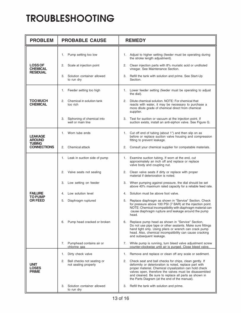
1. Pump setting too low 1. Adjust to higher setting (feeder must be operating duringthe stroke length adjustment).
LOSS OF 2. Scale at injection point 2. Clean injection parts with 8% muriatic acid or undilutedCHEMICAL vinegar. See Maintenance Section.RESIDUAL
3. Solution container allowed 3. Refill the tank with solution and prime. See Start-Upto run dry Section.
1. Feeder setting too high 1. Lower feeder setting (feeder must be operating to adjustthe dial).
TOO MUCH 2. Chemical in solution tank 2. Dilute chemical solution. NOTE: For chemical thatCHEMICAL too rich reacts with water, it may be necessary to purchase a
more dilute grade of chemical direct from chemicalsupplier.
3. Siphoning of chemical into 3. Test for suction or vacuum at the injection point. Ifwell or main line suction exists, install an anti-siphon valve. See Figure G.
1. Worn tube ends 1. Cut off end of tubing (about 1") and then slip on asLEAKAGE before or replace suction valve housing and compressionAROUND fitting to prevent leakage.TUBINGCONNECTIONS 2. Chemical attack 2. Consult your chemical supplier for compatable materials.
1. Leak in suction side of pump 1. Examine suction tubing. If worn at the end, cutapproximately an inch off and replace or replacevalve body and coupling nut.
2. Valve seats not sealing 2. Clean valve seats if dirty or replace with propermaterial if deterioration is noted.
3. Low setting on feeder 3. When pumping against pressure, the dial should be setabove 40% maximum rated capacity for a reliable feed rate.
FAILURE 4. Low solution level 4. Solution must be above foot valve.TO PUMPOR FEED 5. Diaphragm ruptured 5. Replace diaphragm as shown in "Service" Section. Check
for pressure above 100 PSI (7 BAR) at the injection point.NOTE: Chemical incompatibility with diaphragm material can
cause diaphragm rupture and leakage around the pump head.
6. Pump head cracked or broken 6. Replace pump head as shown in "Service" Section,Do not use pipe tape or other sealants. Make sure fittingshand tight only. Using pliers or wrench can crack pumphead. Also, chemical incompatibility can cause crackingand subsequent leakage.
7. Pumphead contains air or 7. While pump is running, turn bleed valve adjustment screwchlorine gas counter-clockwise until air is purged. Close bleed valve.
1. Dirty check valve 1. Remove and replace or clean off any scale or sediment.
2. Ball checks not seating or 2. Check seat and ball checks for chips, clean gently. IfUNIT not sealing properly deformity or deterioration is noted, replace part withLOSES proper material. Chemical crysalization can hold checkPRIME valves open, therefore the valves must be disassembled
and cleaned. Be sure to replace all parts as shown inthe Parts Diagram (at the end of the manual).
3. Solution container allowed 3. Refill the tank with solution and prime.to run dry

14 of 16
PROBLEM PROBABLE CAUSE REMEDY
1. Loose fittings 1. All fittings can be hand tightened to prevent leakage.Clean off chemicals which have spilled on feeder.
LEAKAGEAT FITTING 2. Broken or twisted gasket 2. Check gaskets and replace if broken or damaged.
3. Chemical attack 3. Consult your chemical supplier for compatablematerials.
1. Too much pressure at 1. Open bleed valve and circulate fluid until all air is purgeddischarge from pump head assembly. Close bleed valve.
FEEDERWILL NOT 2. Check valves not sealing 2. Disassemble, loosen, clean and check for deteriorationPRIME or swelling. Reassemble and wet the valve assembly,
then prime. See INSTALLATION Section.
3. Output dials not set at 3. Always prime pump with output dial set at maximummaximum rated capacity.
ANTI-SIPHON 1. Scale or particles have 4. Remove, clean and reassemble, being careful not toVALVE plugged diaphragm wrinkle the diaphragm. Check sequence and positionMALFUNC- of parts to be sure reassembly is correct.TION
2. Ruptured valves 5. Consult your distributor for replacement.
PUMP 1. Pumping against excessive 1. Test pressure to determine if it exceeds feederMOTOR pressure specifications. If so, consult your distributor.STALLS
2. Low voltage to feeder 2. Make sure voltage of power source matches the voltageon the feeder specifications label. If not transformersare available.
MOTOR 1. Low voltage. 1. Power supply voltage should match voltage on feederRUNNING specification label.VERY HOT
2. If using a stepdown transformer, 2. Check the transformer to be sure it has at leastit may be undersized for the feeder 100 watts capacity.
15 of 16
16 of 16