instruction manual electrostatic controller e-sc24 -ex · pdf fileinstruction manual...
TRANSCRIPT

Instruction manual
■ Electrostatic Controller E-spraySeries
E-SC24 -EX series E-SC24L-EX series
KEMA 0344 EN50050 BVS 06 ATEX E 049
E-SC24-EX series is only for E-MW100 series. E-SC24L-EX series is only for E-MW50 series. To be installed only safe area
This instruction manual contains IMPORTANT WARNINGS, CAUTIONS and
instructions for safe operation. Before operation, be sure to read this
instruction manual thoroughly and understand the equipment so that you can use
it safely and effectively for a long time.
Keep this booklet in an appropriate place for immediate reference.

Important information - Safety Precautions This electrostatic controller is exclusively used for electrostatic painting. Be sure to read and
understand this instruction manual. Both the supervisor and operator shall be fully knowledgeable about the requirements stated
within this instruction manual, including important warnings, cautions and proper method of operation.
Wrong operation (mishandling) can cause serious bodily injury, death, fire or explosion.
This electrostatic controller is used along with related electrostatic spray guns (E-MW100, [for
E-SC24-EX] / E-MW50 [for E-SC24L-EX]): options) and paint pump (e.g. DPS-90), etc. When using related equipment, also read instruction manuals for those products.
Keep this booklet in an appropriate place for immediate reference.
1. About safety Pay special attention to items which are shown by below marks and symbols.
Symbols and marks have the following meanings.
Indication of warnings and cautions
WARNING Indicates a potentially hazardous situation which, if not avoided, will result in serious injury or loss of life.
CAUTION Indicates a potentially hazardous situation which, if not avoided, may result in minor or moderate injury or property damage.
Examples of warnings and cautions
Indicates [You must be careful]. We will explain briefly in or near the symbol. (The example on the left is [Be careful about electric shock]).
Indicates [You must not do]. We will explain briefly in or near the symbol. (The example on the left is [Do not touch]).
Indicates [You must do]. We will explain briefly in or near the symbol. (The example on the left is [Be sure to ground it]).
We shall not be responsible for any injury or damage caused by disregard of warnings, cautions or instructions.
Indicates notes which we ask you to observe. They are helpful to fully achieve performance and functions of the equipment. Important
①

Warnings and cautions for safe operation
WARNING
Fire and Explosion
Avoidance of fire and explosion at painting site
Never install it at a site with flammable goods or bring flammable goods like lighters. Paints and organic solvents are flammable, able to cause fire. Never use the following Halogenated Hydrocarbon solvents which can chemically react with spray gun parts (aluminum parts) etc., crack and melt them. Improper solvents: methyl chloride, dichloromethane, 1,2-dichloroethane, carbon
tetrachloride, trichloroethylene, 1.1.1.-trichloroethane (Be sure that all fluids and solvents are compatible with gun parts. We are ready to supply a material list used in the gun on request.)
Avoidance of fire caused by grounding failure
Be sure to keep hanger or conveyor clean without paint stuck on it and keep them conductive. Incomplete grounding, dirty hanger or conveyor cannot conduct electricity, and static electricity accumulates, resulting in fire accident by spark discharge.
Store paint and solvent in a metallic container which is grounded. Poorly grounded conductor can accumulate static electricity, causing fire accident by spark discharge. If you are forced to place conductive goods such as fluid container and fluid supply pump within 3m from the gun, be sure to ground them without fail.
Securely ground electrostatic controller (A class grounding: less than 10Ω). As you ground the electrostatic spray gun by contacting electrostatic controller through low voltage cable, incomplete grounding can accumulate static electricity on spray gun, causing fire accident by spark discharge or bodily injury by electric shock.
A class grounding
○(Good!) ×(Bad!)
Be sure to contact metallic points by makingcontact points knife-edged or sharp-pointed.
②

Avoidance of fire by ignition of paints and solvents
Be sure to turn off electric source of electrostatic controller (E-SC24-EX / E-SC24L-EX series) before cleaning inside of fluid passages. As paints and solvents are flammable and have low flash points, they can catch fire if there is spark discharge in and around painting site.
Spray distance between work-piece and painting equipment must be over 10cm. If the distance is less than 10cm, spark discharge can occur and paint can catch fire.
Never use lacquer paints. Lacquer paints have low flash points and can catch fire.
Do not cover electrostatic spray gun with anti-dust sheet. Static electricity accumulated on sheet can discharge and solvent gas can catch fire.
Wrong operation
Avoidance of wrong use
Never point toward human or animal during spraying. If done, it can cause inflammation of eye or skin and bodily injury. Never use gas other than compressed air. If done, it can cause fire or poisoning accident. Never use at higher than max. operating pressure (refer to specifications on page 2). Tip of fluid needle has a sharp point. Do not touch the tip of fluid needle during maintenance for the protection of the human body.
Avoidance of wrong operation
Before inspecting, cleaning, disassembling or assembling electrostatic spray gun, be sure to turn off electric source of electrostatic controller (E-SC24-EX / E-SC24L-EX series), interlocked equipment and equipment and fully release air and fluid pressure in the following procedure. If not, it can cause bodily injury by wrong operation.
Job 1) Turn off electric source of electrostatic controller (E-SC24-EX / E-SC24L-EX series). Job 2) Stop supply of compressed air, paint and solvent to spray equipment.
Job 3) Turn electrostatic spray gun downwards, pull trigger, operate fluid needle and fully
release air pressure and fluid pressure.
③

Bodily protection
Protection from solvents, air and fluid pressure
Use spray booth and do the painting job in a well-ventilated place. Painting and cleaning jobs in a poorly ventilated site can cause organic solvent poisoning and ignition. Always wear protective tool such as protective goggles and mask. If not, cleaning liquid can touch eyes and skin, causing inflammation. If you feel something wrong with eyes or skin, immediately consult with a doctor. We recommend you to wear earplugs for your safety. Noise level can reach over 85dB(A) depending on operating and working conditions. Be sure to turn off electric source of electrostatic controller or multi-gun control system and release fluid and air pressure before cleaning, disassembling or doing maintenance job or during stoppage of job. If not, remaining pressure can cause bodily injury through wrong operation and spattering of cleaning liquid. Be sure to follow [Avoidance of wrong operation ] on page ③ in order to turn off electric source, and release air and fluid pressure.
Protection from static electricity
Be sure to wear electrostatic shoes(resistance figure 105~10
8Ω、JIS T 8103) and anti-charge
working clothes(JIS T 8118). If not, static electricity can accumulate on human body and cause bodily accidents by electric shock.
Operators must not wear metallic things such as watch or key holders during operation. If done, static electricity can accumulate on them and you will get an electric shock. If you wear glasses with metallic frame and approach
the gun, you can get an electric shock. Before approaching spray equipment, turn off electric source of electrostatic controller or multi-gun control system.
Operator must always hold electrostatic spray gun with bare hand or glove having a large hole at palm position. As human body is grounded through the handle of electrostatic spray gun, static electricity can accumulate on human body and cause bodily harm by electric shock if operator holds the gun handle with normal glove.
When you turn off main electric source switch in order to stop the gun operation in an emergency, it takes about 5 seconds till the electric potential of electrostatic spray gun goes down to a safe level. Don’t try to touch the pin electrode at tip of gun during that period.
Anti-charge workingclothes
Electrostatic shoes
Protection of human body If operators pull the trigger many times during operation, it may cause repetitive strain injury. Be sure to take a rest if you feel tired.
④

Others
Never use altered parts or other than genuine parts when parts are damaged or worn out. If done, it can cause failure of the gun, accidents or bodily injury.
Be sure to install a fire extinguisher at painting site.
Make sure that the equipment has stopped before you enter the working range of other painting equipment (robot, reciprocator, etc.). If not, moving robot or reciprocator can injure you.
Never use for food or chemicals. If done, erosion in paint passages can cause accidents, and foreign matter can enter.
extinguisher
⑤

Contents
for a Operator
1. Specifications ············································P. 3 2. Names and functions of each section ·····P. 4 3. Operation····················································P. 5 4. Safeguards ·················································P. 7 5. Daily maintenance and inspection···········P. 10 6. Problems and remedies (troubleshooting)P. 11
for a Supervisor
7. Specifications ············································P. 13
8. Check the products ···································P. 13
9. Names and functions of each section ·····P. 14
10. Setup of electrostatic controller ···············P. 16
11. Operation·····················································P. 21
12. Safeguards··················································P. 24
13. Daily maintenance and inspection ···········P. 27
14. Parts List ···················································P. 28
15. Problems and remedies (troubleshooting) ···········P. 29
The operator and the supervisor of this electrostatic controller must fully read and understand from P.2 to P.9 (for a Operator).
Only the supervisor and / or other equally qualified personnel, having fully read and understood the contents of this instruction manual, can take care of matters related to P.10 to P.26
Note:

【for a operator】
Electrostatic Controller E-SC24 -EX series E-SC24L-EX series
Instruction manual
< for a operator>
‐2‐ 【for a operator】
【for a operator】
1 Specifications
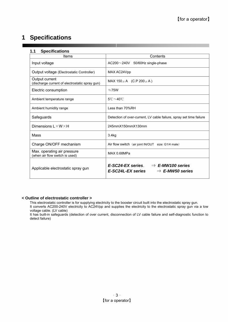
1.1 Specifications Items Contents
Input voltage AC200~240V 50/60Hz single-phase
Output voltage (Electrostatic Controller) MAX AC24Vpp
Output current (discharge current of electrostatic spray gun) MAX 150μA (C.P 200μA )
Electric consumption ≒75W
Ambient temperature range 5℃~40℃
Ambient humidity range Less than 70%RH
Safeguards Detection of over-current, LV cable failure, spray set time failure
Dimensions L×W×H 245mmX150mmX130mm
Mass 3.4kg
Charge ON/OFF mechanism Air flow switch(air joint IN/OUT size: G1/4 male)
Max. operating air pressure (when air flow switch is used) MAX 0.68MPa
Applicable electrostatic spray gun
E-SC24-EX series. ⇒ E-MW100 series E-SC24L-EX series ⇒ E-MW50 series
< Outline of electrostatic controller >
This electrostatic controller is for supplying electricity to the booster circuit built into the electrostatic spray gun. It converts AC200-240V electricity to AC24Vpp and supplies the electricity to the electrostatic spray gun via a low voltage cable. (LV cable) It has built-in safeguards (detection of over current, disconnection of LV cable failure and self-diagnostic function to detect failure)
‐3‐ 【for a operator】
【for a operator】
2 Names and functions of each section
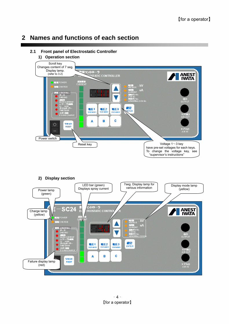
2.1 Front panel of Electrostatic Controller 1) Operation section
Voltage 1~3 key have pre-set voltages for each keys.To change the voltage key, see
“supervisor’s instructions”
Power switch
Reset key
Scroll key Changes content of 7 seg.
Display lamp. (refer to 3.2)
2) Display section
Power lamp (green)
Charge lamp (yellow)
LED bar (green) Displays spray current
7seg. Display lamp for various information
Display mode lamp (yellow)
Failure display lamp (red)
‐4‐ 【for a operator】

【for a operator】
3 Operation
3.1 Normal operation
WARNING
(1) When charging electrically, be sure to ground all surrounding metallic things. If not it can cause fire
or injury of electric shock.
CAUTION
(1) During charging (when high voltage is generated), do not put electrostatic spray gun within about 50cm of Electrostatic Controller. If done, Electrostatic Controller can fail if it sparks, as Electrostatic Controller is electrical equipment.
After setup is finished, start painting according to the following procedure. Job-1 Turn on power switch.
Power lamp lights up and the gun is ready to charge (voltage key lamp, display mode lamp, 7 seg. Display lamp lights up and displays.)
Job-2 In case of hand spray
gun: if the spray gun starts to spray, air flow switch operates and gun is charged*1)
When high voltage is charged, charge lamp lights up and spray current is displayed in spray current *2) *1)Max. Voltage –60kV ( for E-SC24-EX), -50kV ( for E-SC24L-EX) is set when shipped form factory (it is set on voltage1) *2)It normally lights up about in the range of 80 ~ 130μA. But display differs according to other conditions
Job-3 In the case of spray hand
gun: if the connected spray gun ends air spray, air flow switch stops, charge stops and returns to Job-1 condition.
Job-4 If spray job is finished,
turn off power of Electrostatic Controller.
Power OFF
Power lamp goes out
Charge lamp goes out, gun charge
OFF
Display mode lamp light up (refer to 3.2)
7 seg. Display lamp (refer to 3.2)
Power lamp lights up
Power switch ON
Charge lamp lights up Gun charge ON
Gun sprays Air flow switch ON
The guns spray ends, Air flow switch OFF
Voltage key lamp lights up Default :Voltage 1selected
Display lamp goes out.
Spray current display
LED bar display
‐5‐ 【for a operator】
【for a operator】
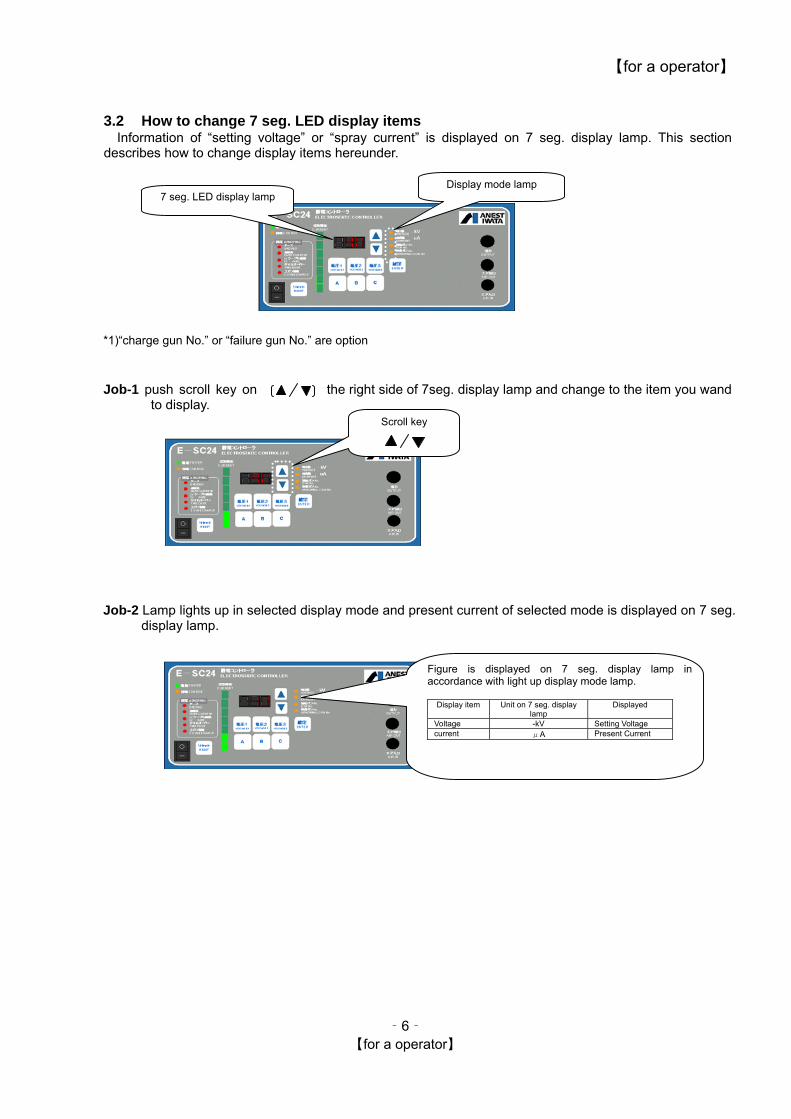
3.2 How to change 7 seg. LED display items Information of “setting voltage” or “spray current” is displayed on 7 seg. display lamp. This section
describes how to change display items hereunder.
*1)“charge gun No.” or “failure gun No.” are option
Job-1 push scroll key on the right side of 7seg. display lamp and change to the item you wand
to display.
Job-2 Lamp lights up in selected display mode and present current of selected mode is displayed on 7 seg.
display lamp.
Display mode lamp 7 seg. LED display lamp
Scroll key
Figure is displayed on 7 seg. display lamp in accordance with light up display mode lamp.
Display item Unit on 7 seg. display
lamp Displayed
Voltage -kV Setting Voltage current μA Present Current
‐6‐ 【for a operator】

【for a operator】
4 Safeguards Safeguards (failure detection functions) to monitor safety about electrostatic coating system of
electrostatic controller are explained below. 4.1 Safeguards to be monitored Contents of safeguards
Detection items Contents to be detected Safeguards
over current failure 1 When over 150μA coating current occurs and continues for over 30sec.
Immediately shutting off HV charging and sounding failure buzzer. Warning mode is kept until reset key is pushed.
over current failure 2 In case the current flows over 200μA. (Hard wear circuit protection: CP)
Immediately shutting off HV charging and sounding failure buzzer. The warning mode is kept until turning off the power switch.
LV cable failure When LV cable is damaged. Immediately shutting off charge and sounding failure buzzer. Warning mode is kept till reset key is pushed.
spray set time over When detecting continuous charge signal for over 2 minutes.
Immediately shutting off charge and sounding failure buzzer. Warning mode is kept till reset key is pushed.
high voltage
generator failure When the current supplied to high voltage generator, is in abnormal condition
Immediately shutting off charge and sounding failure buzzer. Warning mode is kept till reset key is pushed.
Indication lamp Detection name
7seg. display Power Charge Ground Over current LV cable Time
over 2 guns charge Alarm
Power on while charging signal on △ Periodical beep sound
Over current failure1 ○ Beep sound
Over current failure2 ▽ Beep sound
LV cable failure Current detecting line ○ Beep sound
Primary line of transformer △ Beep sound
Shielding wire ▲ Beep sound
Spray set time over ○ Beep sound
High voltage generator
failure E01 Beep sound
○:lighting, �:flickering (normal interval: 1sec)、▲:flickering (slow interval 2sec)、�:flickering (fast interval 0.5sec)
‐7‐ 【for a operator】

【for a operator】
4.2 Measures when warning mode appears by safeguards When electrostatic controller detects failure, buzzer sounds and warning mode appears. Follow the
following procedure, check the contents of failure and remedy. Before taking any measures, be sure to read the following warning items.
Beep!Suppose that electrostatic controller detects failure, warning buzzer sounds and charge is stopped (=warning mode)
Job-1 Suspend coating job and check failure item by lit-up position of failure display lamp.
First check failure item by failuredisplay lamp although warningbuzzer continues sounding.
‐8‐ 【for a operator】
【for a operator】
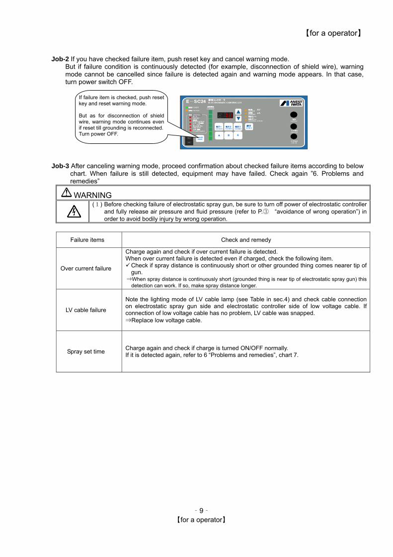
Job-2 If you have checked failure item, push reset key and cancel warning mode. But if failure condition is continuously detected (for example, disconnection of shield wire), warning mode cannot be cancelled since failure is detected again and warning mode appears. In that case, turn power switch OFF.
If failure item is checked, push resetkey and reset warning mode. But as for disconnection of shieldwire, warning mode continues evenif reset till grounding is reconnected. Turn power OFF.
Job-3 After canceling warning mode, proceed confirmation about checked failure items according to below
chart. When failure is still detected, equipment may have failed. Check again ”6. Problems and remedies”
WARNING
(1) Before checking failure of electrostatic spray gun, be sure to turn off power of electrostatic controller and fully release air pressure and fluid pressure (refer to P.③ “avoidance of wrong operation”) in order to avoid bodily injury by wrong operation.
Failure items Check and remedy
Over current failure
Charge again and check if over current failure is detected. When over current failure is detected even if charged, check the following item. Check if spray distance is continuously short or other grounded thing comes nearer tip of gun.
⇒When spray distance is continuously short (grounded thing is near tip of electrostatic spray gun) this detection can work. If so, make spray distance longer.
LV cable failure
Note the lighting mode of LV cable lamp (see Table in sec.4) and check cable connection on electrostatic spray gun side and electrostatic controller side of low voltage cable. If connection of low voltage cable has no problem, LV cable was snapped. ⇒Replace low voltage cable.
Spray set time Charge again and check if charge is turned ON/OFF normally. If it is detected again, refer to 6 “Problems and remedies”, chart 7.
‐9‐ 【for a operator】
【for a operator】
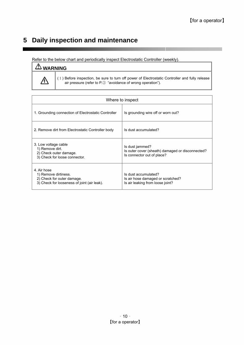
5 Daily inspection and maintenance
Refer to the below chart and periodically inspect Electrostatic Controller (weekly).
WARNING
(1) Before inspection, be sure to turn off power of Electrostatic Controller and fully release
air pressure (refer to P.③ “avoidance of wrong operation”).
Where to inspect
1. Grounding connection of Electrostatic Controller Is grounding wire off or worn out?
2. Remove dirt from Electrostatic Controller body Is dust accumulated?
3. Low voltage cable 1) Remove dirt. 2) Check outer damage. 3) Check for loose connector.
Is dust jammed? Is outer cover (sheath) damaged or disconnected? Is connector out of place?
4. Air hose 1) Remove dirtiness. 2) Check for outer damage. 3) Check for looseness of joint (air leak).
Is dust accumulated? Is air hose damaged or scratched? Is air leaking from loose joint?
‐10‐ 【for a operator】
【for a operator】
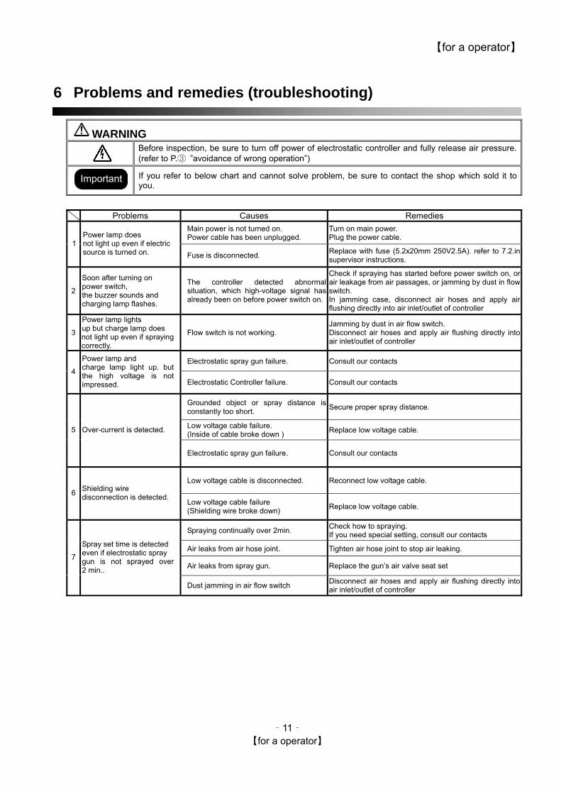
6 Problems and remedies (troubleshooting)
WARNING
Before inspection, be sure to turn off power of electrostatic controller and fully release air pressure. (refer to P.③ ”avoidance of wrong operation”)
If you refer to below chart and cannot solve problem, be sure to contact the shop which sold it to you.
Important
Problems Causes Remedies Main power is not turned on. Power cable has been unplugged.
Turn on main power. Plug the power cable.
1 Power lamp does not light up even if electric source is turned on. Fuse is disconnected. Replace with fuse (5.2x20mm 250V2.5A). refer to 7.2.in
supervisor instructions.
2
Soon after turning on power switch, the buzzer sounds and charging lamp flashes.
The controller detected abnormal situation, which high-voltage signal has already been on before power switch on.
Check if spraying has started before power switch on, or air leakage from air passages, or jamming by dust in flow switch. In jamming case, disconnect air hoses and apply air flushing directly into air inlet/outlet of controller
3
Power lamp lights up but charge lamp does not light up even if spraying correctly.
Flow switch is not working. Jamming by dust in air flow switch. Disconnect air hoses and apply air flushing directly into air inlet/outlet of controller
Electrostatic spray gun failure. Consult our contacts 4
Power lamp and charge lamp light up. but the high voltage is not impressed. Electrostatic Controller failure. Consult our contacts
Grounded object or spray distance is constantly too short. Secure proper spray distance.
Low voltage cable failure. (Inside of cable broke down ) Replace low voltage cable. 5 Over-current is detected.
Electrostatic spray gun failure. Consult our contacts
Low voltage cable is disconnected. Reconnect low voltage cable. 6 Shielding wire
disconnection is detected. Low voltage cable failure (Shielding wire broke down) Replace low voltage cable.
Spraying continually over 2min. Check how to spraying. If you need special setting, consult our contacts
Air leaks from air hose joint. Tighten air hose joint to stop air leaking.
Air leaks from spray gun. Replace the gun’s air valve seat set 7
Spray set time is detected even if electrostatic spray gun is not sprayed over 2 min..
Dust jamming in air flow switch Disconnect air hoses and apply air flushing directly into air inlet/outlet of controller
‐11‐ 【for a operator】

【for a supervisor】
- 12 - 【for a supervisor】
Electrostatic Controller E-SC24 -EX series E-SC24L-EX series
Instruction manual
< for a supervisor >

【for a supervisor】
- 13 - 【for a supervisor】
7 Specifications
7.1 Specifications Items Contents
Input voltage AC200~240V 50/60Hz single-phase Output voltage (Electrostatic Controller) MAX AC24Vpp Output current (discharge current of electrostatic spray gun) MAX 150μA (C.P 200μA )
Electric consumption ≒75W
Ambient temperature range 5℃~40℃ Ambient humidity range Less than 70%RH Safeguards Detection of over-current, LV cable failure, spray set time failure Dimensions L×W×H 245mmX150mmX130mm
Mass 3.4kg Charge ON/OFF mechanism Air flow switch(air joint IN/OUT size: G1/4 male) Max. operating air pressure (when air flow switch is used) MAX 0.68MPa
Applicable electrostatic spray gun E-SC24-EX series. ⇒ E-MW100 series E-SC24L-EX series ⇒ E-MW50 series
< Outline of electrostatic controller > This electrostatic controller is for supplying electricity to the booster circuit built into the electrostatic spray gun. It converts AC200-240V electricity to AC24Vpp and supplies the electricity to the electrostatic spray gun via a low voltage cable. (LV cable) It has built-in safeguards (detection of over current, disconnection of LV cable failure and self-diagnostic function to detect failure)
8 Check the products
This unit consists of the following accessories including electrostatic controller. Before use, be sure to check that all the products are included without any damage. If you find some products are missing or damaged, contact the shop which sold it to you.
Name of products Contents
Electrostatic Controller
(1) Grounding wire (5m)
Acce
ssor
ies
(2) Instruction manual (this one)
R1.25-4 R1.25-6
【for a supervisor】
- 14 - 【for a supervisor】
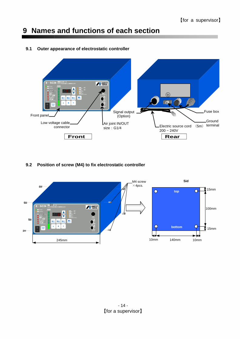
9 Names and functions of each section
9.1 Outer appearance of electrostatic controller
Rear
Electric source cord (5m)200 ~ 240V
Front
Fuse box
Low voltage cableconnector
Air joint IN/OUT size:G1/4
Front panelSignal output
(Option) Ground terminal
9.2 Position of screw (M4) to fix electrostatic controller
140mm
100mm
15mm
15mm
Sid
top
bottom
10mm
M4 screw ×4pcs. ( )
245mm 10mm
【for a supervisor】
- 15 - 【for a supervisor】
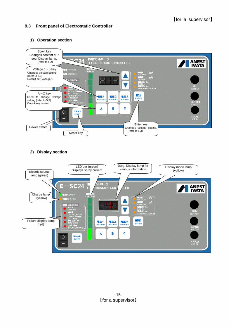
9.3 Front panel of Electrostatic Controller
1) Operation section
Reset key
Power switch
A~C key Used to change voltagesetting (refer to 5.3) Only A key is used.
Voltage 1~3 key Changes voltage setting. (refer to 5.3) Default set; voltage 1
Enter key Changes voltage setting.
(refer to 5.3)
Scroll key Changes content of 7
seg. Display lamp. (refer to 5.2)
2) Display section
Failure display lamp (red)
LED bar (green) Displays spray current
7seg. Display lamp for various information
Display mode lamp (yellow)
Charge lamp (yellow)
Electric source lamp (green)

【for a supervisor】
- 16 - 【for a supervisor】
10 Setup of Electrostatic Controller
This section explains how to set up electrostatic controller about standard connection as shown below. Before setup, be sure to observe the below warning.
WARNING
A) Before connection, be sure to turn off power switch, release pressure of primary side air
source and turn off all power switches of related equipment.
A) Securely connect grounding. Insufficient grounding can cause failure by charging of electrostatic controller, fire by spark discharge through leak, charge, or injury by electric shock.
B) Be sure to connect surrounding metallic things to ground before charging electrically. If not, it can cause fire or injury by electric shock.
A) Never use primary side electric source other than designated AC 200 ~ 240V. B) Input of different voltage than set specifications can cause damage to equipment or fire.
Ground A class
Electric source AC200 ~ 240V
Air source
Compressor
⇒ air filter ⇒ air regulator
Connect customer’s equipment
Electrostatic spray gun
E-spray series (option)
Air hose (option)
Low voltage cable(option)
Air hose (option)
Grounding wire (accessory)
Electric source cord*)
(accessory)
Standard setup
Air joint connection IN/OUT size G 1/4
Connector for low voltage cable
Caution: The earth pin of AC plug isn’t PE. It’s necessary to connect grounding wire.

【for a supervisor】
- 17 - 【for a supervisor】
10.1 Connection of electric cable
WARNING
A) Before connection, be sure to turn off power switch, release pressure of primary side air
source and turn off all power switches of related equipment.
A) Securely connect grounding. Insufficient grounding can cause failure by charging of Electrostatic Controller, fire by spark discharge through leak, charge, or injury by electric shock.
B) When charging electrically, be sure to ground all surrounding metallic things. If not, it can cause fire or injury of electric shock.
A) Never use primary side electric source other than designated AC 200 ~ 240V). B) Input of different voltage then set specifications can cause damage to equipment or fire.
Job-1 Fit attached grounding wire to grounding terminal block at back
of Electrostatic Controller. Connect the other terminal to grounding terminal of customer (we recommend A class grounding)
Job-2 Insert power cord into AC 200 ~ 240V power receptacle of customer.
Job-3 Connect low voltage cable attached to electrostatic gun to
low voltage cable connector (output) of front panel.
Ground terminal
To customer’s ground terminal (we recommend A class grounding)
Caution: The earth pin of AC plug isn’t PE(protection earth). It’s necessary to connect ground.
Low voltage cable connector
To electrostatic gun of customer
Refer to instruction manual ofElectrostatic gun about how tofit to Electrostatic gun.
【for a supervisor】
- 18 - 【for a supervisor】
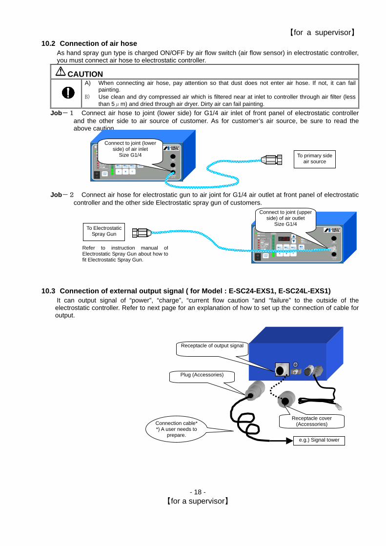
10.2 Connection of air hose As hand spray gun type is charged ON/OFF by air flow switch (air flow sensor) in electrostatic controller, you must connect air hose to electrostatic controller.
CAUTION
A) When connecting air hose, pay attention so that dust does not enter air hose. If not, it can fail painting.
B) Use clean and dry compressed air which is filtered near at inlet to controller through air filter (less than 5μm) and dried through air dryer. Dirty air can fail painting.
Job-1 Connect air hose to joint (lower side) for G1/4 air inlet of front panel of electrostatic controller and the other side to air source of customer. As for customer’s air source, be sure to read the above caution.
Job-2 Connect air hose for electrostatic gun to air joint for G1/4 air outlet at front panel of electrostatic controller and the other side Electrostatic spray gun of customers.
10.3 Connection of external output signal ( for Model : E-SC24-EXS1, E-SC24L-EXS1) It can output signal of “power”, “charge”, “current flow caution “and “failure” to the outside of the electrostatic controller. Refer to next page for an explanation of how to set up the connection of cable for output.
Connect to joint (lower side) of air inlet
Size G1/4 To primary side air source
Connect to joint (upper side) of air outlet
Size G1/4 To Electrostatic
Spray Gun
Refer to instruction manual ofElectrostatic Spray Gun about how tofit Electrostatic Spray Gun.
Plug (Accessories)
e.g.) Signal tower
Receptacle cover (Accessories) Connection cable*
*) A user needs to prepare.
Receptacle of output signal

【for a supervisor】
- 19 - 【for a supervisor】
< Construction >
Receptacle Plug
Electrostatic controller rear panel
1 2 3
4 5 6 7
8 9 10
11 12
Receptacle Plug
(Accessories)
1 2 3 4 5 6 7
9 1112
8 10
Items Signal 1 1 ON (close) 2 2 Power OFF (open) 3 3 ON (close) 4 4 Charge OFF (open) 5 5 ON (close) 6 6 Failure OFF (open) 7 7 ON (close) 8 8 Current flow caution OFF (open) 9 9 No use - 10 10 No use - 11 11 No use - 12 12 No use -
Specification (Charge input contact point) No-voltage contact point output Normal open Contact point capacity Below
250V 1A (Resistance load)
< How to connect Plug and Cable > <Job-1> Disassemble the Plug

【for a supervisor】
- 20 - 【for a supervisor】
<Job-2> Solder and connect cable. (Pay attention not to get burnt) <Job-3> Assemble the Plug <Job-4> Tighten the screw.
Connection cable
Screw Screwdriver
Soldering iron
Be careful of a burn.

【for a supervisor】
- 21 - 【for a supervisor】
11 Operation
11.1 Normal operation
WARNING
A) When charging electrically, be sure to ground all surrounding metallic things. If not it can cause fire or injury of electric shock.
CAUTION
A) During charging (when high voltage is generated), do not put electrostatic spray gun within about 50cm of Electrostatic Controller. If done, Electrostatic Controller can fail if it sparks, as Electrostatic Controller is electrical equipment.
After setup of 4 is finished, start painting according to the following procedure. Job-1 Turn on power switch.
Power lamp lights up and the gun is ready to charge (voltage key lamp, display mode lamp, 7 seg. Display lamp lights up and displays.)
Job-2 In case of hand spray
gun: if the spray gun starts to spray, air flow switch operates and gun is charged*1)
When high voltage is charged, charge lamp lights up and spray current is displayed in spray current *2) *1)Max. Voltage –60kV ( for E-SC24-EX), -50kV ( for E-SC24L-EX) is set when shipped form factory (it is set on voltage1) *2)It normally lights up about in the range of 80 ~ 130μA. But display differs according to other conditions
Job-3 In the case of spray hand
gun: if the connected spray gun ends air spray, air flow switch stops, charge stops and returns to Job-1 condition.
Job-4 If spray job is finished,
turn off power of Electrostatic Controller.
Gun sprays Air flow switch ON
Display mode lamp light up (refer to 5.2)
7 seg. Display lamp (refer to 5.2)
Voltage key lamp lights up
Default :Voltage 3 (refer to 5.3)
Electric source lamp lights up
Electric source switch ON
Charge lamp lights up Gun charge ON
Spray current display
LED bar display
Electric source OFF
Electric source lamp goes out
Display lampgoes out.
The guns spray ends, Air flow switch OFF
Charge lamp goes out, gun charge
OFF
【for a supervisor】
- 22 - 【for a supervisor】
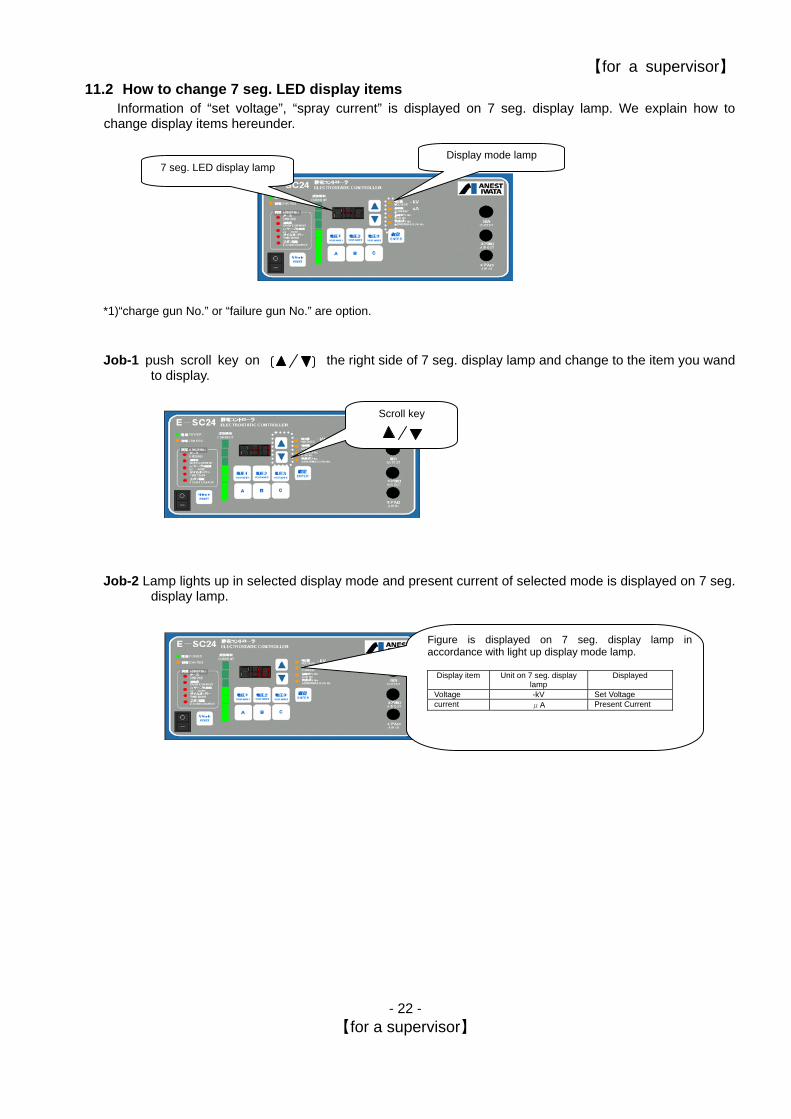
11.2 How to change 7 seg. LED display items Information of “set voltage”, “spray current” is displayed on 7 seg. display lamp. We explain how to
change display items hereunder.
*1)“charge gun No.” or “failure gun No.” are option.
Job-1 push scroll key on the right side of 7 seg. display lamp and change to the item you wand
to display.
Job-2 Lamp lights up in selected display mode and present current of selected mode is displayed on 7 seg.
display lamp.
Display mode lamp 7 seg. LED display lamp
Scroll key
Figure is displayed on 7 seg. display lamp in accordance with light up display mode lamp.
Display item Unit on 7 seg. display
lamp Displayed
Voltage -kV Set Voltage current μA Present Current
【for a supervisor】
- 23 - 【for a supervisor】
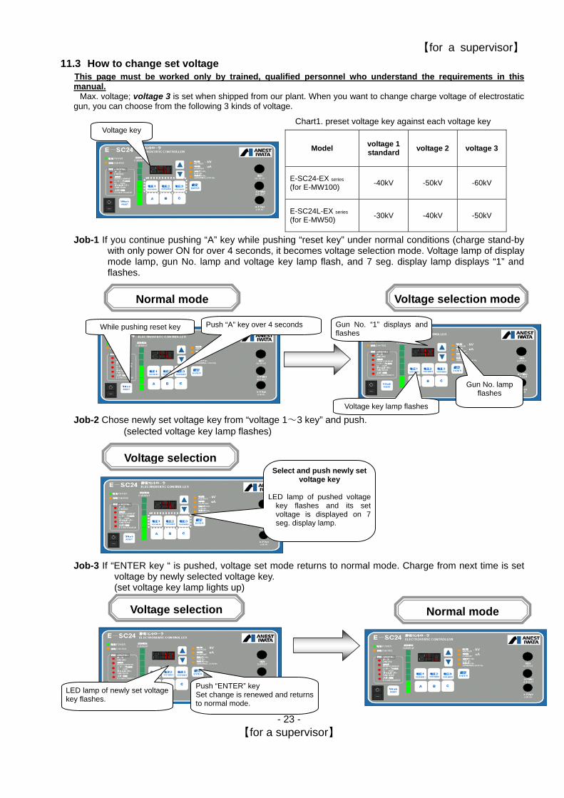
11.3 How to change set voltage This page must be worked only by trained, qualified personnel who understand the requirements in this manual.
Max. voltage; voltage 3 is set when shipped from our plant. When you want to change charge voltage of electrostatic gun, you can choose from the following 3 kinds of voltage.
Job-1 If you continue pushing “A” key while pushing “reset key” under normal conditions (charge stand-by
with only power ON for over 4 seconds, it becomes voltage selection mode. Voltage lamp of display mode lamp, gun No. lamp and voltage key lamp flash, and 7 seg. display lamp displays “1” and flashes.
Job-2 Chose newly set voltage key from “voltage 1~3 key” and push. (selected voltage key lamp flashes)
Job-3 If “ENTER key “ is pushed, voltage set mode returns to normal mode. Charge from next time is set
voltage by newly selected voltage key. (set voltage key lamp lights up)
Chart1. preset voltage key against each voltage key Voltage key
Model voltage 1 standard voltage 2 voltage 3
E-SC24-EX series
(for E-MW100) -40kV -50kV -60kV
E-SC24L-EX series (for E-MW50) -30kV -40kV -50kV
While pushing reset key Push “A” key over 4 seconds
Voltage selection modeNormal mode
Gun No. “1” displays andflashes
Voltage key lamp flashes
Select and push newly set voltage key
LED lamp of pushed voltage
key flashes and its setvoltage is displayed on 7seg. display lamp.
Gun No. lamp flashes
Voltage selection
Normal modeVoltage selection
LED lamp of newly set voltagekey flashes.
Push “ENTER” key Set change is renewed and returnsto normal mode.

【for a supervisor】
- 24 - 【for a supervisor】
12 Safeguards
Safeguards (failure detection functions) to monitor safety about electrostatic coating system of electrostatic controller are explained below.
1.1 Safeguards to be monitored Contents of safeguards
Detection items Contents to be detected Safeguards
over current failure 1 When over 150μA coating current occurs and continues for over 30sec.
Immediately shutting off HV charging and sounding failure buzzer. Warning mode is kept until reset key is pushed.
over current failure 2 In case the current flows over 200μA. (Hard wear circuit protection: CP)
Immediately shutting off HV charging and sounding failure buzzer. The warning mode is kept until turning off the power switch.
LV cable failure When LV cable is damaged. Immediately shutting off charge and sounding failure buzzer. Warning mode is kept till reset key is pushed.
spray set time over When detecting continuous charge signal for over 2 minutes.
Immediately shutting off charge and sounding failure buzzer. Warning mode is kept till reset key is pushed.
high voltage
generator failure When the current supplied to high voltage generator, is in abnormal condition
Immediately shutting off charge and sounding failure buzzer. Warning mode is kept till reset key is pushed.
Indication lamp Detection name
7seg. display Power Charge Ground Over current LV cable Time
over 2 guns charge Alarm
Power on while charging signal on △ Periodical beep sound
Over current failure1 ○ Beep sound
Over current failure2 ▽ Beep sound
LV cable failure Current detecting line ○ Beep sound
Primary line of transformer △ Beep sound
Shielding wire ▲ Beep sound
Spray set time over ○ Beep sound
High voltage generator
failure E01 Beep sound
○:lighting, △:flickering (normal interval: 1sec)、▲:flickering (slow interval 2sec)、▽:flickering
(fast interval 0.5sec)

【for a supervisor】
- 25 - 【for a supervisor】
12.1 Measures when warning mode appears by safeguards When electrostatic controller detects failure, buzzer sounds and warning mode appears. Follow the
following procedure, check the contents of failure and remedy. Before taking any measures, be sure to read the following warning items.
Job-1 Suspend coating job and check failure item by lit-up position of failure display lamp.
Job-2 If you have checked failure item, push reset key and cancel warning mode.
But if failure condition is continuously detected (for example, disconnection of shield wire), warning mode cannot be cancelled since failure is detected again and warning mode appears. In that case, turn power switch OFF.
Beep!Suppose that electrostatic controller detects failure, warning buzzer sounds and charge is stopped (=warning mode)
First check failure item by failuredisplay lamp although warningbuzzer continues sounding.
If failure item is checked, push resetkey and reset warning mode. But as for disconnection of shieldwire, warning mode continues evenif reset till grounding is reconnected. Turn power OFF.
【for a supervisor】
- 26 - 【for a supervisor】
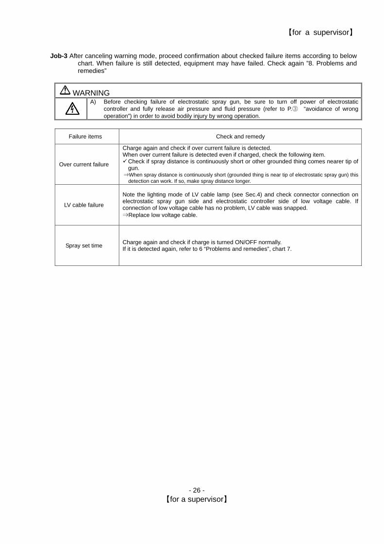
Job-3 After canceling warning mode, proceed confirmation about checked failure items according to below
chart. When failure is still detected, equipment may have failed. Check again ”8. Problems and remedies”
WARNING A) Before checking failure of electrostatic spray gun, be sure to turn off power of electrostatic
controller and fully release air pressure and fluid pressure (refer to P.③ “avoidance of wrong operation”) in order to avoid bodily injury by wrong operation.
Failure items Check and remedy
Charge again and check if over current failure is detected.
Over current failure
When over current failure is detected even if charged, check the following item. Check if spray distance is continuously short or other grounded thing comes nearer tip of gun.
⇒When spray distance is continuously short (grounded thing is near tip of electrostatic spray gun) this detection can work. If so, make spray distance longer.
LV cable failure
Note the lighting mode of LV cable lamp (see Sec.4) and check connector connection on electrostatic spray gun side and electrostatic controller side of low voltage cable. If connection of low voltage cable has no problem, LV cable was snapped. ⇒Replace low voltage cable.
Spray set time Charge again and check if charge is turned ON/OFF normally. If it is detected again, refer to 6 “Problems and remedies”, chart 7.
【for a supervisor】
- 27 - 【for a supervisor】
13 Daily inspection and maintenance
13.1 Daily inspection and maintenance Refer to the below chart and periodically inspect Electrostatic Controller (weekly).
WARNING A) Before inspection, be sure to turn off power of Electrostatic Controller and fully release
air pressure (refer to P.③ “avoidance of wrong operation”).
Where to inspect
1. Grounding connection of Electrostatic Controller Is grounding wire off or worn out? 2. Remove dirt from Electrostatic Controller body Is dust accumulated? 3. Low voltage cable
1) Remove dirt. 2) Check outer damage. 3) Check for loose connector.
Is dust accumulated? Is outer cover (sheath) damaged or disconnected? Is connector out of place?
4. Air hose 1) Remove dirtiness. 2) Check for outer damage. 3) Check for looseness of joint (air leak).
Is dust accumulated? Is air hose damaged or scratched? Is air leaking from loose joint?
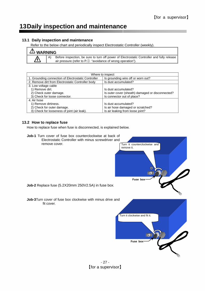
13.2 How to replace fuse How to replace fuse when fuse is disconnected, is explained below. Job-1 Turn cover of fuse box counterclockwise at back of
Electrostatic Controller with minus screwdriver and remove cover.
Job-2 Replace fuse (5.2X20mm 250V2.5A) in fuse box. Job-3Turn cover of fuse box clockwise with minus drive and
fit cover.
Turn it counterclockwise andremove it.
Fuse box
Fuse box
Turn it clockwise and fit it.

【for a supervisor】
- 28 - 【for a supervisor】
14 Parts List
No. E-SC24(L)-EX E-SC24(L)-EX-S1 1
E-SC24(L)-EX 1 1
2 Fuse 1 1 3 Connector plug - 1
E-SC24(L)-EX
2
1 1
2
3 E-SC24(L)-EXS1

【for a supervisor】
- 29 - 【for a supervisor】
15 Problems and remedies (troubleshooting)
WARNING A) Before inspection, be sure to turn off power of electrostatic controller and fully release air
pressure. (refer to P.③ ”avoidance of wrong operation”)
A) If you refer to below chart and cannot solve problem, be sure to contact the shop which sold it to you. Important
Problems Causes Remedies Main power is not turned on. Power cable has been unplugged.
Turn on main power. Plug the power cable.
1 Power lamp does not light up even if electric source is turned on. Fuse is disconnected. Replace with fuse (5.2x20mm 250V2.5A). refer to 7.2.in
supervisor instructions.
2
Soon after turning on power switch, the buzzer sounds and charging lamp flashes.
The controller detected abnormal situation, which high-voltage signal has already been on before power switch on.
Check if spraying has started before power switch on, or air leakage from air passages, or jamming by dust in flow switch. In jamming case, disconnect air hoses and apply air flushing directly into air inlet/outlet of controller
3
Power lamp lights up but charge lamp does not light up even if spraying correctly.
Flow switch is not working. Jamming by dust in air flow switch. Disconnect air hoses and apply air flushing directly into air inlet/outlet of controller
Electrostatic spray gun failure. Consult our contacts 4
Power lamp and charge lamp light up. but the high voltage is not impressed. Electrostatic Controller failure. Consult our contacts
Grounded object or spray distance is constantly too short. Secure proper spray distance.
Low voltage cable failure. (Inside of cable broke down ) Replace low voltage cable. 5 Over-current is detected.
Electrostatic spray gun failure. Consult our contacts
Low voltage cable is disconnected. Reconnect low voltage cable. 6 Shielding wire
disconnection is detected. Low voltage cable failure (Shielding wire broke down) Replace low voltage cable.
Spraying continually over 2min. Check how to spraying. If you need special setting, consult our contacts
Air leaks from air hose joint. Tighten air hose joint to stop air leaking.
Air leaks from spray gun. Replace the gun’s air valve seat set 7
Spray set time is detected even if electrostatic spray gun is not sprayed over 2 min..
Dust jamming in air flow switch Disconnect air hoses and apply air flushing directly into air inlet/outlet of controller

Warranty
All ANEST IWATA s.r.l. products have a one-year guarantee from the invoice date, unless otherwise stated in writing. The warranty covers all manufacturing faults and material defects. Any spare part replacement or repair operations are covered only if they are carried out by our technicians at servicing shops.
The faulty parts must be sent CARRIAGE PAID. Once the components have been repaired, they will be sent CARRIAGE FORWARD to the customer.
The warranty covers no intervention of our technicians during installation or dismantling operations. If for practical purposes one of our technicians is sent on site, a charge will be made for the time plus extra for traveling and expenses.
Our warranty dose not cover direct or indirect damage to people or property caused by our equipment. It covers no repair operations carried out by the customer or by a third party, either.
THE WARRANTY DOES NOT COVER
Damage or breakdown caused by improper use or assembly
Damage or breakdown caused by the use of spare parts that are different form the original or recommended ones.
Damage or breakdown caused by a bad preservation.
Components subject to wear (described in the spare part list.)
WARRANTY FORFEITURE:
In case of delayed payment or other contractual defaults.
Whenever changes or repairs are carried out on our equipment without prior authorization.
Whenever the serial number is damaged or removed.
When the damage is caused by improper use or functioning, or if the equipment falls, is bumped or by other causes not due to the normal working conditions.
Whenever the unit is disassembled, tampered with or repaired without the authorization of ANEST IWATA s.r.l.
All repair interventions carried out under warranty do not interrupt its duration.
All disputed will be settled in the court of justice of Turin.

Service contact

3176, Shinyoshida-cho, kouhoku-ku,
Yokohama-shi, Kanagawa-ken, 223-8501 Japan
Instruction manual No.T078-00
Code No. 03538070