instruction manual em39003 05/10
TRANSCRIPT

Instruction ManualEM39003
05/10
39003 SeriesHigh Performance Butterfly Valves
Putting You In Control

CopyrightMasoneilan® is a registered trademark of Dresser, Inc. All information contained herein is believed to be accurate at the time of publication and is subject to change without notice.
Copyright 2010 by Dresser, Inc. All rights reserved.
The following Instructions should be thoroughly reviewed and understood prior to installing, operating or performing maintenance on this equipment. Throughout the text, safety and/or caution notes will appear and must be strictly adhered to, otherwise, serious injury or equipment malfunction could result.
Table of Contents Page
1. InTRODUCTIOn 1.1 VALVE DESCRIPTIOn ..........................................................................................2 1.2 VALVE DESIgn FEATURES .................................................................................2 1.3 FLAngE COMPATIbILITy ....................................................................................2 1.4 gASkET COMPATIbILITy ....................................................................................2 1.5 PIPE SCHEDULE COMPATIbILITy ......................................................................2 1.6 nUMbERIng SySTEM ........................................................................................3 1.7 OPERATIng PRESSURES ...................................................................................5 1.8 SEAT ALTERnATIVES ..........................................................................................5 1.9 OFFSET DISC DESIgn ........................................................................................5 1.10 SEAT RETAInER ALTERnATIVES ........................................................................6
2. InSTALLATIOn RECOMMEnDATIOnS 2.1 VALVE RATIngS ..................................................................................................6 2.2 SEAT UPSTREAM vs. SEAT DOWnSTREAM .......................................................6 2.3 DISC CLEARAnCES ............................................................................................7 2.4 OPEnIng ROTATIOn ..........................................................................................7 2.5 InSTALLATIOn POSITIOn ...................................................................................7 2.6 VALVE AnD FLAngE PREPARATIOn ..................................................................7 2.7 InSTALLATIOn TOOLS ........................................................................................7 2.8 REqUIRED bOLTIng ...........................................................................................7 2.9 UnPACkIng AnD STORAgE InSTRUCTIOnS ....................................................7 2.10 PRE-InSTALLATIOn PROCEDURE ......................................................................7 2.11 VALVE InSTALLATIOn PROCEDURE ..................................................................7 2.12 ACTUATOR InSTALLATIOn .................................................................................8 2.13 bOLTIng DIMEnSIOnS .......................................................................................9
3. MAInTEnAnCE InSTRUCTIOnS 3.1 SAFETy PRECAUTIOnS ....................................................................................11 3.2 gEnERAL MAInTEnAnCE ................................................................................11 3.3 PACkIng REPLACEMEnT ................................................................................11 3.4 EnD CAP SEAL REPLACEMEnT .......................................................................11 3.5 STAnDARD SOFT SEAT REPLACEMEnT .........................................................11 3.6 FIRE-SAFE AnD METAL SEAT REPLACEMEnT ................................................12 3.7 DISC, SHAFT AnD bEARIng REPLACEMEnT ..................................................13 3.8 VALVE PARTS LIST ...........................................................................................14 3.9 REMOTE ACTUATOR (MALE DRIVE) MOUnTIng PROCEDURE .......................15 3.10 REMOTE ACTUATOR (FEMALE DRIVE) MOUnTIng PROCEDURE ...................15 3.11 33 ACTUATOR DISASSEMbLy .........................................................................16 3.12 ACTUATOR DIAPHRAgM REPLACEMEnT .......................................................17 3.13 33 ACTUATOR REASSEMbLy ..........................................................................18 3.14 ACTUATOR PARTS LIST ...................................................................................20

Safety InformationImportant - Please Read Before InstallationMasoneilan 39003 Series High Performance butterfly Valves instructions contain DANGER, WARNING, and CAUTION labels, where necessary, to alert you to safety related or other important information. Read the instructions carefully before installing and maintaining your control valve. DANGER and WARNING hazards are related to personal injury. CAUTION hazards involve equipment or property damage. Operation of damaged equipment can, under certain operational conditions, result in degraded process system performance that can lead to injury or death. Total compliance with all DANGER, WARNING, and CAUTION notices is required for safe operation.
This is the safety alert symbol. It alerts you to potential personal injury hazards. Obey all safety messages that follow this symbol to avoid possible injury or death.
Indicates a potentially hazardous situation which, if not avoided, could result in death or serious injury.
Indicates a potentially hazardous situation which, if not avoided, could result in serious injury.
Indicates a potentially hazardous situation which, if not avoided, could result in minor or moderate injury.
When used without the safety alert symbol indicates a potentially hazardous situation which, if not avoided, could result in property damage.
Note: Indicates important facts and conditions.
About this Manual• The information in this manual is subject to change without
prior notice.
• The information contained in this manual, in whole or part, shall not be transcribed or copied without Masoneilan’s written permission.
• Please report any errors or questions about the information in this manual to your local supplier.
• These instructions are written specifically for the 39003 Series High Performance butterfly Valves, and do not apply for other valves outside of this product line.
WarrantyItems sold by Dresser® are warranted to be free from defects in materials and workmanship for a period of one year from the date of shipment provided said items are used according to Dresser recommended usages. Dresser, Inc. reserves the right to discontinue manufacture of any product or change product materials, design or specifications without notice.
This instruction manual applies to the Masoneilan 39003 Series High Performance butterfly Valves.
The Control Valve and Actuator MUST bE:
• Installed, put into service and maintained by qualified and competent professionals who have undergone suitable training.
• Under certain operating conditions, the use of damaged equipment could cause a degradation of the performance of the system which may lead to personal injury or death.
• Changes to specifications, structure, and components used may not lead to the revision of this manual unless such changes affect the function and performance of the product.
• All air supply to the actuator must be turned off.
• All surrounding pipe lines must be thoroughly flushed to ensure all entrained debris has been removed from the system.
Instructions EM39003 - 05/1039003 Series High Performance butterfly Valves 1

Instructions EM39003 - 05/1039003 Series High Performance butterfly Valves 2
1. Introduction1.1 Valve Description
The Masoneilan 39003 Series High Performance butterfly Valve (HPbV) is designed for AnSI Class 150, 300 and 600 piping systems and is available in both Wafer and Lug style body designs. The standard size range available is as follows:
AnSI Class 150 ........................ 2" through 48"
AnSI Class 300 ........................ 2" through 30"
AnSI Class 600 ........................ 2" through 16"
1.2 Valve Design Features
• Masoneilan’s HPbVs feature a double offset (or double eccentric) shaft design to minimize seat abrasion and lower torque. This double offset design allows the disc to lift off and “cam” away from the seat as it rotates open.
• The 39003 Series valve always rotates clockwise to close (when viewed from above) and counterclockwise to open.
• The valve body has an overtravel stop which prevents the disc from over rotating into the wrong quadrant. This stop is not to be used as a disc position stop; if the disc contacts the overtravel stop, this means it has rotated beyond the seat.
• The 39003 Series valve is bi-directional, but the preferred installation position is with the seat in the upstream position (SUS). note the arrow on the metal tag attached to the valve body for preferred direction of flow.
1.3 Flange Compatibility
The 39003 Series valve is designed to fit between flanges as follows:
AnSI Class 150 ........................ 2" through 24"
MSS SP-44 Class 150 ............. 30" through 48"
AnSI Class 300 ........................ 2" through 24"
MSS SP-44 Class 300 ............. 30"
AnSI Class 600 ........................ 2" through 16"
1.4 Gasket Compatibility
The 39003 Series valve is designed to accommodate the use of standard fiber gaskets (such as non-asbestos, flexible graphite, asbestos or equivalent gasket materials) of 1/16" or less, meeting the dimensional requirements of AnSI/ASME b16.21. Thick elastomeric gaskets are not recommended. Metallic wound (Flexitallic) gaskets may be used with the wedge ring retainer configuration.
1.5 Pipe Schedule Compatibility
The 39003 Series valve is designed to allow the disc edge to rotate into the open position without interference with pipe of a schedule equal to or lighter to those shown below:
Size ANSI 150 ANSI 300 ANSI 600
2" – 12" SCH 80 SCH 80 SCH 120
14" – 24" SCH 40 SCH 80 SCH 120
30" SCH 30 SCH 80
36" – 42" STD WT
48" XS

Instructions EM39003 - 05/1039003 Series High Performance butterfly Valves 3
2nd3
Body Series
39
2nd9
5th3
4th3rd
33 Spring Diaphragm (Air to extend action only with or without auxilliary handwheel)
1st3
1st3
Actuator Type Design Series
3
*Standard Actuator Mounting Arrangement
Note 1: Looking at valve from actuator and bracket end, valve would not be visible.
Note 2: Positions 1, 2, 5 and 6 shown dotted and obtained by rotating the valve 180° about its shaft axis.
Caution: The valve must not be installed with the actuator mounted vertically below center.
Figure 1
ATCFTO
ATO FTO
ATOFTO
Actuator Mounting
0. Undefined
1. Horizontal above center. Valve opens on stem extension (air-to-open action)
2. Horizontal above center. Valve closes on stem extension (air-to-close action)
*3. Vertical above center. Valve opens on stem extension (air-to-open action)
*4. Vertical above center. Valve closes on stem extension (air-to-close action)
5. Horizontal below center. Valve opens on stem extension (air-to-open action)
6. Horizontal below center. Valve closes on stem extension (air-to-close action)
7. Vertical above center. Valve opens on stem extension (air-to-open action)
8. Vertical above center. Valve closes on stem extension (air-to-close action)
1.6 Numbering System
Seal Type
1. PTFE or RTFE Seal Ring
2. Inconel Seal Ring
3. Fire-Safe Seal Ring
ATCFTO

Instructions EM39003 - 05/1039003 Series High Performance butterfly Valves 4
2nd4
2nd9
5th3
4th3rd1st3
1st3
Figure 2
Seal Type
1. PTFE or RTFE Seal Ring
2. Inconel Seal Ring
3. Fire-Safe Seal Ring
Body Series
3934 Double acting or spring return piston actuator
Actuator TypeDesign Series
3
Actuator Mounting
0. Undefined
*1. Parallel to pipe. Air to open action.
*2. Parallel to pipe. Air to close action.
3. Perpendicular to pipe. Air to open action.
4. Perpendicular to pipe. Air to close action.
5. Parallel to pipe. Air to open action.
6. Parallel to pipe. Air to close action.
7. Perpendicular to pipe. Air to open action.
8. Perpendicular to pipe. Air to close action.
* Standard Actuator Mounting Arrangement

Instructions EM39003 - 05/1039003 Series High Performance butterfly Valves 5
1.7 Operating Pressures
All Masoneilan HPbVs may be applied to full AnSI ratings. However, different materials of construction may affect the rated pressure. The shut-off pressure rating is determined by the valve shaft and disc materials as well as the seat design, and is reflected on the metal identification tag attached to the valve.
1.8 Seat Alternatives
Masoneilan HPbVs have three alternatives, all of which are bi-directional.
Soft Seats provide tight shut-off to zero leakage specifications. Standard Soft Seat material includes virgin TFE or reinforced TFE (RTFE).
Fire-Safe Seats are designed for critical piping applications in installations such as Refinery and Petrochemical Plants. These seats are a combination of both metal and soft seats with the metal seat being designed to function during and after a fire. Valves of this type are referred to as “Fire-Safe” and are tested to meet API 607 “Fire-Safe” specifications and operation criteria.
Metal Seats are well suited for higher temperature applications and provide shut-off to AnSI b16.104 Class IV.
1.9 Offset Disc Design
All Masoneilan HPbVs have both off-set discs and eccentric shafts. The off-set is applicable to the disc edge seating surface relative to the shaft center line. by off-setting the seating surface from the rotational center line, a contact with the seat is possible throughout the 360° circumference. The shaft is eccentric in the body by 0.060 inches and this enhances seat life by imparting a camming action to the disc as it rotates both in and out of the seat. Seat wear points are eliminated at the top and bottom of the disc and operating torque is reduced.
Soft Seat Profile
Fire-Safe Seat Profile
Metal Seat Profile
Figure 3
Figure 4
Figure 5
Figure 6

Instructions EM39003 - 05/1039003 Series High Performance butterfly Valves 6
1.10 Seat Retainer Alternatives
Masoneilan HPbVs are designed to be easily maintained and, in particular, to allow rapid and simple replacement of the seat. The seat is held in the valve body by a seat retainer which,
Cap Screw Retainer
(The retainer is held to the valve body by cap screws recessed in the retainer face.)
Wedge Ring Retainer
(A wedge ring is forced outward into a groove machined in the body by the insertion of set screws in the face of the retainer.)
Figure 7
Figure 8
when assembled, becomes part of the raised face flange mating surface. Two types of seat retainer fastening designs are used in Masoneilan HPbVs.
Installation Recommendations2.1 Valve Ratings
Masoneilan HPbVs are intended for use at the pressure and temperatures indicated on the metal nameplate attached to each individual valve. Check the valve operating temperature and pressure ratings on the valve nameplate before proceeding with installation.
2.2 Seat Upstream vs. Seat Downstream
Although all Masoneilan seat designs are completely bi-directional, every effort should be made to install the valve with pressure and flow from the seat side of the valve (seat upstream). Positive shutoff will be achieved with the valve in either orientation. However, installation with the seat in the upstream position will result in longer service life and lower torque values.

7Instructions EM39003 - 05/1039003 Series High Performance butterfly Valves 7
2.3 Disc Clearances
Prior to installing the valve, it is important to make sure the ID of the pipe and pipe flanges is large enough to allow the disc edge to swing into the opening without interference. Damage to the disc edge can severely affect the performance of the valve. Pipe schedule compatibility for Masoneilan valves is shown in Section 1.5 of this manual.
2.4 Opening Rotation
The Masoneilan valve is designed to open with counterclockwise rotation of the shaft, and to close with clockwise rotation of the shaft when viewed from above with the shaft in the vertical position. An overtravel stop is provided in the body to prevent overtravel of the disc in the wrong direction. This stop is not to be used as a disc position stop. Contact with this stop means the disc has travelled past the seat.
2.5 Installation Position
To prevent damage during installation, the valve disc must be fully closed before installing the valve in the line. It is preferable to install HPbVs with the shaft horizontal. This is important for valves applied to fluids which contain particulates. For HPbVs 16" and larger, installation should always be made with the shaft in the horizontal position.
2.6 Valve and Flange Preparation
If the valve and mating pipe are properly prepared for installation, future problems can be avoided. All valve and pipe flange faces should be free of dirt, grit, indentations, or surface irregularities which may disrupt flange sealing and cause external leakage. The valve seat and disc sealing surface should also be inspected to eliminate any dirt or foreign material that will adversely affect the operation of the valve.
2.7 Installation Tools
The only tool required in the installation of a Masoneilan HPbV is a wrench suitable for tightening the flange bolts and/or nuts required to secure the valve in-line. A hoist may be required for handling valves 10" and larger. Smaller sized valves can usually be installed by hand. Temporary pipe supports may be used to keep mating flange faces parallel in order to aid in valve installation.
2.8 Required Bolting
The tables outlined on the following pages are furnished to provide information regarding the size, type, and quantity of bolting recommended for the installation of Masoneilan HPbVs. These tables are intended for use as a planning and procurement guide. All recommendations are based on pipe flanges in accordance with AnSI b16.5 for 2" through 24" valves and AnSI b16.47 Class A for valves 30" and larger. Flange bolting is not included with the valve shipment.
2.9 Unpacking and Storage Instructions
1. Check the packing list against the valve received to verify that the size, material, and trim are correct.
2. Check to make sure that the valve and operator were not damaged during shipment.
3. When lifting the valve, take care to avoid damage to the flange faces, disc sealing edge, or operator. On larger valves, lifting holes are provided on the periphery of the valve body to aid in valve handling.
4. If the valve is to be stored before being installed, it should be protected from harsh environmental conditions.
5. Store the valve with the disc in the closed position to protect the sealing edge and the seat.
6. keep the valve in a clean location, away from dirt, debris and corrosive materials.
7. keep the valve in a dry area with the flange protectors attached and on a suitable skid or pallet.
8. keep the valve in a cool location if possible, out of direct sunlight.
2.10 Pre-Installation Procedure
1. Remove the protective flange covers from the valve.
2. Inspect the valve to be certain the waterway is free from dirt and foreign matter. be certain the adjoining pipeline is free from any foreign material such as rust and pipe scale or welding slag that could damage the seat and disc sealing surfaces.
3. Actuators should be mounted on the valve prior to installation to facilitate proper alignment of the disc in the valve seat.
4. The valve should be in the closed position. Make sure the open and closed positions of the actuator correspond to the counterclockwise to open direction of rotation of the valve.
5. Cycle the valve to the fully open position, then back to the fully closed position, checking the actuator travel stop settings for proper disc alignment.
6. Check the valve identification tag for valve class, materials, and operating pressure to be sure they are correct for the application.
Personal injury or property damage may result if the valve is installed where service conditions could exceed the valve ratings.
7. Check the flange bolts or studs for proper size, threading and length.
2.11 Valve Installation Procedure
The Masoneilan 39003 Series High Performance butterfly Valve can be installed in the pipeline with the shaft in the vertical, horizontal, or other intermediate position. based on applications experience, however, in media with concentrations of solid or abrasive particles or media subject to solidification buildup, valve performance and service life will be enhanced by mounting the valve with the shaft in the horizontal position.
All Masoneilan valves are bi-directional and can be mounted in the pipeline in either flow direction; however, the preferred flow direction for all seat styles and materials is with the seat retainer ring located upstream to provide maximum seat protection.

Instructions EM39003 - 05/1039003 Series High Performance butterfly Valves 8
1. For Wafer Style Valves:
A. Loosely install the lower flange bolts to form a cradle between the flanges. (See Figure 9.)
B. noting the flow direction arrow on the tag, place the valve and flange gaskets between the flanges, making sure the arrow on the tag points in the direction of the flow.
C. Install the remaining flange bolts, shifting the valves as necessary to permit the bolts to pass by or through the valve body.
Figure 9 For Lug Style Valves:
A. noting the flow direction arrow on the tag, place the valve between the flanges, making sure the arrow on the tag points in the direction of the flow.
B. Install the lower flange bolts loosely, leaving space for the flange gaskets.
C. After inserting the flange gaskets, install the remaining bolts.
2. Using the sequence shown in Figure 10 tighten the flange bolts evenly to assure uniform gasket compression.
The valve should be centered between the flanges and gaskets to prevent damage to the disc edge and shaft as a result of the disc striking the flange, gasket, or pipe.
Figure 10
3. If an actuator is to be used, air hoses or electricity should be connected to the unit as specified.
4. The valve is now ready for operation.
Remember: Install the valve with the disc in the FULL CLOSED POSITION.
2.12 Actuator Installation
1. Actuator Air Piping
The Model 33 actuator used with the High Performance butterfly Valve is designed to accept 1/4" nPT air supply piping. Use 1/4" OD tubing or equivalent for all air lines. If the air line exceeds 25 ft. in length, or the valve is equipped with volume boosters, 3/8" tubing is preferred. All connections must be free of leaks.
Do not exceed loading pressure indicated on a warning tag located on the upper diaphragm case.
2. Changing Actuator Position
For each valve action, air to open or air to close, the actuator and bracket may be mounted in any one of four recommended positions (see Figure 1). Actuator position is usually determined by adjacent piping, obstacles of various types or piping arrangements. Valves may be rotated 180° around the axis of the shaft, if necessary. In such a case, no disassembly is required, other than repositioning gauges so they are not upside down. (However, note caution in Figure 1). note also that the preferred flow direction is reversed. If it becomes necessary to rotate the actuator position 90°, partial disassembly is required. Depending on whether the valve is or is not equipped with a handwheel, select the appropriate section in this instruction and proceed.
3. Changing Actuator Action
For the positions shown in Figure 1, the valve action is air to open or air to close. In both cases the actuator stem extends with admission of air to the actuator. Changing valve action requires partial disassembly in repositioning the actuator to the other hole in the bracket and reorientation of linkage. Refer to Figures 19 and 20. If the valve is equipped with a handwheel, it must be repositioned to the opposite side of the bracket.
Note: The handwheel is always installed so it operates against the actuator spring force. The handwheel is always located on the same side of the bracket as the actuator (see Figures 19 and 20). Depending on whether the valve is or is not equipped with a handwheel, select the appropriate section on disassembly and proceed.

2.13 Bolting Dimensions
9Instructions EM39003 - 05/1039003 Series High Performance butterfly Valves
Class 150 2" – 24"Class 150 30" – 48"
Lug Valves Wafer Valves
Studs & Nuts Machine Bolts Studs & Nuts
ValveSize
ValveSeries
ThreadSize
QtyC
LengthC
QtyD
LengthD
QtyF
LengthF
QtyG
LengthG
QtyE
LengthE
2" g 5/8-11 4 2.50 4 2.50 4 1.63 4 1.63 4 5.50
3" g 5/8-11 4 3.25 4 2.50 4 2.25 4 1.63 4 6.00
4" g 5/8-11 8 3.00 8 2.75 8 2.12 8 1.88 8 6.00
6" g ¾-10 8 3.50 8 3.00 8 2.50 8 1.88 8 6.50
8" g ¾-10 8 3.75 8 3.25 8 2.70 8 2.13 8 7.00
10" g 7/8-9 12 4.25 12 3.50 12 3.00 12 2.25 12 7.50
12" g 7/8-9 12 4.75 12 3.50 12 3.45 12 2.35 12 8.50
14" g 1-8 12 5.00 12 4.00 12 3.75 12 2.70 12 9.50
16" g 1-8 16 5.50 16 4.25 16 4.12 16 2.75 16 10.00
18" g 11/8-8 16 5.75 16 4.75 16 4.38 16 3.25 16 11.00
20"g 11/8-8 16 6.75 16 4.75 16 5.12 16 3.25 16 11.50
g 11/8-8 4** 5.50 4** 4.75 4** 4.12 4** 3.25 4** 5.50
24" g 11/8-8 20 7.25 20 5.75 20 5.63 20 4.25 20 13.00
30"H 1¼-8 24 7.75 24 7.75 24 6.25 24 6.25 24 16.00
H 1¼-8 4** 6.50 4** 6.25 4** 5.00 4** 4.63 4** 6.50
36"H 1½-8 28 9.50 28 9.50 28 7.75 28 7.75 28 19.50
H 1½-8 4** 7.50 4** 7.25 4** 5.75 4** 5.50 4** 7.50
42"H 1½-8 32 10.00 32 10.00 32 8.50 32 8.25 32 20.50
H 1½-8 4** 8.25 4** 7.50 4** 6.50 4** 5.75 4** 8.25
48"H 1½-8 40 11.75 40 11.00 40 9.88 40 9.25 40 23.00
H 1½-8 4** 9.00 4** 8.25 4** 7.12 4** 6.50 4** 9.00
Length of machine bolts based on:1. gasket thickness of 0.06 inches.2. Minimum flange thickness of weld neck flanges per AnSI b16.5 and b16.47 Series A.**Variation to specified bolting length may result in improper installation.
Every effort is made to provide accurate information, but no liability for claims arising from erroneous data will be accepted by Dresser.

Instructions EM39003 - 05/1039003 Series High Performance butterfly Valves 1010
ANSI Class 300 2" – 24"MSS SP-44 Class 300 30"
Lug ValvesWafer Valves
Bolt Engagement in Valve* Studs & Nuts Machine Bolts Studs & Nuts
ValveSize
ValveSeries
ThreadSize
Qty A
LengthA
QtyB
LengthB
QtyC
LengthC
QtyD
LengthD
QtyF
LengthF
QtyG
LengthG
QtyE
LengthE
2" g 5/8-11 8 .940 8 .570 8 2.25 8 2.62 8 1.50 8 2.00 8 5.25
3" g ¾-10 8 1.034 8 .826 8 3.00 8 3.00 8 2.12 81 2.00 8 6.00
4" g ¾-10 8 1.196 8 .870 8 3.50 8 3.25 8 2.50 8 2.00 8 6.50
6" g ¾-10 12 1.301 12 .929 12 3.75 12 3.50 12 2.75 12 2.25 12 7.00
8" g 7/8-9 12 1.702 12 1.128 12 4.50 12 4.00 12 3.25 12 2.75 12 8.25
10"g 1-8 16 1.867 16 1.300 16 5.00 16 4.50 16 3.25 16 3.12 14 9.25
g 1-8 - - - - - - - - - - - - 4** 5.00
12"g 11/8-8 16 2.057 16 1.475 16 5.50 16 5.00 16 4.00 16 3.38 12 10.00
g 11/8-8 - - - - - - - - - - - - 8** 5.25
14"H 11/8-8 16 2.442 16 2.118 16 6.00 16 5.75 16 4.62 16 4.25 16 11.50
H 11/8-8 4** 1.608 4** 1.267 4** 5.25 4** 4.75 4** 3.75 4** 3.44 8** 5.25
16"H 1¼-8 16 2.562 16 2.628 16 6.50 16 6.50 16 4.88 16 4.88 16 13.00
H 1¼-8 4** 1.538 4** 1.588 4** 5.25 4** 5.25 4** 3.88 4** 4.25 8** 5.25
18"H 1¼-8 20 2.875 20 2.890 20 7.00 20 7.00 20 5.25 20 5.25 20 14.00
H 1¼-8 4** 1.675 4** 1.437 4** 5.50 4** 5.50 4** 4.00 4** 3.88 8** 5.50
20"H 1¼-8 20 3.184 20 3.006 20 7.50 20 7.25 20 5.69 20 5.69 20 14.50
H 1¼-8 4** 1.681 4** 1.750 4** 5.75 4** 5.50 4** 4.19 4** 4.00 8** 5.75
24"H 1½-8 20 3.560 20 3.510 20 8.25 20 8.25 20 6.31 20 6.25 20 16.50
H 1½-8 4** 1.800 4** 1.750 4** 6.25 4** 6.25 4** 4.56 4** 4.50 8** 6.25
30"H 1¾-8 24 4.331 24 4.429 24 10.25 24 10.50 24 7.88 24 7.88 24 20.50
H 1¾-8 4** 2.039 4** 2.071 4** 8.00 4** 8.00 4** 5.44 4** 5.47 8** 8.00
ANSI Class 600 3" – 14"
Lug ValvesWafer Valves
Bolt Engagement in Valve* Studs & Nuts Machine Bolts Studs & Nuts
ValveSize
ValveSeries
ThreadSize
Qty A
LengthA
QtyB
LengthB
QtyC
LengthC
QtyD
LengthD
QtyF
LengthF
QtyG
LengthG
QtyE
LengthE
3" g ¾-10 8 1.034 8 1.026 8 3.50 8 3.50 8 2.25 8 2.38 8 7.00
4" g 7/8-9 8 1.274 8 1.165 8 3.50 8 3.25 8 2.75 8 2.75 8 7.75
6" g 1-8 12 1.274 12 1.306 12 4.75 12 4.75 12 3.25 12 3.25 12 9.50
8" g 11/8-8 12 1.794 12 1.795 12 5.75 12 5.75 12 4.12 12 4.12 12 11.50
10"H 1¼-8 12 2.495 12 2.000 12 6.75 12 6.25 12 5.00 12 4.50 12 13.00
H 1¼-8 4** 1.375 4** 2.000 4** 5.50 4** 6.25 4** 3.88 4** 4.50 8** 6.25
12"H 1¼-8 16 2.683 16 2.697 16 7.00 16 7.00 16 5.38 16 5.38 16 14.00
H 1¼-8 4** 1.325 4** 1.765 4** 5.25 4** 6.00 4** 4.00 4** 4.38 8** 6.00
14"H 13/8-8 16 2.994 16 2.996 16 7.50 16 7.50 16 CF 16 CF 16 15.00
H 13/8-8 4** 1.506 4** 1.869 4** 6.00 4** 6.50 4** CF 4** CF 8** 6.50
*bolt lengths “A” & “b” are from face of valve body to minimum depth in lug. Flange & gasket thickness must be added to calculate minimum bolt length.
**Special length required for tapped blind holes on either side of the valve shaft at the top and bottom ends of the valve body.
2.13 Bolting Dimensions (cont.)

1111Instructions EM39003 - 05/1039003 Series High Performance butterfly Valves
ANSI Class 600 3" – 14"
Lug ValvesWafer Valves
Bolt Engagement in Valve* Studs & Nuts Machine Bolts Studs & Nuts
ValveSize
ValveSeries
ThreadSize
Qty A
LengthA
QtyB
LengthB
QtyC
LengthC
QtyD
LengthD
QtyF
LengthF
QtyG
LengthG
QtyE
LengthE
3" g ¾-10 8 1.034 8 1.026 8 3.50 8 3.50 8 2.25 8 2.38 8 7.00
4" g 7/8-9 8 1.274 8 1.165 8 3.50 8 3.25 8 2.75 8 2.75 8 7.75
6" g 1-8 12 1.274 12 1.306 12 4.75 12 4.75 12 3.25 12 3.25 12 9.50
8" g 11/8-8 12 1.794 12 1.795 12 5.75 12 5.75 12 4.12 12 4.12 12 11.50
10"H 1¼-8 12 2.495 12 2.000 12 6.75 12 6.25 12 5.00 12 4.50 12 13.00
H 1¼-8 4** 1.375 4** 2.000 4** 5.50 4** 6.25 4** 3.88 4** 4.50 8** 6.25
12"H 1¼-8 16 2.683 16 2.697 16 7.00 16 7.00 16 5.38 16 5.38 16 14.00
H 1¼-8 4** 1.325 4** 1.765 4** 5.25 4** 6.00 4** 4.00 4** 4.38 8** 6.00
14"H 13/8-8 16 2.994 16 2.996 16 7.50 16 7.50 16 CF 16 CF 16 15.00
H 13/8-8 4** 1.506 4** 1.869 4** 6.00 4** 6.50 4** CF 4** CF 8** 6.50
Maintenance Instructions3.1 Safety Precautions
before removing the valve from the line or loosening any bolts, it is important to verify the following conditions:
1. be sure the line is depressurized and drained.
2. be sure of the pipeline media. Proper care should be taken for protection against toxic and/or flammable fluids.
3. never install the valve without an Operator (Manual or Automatic) already attached to the valve shaft.
4. never remove the Operator from the valve while the valve is in the pipeline under pressure. The eccentric valve design may allow line pressure to open the valve if the handle/actuator is not in place while the valve is under pressure.
5. Always be sure that the disc is in the full closed position before removing or installing the valve.
6. Take care in handling the valve. Personal injury or property damage may result if the valve is damaged or mishandled during maintenance operations.
3.2 General Maintenance
normal maintenance for a Masoneilan HPbV is limited to adjustment of the shaft packing by tightening down evenly on the gland flange using the gland flange studs and nuts. Overtightening of the gland should be avoided since this will shorten the life of the packing. During commissioning, it is common for dirt and foreign objects to be left in the pipeline during construction. This debris can damage the HPbV seat or disc edge which will prevent the valve from providing tight shut-off. In such cases seat replacement may be necessary.
3.3 Packing Replacement
1. Remove the handle or actuator and the mounting hardware from the valve.
2. Remove the gland flange nuts and lockwashers.
3. Remove the gland flange and gland.
4. Replace the old packing with new packing. Correct packing selection is important. On larger valves it may be necessary to compress each stem seal into the stuffing box before adding the next one.
5. Reinstall gland, gland flange, lockwashers and nuts.
6. Tighten the gland flange nuts evenly to torque specified in Table 1.
7. Operate the disc several times.
8. Reinstall the handle or actuator and mounting hardware.
9. Set the actuator stops.
Table 1
Valve Size (in.) Torque (in.-lb.)
2 to 8 25
10 to 12 35
14 to 20 50
24 to 30 75
36 to 48 100
3.4 End Cap Seal Replacement
(where applicable)
1. Remove the end cap bolts and lockwashers.
2. Rotate the end cap to break the seal, then pull the cap out.
3. Remove the old seal.
4. Clean the body and end cap prior to installing the new seal.
5. Slide the new seal into place, then guide the end cap into the body.
6. Align the bolt holes and reinstall the lockwashers and bolts.
7. Tighten the bolts evenly to the torque specified in Table 2.
Table 2
Valve Size (in.) Torque (in.-lb.)
2 to 8 50
10 to 12 80
14 to 30 100
3.5 Standard Soft Seat Replacement
1. Place the valve on a bench with the seat retainer facing up. Use blocks to elevate the valve above the work surface to provide enough clearance to prevent the disc from being damaged when the valve is opened.
2. A. Cap Screw Retainer:
Remove the cap screws and lift the seat retainer out of the valve.
B. Wedge Ring Retainer:
Unlock the retainer by removing the set screws. If difficulty is experienced in removing the retainer, open the disc approximately 20 degrees and then tap the retainer with a non metallic hammer. Lift the retainer from the body.
3. Remove the old seat from the seat retainer and discard.
4. Thoroughly clean the seat cavity in the body and the seat retainer prior to installing a new seat.
5. Carefully clean and polish the disc sealing surface with a soft cloth. The disc sealing surface should be free of all grooves and scratches.
6. Place the seat retainer on a flat surface with the seat locating area facing up.
7. Place the new preformed seat assembly (Seat and O-ring) on the seat retainer with the marked (tape) side facing down.
8. Using the balls of each thumb, press down on the seat engaging the shoulder of the seat behind the lip in the seat retainer. Stretch the seat into place by sliding each thumb around the circumference of the seat maintaining downward pressure and forcing the seat shoulder over the seat retainer lip.

Instructions EM39003 - 05/1039003 Series High Performance butterfly Valves 1212
9. With the disc in the closed position place the seat retainer with seat into the counterbore of the body.
A. Cap Screw Retainer:
Apply lubricant to the cap screw threads and tighten them down uniformly.
B. Wedge Ring Retainer:
Place the wedge ring in the groove on the outside edge of the retainer taking care to position the wedge ring gap away from any set screw. Using opposing C-clamps, pull the retainer into a position flush with body face. (The C-clamps should not block access to the set screw holes.)
10. Open the disc and relax the retainer pressure slightly to permit the seat to expand fully inward against the seat retaining lip machined in the retainer and body seat cavities. A positive “snap” action will be observed.
A. Cap Screw Retainer:
Leaving the valve disc open, retighten the cap screws to the torques specified in Table 3.
B. Wedge Ring Retainer:
Leaving the valve disc open, retighten the C-clamps and install the set screws. Remove the C-clamps after all screws have been tightened.
11. Operate the disc several times and inspect the seat for damage before reinstalling the valve in the pipeline.
12. Inspect the position of the disc in the closed position to determine whether the actuator stops are adjusted properly. The face of the disc should be parallel to the seat retainer face when the valve is in the fully closed position.
Table 3
Valve Size (in.) Torque (in.-lb.)
2 to 12 50
14 to 20 75
24 to 48 100
3.6 Fire-Safe and Metal Seat Replacement
1. Follow Steps 1 and 2 of Soft Seat Replacement instructions.
2. Remove old soft seat and graphite gaskets and discard. Clean and inspect the metal seat.
3. If metal seat is scored, bent or otherwise damaged it will require replacement.
4. Thoroughly clean the seat cavity in the body and the seat retainer prior to installing the new seat.
5. Carefully clean and polish the disc edge sealing surface with a soft cloth. The disc sealing surface should be free of all grooves and scratches.
6. A graphite gasket is required on both sides of the metal seat. gaskets can be made from self-adhesive graphite tape as follows:
A. Suggested graphite tape size:
2" – 12" valves – 1/2" wide
14" – 48" valves – 1" wide
B. To install the tape, peel off 6" of backing paper at a time. Apply the tape to the metal seat covering the flat outer edge area on both sides. Overlap the two ends of the tape a minimum of 1/8 inch.
Note: It is important that both sides have gaskets.
C. Smooth tape as much as possible by hand. Slight roughness is acceptable and will be pressed flat during final assembly. Avoid tearing tape. If a tear occurs, tape should be overlapped a minimum of 1/8 inch. Trim excess tape from outside diameter of the seat.
D. If cap screw retainer design, bolt holes in metal seat should be opened by slitting an “X” in the hole. Do not attempt to cut round holes.
7. For Fire-Safe valves, place the preformed seat assembly in the body seat cavity with the marked (tape) side up. For metal seated valves, place the 316SS back-up ring in the body seat cavity.
8. Place the metal seat with the graphite gaskets on the TFE
Figure 11

Instructions EM39003 - 05/1039003 Series High Performance butterfly Valves 13
seat or 316SS back-up ring already in the body. The metal seat should be installed with the rounded edge down against the TFE seat or the 316SS back-up ring.
9. Follow steps 9 thru 12 of Soft Seat Replacement instructions.
3.7 Disc, Shaft and Bearing Replacement
Figure 12
Masoneilan uses a wedge pin method of disc/shaft pinning. This method permits the replacement of either a disc or a shaft since they are not required to be matched sets.
1. Remove any actuator and mounting bracket from top of valve.
2. Remove all top and bottom packing and/or end seals as required.
3. To prepare for removal of existing wedge pins, grind away any disc material that has been peened over pin heads.
4. A. For Through Shaft Design:
Using a punch approximately the same size as the wedge pins, drive each pin out of the disc hub from the non-peened side of the disc to the peened side of the disc.
B. For Split Shaft Design:
Pull the wedge pins out of the disc hub using the threaded holes on top of each pin and a jack screw.
5. Support the valve body and disc on a flat surface in the horizontal position. Slowly remove shaft(s).
6. Remove the disc from the body.
7. To remove bearings, cut or grind a slot lengthwise in each bearing in order to be able to collapse bearing prior to removal. be careful not to damage bearing seating bore within the body.
8. Clean all components thoroughly.
9. Inspect all parts for damage prior to reassembly. Damaged parts should be repaired or replaced with new parts.
10. Carefully clean and polish the disc sealing surface with a soft cloth. The disc sealing surface should be free of all grooves and scratches.
11. Install the new bearings by gently tapping them into the body with a soft rod and hammer. The bearings should be installed into the shaft bore firmly against the counterbore or bottom of shaft hole.
A. Valves 2" thru 12":
With the valve body on edge on the bench, shaft horizontal, and the body overtravel stop nearest to the bench, position the disc in the open position with the flat face upward. Present the disc to the valve body from the side opposite the seat retainer cavity.
B. Valves 14" and larger:
Support the disc on a bench, flat side down and elevated above the bench top to a height of approximately 4 inches. Lower the valve body over the disc, seat retainer side facing upward, until the bearing bore and disc hole are aligned. Install the shaft into the body and disc.
13. The shaft keyway when viewed from the top of the valve should be to the right, which is also the direction from which the pins are installed.
14. Line up the shaft flat to permit the insertion of the wedge pins. Install the first wedge pin in the disc hole closest to the top of the valve. Fingertight installation is appropriate.
15. Move the shaft fully into the valve and against this first installed pin. Insert the second pin. Tap both wedge pins in equal amounts until all play between shaft and disc is removed. Care should be taken not to attempt to over seat the wedge pins. If the pin is flush or protruding after tapping in, tack weld on the opposite side for security. Otherwise, peening of the installing side is recommended.
16. Install a new end seal if applicable with the end cap as described in Steps 4 through 7 of the End Cap Seal Replacement procedure.
17. Install new packing box components as described in Steps 4 through 10 of the Packing Replacement procedure.
18. Install new seat as described in the Seat Replacement procedure.
19. Cycle the valve several times to ensure the disc is pinned tightly to the shaft and there is no shaft binding or seat damage before reinstalling the valve in the pipeline.
20. Reinstall the actuator mounting hardware and actuator.
21. Set the actuator stops.

Instructions EM39003 - 05/1039003 Series High Performance butterfly Valves 14
3.8 Valve Parts List
• Recommended Spare Parts
Item Description1 body2 Seat Retainer•3 Disc•4 Shaft•5 Seat•6 Seat O-ring•7 bearing•8 Packing9 gland10 gland Follower11 End Cap12 End Cap bolts13 Set Screws14 Wedge Pins15 gland Flange Stud16 gland Flange nut17 Lockwasher18 Wedge Ring
• 19 End Cap Seal
Through Shaft Design
Item Description1 body2 Seat Retainer•3 Disc•4 Shaft•5 Seat•6 Seat O-ring•7 bearing•8 Packing9 gland10 gland Follower11 Disc Thrust Spacer
(2"-5") 12 Set Screws13 Wedge Pins14 gland Flange Stud15 gland Flange nut16 Lockwasher17 Wedge Ring
Split Shaft Design

Instructions EM39003 - 05/1039003 Series High Performance butterfly Valves 15
3.9 Remote Actuator (Male Drive) Mounting Procedure
1. Position the disc in the closed position.
2. Install the actuator mounting bracket on the valve body with the actuator mounting holes facing upward. Fasten the bracket securely in place with the appropriate machine bolts and lockwashers. Tighten to torque specified in Table 4.
3. Install the drivekey in the keyway of the shaft. Tap the key in place to ensure it is fully seated.
4. Install the drive coupling on the shaft by lining up the proper keyway in the coupling with the key in the shaft.
5. Rotate the actuator shaft to the full clockwise position. Align the drive coupling with the actuator shaft and install the actuator on the mounting bracket.
6. Fasten the actuator to the mounting bracket with the appropriate machine bolts and lockwashers. Tighten to torque specified in Table 4. It may be necessary to slightly rotate the actuator shaft to align the mounting holes in the actuator with the mounting bracket.
7. Adjust the stops in the actuator to position the face of the disc parallel with the face of the valve body in the closed position and perpendicular to the face of the valve body in the open position.
The overtravel stop in the valve body is not to be used as an actuator stop.
Changing the Quadrant:
If it is necessary to rotate the actuator 90° from standard position, complete the following steps:
1. Close the valve.
2. Remove the bolts and lockwashers holding the actuator to the mounting bracket. Lift the actuator off the mounting bracket.
3. Remove the drive coupling from the valve shaft and rotate it 90° to the adjacent keyway.
4. Reinstall the drive coupling on the valve shaft.
5. Align the drive coupling with the actuator shaft and install the actuator on the mounting bracket.
6. Reinstall the bolts and lockwashers to fasten the actuator to the mounting bracket. Tighten to torque specified in Table 4.
7. Adjust the actuator stops as described above.
If it is necessary to rotate the actuator 180° from standard position, complete the following steps:
1. Close the valve.
2. Remove the bolts and lockwashers holding the actuator to the mounting bracket.
3. Lift the actuator off the mounting bracket. Rotate the actuator 180°.
4. Align the drive coupling with the actuator shaft and install
the actuator on the mounting bracket.
5. Reinstall the bolts and lockwashers to fasten the actuator to the mounting bracket. Tighten to torque specified in Table 4.
6. Adjust the actuator stops as described previously.
3.10 Remote Actuator (Female Drive) Mounting Procedure
1. Position the disc in the closed position.
2. Install the actuator mounting bracket on the valve body with the actuator mounting holes facing up. Fasten the bracket securely in place with the appropriate machine bolts and lockwashers.
3. Install the drive key in the shaft. Tap the key in place to ensure it is fully seated.
4. Install the drive coupling on the shaft by lining up the proper coupling keyway with the key in the shaft.
5. Install the drive key in the drive coupling. Tap the key in place to ensure it is properly seated.
6. Rotate the actuator to the full clockwise position. Align the keyway in the actuator bore with the key in the drive coupling and slide the actuator on the drive coupling.
7. Fasten the actuator to the mounting bracket with the appropriate machine bolts and lockwashers. It may be necessary to rotate the actuator slightly to align the actuator with the mounting bracket. Tighten to torque specified in Table 4.
8. Adjust the stops in the actuator to position the face of the disc parallel with the face of the valve body in the closed position and perpendicular to the face of the valve body in the open position.
The overtravel stop in the valve body is not to be used as an actuator stop.
Changing the Quadrant:
If it is necessary to rotate the actuator 90° from standard position complete the following steps:
1. Close the valve.
2. Remove the bolts and lockwashers holding the actuator to the mounting bracket.
3. Lift the actuator off the mounting bracket.
4. Remove the key from the drive coupling and reinstall in the adjacent keyway 90° away. Tap the key in place to ensure it is fully seated.
5. Align the keyway in the actuator bore with the key in the drive coupling and slide the actuator onto the drive coupling.
6. Reinstall the bolts and lockwashers to fasten the actuator to the mounting bracket. Tighten to torque specified in Table 4.
7. Adjust the actuator stops as described previously.
Instructions EM39003 - 05/1039003 Series High Performance butterfly Valves 16
If it is necessary to rotate the actuator 180° from its standard position, complete the following steps:
1. Close the valve.
2. Remove the bolts and lockwashers holding the actuator to the mounting bracket.
3. Lift the actuator off the mounting bracket.
4. Remove the drive coupling from the valve shaft and rotate it 90°.
5. Reinstall the drive coupling on the valve shaft.
6. Remove the key from the drive coupling and reinstall the key in the adjacent keyway 90° away. Tap the key in place to ensure it is fully seated.
7. Align the keyway in the actuator bore with the key in the drive coupling and slide the actuator onto the drive coupling.
8. Reinstall the bolts and lockwashers to fasten the actuator to the mounting bracket. Tighten to torque specified in Table 4.
9. Adjust the actuator stops as described previously.
Actuator Maintenance
Refer to Section 3.11 for Model 33 installation and maintenance instructions. For other actuators, refer to specific manufacturers installation and maintenance manuals.
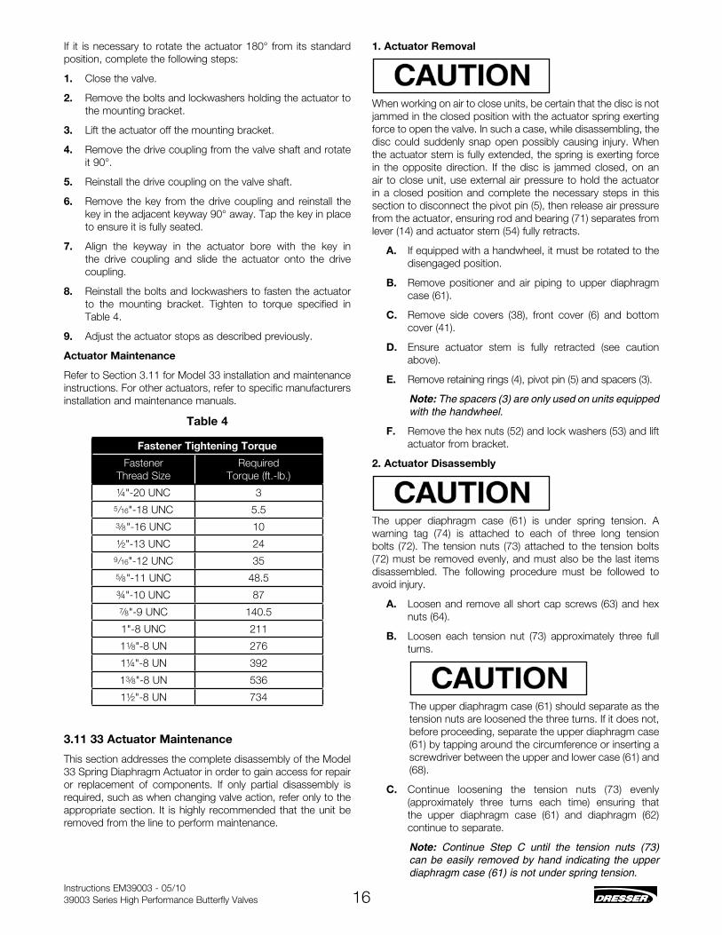
Table 4
Fastener Tightening Torque
Fastener Thread Size
Required Torque (ft.-lb.)
¼"-20 UnC 35/16"-18 UnC 5.53/8"-16 UnC 10
½"-13 UnC 249/16"-12 UnC 355/8"-11 UnC 48.5
¾"-10 UnC 877/8"-9 UnC 140.5
1"-8 UnC 211
11/8"-8 Un 276
1¼"-8 Un 392
13/8"-8 Un 536
1½"-8 Un 734
3.11 33 Actuator Maintenance
This section addresses the complete disassembly of the Model 33 Spring Diaphragm Actuator in order to gain access for repair or replacement of components. If only partial disassembly is required, such as when changing valve action, refer only to the appropriate section. It is highly recommended that the unit be removed from the line to perform maintenance.
1. Actuator Removal
When working on air to close units, be certain that the disc is not jammed in the closed position with the actuator spring exerting force to open the valve. In such a case, while disassembling, the disc could suddenly snap open possibly causing injury. When the actuator stem is fully extended, the spring is exerting force in the opposite direction. If the disc is jammed closed, on an air to close unit, use external air pressure to hold the actuator in a closed position and complete the necessary steps in this section to disconnect the pivot pin (5), then release air pressure from the actuator, ensuring rod and bearing (71) separates from lever (14) and actuator stem (54) fully retracts.
A. If equipped with a handwheel, it must be rotated to the disengaged position.
B. Remove positioner and air piping to upper diaphragm case (61).
C. Remove side covers (38), front cover (6) and bottom cover (41).
D. Ensure actuator stem is fully retracted (see caution above).
E. Remove retaining rings (4), pivot pin (5) and spacers (3).
Note: The spacers (3) are only used on units equipped with the handwheel.
F. Remove the hex nuts (52) and lock washers (53) and lift actuator from bracket.
2. Actuator Disassembly
The upper diaphragm case (61) is under spring tension. A warning tag (74) is attached to each of three long tension bolts (72). The tension nuts (73) attached to the tension bolts (72) must be removed evenly, and must also be the last items disassembled. The following procedure must be followed to avoid injury.
A. Loosen and remove all short cap screws (63) and hex nuts (64).
B. Loosen each tension nut (73) approximately three full turns.
The upper diaphragm case (61) should separate as the tension nuts are loosened the three turns. If it does not, before proceeding, separate the upper diaphragm case (61) by tapping around the circumference or inserting a screwdriver between the upper and lower case (61) and (68).
C. Continue loosening the tension nuts (73) evenly (approximately three turns each time) ensuring that the upper diaphragm case (61) and diaphragm (62) continue to separate.
Note: Continue Step C until the tension nuts (73) can be easily removed by hand indicating the upper diaphragm case (61) is not under spring tension.
Instructions EM39003 - 05/1039003 Series High Performance butterfly Valves 17
D. Remove tension bolts (72) and upper diaphragm case (61).
E. Remove diaphragm/diaphragm plate subassembly from the actuator.
F. Remove retaining clips (57) and push out pin (56). Inspect for damage and/or wear in clevis (55), lever (14), clevis pins (56, 5) and rod end bearing (71). Replace if necessary.
3. Handwheel Removal
A. Rotate handwheel to the disengaged position.
B. Remove bottom cover (41).
C. Remove retaining clips (21) and clevis pin (20).
D. Loosen and remove cap screws (24), lock washers (25) and remove handwheel and bracket subassembly.
4. Handwheel Disassembly
A. Remove pivot pin (26) and remove bracket (23).
B. Remove handwheel subassembly from shaft (22).
C. Remove handwheel shaft subassembly (59). Remove retaining ring (28) then loosen and remove locknut (51).
D. Remove bearing brace (31) and bearing (30).
E. Remove handwheel pivot (27), O-ring (32) and thrust washer (29).
F. Refer to Section 3.13 for reassembly.
5. Body Removal
A. Refer to Section 1 (Actuator Removal) and complete Steps A through E.
B. If the unit is equipped with a handwheel, refer to Section 3 (Handwheel Removal) and complete Steps A through D.
C. Loosen indicator arm (2) by loosening clamp screw (13) and nut (50).
Note: At this time, using ink or a small dab of paint, mark the relative position of the shaft to the lever (14) or mark a line on the lever in line with the slot in the end of the shaft. During reassembly these marks will be used to simplify alignment of the lever on the shaft.
D. Loosen lever cap screw (15).
E. Remove nuts (46), washers (45) and bracket bolts (44), then remove bolts (43).
F. Remove set screw (81) from coupling (79).
G. Separate body subassembly and yoke (10) from bracket (1).
Slide shaft (77) out of yoke.
3.12 Actuator Diaphragm Replacement
The upper diaphragm case (61) is under spring tension. A warning tag (74) is attached to each of three long tension bolts (72). The tension nuts (73) attached to the tension bolts (72) must be removed evenly, and must also be the last items disassembled. The following procedure must be followed to avoid injury.
1. Isolate the valve, vent process pressure and shut off all electrical signal air and supply lines to the valve.
2. If equipped with a handwheel it must be rotated to the disengaged position.
3. Remove air supply piping to upper diaphragm case (61).
4. Remove side covers (38).
5. Verify actuator stem (54) and rod end (71) are securely connected to lever (14) through pivot pin (5) and retaining clips (4) are in place.
6. Loosen and remove all short cap screws (63) and hex nuts (64) in a criss-cross pattern.
7. Loosen each tension nut (73) approximately three full turns.
The upper diaphragm case (61) should separate as the tension nuts are loosened the three turns. If it does not, before proceeding, separate the upper diaphragm case (61) by tapping it around the circumference or inserting a screwdriver between the upper and lower case (61-68).
8. Continue loosening the tension nuts (73) evenly, approximately three turns each time and ensuring the upper diaphragm case (61) and diaphragm (62) continue to separate.
Note: Continue Step 8 until the tension nuts (73) can be easily removed by hand, which indicates that the upper diaphragm case (61) is no longer under spring tension.
8. Remove tension bolts (72) and upper diaphragm case (61).
9. Remove diaphragm.
10. Clean all mating/sealing surfaces which will come in contact, diaphragm (62), and diaphragm plate (65).
11. Install diaphragm (62) on diaphragm plate (65). Align bolt holes with holes in lower case (68).
12. Determine correct orientation for air inlet and replace upper diaphragm case (61).
13. Install three tension bolts (72) with warning plates (74) into upper case (61). Ensure bolts are spaced at 120° to each other.
14. Mount upper case (61) on diaphragm plate (65) such that tension bolts pass through holes in diaphragm (62) and lower case (68).
15. Install tension nuts (73) finger tight onto tension bolts (72).
16. Tighten each tension nut (73) three turns before proceeding

Instructions EM39003 - 05/1039003 Series High Performance butterfly Valves 18
to the next to ensure actuator spring (67) is evenly loaded. Continue until the diaphragm is firmly sandwiched between the flanges of the upper and lower diaphragm cases. Torque tighten tension bolts to 50 in. lb.
17. Install cap screws (63) and nuts (64). Torque tighten to 50 in. lb. in a criss-cross pattern. As this will tend to unload the tension bolts (72) repeat torque tightening of tension bolts and cap screws (63) to 50 in. lb. in a criss-cross pattern until joint is evenly loaded to specified torque values.
18. Reconnect air supply.
19. Stroke actuator to confirm operation.
3.13 33 Actuator Reassembly
1. Actuator Reassembly
A. Replace spring (67) into lower diaphragm case (68).
B. Replace locknut (70) on rod end bearing (71) and screw rod end bearing into actuator stem (54).
C. Replace actuator stem (54) into clevis (55).
D. Replace clevis pin (56) and secure with cap screws (58). Install clevis pin (56) and clips (57).
E. Refer to Section 3.12 and complete Steps 12 through 20.
2. Reassembly of Yoke and Bracket to Valve
A. Install ball bearing (9) into yoke (10).
B. Mount intermediate bracket (1) to yoke (10) with bolts (44), nuts (46), and lockwashers (45). Tighten to appropriate torque value per Table 4.
C. Install bearing (76) into yoke (if applicable).
D. Determine the required actuator action (air to close or air to open). Refer to the proper figure (Figure 19 to open, Figure 20 to close). To obtain proper alignment, the lever must be oriented on the shaft so that the slot in the end of the shaft and arrows or indicator lines are aligned as shown. The distance between the top of the yoke and the top of the pivot pin must be as shown. If the valve is equipped with a handwheel, proceed to step E. Slide shaft (77) through intermediate bracket (item 1 of Figure 15) and partially into yoke (1). With other hand, hold lever (14) and align with the shaft (77) in the desired orientation, slide shaft through lever.
E. If the valve is equipped with a handwheel, the lever consists of two separate arms that are a matched pair and the handwheel lever (refer to view c-c of Figure 17). Slide shaft (77) through intermediate bracket (item 1 of Figure 15) and partially into yoke. The sequence of assembly is to place one lever (item 4 of Figure 17) over the shaft (77) in the correct orientation (per Step D). Slide handwheel lever arm (18) onto shaft. Insert pin (17) and slide second lever arm over shaft in the same orientation as the first lever.
F. Slide indicator (item 2 as indicated in Figure 15) loosely over top of shaft (do not tighten clamp screw at this time). Then continue to slide shaft into yoke until step on shaft (77) contacts ball bearing (9) (as indicated in Figure 15).
G. Install woodruff key (80) in shaft (77). Align key (80) in
shaft (77) with keyway in coupling then slide coupling onto shaft (77).
H. Install key into valve shaft.
I. Move valve to closed position. Rotate valve to required orientation, slide valve shaft through intermediate bracket. Aligning keyway in coupling with valve key, slide valve shaft into coupling (79). Tighten set screw (81).
J. Connect valve body to bracket using cap screws (43) and lockwashers. Tighten to appropriate torque value per Table 4.
3. Reassembly of Actuator to Yoke
With the valve body assembled to the bracket, determine action desired and proceed as follows:
A. Ensure stop (69) is in place in the actuator.
B. Replace the actuator on the bracket in the appropriate hole for desired action and ensure that the rod end bearing (71) is straddled by the lever (14) (or levers if handwheel is supplied).
C. Replace lock washers (53), hex nuts (52) and tighten securely per torque value in Table 4.
D. Rotate the disc to the fully closed position.
E. Depending on the valve action (air to close or air to open), proceed to the appropriate following section for final adjustment.
4. Air to Close
A. Rotate the disc to fully closed position.
B. Attach a temporary air supply line to the actuator and apply 20 psi of air pressure ensuring that when the rod end bearing (71) extends, it is straddled by the lever (14) (or levers if handwheel is supplied).
C. Align the hole in the rod end bearing (71) with the hole in the lever (14) by rotating the actuator stem (54) in the proper direction.
D. Install pivot pin (5) and retaining rings (4).
Note: If the unit is equipped with a handwheel, spacers (3) must be installed on each side of the rod end bearing (71).
E. Tighten hex nut (70) against the actuator stem (54).
F. Ensure lever (14) is vertically aligned with the rod end bearing and stem assembly and tighten lever cap screw (15).
Note: On units equipped with a handwheel, ensure both levers are as close together as possible and in vertical alignment with the rod end bearing and actuator stem, then tighten cap screws (15).
G. With 20 psi of air pressure still on the actuator, rotate the actuator stem (54) to back off the disc so that the flat face of the disc is parallel to the face of the retaining ring.
H. Relieve air pressure and remove temporary air line.
I. Replace front cover (6).
J. Rotate the indicator arm (2) to indicate open position

Instructions EM39003 - 05/1039003 Series High Performance butterfly Valves 19
and secure in place by tightening clamp screw (13) and nut (50).
K. If the unit is equipped with a handwheel, proceed to Section 7 (Handwheel to bracket Assembly).
L. Replace bottom cover (41), side cover (38) and boss cover (42).
5. Air to Open
A. With the disc in the fully closed position, align the hole in the rod end bearing (71) with the hole in the lever (14) by rotating the actuator stem (54) in the proper direction.
B. Install pivot pin (5) and retaining rings (4).
Note: On units equipped with a handwheel, spacers (3) must also be installed on either side of the rod end bearing.
C. Ensure that the lever (14), rod end bearing, and actuator shaft are vertically aligned and tighten cap screw (15).
Note: On units equipped with a handwheel, ensure that both levers are in vertical alignment with the rod end gearing and actuator stem. Then tighten cap screws (15).
D. Rotate the actuator stem (54) to back off the disc so that the flat face of the disc is parallel to the face of the retaining ring.
E. Tighten hex nut (70) against the actuator stem (54).
F. Replace front cover (6).
G. Rotate indicator arm to indicate position on the valve and secure in place by tightening clamp screw (13) and nut (50).
H. If the unit is equipped with a handwheel proceed to Section 7 below for handwheel to bracket assembly.
I. Replace bottom cover (41), side covers (38) and boss cover (42).
6. Handwheel Reassembly
To reassemble handwheel, proceed as follows:
A. Install O-ring (32) in the groove.
Note: Do not lubricate O-Ring.
B. Replace thrust washer (29) and handwheel pivot (27).
Note: The handwheel pivot is installed so that the recessed end is away from the thrust washer as shown in Figure 13.
C. Apply a liberal amount of lubricant to the bearing race (31) and bearing (30) and install ensuring there is one race on either side of the bearing.
D. Install locknut (51) and finger tighten only.
E. Install retaining ring (28).
7. Handwheel to Bracket Assembly
The handwheel is always installed on the same side of the bracket as the actuator. To install the handwheel assembly proceed as follows:
A. Insert handwheel shaft (22) through appropriate bracket
hole and onto lever arm (18) and install clevis pin (20) and retaining clips (21).
B. Install handwheel bracket (23), lock washers (25) and cap screws (24) and tighten firmly.
C. Rotate the handwheel subassembly onto the shaft (22) far enough to allow alignment of the holes in the handwheel pivot (27) to align with the holes in the handwheel bracket (23) and install pivot pins (26) and tighten firmly.
D. Connect handwheel shaft S/A (59) to handwheel.
E. Rotate the handwheel to the disengaged position.
Note: The disengaged position is achieved when the handwheel shaft is fully visible in the slot on the end of the handwheel.
F. Install end cap (33).
G. Replace bottom cover (41), side covers (38) and boss cover (42).
8. Minor Adjustments
In some instances it may be required to shorten or lengthen the rod end bearing (71) to obtain the shutoff desired. The flat face of the disc must be parallel to the face of the retaining ring in the closed position. To adjust the rod end bearing length, refer to Figure 15. Remove one retainer (4) and slide out pivot pin (5) from lever (14). Pull or push rod end bearing out of retainer. Loosen hex nut (70). Rotate rod end to achieve desired length. Tighten hex nut. Align hole in lever (14) with hole in rod end bearing (71). Insert pivot pin (5) through lever and rod end bearing. Install retainer (4). Stroke valve and repeat above steps until desired shutoff is achieved.
Extension of the rod end bearing is limited to approximately 3/8" using this method for adjustment. Further extension could prevent sufficient thread engagement for satisfactory performance. Should more than 3/8" be required, lever (14) is not on the correct shaft spline; refer to appropriate section of this instruction and change as required.

Instructions EM39003 - 05/1039003 Series High Performance butterfly Valves 20
61 Upper Diaphragm Case
62 Diaphragm63 Cap Screw64 Hex nut65 Diaphragm Plate66 Spring guide67 Spring68 Lower Case69 Stop70 Hex nut71 Rod End bearing72 Tension bolt73 Tension nut74 Warning Plate75 Information Plate76 bearing77 Shaft78 Roll Pin79 Coupling80 Woodruff key81 Set Screw
Ref. No.
Description
1 bracket2 Indicator Arm3 Spacer4 Retainer5 Pivot Pin6 Front Cover7 Shaft Cover8 Shaft Cover Screw9 bearing10 yoke11 guide12 Cover13 Clamp Screw14 Lever15 Cap Screw16 Lock Washer17 Lever Arm Pin18 Lever Arm19 Lever Arm bearing20 Clevis Pin21 Retaining Clips22 H/W Shaft S/A23 Handwheel bracket24 Cap Screw25 Lock Washer26 Pivot Pin27 Handwheel Pivot28 Retaining Ring29 Thrust Washer (H/W)30 needle bearing31 bearing Race32 O-Ring33 End Cap34 Handwheel Plate35 H/W Plate Screw36 Handwheel37 Indicator Dot 38 Side Cover39 Serial Plate40 Drive Screw41 bottom Cover42 boss Cover43 bonnet bolt
Ref. No.
Description
44 bracket bolt45 Lock Washer46 nut47 H/W Stop bracket48 Cap Screw
48A Cap Screw49 Stop bolt
49A Locknut50 nut51 Locknut52 nut53 Lock Washer54 Actuator Stem55 Clevis56 Clevis Pin57 Clip58 button Head
Cap Screw59 Handwheel Shaft S/A
59A Handwheel Stop59b Cap Screw59C SpacerRef. No.
Description
3.14 Actuator Parts List
Figure 13

Instructions EM39003 - 05/1039003 Series High Performance butterfly Valves 21
Section B-BFigure 14
Figure 15
Figure 16View C-CFigure 17
Section A-A

Instructions EM39003 - 05/1039003 Series High Performance butterfly Valves 22
Figure 19 Figure 20
Figure 18
Figure 21

Instructions EM39003 - 05/1039003 Series High Performance butterfly Valves 23
Notes

Instructions EM39003 - 05/1039003 Series High Performance butterfly Valves 24
Notes

Instructions EM39003 - 05/1039003 Series High Performance butterfly Valves 25
Notes

EM39003 05/10
www.dresser.com© 2010 Dresser, Inc. All rights reserved.
BELGIUMPhone: +32-2-344-0970Fax: +32-2-344-1123
BRAZILPhone: +55-11-2146-3600Fax: +55-11-2146-3610
CANADAOntarioPhone: +905-335-3529Fax: +905-336-7628
CHINAPhone: +86-10-8486-4515Fax: +86-10-8486-5305
FRANCECourbevoiePhone: +33-1-4904-9000Fax: +33-1-4904-9010
GERMANYViersenPhone: +49-2162-8170-0Fax: +49-2162-8170-280
INDIAMumbaiPhone: +91-22- 8354790Fax: +91-22-8354791New DelhiPhone: +91-11-2-6164175Fax: +91-11-5-1659635
ITALYPhone: +39-081-7892-111Fax: +39-081-7892-208
JAPANChiba Phone: +81-43-297-9222Fax: +81-43-299-1115
KOREAPhone: +82-2-2274-0748Fax: +82-2-2274-0794
MALAYSIAPhone: +60-3-2161-0322Fax: +60-3-2163-6312
MEXICOPhone: +52-5-310-9863Fax: +52-5-310-5584
THE NETHERLANDSPhone: +0031-15-3808666Fax: +0031-18-1641438
RUSSIAVeliky NovgorodPhone: +7-8162-55-7898Fax: +7-8162-55-7921MoscowPhone: +7 495-585-1276Fax: +7 495-585-1279
SAUDI ARABIAPhone: +966-3-341-0278Fax: +966-3-341-7624
SINGAPOREPhone: +65-6861-6100Fax: +65-6861-7172
SOUTH AFRICAPhone: +27-11-452-1550Fax: +27-11-452-6542
SOUTH & CENTRAL AMERICA AND THE CARIBBEANPhone: +55-12-2134-1201Fax: +55-12-2134-1238
SPAINPhone: +34-93-652-6430Fax: +34-93-652-6444
UNITED ARAB EMIRATESPhone: +971-4-8139-200Fax: +971-4-8838-038
UNITED KINGDOMWooburn GreenPhone: +44-1628-536300Fax: +44-1628-536319
UNITED STATESMassachusettsPhone: +1-508-586-4600Fax: +1-508-427-8971Corpus Christi, Texas Phone: +1-361-881-8182Fax: +1-361-881-8246Dresser DirectDeer Park, TexasPhone: +1-281-884-1000Fax: +1-281-884-1010Dresser Flow TechnologiesHouston, TexasPhone: +1-281-671-1640Fax: +1-281-671-1735CaliforniaPhone: +1-562-941-7610Fax: +1-562-941-7810
DIRECT SALES OFFICE LOCATIONS
Dresser Masoneilan Dresser, Inc., Flow Technologies 10343 Sam Houston Park Drive Houston, Texas 77064 U.S.AT. +1-281-671-1640F. +1-281-671-1735E. [email protected]
About Dresser, Inc.Dresser Inc. is a global leader in providing highly-engineered
infrastructure products for the global energy industry.
Leading brand names within the Dresser portfolio include
Dresser Wayne® retail fueling systems, Waukesha®
natural gas-fired engines, Masoneilan® control valves,
Consolidated® pressure relief valves, and ROOTS®
blowers and rotary gas meters. The company has
manufacturing and customer service facilities strategically
located worldwide and a sales presence in more than 150
countries. www.dresser.com.
About Dresser MasoneilanDresser Masoneilan, headquartered in Houston, Texas, has
been the leading global partner in process control valves
and solutions for more than 100 years. A business segment
of Dresser, Inc., the company delivers customized products,
services and diagnostic solutions for oil and gas, process
and power generation applications. www.dresser.com