instruction manual for arc welding machine - home - cebora … · 2017-11-30 · sory art. 193. f -...
TRANSCRIPT
10
IMPORTANT: BEFORE STARTING THE EQUIPMENT,READ THE CONTENTS OF THIS MANUAL, WHICH MUSTBE STORED IN A PLACE FAMILIAR TO ALL USERS FORTHE ENTIRE OPERATIVE LIFE-SPAN OF THE MACHINE.THIS EQUIPMENT MUST BE USED SOLELY FOR WELD-ING OPERATIONS.
1 SAFETY PRECAUTIONS
WELDING AND ARC CUTTING CAN BEHARMFUL TO YOURSELF AND OTHERS.The user must therefore be educated
against the hazards, summarized below, deriving from weld-ing operations. For more detailed information, order themanual code 3.300.758
NOISEThis machine does not directly produce noiseexceeding 80dB. The plasma cutting/welding proce-dure may produce noise levels beyond said limit;
users must therefore implement all precautions required bylaw.
ELECTRIC AND MAGNETIC FIELDS - May be dangerous.· Electric current following through any conduc-tor causes localized Electric and MagneticFields (EMF). Welding/cutting current createsEMF fields around cables and power sources.· The magnetic fields created by high currents
may affect the operation of pacemakers. Wearers of vitalelectronic equipment (pacemakers) shall consult their physi-cian before beginning any arc welding, cutting, gouging orspot welding operations.· Exposure to EMF fields in welding/cutting may have otherhealth effects which are now not known.· All operators should use the followingprocedures in order tominimize exposure to EMF fields from the welding/cutting cir-cuit:
- Route the electrode and work cables together - Securethem with tape when possible.
- Never coil the electrode/torch lead around your body.- Do not place your body between the electrode/torch
lead and work cables. If the electrode/torch lead cable ison your right side, the work cable should also be on yourright side.
- Connect the work cable to the workpiece as close as possible to the area being welded/cut.
- Do not work next to welding/cutting power source.
EXPLOSIONS· Do not weld in the vicinity of containers under pres-sure, or in the presence of explosive dust, gases orfumes. · All cylinders and pressure regulators used in
welding operations should be handled with care.
ELECTROMAGNETIC COMPATIBILITYThis machine is manufactured in compliance with theinstructions contained in the standard IEC 60974-10 (CL. A),and must be used solely for professional purposes in anindustrial environment. There may be potential difficul-ties in ensuring electromagnetic compatibility in non-industrial environments.
DISPOSAL OF ELECTRICAL AND ELECTRONIC EQUIPMENTDo not dispose of electrical equipment togetherwith normal waste!In observance of European
Directive 2002/96/EC on Waste Electrical and ElectronicEquipment and its implementation in accordance withnational law, electrical equipment that has reached theend of its life must be collected separately and returnedto an environmentally compatible recycling facility. As theowner of the equipment, you should get information onapproved collection systems from our local representa-tive. By applying this European Directive you will improvethe environment and human health!
IN CASE OF MALFUNCTIONS, REQUEST ASSISTANCEFROM QUALIFIED PERSONNEL.
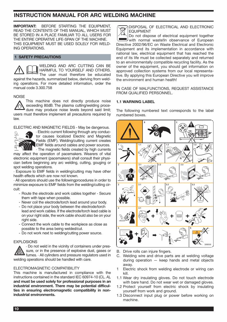
1.1 WARNING LABEL
The following numbered text corresponds to the labelnumbered boxes.
B. Drive rolls can injure fingers. C. Welding wire and drive parts are at welding voltage
during operation — keep hands and metal objectsaway.
1 Electric shock from welding electrode or wiring cankill.
1.1 Wear dry insulating gloves. Do not touch electrodewith bare hand. Do not wear wet or damaged gloves.
1.2 Protect yourself from electric shock by insulatingyourself from work and ground.
1.3 Disconnect input plug or power before working onmachine.
INSTRUCTION MANUAL FOR ARC WELDING MACHINE
11
2 Breathing welding fumes can be hazardous to yourhealth.
2.1 Keep your head out of fumes. 2.2 Use forced ventilation or local exhaust to remove
fumes. 2.3 Use ventilating fan to remove fumes. 3 Welding sparks can cause explosion or fire.3.1 Keep flammable materials away from welding. 3.2 Welding sparks can cause fires. Have a fire extin-
guisher nearby and have a watchperson ready to useit.
3.3 Do not weld on drums or any closed containers. 4 Arc rays can burn eyes and injure skin. 4.1 Wear hat and safety glasses. Use ear protection and
button shirt collar. Use welding helmet with correctshade of filter. Wear complete body protection.
5 Become trained and read the instructions beforeworking on the machine or welding.
6 Do not remove or paint over (cover) label.
2 GENERAL DESCRIPTIONS
2.1 SPECIFICATIONS
This welding machine is a constant current power sourcebuilt using INVERTER technology, designed to weld coveredelectrodes (not including cellulosic) and for TIG procedures,with contact starting and high frequency.IT MUST NOT BE USED TO DEFROST PIPES.
2.2 EXPLANATION OF THE TECHNICAL SPECIFI-CATIONS LISTED ON THE MACHINE PLATE.
This machine is manufactured according to the followinginternational standards: IEC 60974.1 - IEC 60974.3 -IEC 60974.10 CL. A - IEC 61000-3-11 - 61000-3-12 (seenote 2).N°. Serial number, which must be indicated on any
type of request regarding the welding machine. Three phase static transformer-rectifier frequency converter.Drooping-characteristic.
MMA Suitable for welding with covered electrodes.TIG Suitable for TIG welding.U0. Secondary open-circuit voltage X. Duty cycle percentage. % of 10 minutes during
which the welding machine may run at a certain current without overheating.
I2. Welding currentU2. Secondary voltage with current I2U1. Rated supply voltage
The machine has an automatic supply voltage selector.
3~ 50/60Hz 50- or 60-Hz three-phase power supplyI1 max. This is the maximum value of the absorbed current.I1 eff. This is the maximum value of the actual current
absorbed, considering the duty cycle.IP23S Protection rating for the housing.
Grade 3 as the second digit means that this equipment may be stored, but it is not suitable for use outdoors in the rain, unless it is protected.Suitable for hazardous environments.S
Note:1- The machine has also been designed for use in envi-
ronments with a pollution rating of 1. (See IEC 60664).2- This equipment complies with IEC 61000-3-12 provided
that the maximum permissible system impedance ZMAXis less than or equal to 0,117(Art. 362) - 0,137 (Art. 360)at the interface point between the user's supply and thepublic system. It is the responsibility of the installer oruser of the equipment to ensure, by consultation with thedistribution network operator if necessary, that the equip-ment is connected only to a supply with maximum per-missible system impedance ZMAX less than or equal to0,117(Art. 362) - 0,137 (Art. 360).
2.3 DESCRIPTION OF PROTECTIVE DEVICES
2.3.1. Thermal protectionThis machine is protected by a temperature probe, whichprevents the machine from operating if the allowable tem-peratures are exceeded. Under these conditions the fankeeps running and the LED M lights.2.3.2 - Block protection art. 338
This welding machine is equipped with various safetydevices that stop the machine before it can suffer damage.The welding machine may operate within the following volt-age ranges: For rated voltage 208/220/230V, from 175 to 270VFor rated voltage 400/440V, from 340 to 490VCaution: if the supply voltage does not fall between theabove values, no LED will light and the fan is powered.If the phases are not properly connected, 3 light points willappear (steadily lit) on the display P when the machine isstarted.If, with the machine on, the voltage falls below 175 V (U1 =230V) or 340 V (U1 = 400V), the display P will show theabbreviation E3.If, with the machine on, the voltage rises above 275 V (U1 =230V) or 490 V (U1 = 400V), the display P shows the abbre-viation E4.In this case turn off the machine, restore the proper voltageand restart. If the problem has been corrected, the weldingmachine will begin operating again.If, with the machine on, the display P shows the message E2or E1, check the supply voltage of the machine; if it is cor-rect, the machine requires technical service.If a low water level is detected for the cooling unit theabbreviation H2O flashes on the display P.
3 INSTALLATION
Make sure that the supply voltage matches the voltage indi-cated on the specifications plate of the welding machine.When mounting a plug, make sure it has an adequatecapacity, and that the yellow/green conductor of the powersupply cable is connected to the earth pin.The capacity of the overload cutout switch or fuses installedin series with the power supply must be equivalent to theabsorbed current I1 of the machine.WARNING! Extension cords of up to 30m must have across-section of at least 2.5 mm2.
12
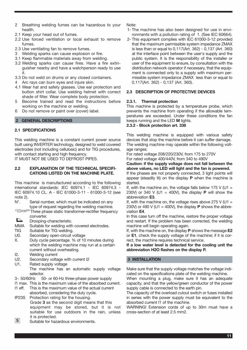
3.1 START-UP
Only skilled personnel should install the machine. All con-nections must be carried out according to current regula-tions, and in full observance of safety laws.
3.2 DESCRIPTION OF THE EQUIPMENT
AL - Process selector switch This button is used to choose the welding process
(MMA or TIG). The selection changes each time it is pressed.The LEDs light alongside the various symbols to display yourchoice.
B - MMA welding LED This machine can weld all types of coated electrodes exceptcellulosic. With this process the current is adjusted using theknob O, and it is possible to adjust the "arc force" (LED AN)and "hot start" function (LED AM).
AH - Continuous TIG welding LED
AI - Pulsed TIG welding LED The pulse frequency is adjustable from 0.16 to 500Hz (LED
T), the peak current and the base current may be activatedvia the LEDs X and W, respectively, and are adjustable usingthe knob O.From a pulse frequency of 0.16 to 1.1 Hz, the display P alter-nates displaying the peak current (main) and the base cur-rent. The LEDs X and W light alternately; beyond 1.1 Hz thedisplay P displays the mean of the two currents and theLEDs X and W both remain lit.
A - Mode selector switchThe selection changes each time it is pressed, and is
displayed by lighting the LED C or D together with otherLEDs displaying the welding mode.
C - Arc starting without high frequency LED.To light the arc, press the torch trigger, touch the workpiecewith the tungsten electrode, and lift it again. This move mustbe quick and decisive.
D - Arc starting with high frequency LED.To light the arc, press the torch trigger: a high voltage/fre-quency pilot spark will light the arc.
AH
AI
G
A
AL
Y
Z
AAAA
AB
W
V
Y
AB
UTSAOANAMRQ
B
C E F D H I L M P AP O X N
ZFig. 1
13
E - 2-stage TIG welding LED (manual)When the torch trigger is pressed, the current begins toincrease over the previously set "slope up" time, until itreaches the value set by means of the knob O. When thetrigger is released, the current begins to drop over the previ-ously set "SLOPE DOWN" time, until it returns to zero.In this position, you may connect the pedal control acces-sory ART. 193.
F - 4-stage TIG welding LED (automatic)This program differs from the previous one in that the arc isboth started and shut off by pressing and releasing the torchtrigger.
G - four-stage TIG welding LED with dual cur-rent level, (automatic).Set the two current levels before lighting the arc:First level: press the R key until the LED X lights, and adjustthe main current using the knob O.Second level: press the R key until the LED W lights, andadjust the main current using the knob O. When the torch trigger is pressed, the current begins toincrease over the previously set "slope up" time (led S lit),until it reaches the value set by means of the knob O. TheLED X lights and appears on the display P.Should it be necessary to reduce the current during welding,without shutting of the arc (for instance when changing thewelding material or working position, moving from horizontalto upright, etc.…), press and immediately release the torchtrigger: the current will switch to the second value selected,the LED W will light and X will go off.To return to the previous main current, press and release thetorch trigger once again. The LED X will light, and the LED Wwill go off. To stop welding at any time, simply hold down thetorch trigger for more than 0.7 seconds, then release. Thecurrent begins to fall to zero within the previously set "slopedown" time interval (LED U lit).If you press and immediately release the torch trigger duringthe "slope down" phase, you will return to "slope up" if it is setto greater than zero, or to the lesser current value of those set.NOTE: The expression "PRESS AND IMMEDIATELYRELEASE" refers to a maximum time of 0.5 seconds.
H - four-stage TIG welding LED with three lev-els of current (automatic).To set the three minimum welding currents, proceed as fol-lows:Press the selector switch R until the LED X lights, then adjustthe maximum current value using the knob O.Press the selector switch R until the LED W lights, thenadjust the intermediate current value using the knob O.Press the selector switch R until the LED AP lights, thenadjust the starting current value using the knob O.The operating logic is the same as previously described forwelding with dual current level (LED G).
I - special program LED To light the arc, press the torch trigger and hold it down; thecurrent begins to increase at a fixed rate. If the torch triggeris released, the current immediately rises to the weldingvalue (LED X). To stop welding, press the torch trigger andhold it down; the current begins to drop at a fixed rate. Thecurrent immediately returns to zero if the trigger is released.
L - spot-welding LED (Manual).After selecting the welding current (LED X) and the spotwelding time (LED T) using the selector switch R, set the val-ues using the knob O.This welding mode is to be used only if start-up with high fre-quency is selected (LED D lit). In this welding mode, theoperator presses the torch trigger, the arc lights, and afterthe set spot welding time the arc shuts off automatically. Todo the next spot, you must therefore release the torch trig-ger and press it again.
M - LED - THERMAL PROTECTIONLights when the operator exceeds the duty cycle or per-centage intermittence admissible for the machine, andsimultaneously blocks the current output.NOTE: In this condition the fan continues cooling thepower source.
O - Knob Normally adjusts the welding current.Also, if you select a function with the selector switch
R, this knob adjusts its size.
P - Display Displays the welding current and the settingsselected by means of the push-button R and
adjusted via the knob O.In the machine blocking procedures (see 2.3.2), it displays:Three flashing or steadily lit pointsThe abbreviations E1 E2 E3 E4The abbreviation H20
N - Display Normally displays the arc voltage in relation tothe current welding process.
When setting the cooling unit operation, it displays the sta-tus of the unit.
Q - SELECTOR Selects and saves programs.The welding machine can save nine welding pro-
grams P01…..P09, and call them up using this button. Aworking program PL is also available. SelectingWhen this push-button is pressed briefly, the display Pshows the next program number after the one being workedon. If it has not been saved the message will flash, otherwiseit will remain steady.SavingOnce the program has been selected, hold for more than 3seconds to save the data. In confirmation, the program num-ber on the display P will stop flashing
R - SELECTOR When this button is pressed, the LEDs light in suc-cession:
Warning: only those LEDs that refer to the chosen weldingmode will light; i.e., in continuous TIG welding the LED T,representing the pulse frequency, will not light.Each LED indicates the parameter that may be adjusted bymeans of the knob O while the LED itself is lit. Five secondsafter the last variation, the LED involved will shut off; themain welding current will be displayed, and the correspond-ing LED X lights.
14
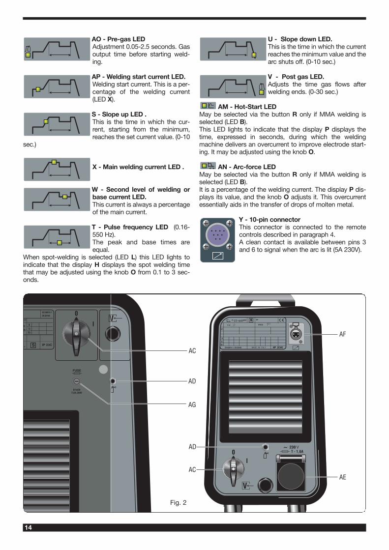
AO - Pre-gas LEDAdjustment 0.05-2.5 seconds. Gasoutput time before starting weld-ing.
AP - Welding start current LED.Welding start current. This is a per-centage of the welding current(LED X).
S - Slope up LED .This is the time in which the cur-rent, starting from the minimum,reaches the set current value. (0-10
sec.)
X - Main welding current LED .
W - Second level of welding orbase current LED. This current is always a percentageof the main current.
T - Pulse frequency LED (0.16-550 Hz). The peak and base times areequal.
When spot-welding is selected (LED L) this LED lights toindicate that the display H displays the spot welding timethat may be adjusted using the knob O from 0.1 to 3 sec-onds.
U - Slope down LED.This is the time in which the currentreaches the minimum value and thearc shuts off. (0-10 sec.)
V - Post gas LED.Adjusts the time gas flows afterwelding ends. (0-30 sec.)
AM - Hot-Start LED May be selected via the button R only if MMA welding isselected (LED B).This LED lights to indicate that the display P displays thetime, expressed in seconds, during which the weldingmachine delivers an overcurrent to improve electrode start-ing. It may be adjusted using the knob O.
AN - Arc-force LEDMay be selected via the button R only if MMA welding isselected (LED B).It is a percentage of the welding current. The display P dis-plays its value, and the knob O adjusts it. This overcurrentessentially aids in the transfer of drops of molten metal.
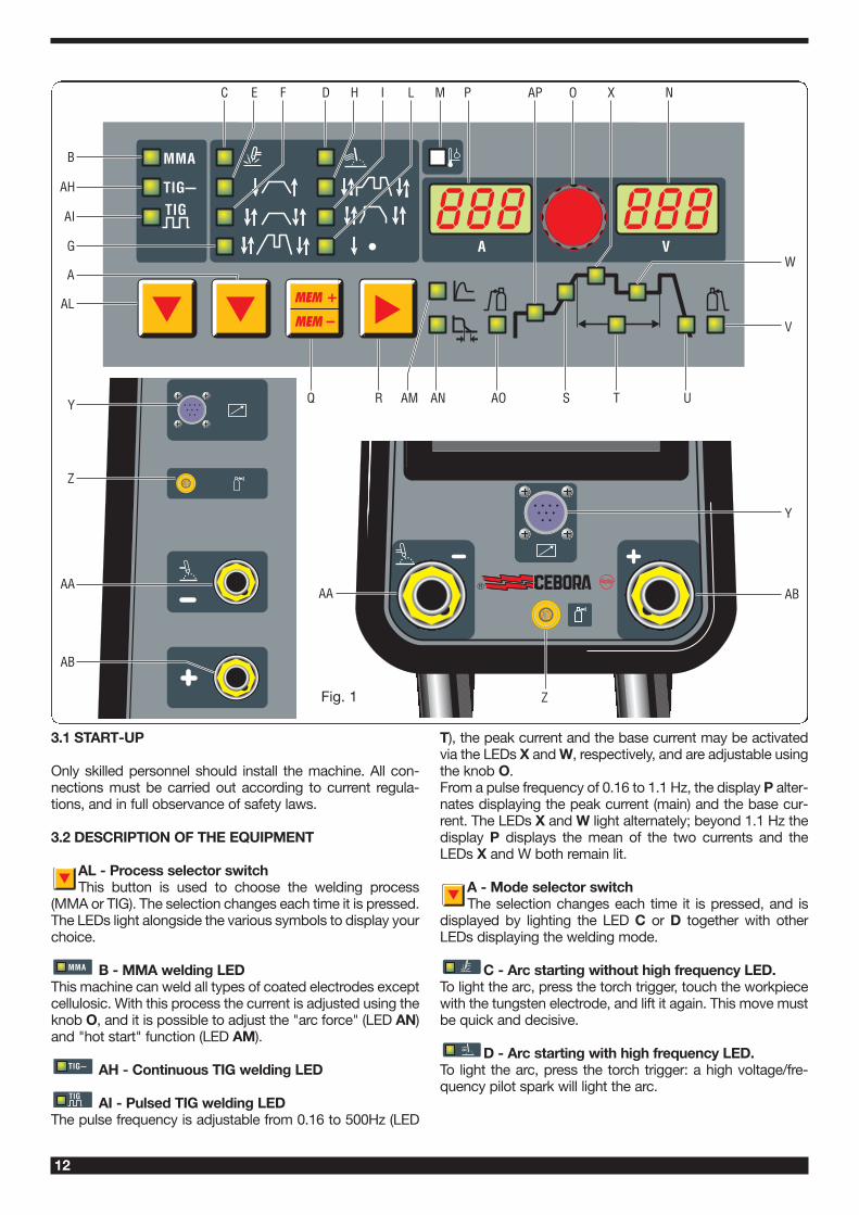
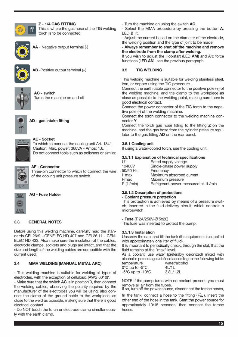
Y - 10-pin connectorThis connector is connected to the remotecontrols described in paragraph 4.A clean contact is available between pins 3and 6 to signal when the arc is lit (5A 230V).
AF
AE
AD
AC
AC
AD
AG
Fig. 2
15
Z - 1/4 GAS FITTINGThis is where the gas hose of the TIG weldingtorch is to be connected.
AA - Negative output terminal (-)
AB -Positive output terminal (+)
AC - switchTurns the machine on and off
AD - gas intake fitting
AE - Socket To which to connect the cooling unit Art. 1341 Caution: Max. power: 360VA - Amps: 1.6. Do not connect tools such as polishers or similar.
AF - Connector Three-pin connector to which to connect the wireof the cooling unit pressure switch.
AG - Fuse Holder
3.3. GENERAL NOTES
Before using this welding machine, carefully read the stan-dards CEI 26/9 - CENELEC HD 407 and CEI 26.11 - CEN-ELEC HD 433. Also make sure the insulation of the cables,electrode clamps, sockets and plugs are intact, and that thesize and length of the welding cables are compatible with thecurrent used.
3.4 MMA WELDING (MANUAL METAL ARC)
- This welding machine is suitable for welding all types ofelectrodes, with the exception of cellulosic (AWS 6010)*.- Make sure that the switch AC is in position 0, then connectthe welding cables, observing the polarity required by themanufacturer of the electrodes you will be using; also con-nect the clamp of the ground cable to the workpiece, asclose to the weld as possible, making sure that there is goodelectrical contact. - Do NOT touch the torch or electrode clamp simultaneous-ly with the earth clamp.
- Turn the machine on using the switch AC.- Select the MMA procedure by pressing the button A:LED B lit.- Adjust the current based on the diameter of the electrode,the welding position and the type of joint to be made.- Always remember to shut off the machine and removethe electrode from the clamp after welding. If you wish to adjust the Hot-start (LED AM) and Arc forcefunctions (LED AN), see the previous paragraph.
3.5 TIG WELDING
This welding machine is suitable for welding stainless steel,iron, or copper using the TIG procedure.Connect the earth cable connector to the positive pole (+) ofthe welding machine, and the clamp to the workpiece asclose as possible to the welding point, making sure there isgood electrical contact.Connect the power connector of the TIG torch to the nega-tive pole (-) of the welding machine.Connect the torch connector to the welding machine con-nector Y.Connect the torch gas hose fitting to the fitting Z on themachine, and the gas hose from the cylinder pressure regu-lator to the gas fitting AD on the rear panel.
3.5.1 Cooling unit If using a water-cooled torch, use the cooling unit.
3.5.1.1 Explanation of technical specificationsU1 Rated supply voltage1x400V Single-phase power supply50/60 Hz FrequencyI1max Maximum absorbed current Pmax Maximum pressure P (1l/min) Refrigerant power measured at 1L/min
3.5.1.2 Description of protections- Coolant pressure protectionThis protection is achieved by means of a pressure swit-ch, inserted in the fluid delivery circuit, which controls amicroswitch.
- Fuse (T 2A/250V-Ø 5x20)This fuse was inserted to protect the pump.
3.5.1.3 InstallationUnscrew the cap and fill the tank (the equipment is suppliedwith approximately one liter of fluid).It is important to periodically check, through the slot, that thefluid remains at the "max" level.As a coolant, use water (preferably deionized) mixed withalcohol in percentages defined according to the following table:temperature water/alcohol0°C up to -5°C 4L/1L-5°C up to -10°C 3.8L/1.2L
NOTE If the pump turns with no coolant present, you mustremove all air from the tubes.If so, turn off the power source, disconnect the torche hoses,
fill the tank, connect a hose to the fitting ( ), Insert theother end of the hose in the tank. Start the power source forapproximately 10/15 seconds, then connect the torchehoses.
16
Turn on the machine. To select the operating mode of thecooling unit, proceed as follows:1. Select any TIG welding mode.2. Press the key Q and, while holding it down, press the
key R. Keep them pressed until the abbreviation H2O appears on the display P.
3. Select the operating mode using the knob O, keeping inmind that the numbers that appear on the display Nhave the following meaning: 1 = Unit off, 2 = Continuous operation, 3 = Automatic operation.
To exit selection, briefly press the key Q.NOTE: "Automatic mode" means that the cooling unit startswhen the torch button is pressed and stops running approx-imately 2 minutes after the torch button is released.Warning! If MMA electrode welding is selected, cooling is noton and may not be selected. It is normal for the machine displayP to display, on start-up, the flashing abbreviation H2O.
3.5.1.4 Cooling unit for Art. 360If using a water-cooled torch, use the cooling unit.The trolley Art. 1432 is required to position and transport thewelding machine together with the cooling unit.After filling the tank with coolant, connect the plug of themains cable to the socket AE of the welding machine, thenconnect the 3-pin male patch connector to the connector AF.
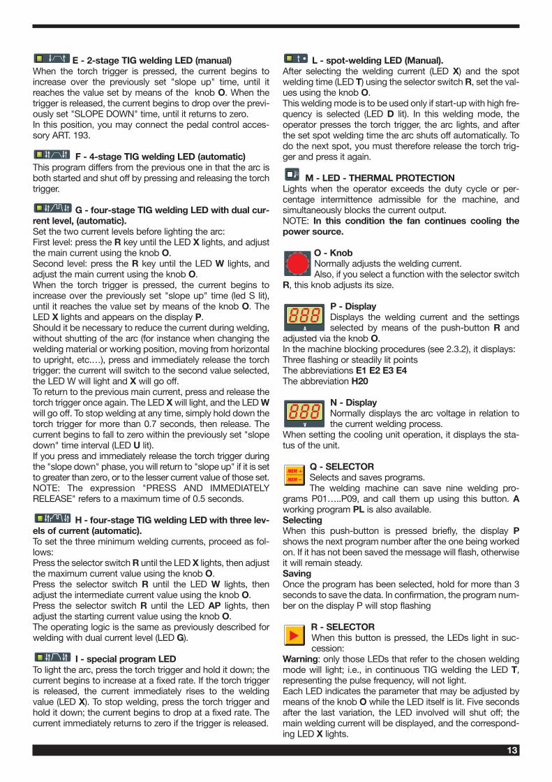
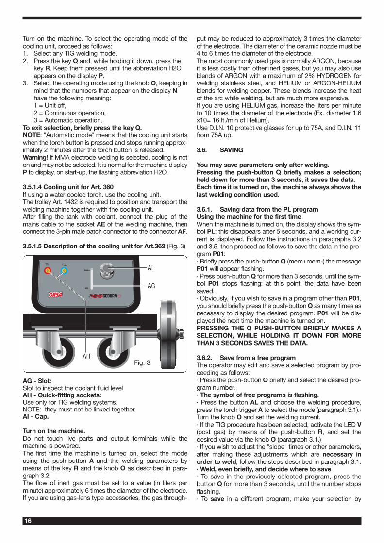
3.5.1.5 Description of the cooling unit for Art.362 (Fig. 3)
AG - Slot:Slot to inspect the coolant fluid levelAH - Quick-fitting sockets:Use only for TIG welding systems.NOTE: they must not be linked together.AI - Cap.
Turn on the machine.Do not touch live parts and output terminals while themachine is powered.The first time the machine is turned on, select the modeusing the push-button A and the welding parameters bymeans of the key R and the knob O as described in para-graph 3.2.The flow of inert gas must be set to a value (in liters perminute) approximately 6 times the diameter of the electrode.If you are using gas-lens type accessories, the gas through-
put may be reduced to approximately 3 times the diameterof the electrode. The diameter of the ceramic nozzle must be4 to 6 times the diameter of the electrode.The most commonly used gas is normally ARGON, becauseit is less costly than other inert gases, but you may also useblends of ARGON with a maximum of 2% HYDROGEN forwelding stainless steel, and HELIUM or ARGON-HELIUMblends for welding copper. These blends increase the heatof the arc while welding, but are much more expensive.If you are using HELIUM gas, increase the liters per minuteto 10 times the diameter of the electrode (Ex. diameter 1.6x10= 16 lt./min of Helium).Use D.I.N. 10 protective glasses for up to 75A, and D.I.N. 11from 75A up.
3.6. SAVING
You may save parameters only after welding.Pressing the push-button Q briefly makes a selection;held down for more than 3 seconds, it saves the data.Each time it is turned on, the machine always shows thelast welding condition used.
3.6.1. Saving data from the PL programUsing the machine for the first timeWhen the machine is turned on, the display shows the sym-bol PL; this disappears after 5 seconds, and a working cur-rent is displayed. Follow the instructions in paragraphs 3.2and 3.5, then proceed as follows to save the data in the pro-gram P01:· Briefly press the push-button Q (mem+mem-) the messageP01 will appear flashing.· Press push-button Q for more than 3 seconds, until the sym-bol P01 stops flashing: at this point, the data have beensaved.· Obviously, if you wish to save in a program other than P01,you should briefly press the push-button Q as many times asnecessary to display the desired program. P01 will be dis-played the next time the machine is turned on.PRESSING THE Q PUSH-BUTTON BRIEFLY MAKES ASELECTION, WHILE HOLDING IT DOWN FOR MORETHAN 3 SECONDS SAVES THE DATA.
3.6.2. Save from a free programThe operator may edit and save a selected program by pro-ceeding as follows:· Press the push-button Q briefly and select the desired pro-gram number.· The symbol of free programs is flashing.· Press the button AL and choose the welding procedure,press the torch trigger A to select the mode (paragraph 3.1).·Turn the knob O and set the welding current.· If the TIG procedure has been selected, activate the LED V(post gas) by means of the push-button R, and set thedesired value via the knob O (paragraph 3.1.)· If you wish to adjust the "slope" times or other parameters,after making these adjustments which are necessary inorder to weld, follow the steps described in paragraph 3.1.· Weld, even briefly, and decide where to save· To save in the previously selected program, press thebutton Q for more than 3 seconds, until the number stopsflashing.· To save in a different program, make your selection by
AH
AI
AG
Fig. 3
17
briefly pressing the push-button Q, then hold down thepush-button Q for more than 3 seconds.
3.6.3 Save from a saved programBeginning with a previously saved program, the operatormay edit the data in memory to update the program itself, orto find new parameters to save in another program.
3.6.3.1 Update· After turning on the machine, select the parameters to beedited and edit them.· Weld, even briefly.· Hold down the Q button for more than 3 seconds, until thesave is confirmed (program symbol changes from flashing tosteady).
3.6.3.2 Save in a new program· After turning on the machine, select the parameters to beedited and edit them.· Weld, even briefly.· Briefly press the selector Q until the desired program is dis-played.· Hold down the Q button until the save is confirmed (pro-gram symbol changes from flashing to steady).
4 REMOTE CONTROLS
The following remote controls may be connected to adjustthe welding current for this welding machine:Art. 1270 TIG torch button only.(air-cooling)Art. 1273 TIG torch button only.(water-cooling)Art. 1266 TIG torch UP/DOWN.(air-cooling)Art. 1274 TIG torch UP/DOWN.(water-cooling)ART. 193 may be used in any TIG welding mode with thisaccessory.Remote controls that include a potentiometer regulatethe welding current from the minimum to the maximumcurrent set via the knob O.Remote controls with UP/DOWN logic regulate thewelding current from the minimum to the maximum.The remote control settings are always active in the PL pro-gram, while they are not active in a saved program.
5 MAINTENANCE
Any maintenance operation must be carried out by qua-lified personnel in compliance with standard CEI 26-29(IEC 60974-4).
5.1 GENERATOR MAINTENANCE
In the case of maintenance inside the machine, makesure that the switch AC is in position "O" and that thepower cord is disconnected from the mains. It is also necessary to periodically clean the interior of themachine from the accumulated metal dust, using com-pressed air.
5.2 PRECAUTIONS AFTER REPAIRS.
After making repairs, take care to organize the wiring so thatthere is secure insulation between the primary and secon-dary sides of the machine. Do not allow the wires to come
into contact with moving parts or those that heat up duringoperation. Reassemble all clamps as they were on the origi-nal machine, to prevent a connection from occurringbetween the primary and secondary circuits should a wireaccidentally break or be disconnected.Also mount the screws with geared washers as on the ori-ginal machine.
94
QUESTA PARTE È DESTINATA ESCLUSIVAMENTE AL PERSONALE QUALIFICATO.
THIS PART IS INTENDED SOLELY FOR QUALIFIED PERSONNEL.
DIESER TEIL IST AUSSCHLIEßLICH FÜR DAS FACHPERSONAL BESTIMMT.
CETTE PARTIE EST DESTINEE EXCLUSIVEMENT AU PERSONNEL QUALIFIE.
ESTA PARTE ESTÁ DESTINADA EXCLUSIVAMENTE AL PERSONAL CUALIFICADO.
ESTA PARTE È DEDICADA EXCLUSIVAMENTE AO PESSOAL QUALIFICADO.
TÄMÄ OSA ON TARKOITETTU AINOASTAAN AMMATTITAITOISELLE HENKILÖKUNNALLE.
DETTE AFSNIT HENVENDER SIG UDELUKKENDE TIL KVALIFICERET PERSONALE.
DIT DEEL IS UITSLUITEND BESTEMD VOOR BEVOEGD PERSONEEL.
DENNA DEL ÄR ENDAST AVSEDD FÖR KVALIFICERAD PERSONAL.
AUTOV TO TMHVMA PROORIVZETAI APOKLEISTIKAV GIA TO EIDIKEUMEVNO PROSWPIKO.V
95
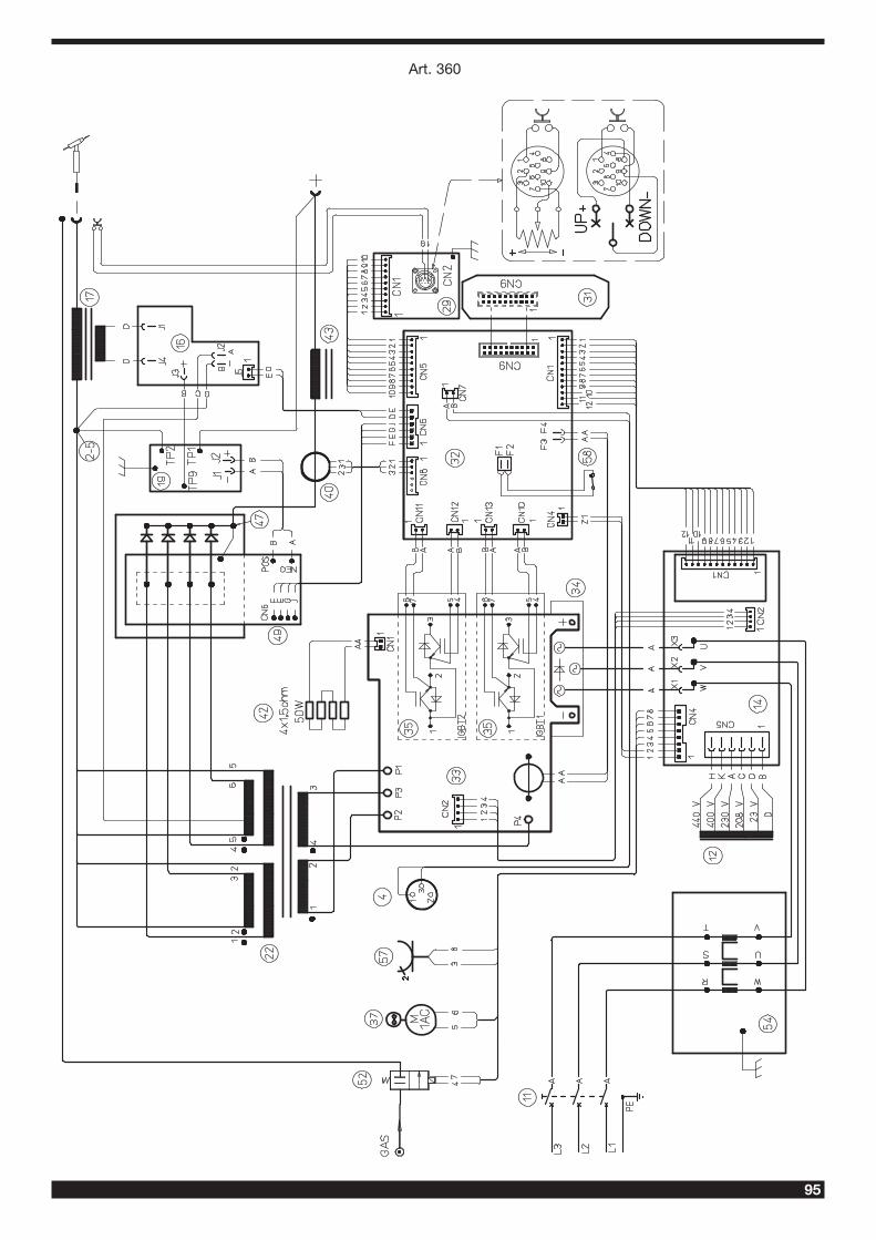
Art. 360
96
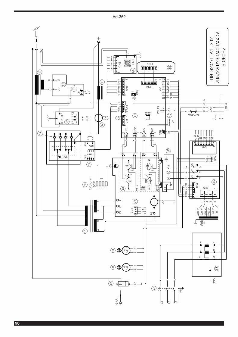
Art.362
97
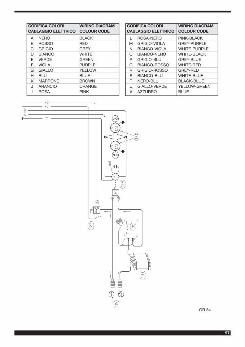
GR 54
CODIFICA COLORI WIRING DIAGRAMCABLAGGIO ELETTRICO COLOUR CODE
A NERO BLACKB ROSSO REDC GRIGIO GREYD BIANCO WHITEE VERDE GREENF VIOLA PURPLEG GIALLO YELLOWH BLU BLUEK MARRONE BROWNJ ARANCIO ORANGEI ROSA PINK
CODIFICA COLORI WIRING DIAGRAMCABLAGGIO ELETTRICO COLOUR CODE
L ROSA-NERO PINK-BLACKM GRIGIO-VIOLA GREY-PURPLEN BIANCO-VIOLA WHITE-PURPLEO BIANCO-NERO WHITE-BLACKP GRIGIO-BLU GREY-BLUEQ BIANCO-ROSSO WHITE-REDR GRIGIO-ROSSO GREY-REDS BIANCO-BLU WHITE-BLUET NERO-BLU BLACK-BLUEU GIALLO-VERDE YELLOW-GREENV AZZURRO BLUE
98
pos DESCRIZIONE DESCRIPTION
01 SUPPORTO MANICO HANDLE SUPPORT
02 MANICO HANDLE
03 COPERCHIO COVER
04 CONNETTORE + CAVO CONNECTOR + CABLE
05 PANNELLO POSTERIORE BACK PANEL
06 CORNICE FRAME
07 PANNELLO ALETTATO FINNED PANEL
08 CAVO RETE POWER CORD
09 PRESSACAVO STRAIN RELIEF
10 PROTEZIONE PROTECTION
11 INTERRUTTORE SWITCH
12 TRASFORMATORE TRANSFORMER
13 LATERALE SIDE PANEL
14 CIRCUITO DI SERVIZIO AUXLIARY CIRCUIT
15 FONDO BOTTOM
16 CIRCUITO ALTA FREQUENZA HIGH-FREQ. CIRCUIT
17 TRASFORMATORE H.F. H.F. TRANSFORMER
18 SUPPORTO SUPPORT
19 CIRCUITO FILTRO FILTER CIRCUIT
20 PIANO INTERMEDIO INSIDE BAFFLE
21 SUPPORTO CENTRALE SEC. SEC CENTRAL SUPPORT
22 TRASFORMAT. DI POTENZA POWER TRANSFORMER
23 RACCORDO A GOMITO UNION ELBOW
24 PANNELLO ANTERIORE FRONT PANEL
25 PRESA GIFAS GIFAS SOCKET
26 RACCORDO FITTING
27 RETE METALLICA WIRE NETTING
28 TAPPO CAP
29 CIRCUITO CONNETTORE CONNECTOR CIRCUIT
pos DESCRIZIONE DESCRIPTION
30 MANOPOLA KNOB
31 CIRCUITO PANNELLO PANEL CIRCUIT
32 CIRCUITO DI CONTROLLO CONTROL CIRCUIT
33 CIRCUITO IGBT. IGBT CIRCUIT
34 RADDRIZZATORE RECTIFIER
35 IGBT IGBT
36 SUPPORTO CENTRALE PRIM. PRIM. CENTRAL SUPPORT
37 MOTORE CON VENTOLA MOTOR WITH FAN
38 DISSIPATORE RADIATOR
39 SUPPORTO TRASDUTTORE TRANSDUCER SUPPORT
40 TRASDUTTORE TRANSDUCER
41 SUPPORTO RESISTENZE RESISTANCE SUPPORT
42 RESISTENZA RESISTANCE
43 IMPEDENZA SECONDARIO SECONDARY CHOKE
44 SUPPORTO IMPEDENZA CHOKE SUPPORT
45 PIANO INTERMEDIO INSIDE BAFFLE
46 DISSIPATORE RADIATOR
47 CAVALLOTTO JUMPER
48 DIODO S.C.R. S.C.R. DIODE
49 CIRCUITO SECONDARIO SECONDARY CIRCUIT
50 RACCORDO A RESCA FITTING
51 RACCORDO FITTING
52 ELETTROVALVOLA SOLENOID VALVE
53 RACCORDO A GOMITO UNION ELBOW
54 CIRCUITO FILTRO FILTER CIRCUIT
55 SUPPORTO CIRCUITO CIRCUIT BOARD SUPPORT
56 PIEDE IN GOMMA RUBBER FOOT
57 PRESA SOCKET
58 TERMOSTATO THERMOSTAT
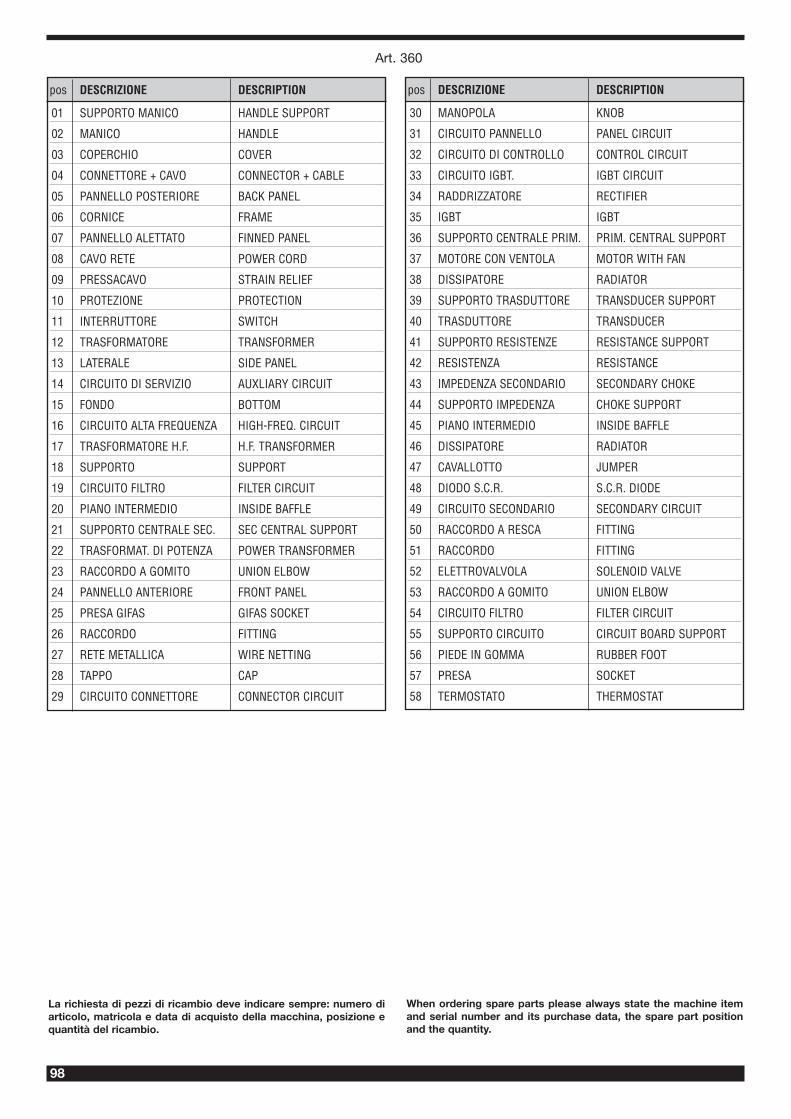
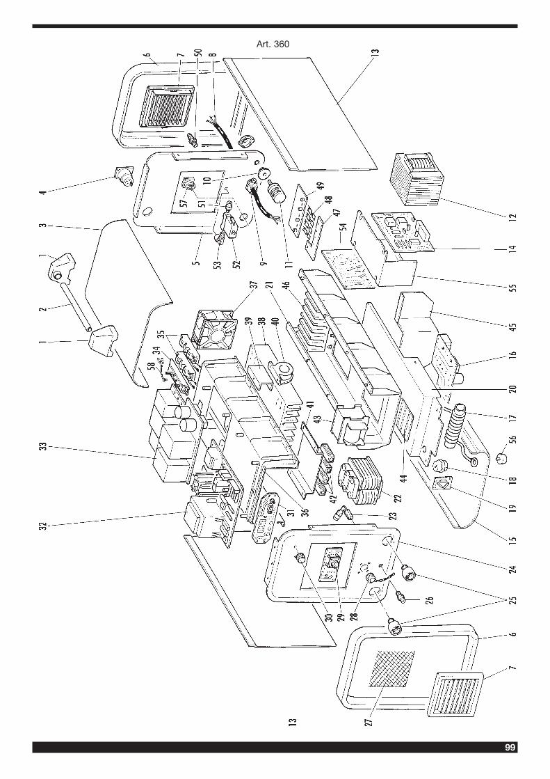
When ordering spare parts please always state the machine itemand serial number and its purchase data, the spare part positionand the quantity.
La richiesta di pezzi di ricambio deve indicare sempre: numero diarticolo, matricola e data di acquisto della macchina, posizione equantità del ricambio.
Art. 360
99
Art. 360
100
Art. 362
101
pos DESCRIZIONE DESCRIPTIONpos DESCRIZIONE DESCRIPTION
001 LATERALE FISSO FIXED SIDE PANEL
002 COPERCHIO COVER
003 CAVO RETE POWER CORD
004 PRESSACAVO STRAIN RELIEF
005 PANNELLO POSTERIORE BACK PANEL
006 PORTA FUSIBILE FUSE HOLDER
007 PROTEZIONE PROTECTION
008 RACCORDO FITTING
009 CORNICE FRAME
010 PANNELLO ALETTATO FINNED PANEL
011 MOTORE CON VENTOLA MOTOR WITH FAN
012 TRASDUTTORE TRANSDUCER
013 CIRCUITO SECONDARIO SECONDARY CIRCUIT
014 DIODO S.C.R. S.C.R. DIODE
015 SUPPORTO MOTORE MOTOR \SUPPORT
016 SUPPORTO CENTRALE DX. RIGHT CENTRAL SUPPORT
017 TRASFORMATORE DI POTENZA POWER TRANSFORMER
018 IMPEDENZA IMPEDANCE
019 TRASFORMATORE H.F. H.F. TRANSFORMER
020 SUPPORTO CENTRALE SX. LEFT CENTRAL SUPPORT
021 FONDO BOTTOM
022 CIRCUITO FILTRO FILTER CIRCUIT
023 SUPPORTO SUPPORT
024 CIRCUITO ALTA FREQUENZA HIGH-FREQ. CIRCUIT
025 PRESA SOCKET
026 PROTEZIONE PROTECTION
028 GOLFARA EYEBOLT
029 TAPPO CAP
030 RACCORDO FITTING
031 RACCORDO FITTING
032 PANNELLO ANTERIORE FRONT PANEL
033 CIRCUITO CONNETTORE CONNECTOR CIRCUIT
034 MANOPOLA KNOB
035 CIRCUITO DI CONTROLLO CONTROL CIRCUIT
036 CIRCUITO DI SERVIZIO AUXILIARY CIRCUIT
037 SUPPORTO CIRCUITO CIRCUIT BOARD SUPPORT
038 CIRCUITO FILTRO FILTER CIRCUIT
039 TRASFORMATORE DI SERVIZIO AUXILIARY TRANSFORMER
040 PIANO INTERMEDIO INSIDE BAFFLE
041 PROTEZIONE PROTECTION
042 CIRCUITO DI CONTROLLO CONTROL CIRCUIT
043 DISSIPATORE RADIATOR
044 RACCORDO FITTING
045 ELETTROVALVOLA SOLENOID VALVE
046 INTERRUTTORE SWITCH
047 CIRCUITO IGBT IGBT CIRCUIT
048 IGBT IGBT
049 TERMOSTATO THERMOSTAT
050 RADDRIZZATORE RECTIFIER
051 DISSIPATORE RADIATOR
052 SUPPORTO CENTRALE PRIM. PRIM. CENTRAL SUPPORT
053 RESISTENZA RESISTANCE
054 SUPPORTO RESISTENZE RESISTANCES SUPPORT
055 SUPPORTO CENTRALE SEC. SEC. CENTRAL SUPPORT
056 CAVALLOTTO JUMPER
058 CAVALLOTTO JUMPER
059 ISOLAMENTO INSULATION
060 GOLFARA EYEBOLT
061 SUPPORTO MANICO HANDLE SUPPORT
062 MANICO HANDLE
Art. 362
102
Art. 362
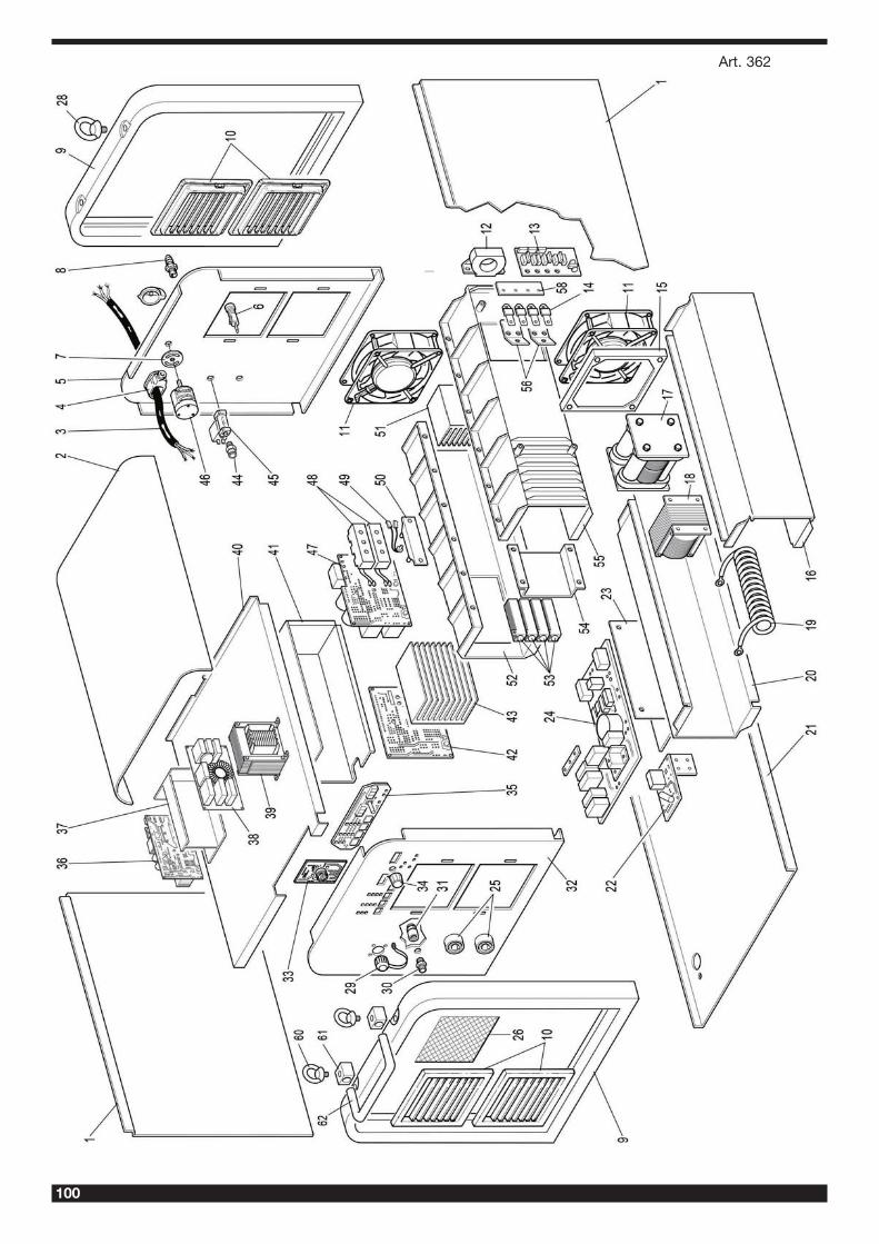
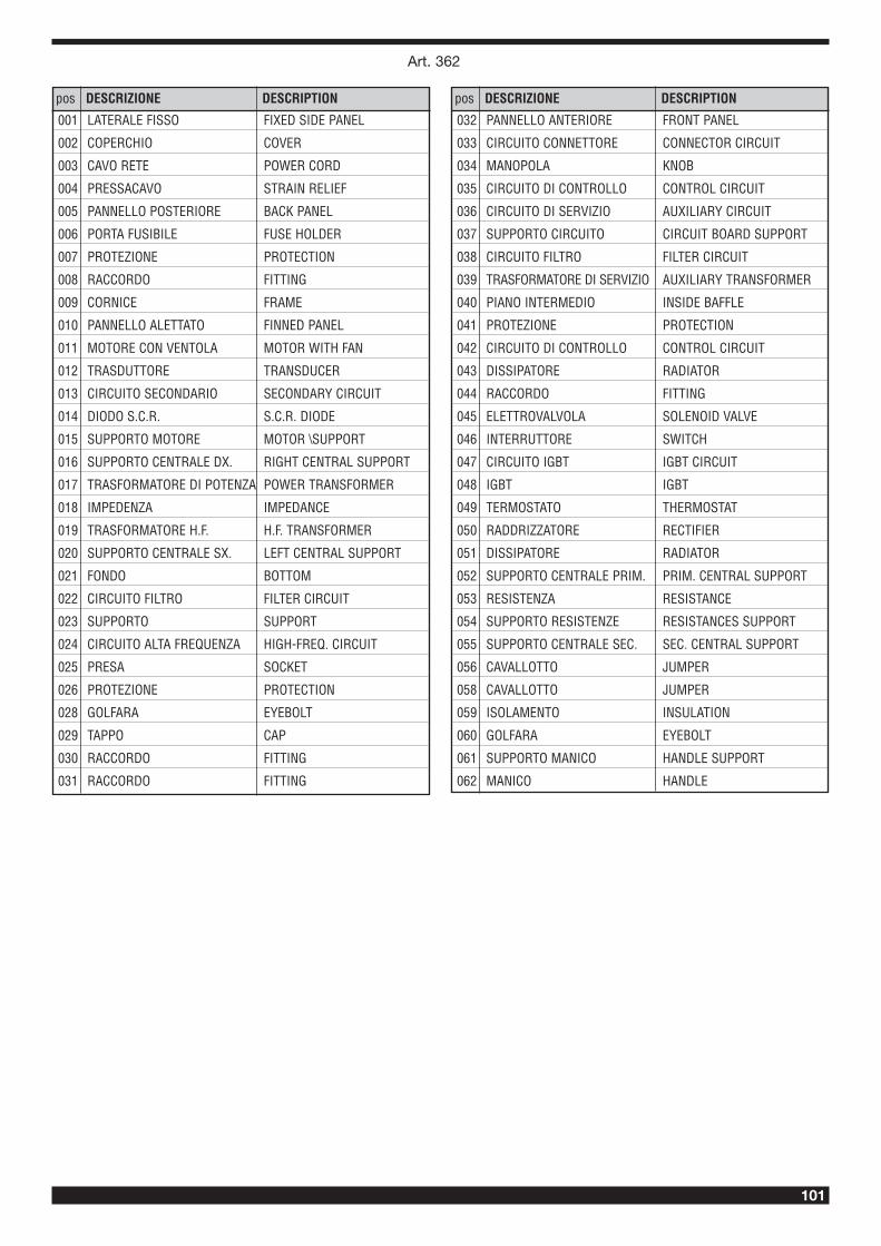
When ordering spare parts please always state the machine item andserial number and its purchase data, the spare part position and thequantity.
La richiesta di pezzi di ricambio deve indicare sempre: numero di arti-colo, matricola e data di acquisto della macchina, posizione e quantitàdel ricambio.

103
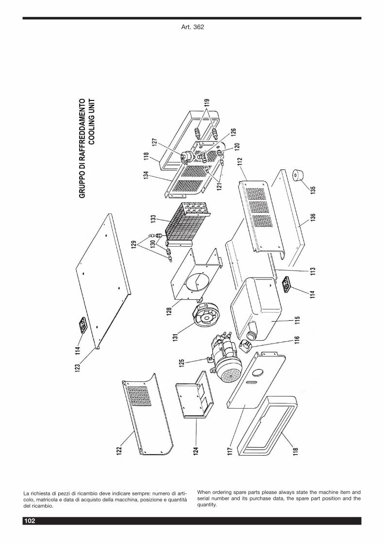
pos DESCRIZIONE DESCRIPTION
112 LATERALE DESTRO RIGHT SIDE PANEL
113 FONDO GRUPPO DI RAFF. COOLING UNIT BOTTOM
114 APPOGGIO REST
115 SERBATOIO TANK
116 TAPPO CAP
117 PANNELLO ANTERIORE FRONT PANEL
118 CORNICE FRAME
119 RACCORDO FITTING
120 RACCORDO FITTING
121 RACCORDO FITTING
122 LATERALE SINISTRO LEFT SIDE PANEL
123 COPERCHIO COVER
124 SUPPORTO SUPPORT
125 ELETTROPOMPA MOTOR PUMP
126 RACCORDO A TRE VIE T-FITTING
127 PRESSOSTATO PRESSURE SWITCH
128 SUPPORTO VENTOLE FANS SUPPORT
129 RACCORDO FITTING
130 RACCORDO BICONO BICONICAL FITTING
131 MOTORE CON VENTOLA MOTOR WITH FAN
133 RADIATORE RADIATOR
134 PANNELLO POSTERIORE BACK PANEL
135 PIEDE FOOT
136 FONDO BOTTOM
Art. 362
104
La richiesta di pezzi di ricambio deve indicare sempre: numero di arti-colo, matricola e data di acquisto della macchina, posizione e quantitàdel ricambio.
When ordering spare parts please always state the machine item andserial number and its purchase data, the spare part position and thequantity.
Art. 362
105
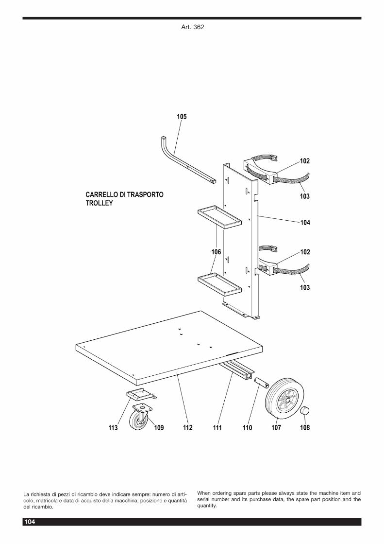
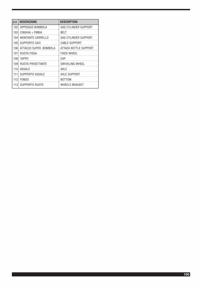
102 APPOGGIO BOMBOLA GAS CYLINDER SUPPORT
103 CINGHIA + FIBBIA BELT
104 MONTANTE CARRELLO GAS CYLINDER SUPPORT
105 SUPPORTO CAVI CABLE SUPPORT
106 ATTACCO SUPER. BOMBOLA ATTACK BOTTLE SUPPORT
107 RUOTA FISSA FIXED WHEEL
108 TAPPO CAP
109 RUOTA PIROETTANTE SWIVELING WHEEL
110 ASSALE AXLE
111 SUPPORTO ASSALE AXLE SUPPORT
112 FONDO BOTTOM
113 SUPPORTO RUOTE WHEELS BRACKET
pos DESCRIZIONE DESCRIPTION

108
CEBORA S.p.A - Via Andrea Costa, 24 - 40057 Cadriano di Granarolo - Bologna - ItalyTel. +39.051.765.000 - Fax. +39.051.765.222
www.cebora.it - e-mail: [email protected]