instruction manual for rescue equipment hydraulic power
TRANSCRIPT

175635085 EN
(Translation of the original instruction manual)
replaces 07.2020Edition 05.2021
Instruction manual for rescue equipment
Hydraulic power units P 635
P 635 SEP 635 SG

2
Content Page1. Dangerclassifications 4
2. Productsafety 5
3. Intendeduse 9
4. Powerunitdesignation 10
5. Functionaldescription 10 5.1 General information 10 5.2 Installation of the power unit 11 5.3 Motor variants 14 5.4 Valves 15 5.5 Pumps 16 5.6 Frame with side sections 16 5.7 Connection to the rescue equipment 16 5.8 Hose reels 17 5.9 Carrying handle 17 5.10 Toolholder 17
6. Connectingthehoses/devices 18
7. Set-upandcommissioning 20 7.1 Set-up 20 7.2 Commissioning 20
8. Operation 22 8.1 Starting the engine 22 8.2 Turningtheengineoff 23 8.3 Refuelling (petrol engines only) 23 8.4 Controlling the valves 24 8.5 Hose reels 25 8.6 Telescopic carrying handles 27 8.7 Toolholder 28
9. Dismantlingtheequipment/deactivationfollowingoperation 31

3
Content Page10.Tests 32 10.1 Recommended test intervals 32 10.2 Hydraulic unit with petrol engine 33 10.3 Hydraulic unit with electric motor 34 10.4 Hose reels 35
11.Maintenanceandrepair 36 11.1 General information 36 11.2 Service work on the hydraulic unit 37 11.3 Additional service work on unit with a petrol engine 39 11.4 Maintenance work on mounted hose reel 42
12.Faultanalysis 48
13.Technicaldata 55 13.1 Power Unit 55 13.2 Noise emissions (Sound pressure level) 66 13.3 Sparking plug 68 13.4 Sparking plug spanner 68 13.5 Fuel 68 13.6 Engine oil 69 13.7 Hydraulicfluidrecommendation 69 13.8 Operating and storage temperature range 69
14.ECDeclarationofConformity 70
15.Notes 71

4
Wearahelmetwithafaceguard
Wearprotectivegloves
Wearsafetyshoes
Properrecycling
Protecttheenvironment
Readandfollowoperatinginstructions
Wedifferentiatebetweenvariousdifferentcategoriesofsafetyinstructions.Thetableshownbelowshowsyouanoverviewoftheassignmentofsymbols(pictograms)andsignalwordstothespecificdangerandthepossibleconsequences.
1. Danger classifications
Pictogram Damage / injury to Key word Definition Consequences
Persons
DANGER! Immediatedanger Deathorsevereinjury
WARNING!Potentiallydangeroussituation
Potentialdeathorseriousinjury
CAUTION! Lessdangeroussituation
Minororslightinjury
Property
ATTENTION!Dangerofdamage
toproperty/environment
Damagetotheequipment,
damagetotheenvironment,damagetosurroundings
- NOTE
Handlingtipsandotherimportant/usefulinformation
andadvice
Noinjury/damagetopersons/environment/
device

5
2. Product safetyLUKAS products are developed andmanufactured to ensure the best performance andqualitywhenusedasintended.Thesafetyoftheoperatoristhemostimportantconsiderationinproductdesign.Furthermore,theoperatinginstructionsareintendedtohelpinusingLUKASproductssafely.Thegenerallyapplicablelegalandotherbindingregulationspertainingtothepreventionofaccidentsandprotectionoftheenvironmentapplyandaretobecompliedwithinadditiontotheoperatinginstructions.Theequipmentmustonlybeoperatedbypersonswithappropriate training in thesafetyaspectsofsuchequipment–otherwise,thereisadangerofinjury.Wewouldliketopointouttoallusersthattheyshouldreadcarefullytheoperatinginstructionsandtheinstructionscontainedthereinbeforetheyusetheequipment,andthattheyshouldcarefullyfollowsuch.Wefurtherrecommendyouhaveaqualifiedtrainershowyouhowtousetheproduct.
CAUTION!The operating instructions for the hoses, accessories and the connecteddevicesmustalsobeheeded!
Evenifyouhavealreadyreceivedinstructiononhowtousetheequipment,youshouldstillreadthroughthefollowingsafetyinstructionsagain.
CAUTION!Ensure that the accessories and connected equipment are suitable for themaximumoperatingpressure!
Pleaseensurethatnobodypartsorclothinggetstuckbetweenthevisiblymovingparts.
Immediatelyreportanychangesthatoccur(includingchangesinoperatingbehaviour)totheappropriatepersons/departments!Ifnecessary,theequipmentistobeshutdownimmediatelyandsecured!
Wearprotectiveclothing,safetyhelmetwithvisor,safetyshoesandprotectivegloves.
Checktheequipmentforvisibleflawsordamagebeforeandafteruse.
Workingundersuspendedloadsisnotpermittedwheresuchloadsarebeingliftedonlybymeansofhydraulicdevices.Ifthisworkisunavoidable,suitablemechanicalsupportsarealsorequired.
Checkalllines,hosesandscrewedconnectionsforleaksandexternallyvisibledamage,andrepairimmediately!Escapinghydraulicfluidcancauseinjuriesandfires.

6
Intheeventofmalfunctions,immediatelydeactivatethedeviceandsecureit.Repairthefaultimmediately.
Donotcarryoutanychanges(additionsorconversions)totheequipmentwithoutobtainingtheapprovalofLUKASbeforehand.
Observeallsafetyanddangerinformationonthedeviceandintheoperatinginstructions.
Allsafetyanddangerinformationonthedevicemustalwaysbecompleteandinalegiblecondition.
Pleaseensurethatallsafetycoversarepresentontheequipmentandthattheyareinproperandadequatecondition.
Anymodeofoperationwhichcompromisesthesafetyand/orstabilityofthedeviceisforbidden!
Safetydevicesmustneverbedisabled!
Themaximumoperatingpressuresetontheequipmentmustnotbechanged!
Makesurebeforeswitchingon/startingupthedeviceandduringitsoperation,thatthiswillputnooneindanger.
Observeallintervalsforrecurringtestsand/orinspectionsthatareprescribedorstatedintheoperatinginstructions.
Whenworkingclosetolivecomponentsandcables,suitablemeasuresmustbetakentoavoidcurrenttransfersorhigh-voltagetransferstotheequipment.
OnlyoriginalLUKASaccessoriesandsparepartsaretobeusedforrepairs.Whenworkingwiththisequipmentorwhentransportingit,ensurethatyoudonotgetcaughtupinthehoseorcableloopsandtrip.
Thebuild-upofstaticchargeandthereforepossiblesparkingmustbeavoidedwhenhandlingthedevice.
Donottouchtheengineandexhaustsystemwhenrunningwithcombustionenginepumpsbecauseofthedangerofburning.
Motorisedpumpsmustnotbeoperatedinareasatriskofexplosion!
Combustionenginesmustnotbeoperatedinenclosedspacesbecauseofthedangerofpoisoningand/orsmothering.

7
Keepcombustionenginesandtheirfuelsawayfromsourcesofignitionsinceotherwisetherewillbeadangerofexplosion.
Alldamagedelectricalcomponentse.g.scorchedcables,etc.aretobereplacedimmediately!
Inordertopreventthedangeroffire,youshouldensureadequateventilationwhenoperatingcombustionenginesandyoumustkeepasafetydistanceofatleast1m(39.4 in.)towallsandotherscreens.
Damagetoelectricalcomponentsmustonlyberepairedbyaqualifiedelectricianincompliancewithallapplicablenationalandinternationalsafetyguidelinesandregulations.
Makesurethatthecombustionenginesarealwaysstandingonasflatandhorizontalasurfaceaspossibletopreventfuelfromleakingout.
Whensettinguptheunits,youmustmakesurethattheyarenotimpairedbytheinfluencesofextremetemperatures.
Theequipmentisfilledwithhydraulicfluid.Thishydraulicfluidcanbedetrimentaltohealthifitisswallowedoritsvapourisinhaled.Directcontactwiththeskinmustbeavoidedforthesamereason.Also,whenhandlinghydraulicfluid,notethatitcannegativelyaffectbiologicalsystems.
Whenworkingwithorstoringtheequipment,ensurethatthefunctionandthesafetyoftheequipmentarenotimpairedbytheeffectsofsevereexternaltemperaturesorthattheequipmentisdamagedinanyway.Pleasenotethattheequipmentcanalsoheatupoveralongperiodofuse.
Makesurethereisadequatelightingwhileworking.
Beforetransportingtheequipment,alwaysensurethattheaccessoriesarepositionedinsuchawaythattheycannotcauseanaccident.
Alwayskeeptheseoperatinginstructionseasilyaccessibleattheplaceofoperation.
Ensuretheproperdisposalofallremovedparts,leftoveroil,hydraulicfluidandpackagingmaterials.
Ifyouspillanyfuelwhenusingcombustionengines,youmustremovethespilledfuelcompletelybeforestartingtheengine.
Refuellingwhilsttheengineisrunningisstrictlyprohibited!

8
The generally applicable, legal and other binding national and international regulationspertainingtothepreventionofaccidentsandprotectionoftheenvironmentapplyandaretobeimplementedinadditiontotheoperatinginstructions.
WARNING/CAUTION!Thedeviceisintended exclusively for the purpose stated in the operating instructions (see chapter "Proper Use"). Any other use is not in accordance with its designated use.Themanufacturer/supplierisnotliableforanydamagesresultingfromimproperuse.Theuserbearssoleresponsibilityforsuchuse.Proper use includes observance of the operating instructions and compliance with theinspectionandmaintenanceconditions.
Never work in a fatigued or intoxicated state!
WARNING/CAUTION!Ifyoustillinjureyourselfonthehydraulicunit,cleanthewoundimmediatelyandconsultadoctortohaveitattendedto!Ifyougethydraulicfluidinyoureye,rinseitimmediatelyseveraltimeswithclear,cleanwaterandconsultadoctor!Also,ifyouswallowhydraulicfluidyoushouldconsultadoctor!
9
3. Intended use
You can obtain accessories and replacement parts for the rescue apparatus from yourauthorisedLUKASdealer!
WARNING/CAUTION!Thesafetyinstructionsinthisoperatinginstructionmanualconcerningthesiteoferectionandtypeoferectionmustalwaysbeobserved!
LUKAS hydraulic units are specially designed to supply LUKAS rescue equipment withhydraulicfluidsothatthisequipmentcanbeusedtorescuevictimsofroad,railorairtrafficaccidentsaswellasfrombuildings.Their use for supplying pressure / fluid to rescue equipment of other manufacturers ispossible,yet requires the technical inspectionandapprovalbyLUKAS ineach individualcase.Theequipmentisnotdesignedtooperatewithouthosesorequipment(operatingtimewithouthosesorequipment<15minutes).
ATTENTION!Whenselectingtheunitstoconnecttotheunit,bearinmindthatthemaximumpossibleuseablevolumeofhydraulicfluidislimited.Thesumofthemax.requiredoperatingvolume(hydraulicfluid)ofallconnectedequipmentmustnotexceedthemaximumpossibleusablevolumeofthepowerunit!
NOTE:AlwaysregisteryourhydraulicunitontheLUKASHydraulikGmbHinternetsite.Thisistheonlywaytoguaranteeyourextendedwarrantycover.Beforeyouusecouplingsfromadifferentcompany,youmustcontactLUKASoranauthoriseddealer.
LUKASP635unitsarenot explosionprotected!Whenusing the equipment in explosion-risk areas youmust make sure thatoperationoftheunitdoesnottriggeranexplosion!TheresponsibilityforexplosionpreventionorforrulingoutworkwiththeP635restswiththeoperatorofthedeviceorwiththepersonresponsibleattheplaceofuse.When working in areas at risk of explosion, all applicable legal, national and international regulations, standards and safety rules for avoiding explosions must be observed without limitation!
The equipment should not come into contact with acids or alkalis. If this isunavoidable,cleantheequipmentimmediatelyafterwardswithasuitablecleaningagent.

10
4. Power unit designation
P 635 S G
Codingforhydraulicpowerunits
Typegroup
Valvevariants
Motorvariants
Valve variants: S = Simultaneousoperation Motor variants: G = Petrolengine E = Electricmotor
Specifications: DHR = Withintegralreels Tube variants: COAX = Tubeintube
InthecaseofallLUKAShydraulicpowerunits,thehydraulicpumpisoperatedwithamotor.Thepumpconveysthefluidfromthehydraulicoiltankandbuildsupthepressureinthetool.Fluidisdistributedtotheconnectedequipmentthroughcontrolvalves.
TwoversionsoftypeP635unitareavailable: 1. smallframewithoutreel 2. largeframewithmountedreel
The telescopic carrying handles are an optional accessory for the first version and canalwaysberetrofitted.
5. Functional description 5.1 General information
DHRSpecification
COAXTubevariants
NOTE:Ahosereelisonlyincludedwiththesecondversionandcannotberetrofittedatalaterdate!

11
5.2 Installation of the power unit
1 Petroltank 2 Hydraulicfluidtank 3 Enginewithhydraulicpump 4 Connectingblockwith
controlvalves 5 Speedadjustinglever 6 Cable-pullstarter 7 "TURBO"controllever 8 Mono-coupling(female) 9 Fueltankcap10 Fillercaphydraulicfluid11 Frame12 Rubberbuffer13 Sidepanel14 Airfilter15 Choke16 Fueltap17 ON/OFFswitch(engine
switch)18 Engineoilfillercap/dipstick19 Filllevelindicator
Equipmentback
15 16 17
6
14
18
5
P 635 SG
19
14
3
7
8
2
9
10
11
12 13
19

12
8 Mono-couplings10 Hydraulicfluidfillcap20 Telescopiccarryinghandle (alsooptionallyavailableforretrofitting)21 Hosereel22 Lock(hosereel)23 Crankhandle(hosereel)24 Hoseguide25 Toolholder
8
20
21 242223
10
25
P 635 SG-DHR-COAX
P 635 SG-DHR

13
1 Electricmotorwithhydraulicpump
2 Hydraulicfluidtank 3 Connectingblockwith
controlvalves 4 Mono-coupling(female) 5 Fillercaphydraulicfluid 6 Filllevelindicator 7 Frame 8 Rubberbuffer 9 Sidepanel10 ON/OFFswitch(engine
switch)11 “TURBO”controllever20 Telescopiccarryinghandle (alsooptionallyavailable
forretrofitting)21 Hosereel22 Lock(hosereel)23 Crankhandle(hosereel)24 Hoseguide25 Toolholder
P 635 SE-DHR-COAX
P 635 SE
1
4
8
7
6
9
3
2
5
11
10
4
20
21 2422
523
25

14
5.3 Motor variants
WARNING/CAUTION! See also the separate operating instructions of each engine manufacturer
accompanyingthedelivery.
5.3.1 Petrol engineThesehydraulicunitsareequippedwithacombustionenginedrivenbythefuel"petrol".Thepowerunitsareequippedwithacable-pullstarterwithwhichtheengineisstarted.(For specific details, please consult the separate operating instructions of the enginemanufacturer!)
NOTE:TheengineinstalledintheLUKASpowerunitsdoesnotmatcheverydetailoftheenginedescribedinthemanufacturer'sseparateoperatinginstructions.Nevertheless, it is important that you follow all safety rules and operating,maintenance and storage instructions in the separate engine instructions asabsolutesincetheyarenotaffectedbyadjustmentsmadebyLUKAS.
HONDA motors have a main switch that must be activated to switch the power unit on and off.Thespeedadjustingleveronthesepowerunitshastwoswitchpositions.Switch position 1 (standard): Speed 3000 1/min " " and Switch position 2: Speed 3800 1/min " ".
Thesettingisadjustedbymovingthespeedadjustinglever.
5.3.2 Electric motorThesehydraulicunitsareequippedwithanelectricmotor.Theelectricmotorisdrivenbyelectricityfromthemainssupplyorbyelectricityproducedbygenerators.Inthecaseofoperationwithgenerators,makesurethatvoltagefluctuationsdonotoccur,asthesehaveadirectinfluenceonthepumpingcapacityandstabilityofthehydraulicunit.Thepossibleoperatingvoltage,thecurrentfrequencyandtherequiredintensityofcurrentcanbefoundintheseparateinstructionsforyourunitinthechapterentitled“Technicaldata”.
NOTE:Using an extremely long electrical connection cable may reduce the outputresistanceandthepowersupplytothemotor.Theperformanceofthemotorwillbeaffectedasaresult.

15
5.4 ValvesBothvalvesofthepowerunitinthepumpblockarefixedinplace.Thepumpblockisfullyintegrated into the hydraulic power unit. The hose assemblies (pressure line (grey) andreturn(blue))mustbeconnectedtothepumpblock.Therescueequipmentisconnectedtothehoseassemblies.ModelP635unitsareequippedwithaSIMOconnectingblock.
TheconnectingblockoftheP635alsohasaTURBOfunction.Witha“TURBO”controllever,eitherbothconnecteddevicescanbesuppliedsimultaneouslywithhydraulicfluid,orasingledevicecanbesuppliedwithdoublethevolume(=TURBOfunction). By supplying at double the feed rate, the speed of the connected device isincreased.
Thehosesareconnectedwiththeconnectingblockviamono-couplings.
5.4.1 Control valve "simultaneous operation" (SIMO)Thisvalveenablestheconnectionoftwopressurehosesandtworeturnhoses.Ithastwoswitching options, each of which controls the pressure application of the pressure hosethatismarkedaccordingly.Thismeansthattwo devices can be supplied with pressure simultaneously and independently of each other.Without impairingtheworkoutput, itenablesworkwithtwodevicessimultaneouslyandindependentlyofeachother.
ATTENTION!When operating several pieces of rescue equipment with one unit, ensurethat theusablevolumeofhydraulicfluid in thepowerunit isgreater than themaximumpossibleoperatingfluidvolumeofallconnectedrescueequipment.

16
TheLUKAShydraulicpowerunitsmodelP635areequippedwithaSIMOconnectingblock.Thepumpisrigidlyconnectedtotheconnectingblock. Double-flowpumpforoperatingwithSIMOvalve
Thepumpusedalwayshastwopressurestagesperpumpfeedflow,onelowpressureandonehighpressure.
Low-pressurelevel(LP) = upto14MPa*
High-pressurelevel(HP)= upto70MPa*
Thechangeoverfromlowpressuretohighpressureiscarriedoutautomaticallybythepump.Thissystemissecuredwithapressurelimitingvalve.Therefore,themaximumpermissiblesystempressurecannotbeexceeded.
5.5 Pumps
*)1MPa=10bar)
5.6 Frame with side sectionsTheP635hydraulicpowerunitismountedwithinaframe.Theframeandsidepanelsarealsoused,despitetherobustdesign,toprotectthepowerunitfromexternalinfluences,suchasforexample,dirtordamage.
5.7 Connection to the rescue equipment
Connectiontotherescueequipmentisviaextensionhosepairsorviahosereels.Theyaresuppliedinvariouslengths.(Forspecificdetails,pleaseconsulttheLUKASrangeofaccessoriesorcontactyourLUKASdealer.)
WARNING/CAUTION!Forsafetyreasons,thepressuresetonthisvalvemustnotbeadjusted(withouttheapprovalofLUKASdirectly)!

17
5.8 Hose reelsThehosereelsweredesignedtostorehosepairsleadingbetweenthehydraulicsupplyandtheworkingequipment(hosepairsareincludedinthedeliveryasstandard).Thehosepairsareconnectedtothehosereelsandrolledontothedrums.Ahose reelwith hosepairs can cover longdistancesbetween thehydraulic supply andtheworkingequipment,allowingyoutokeepthehydraulicunitonavehicle,forexample.The possibility of rolling up and unrolling the hose allows you to adapt the hose lengthaccordinglyandreducetheamountofunnecessaryorpotentiallydangerousexcesshoselyingontheground.Thehosepairsareeasiertotransportandstorewhenfullyrolledup.Moreover,thehosereelsareequippedwithahoseguidethatfacilitateseasierrollingupandunrolling.Theunitisconnectedtotheworkingequipmentviacouplings.
CAUTION!Inordertoavoidpotentiallossesinpressure,thelengthofthehoselinesmustnotexceed30m!
5.9 Carrying handleLUKAShydraulicunitsoftypeP635withahosereelareequippedwithcarryinghandles.TheP653canbetransportedmoreergonomicallyusingthecarryinghandles.
5.10 ToolholderTypeP635LUKAShydraulicunitswithahosereelarefittedwithaToolholder.ItispossibletoadaptthemounttoaccommodateallLUKAScuttersandspreadersaswellasmodifyitatalaterdate.TheToolholderallowsyoutotransportaunitwithdevicesstillattached.Younolongerhavetodetachandstoredevicesseparatelyafteruse.YouonlyhavetowindthehoselinesontothereelsandpositionthedevicesontheToolholderagain.Devicessecuredtotheunitdonotposeariskduringtransport.

18
ATTENTION!Whenconnectingthehoseassemblies/units,alwaysensurethattheconnectioncomponentsarenotdirty.Cleanpriortouseifnecessary!
WARNING/CAUTION! Before connecting the equipment, make sure that all the components used are suitable for the maximum operating pressure of the hydraulic unit! In cases of doubt, you must consult LUKAS directlybeforeconnectingtheequipment!
6. Connecting the hoses / devices
Mono-couplinghalve(male)
Mono-couplinghalve(female)
Dustprotectioncaps
Thehoselines/unitsareconnectedviaquick-disconnectcouplinghalves(femaleandmale)tothehydraulicpumporhosereelinsuchawaythattheycannotbeswappedover.
0
1
0

19
BA C
C
Remove the dust caps before coupling together. Then push themale and female partstogetherand turn the locking sleeveon the female coupling in thedirection "1" until thelockingsleeveclicks inplace.Theconnectionhasbeenmadeand locked.Decoupling isaccomplishedbyturningthelockingsleeveindirection"0".Couplingofthehoseassemblieswhenunderpressureisalsopossible,assumingthattheconnectedequipmentisnotturnedon.
NOTE:We recommend connecting the coupling halves in a depressurised statewhenworkinginareaswithlowambienttemperatureandusingextensionhoseassemblies/hosereels,asotherwisethecouplingmayrequiretheapplicationofagreatdealofforce.
Fordustprotection,thesupplieddustcapsmustberefitted.
Using the dust protection caps: Thedustprotectioncaps"A"havetwoexternalgrooves"B".Thedustprotectioncapsmustbeinsertedinthefemalecouplinginsuchawaythatthegroovescanbeguidedoverthepins"C".Screwinthedustprotectioncapstothestoptofixinthefemalecouplings.

20
7. Set-up and commissioning
7.1 Set-up
7.2 Commissioning
WARNING/CAUTION!Because of possible spark formation, combustion engine units and electricalequipment cannot be used in an explosion-risk area. Units with combustionenginesmustnotbeusedinenclosedspaces,asthereisadangerofpoisoningand/orasphyxiation!
Theunitistobesetupinasuitablelocation(securelocation/flatsurface/sufficientdistancefromvehicles,loads,sourcesofignition,etc.).LUKASunitsworkperfectlyatanangleofupto20°.However,inordertoguaranteemaximumsafetyandfluidwithdrawal,theyshouldbeoperatedinashorizontalapositionaspossible.
ATTENTION!Nevermixupthefuelandhydraulicfluidtankswhenfillingthetank;thiscandamagethepowerunit!
NOTE:Theengineoil levelmustbeinspectedbeforethefirstcommissioningorafterlongerperiodsofstorage.Firstfilltheengineortopuptheengineoil!Forsafetyreasons,LUKASpowerunitsdonotcontainengineoilupondelivery!
7.2.1 First commissioning - Powerunitwithoutengineoil,hydraulicfluidandpetrol.
1.Pour hydraulic oil into thehydraulic fluid tank until thefill level indicator is betweenMIN/MAX (see illustration ontheright).
Hydraulicoilfilllevelindicator

21
2.Nowbleedthehydraulicpowerunit:3.Opentheventingplugonthepumpblock
4.Tiltthepowerunitbackwardsbyapprox.90°(seeillustration)andwaituntiloilcomesoutfromthebolt.
5.Whenoilcomesoutattheventingplug,theairhasbeenremovedfromthepump.Firstclosetheventingplugandthenreturnthepowerunittothelevel.
6.Pourintheengineoilaccordingtotheinstructionsinthescopeofdeliveryincludedwiththeseparatemanufactureroperatinginstructionsregardingthefilleropening(engineoilfillercap,seechapter"Installationofthepowerunit").
7.Pourfuel(petrol)intothetankuntilthefilllevelisjustbelowthefilleropening.Ifthepowerunitisrestingonaninclinedsurface,donotfillthetanktoitsmaximumcapacity.
8.Checkthehydraulicoillevel.Topupifnecessary.9.Nowconnect theextensionhosesand/orhose reels (unlessalreadyconnected to the
unit)and/orcoupletherescueequipment.
VentingplugPumpblock
90°90°90°

22
7.2.2 Commissioning(afterthefirstfillingorpriortouse)
1.Check the fluid level of the engine oil, the hydraulic fluid and the fuel tank.Top up ifnecessary. For precise reading off of the fluid levels and for filling, the hydraulic unitshouldbeaslevelaspossible.
2.Nowconnecttheextensionhosesand/orhosereels(unlessalreadyconnectedtotheunit)and/orcoupletherescueequipment.
8.1.1 Petrol engineBeforestartingthecombustionengine,checkthatthefueltankisfullandthattheengineoilleveliswithinthepermittedtolerances.Ifnecessary,topuptherelevantfluid.
1.Openthepetroltap2.SettheON/OFFswitchtotheONposition.3.MovetheleverfromswitchingpositionAtoswitching
positionB(choke)whenstartingcold4.Pullthecable-starter.5.When themotor is running,switch the leverback to
positionA.
For the detailed procedure for starting the combustionengine,pleaseseetheseparate operating instructions of the engine manufacturer!
8.1.2 Electric motorBeforestartingtheelectricmotors,checkthatallelectricalconnectionsandcablesare inproper order. First of all, connect the power cable (formotorswith power supply) to thesupplysocket.TheON/OFFswitchislocatedontheterminalboxofthemotor(seefigurebelow).Tostart,pressthegreenbuttonoftheON/OFFswitch.
BA
8.1 Starting the engine
8. Operation
ATTENTION!Electricmotorsdrawabrief,veryhighstartingcurrent.Whenusingagenerator,youshouldthereforechecktoseethatitcansupplytherelevantcurrentstrength.Thepowersupplymustbeprotectedbya25Afuseatleast.

23
Theenginemustbeswitchedoffforrefuelling!Procedure:1.Openthefueltankcap.2. Fillthetankwithfueluntilthefilllevelisjustbelowthefilleropening.
3.Closethefueltankagainwiththefueltankcap.
WARNING/CAUTION!Besurenottospill fuel. Inparticular,hotenginepartsmustnotcomeintocontactwithfuel;dangeroffireotherwise!Iffuelisspilled,itmustbecleanedupimmediatelywithasuitableabsorbentcloth.Indoingso,becarefulnottoburnyourselfononeofthehotengineparts!Theusedclothmustthenbecleanedordisposedofaccordingtotherelevantprovisionsandguidelines!
8.3 Refuelling (petrol engines only)
8.2.1 Petrol engine1.SettheON/OFFswitchtotheOFFposition.2.Whentheenginehascometoastandstill,closethe
fueltap.
For more details on switching off the engine, please refer to the separate operatinginstructions of the engine manufacturer!
8.2.2 Electric motorToswitchoffthemotorpresstheredbuttonoftheON/OFFswitchonthemotorterminalbox.Whentheengineisswitchedoff,theconnectedhydraulicpumpstopsdelivering.
CAUTION!Nevertouchhotengineparts:thiscouldresultinsevereburns!
8.2 Turning the engine off
ATTENTION!Waitatleast3secondsbeforerestartingthemotortoavoiddamagingtheunit.

24
8.4 Controlling the valves
8.4.1 "Simultaneous operation" control valve (SIMO) P 635 SG/SE
Thepumpblockalsohasa“TURBO”controllever,allowingtheusertoswitchtothe“TURBO”function(seediagramabove).Withthisfunction,theswitchpositionofthe“TURBO”controllevercanbeusedtosupplyoneofthetwoconnectionswithdoublethevolume.The "TURBO" function is activated by turning the “TURBO” control lever towards theconnectionthatistobepressurisedatthedoubledpumpingoutput.
NOTE:The“TURBO”controllevermustalwaysbemovedcompletelyuptothestop.

25
8.5 Hose reels 8.5.1 Locking brakeThelockingbrakeisdesignedtopreventhosepairsfromunrollingduringtransportation!Pullandturnknobthrough90°toreleasethelockingbrake.Toapplythelockingbrake,turnknobthroughapprox.90°untilitengagesautomatically.
8.5.3 UnrollingPullthehosepairuntiltherequiredlengthhasunrolledfromthehosereel.
CAUTION!Releasethelockingbrakeonthehosereelbeforehandtoavoiddamagingthereelandthepairofhoses!
Thecrankhandleshouldmakethehoseeasiertorollup!Tousethecrankhandle,pulllever,foldoutwardsthrough90°andreleasesothatitengages.To foldaway thecrankhandle,pull lever fold inwards through90°and releaseso that itengages.
8.5.2 Crank handle
90° 90°

26
8.5.4 Rolling up
NOTE:Werecommendusingthecrankhandletorollupthehoses!
- Foldoutthecrankhandle.- Checkthatthelockingbrakeonthedoublehosereelsisreleased.- Alignthereelssothattheunrolledhosesarerolledupinastraightline.Youwillfindthat
thehosesrollupmoreeasily.- Youcannowrollupthepairofhoselinesbyturningthecrankhandle.
Make sure that the direction of rotation is always the same as shown in the illustration!
Directionofrotation"Rollingup"
Hose
Elbowpiece
Make sure that the pair of hose lines is always rolled up correctly onto the hose drum. We recommend guiding the pair of hose lines with your hand during the rolling process.
You must always guide the pair of hose lines in a perpendicular direction to the reel axis because of the hose guide attached to the hose reel.
- Youmustthenapplythelockingbrakeonthedoublehosereels.
CAUTION!Thebendprotection on the hoses should only rest lightly on the hoseguidewhenthehoseisrolledupcompletely.However,ifthehoselineisrolledupsofarthatthebendprotectionispressedupagainstthehoseguide,thefollowingcouldoccur: - Thehosematerial is stretchedand thehosedamaged,possiblybeyond
repair. - The couplings, bend protection and hoses may be damaged during
transportationorstorage.

27
Alwaysfullyextendandsecurethecarryinghandlesbeforeusingthemtotransporttheunit.When not in use, always insert and secure the carrying handles to prevent them fromrestrictingyourmovementwhenoperatingtheunit.Thehandlesshouldalsobeinsertedandsecuredwhenstoredtoreducetheriskofaccident.
Procedure (fitting the telescopic carrying handles to units without a reel):1. Removeprotectivecovers"A"usingascrewdriver.
2. Insert telescopiccarryinghandle"B" intheframeandscrewinguidesleeve"C"withmedium-strengththreadlocker.
3. Thenslidethetelescopiccarryinghandleallthewayinandlockinposition.
A
BC
8.6 Telescopic carrying handles
Unitswithahose reel are fittedwith carryinghandles.Unitswithoutahose reel canberetrofittedwithhandlesifrequired.ThehandlesshouldbeusedtotransporttheP635.Thetelescopiccarryinghandlesarescreweddirectlytotheframe.Theblankingplugsmustberemovedbeforethehandlescanbeattached.Turnthehandlesclockwise(approx.1revolution)intheendpositions(retractedorextendedcompletely)tosecurethemproperly.Turnthehandlesanticlockwise(approx.1revolution)tounlockthem.

28
8.7 ToolholderTo removea device from thedevice tray, theholdingstrapmustbeopened.Thedeviceistheneasytoremove.
Placementofthespreaderisdonein reverse order.Make sure thattherescuedevicerestsfirmlyonthedevicetray, theholdingstrapislockedandfirmlytightened.
Remove a spreader:
1
3
2
Release the holding strap bypressing the red pushbutton.
Lift up the spreader at the rearhandle.
Remove the spreader in thedirectionofthereel.

29
Procedure (fitting and adjusting the Toolholder):
NOTE:IfyouwishtoinstallaToolholderatalatertimeoradaptanexistingmounttoanewdevice,followtheworkingstepsdescribedbelow.
1.Fastenholder“A”totherail“C”withtwoscrews“B”.
A
B
C
B
2.Fixthesupports“D”and“E”totherail“F”withtwoscrews“B”
D
E
F
B
B
GG
D
F Fastenbracket“D”torail“F”withtwothreadedpins“G”.

30
Dependingonthesizeoftherescuedevices,thesupportsmustbeadapted.Support“E”canbeinstalledonbothsidesoftherail“F”.
3.Nowadaptthesupportstotheappropriaterescuedevices. Loosen the fastening screws slightly so that the supports are easy to move.
Thescrewsmustnotbecompletelyunscrewed. Thesupportscanbeadjustedtoalmostanydeviceoralmostanyindividualpreferred
position. Finallytightenalltheloosenedscrewstofixtheadjustedholderposition.
4.Themountisdismantledinreverseorder.
E
F

31
9. Dismantling the equipment / deactivation following operation
WARNING for power units with combustion engines!Checkthattheengineswitchissettothe“OFF“positionandremainstheretopreventtheunwantedstartingofthepowerunit!
Mono-couplings:If the connected hose assemblies are to be dismantled during shut-down, decouple asdescribedinchapter"Couplingthemono-couplings".Ensurethatyouputthedustprotectioncapsbackontothemono-couplinghalves.
Cleanthehydraulicpowerunitofanystubborndirtpriortostorage.
If theequipment is tobestored fora longerperiodof time, theexterior is tobecleanedcompletely and themechanicallymobile parts are to be lubricated. If storing a unitwithcombustionengine,youshouldalsoremovethefuelfromthefueltank.Avoidstoringthehydraulicpowerunitsinadampenvironment.Observe the additional regulations in the separate operating instructions for the hoses.
CAUTION!Depending on the size and weight of the hydraulic power unit it should betransportedtothestoragelocationbyoneormorepersons.
NOTE:Ifyourunitisequippedwithahosereel,thehosesmustberolledontothereelscorrectly!
Oncetheworkhasbeencompleted,allconnectedequipment is tobereset to itsneutralposition(storageposition)beforetheunitisshutdown.Youcanthenswitchofftheengineofthepowerunitanddisconnectitfromthemainssupply,ifusinganelectricmotor.
32
10. TestsThe hydraulic power units are subject to very high levels ofmechanical stress.A visualinspectionmustthereforebecarriedoutaftereveryuseandatleastonevisualinspectionmustbecarriedouteverysixmonths.This reveals wear and tear in good time; punctual replacement of these wearing partspreventsdamageto theequipment.Alsocheckregularly thatall thesecuringscrewsaretightened(ifapplicable,complywithprescribedtighteningtorques)Every3yearsorwhentheremightbedoubtsregardingthesafetyorreliabilityoftheunit,anadditionalfunctioncheckistobecarriedout(inthisconnection,complywiththeapplicablenational and international regulationswith regard to themaintenance intervals of rescueequipment).Operating time per day In the Federal Republic ofGermany, regular safetyinspections according to the regulations of the Gesetzlichen Unfallversicherung (GUV;connoted‘Legalaccidentinsurance’)aremandatory.
ATTENTION!Cleanoffanydirtbeforecheckingtheequipment!
WARNING/CAUTION!To perform inspections,maintenance and repairs, personal safety equipmentappropriatefortheworkisanabsoluterequirement.(whennecessaryalsousescreens).
LUKASoffersasuitabletestkitforthefunctiontestofthehydraulicunits.(Forspecificdetails,pleaseconsulttheLUKASrangeofaccessoriesorcontactyourLUKASdealer.)
10.1 Recommended test intervals10.1.1 General visual inspection
Avisualinspectionmustbecarriedoutaftereveryuse,butatleastonceeverysixmonths.

33
Visual Inspection
• Tightnessofallhydraulicconnections,• Generaltightness,noleakage(sweatedoilsdonothaveanyinfluenceonthefunction),• isthereanydetectabledamagetotheengine,connectingblocks,ontheframeortheside
sections,• Isthereanysignofdamagetothehydraulicsorfueltank,• Sideplatespresentandtightened,• Presenceand legibility of the identificationplate, all actuation signs, instruction signs,
markingsandwarnings,• Thepresenceandperfectconditionofallcovers(e.g.exhaustdeflector),• Allfluidlevelsarewithinthespecifiedtolerances,• Aretherotaryswitchesandswitchingleversinproperworkingorderandundamaged,• Couplingsmustbeeasytocouple,• Dustprotectioncapsmustbeavailable,• Allrequiredaccessoryparts(e.g.sparkingplug,sparkingplugspannerandfuelcan)are
present.
Functional test• Unconventionalornoticeablenoisesheardduringoperation• Cable-pullstarterfullyfunctional,• Engineswitchfullyfunctional,• Testformaximumload.
10.2 Hydraulic unit with petrol engine
Operating time per day Functional test
upto1hour 1xannually
upto8hours 1xperquarter
upto24hours 1xpermonth
In addition to these test intervals you need to carry out a function test if: - theunitmakessuspiciousnoises, - thereisajustifiedsuspicionofinternaldamagetotheunit.
Ifthenoisesandsuspicionsreferredtoaboveariseseveraltimesinamonth,orifmaximumpressurecannotbeachievedduringthefunctiontest,youneedtocontactLUKAScustomerservice immediately. The contact details are given in the Chapter "Fault analysis".
10.1.2 Function check
NOTE:usetheLUKAStestkit,includingtestinginstructions,forthefunctiontest.
34
Visual Inspection
• Tightnessofallhydraulicconnections,• Generaltightness,noleakage(sweatedoilsdonothaveanyinfluenceonthefunction),• isthereanydetectabledamagetotheengine,connectingblocks,ontheframeortheside
sections,• Isthereanysignofdamagetothehydraulicsorfueltank,• Sideplatespresentandtightened,• Presenceand legibility of the identificationplate, all actuation signs, instruction signs,
markingsandwarnings,• Thepresenceandperfectconditionofallcovers(e.g.fancover),• Allfluidlevelsarewithinthespecifiedtolerances,• ON/OFFswitchinproperworkingorder,undamaged,• Couplingsmustbeeasytocouple,• Dustprotectioncapsmustbeavailable,• Allelectricalattachments(suchascablesandplugs)mustbepresentandundamaged.
Functional test• Unconventionalornoticeablenoisesheardduringoperation• Cable-pullstarterfullyfunctional,• Engineswitchfullyfunctional,• Testformaximumload.
10.3 Hydraulic unit with electric motor
NOTE:usetheLUKAStestkit,includingtestinginstructions,forthefunctiontest.

35
10.4 Hose reelsVisual inspection
Hose reel• Generaltightness(noleaks)• Hosedrumsrotateeasily• Allfixingscrewsarepresentandtightened• Frameanddrumundamaged• Crankhandlepresent,undamagedandfullyfunctional• Lockingbrakeondoublehosereelpresentandfullyfunctional• Allsignspresentandlegible
Hoses• Visualinspectionforvisibledamageandleaks• Checkageofhose(replaceafter10yearsatthelatest)• Hoseconnectiononmountedreelsecureandnotleaking• Couplingsmustbeeasytocouple• Dustcapsfitted
Functional check• Hosepairsunrollandrollupsmoothly.• Nosuspiciousnoises

36
11.1 General informationLUKAShydraulicunitsmodelP635requireonlylimitedmaintenance.Forservice work, specialtrainingisunnecessary;however,knowledgeofthefunctionofthepowerunit,thelegalsafetyinstructionsanddealingwiththerequiredtoolsarebasicprerequisites.
ATTENTION!Neveruseunnecessaryforceduringmaintenanceworkthatcoulddamagethecomponentsofthepowerunitorcompromiseoperationalsafety.
Duetothecomplexinstallation,service workonthehydraulicpowerunitmustonlybeexecutedbytheequipmentmanufacturer,personneltrainedbytheequipmentmanufacturer,orauthorisedLUKASdealers.
WARNING/CAUTION!Protective clothes must be worn when maintenance and repairs are beingcarriedout,sincethedevicesmayalsobepressurisedwhennotinoperation.
Duringwork,ensurethatallcomponentsareparticularlyclean,sincedirtcandamagetherescueequipment!
11. Maintenance and repair

37
ATTENTION!Since LUKAS hydraulic units are designed for top performance, only thosecomponentsinthereplacementpartslistsfortherelevantunitcanbereplaced.Anyothercomponentsintheunitmayonlybereplacedif:- YouhaveparticipatedinanappropriateLUKASservicetrainingcourse.- YouhavetheexpresspermissionofLUKAScustomerservice(uponrequest,
wewillcheckforthegrantofpermission.Examinationineachindividualcasenecessary!)
Whencleaningunitsandequipment,notethatnocleaningagentmaybeusedthathasapHvalueoutsidetherange5-8!
ATTENTION!Attentionmustbepaidtoensuringthatnooperatingfluidscanescapefromunitswithcombustionenginesduringrepairwork!
11.2 Service work on the hydraulic unit
11.2.1 Care instructionsTheexteriorofthedevicemustbecleanedfromtimetotime(not the electrical contacts) andthemetallicsurfaces(not the electrical contacts)mustbetreatedwithasuitableagenttoprotectagainstcorrosion.(Incaseofdoubt,contactyourauthorisedLUKASdealerorLUKASdirectly!)
11.2.2 Function and load test Ifthereisanydoubtregardingthesafetyorreliabilityoftheequipment,afunctionandstresstestmustalsobeperformed.LUKASoffersappropriatetestingequipmentforthis.
11.2.3 Replacing the hydraulic fluid- Afterapprox.200deployments,butafterthreeyearsatthelatest,replacethehydraulic
fluid.- Thefluidshouldbereplacedafterithaswarmedup.- Theenginemustbeswitchedoff!- Theusedhydraulicfluidmustbedisposedofproperly.

38
5. Pourthenewhydraulicfluidthroughthefillerneckintothehydraulictankandclosetheneckagainwithfillercap"B".
6. TheunitthenhastobebledagainasdescribedintheChapter"Commissioning".
Replacing the hydraulic fluid - procedure:1. Placethepowerunitonaslightlyelevatedbasesothatthedrainplugforthehydraulic
fluidcanbeeasilyreached.2. Placeasuitablecollectioncontainerunderthe"A"drainplug.3. Openthe"B"fillercap,removethe"A"drainplugandletthehydraulicfluidrunintothe
providedcollectioncontainer.4. Screwthe"A"drainpluginagain(tighteningtorquemax.5Nm).
11.2.4 Changing decalsAlldamagedand/orillegibledecals(safetynotices,typeplateetc.)mustbereplaced.
Procedure:1.Removedamagedand/orillegibledecals.2.Cleansurfaceswithindustrialalcohol.3. Affixnewdecals.
Takecaretoaffixthedecalsinthecorrectpositions.Ifthisisnolongerknown,youshouldaskyourauthorisedLUKASdealerorcontactLUKASdirectly.
A
B

39
NOTE:Non-observanceofthemaintenanceplancanleadtomalfunctionsthatarenotcoveredbythewarranty.
Fordismantlingthesparkingplug,useacommercially-availablesparkingplugspannerwithuniversaljointandspannersizeof16mm(5/8inch).Astraight/rigidsparkingplugspannerwoulddamageorbreakoffthesparkingplug!
(also observe the separate instructions from the engine manufacturer)
First month or after the first 20 hours (first time):• Replaceengineoil(seeoperatinginstructionsoftheenginemanufacturer).
You must conduct the following service measures every 50 operating hours:• Cleantheairfilterelement.• Afterusinginadustyenvironment,inspecttheairfilterelementandcleanimmediately,
ifnecessary.
You must conduct the following service measures every 100 operating hours:• Replaceengineoil.• Checkthesparkingplug,cleanifnecessary/settheelectrodegapofthesparkingplug
You must conduct the following service measures every 200 operating hours:• Replacethesparkingplug• Replaceairfilter
(Thefollowingserviceworkshouldbeexecutedbyanauthoriseddealer,LUKASdirectlyorthe engine manufacturer.)
You must conduct the following service measures every 300 operating hours:• Replacethesparkingplugandthefilterelement• Cleanandadjustthecarburettor,valveclearance,valveseatandcylinderhead.
You must conduct the following service measures every 1000 operating hours or every 2 years:
• Checkthestarter• Inspecttheenginefordamage• Checkthefuellineandreplace,ifnecessary.
11.3 Additional service work on unit with a petrol engine
40
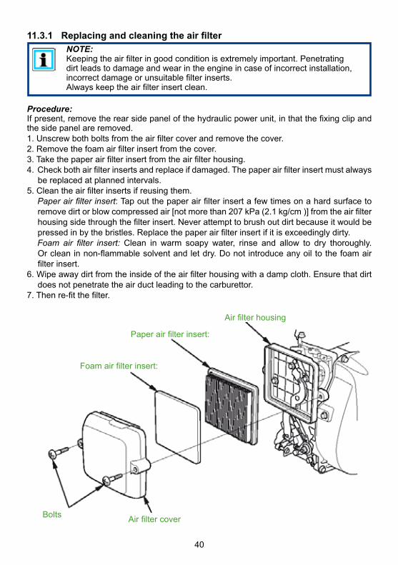
11.3.1 Replacing and cleaning the air filter
Procedure:Ifpresent,removetherearsidepanelofthehydraulicpowerunit,inthatthefixingclipandthesidepanelareremoved.1.Unscrewbothboltsfromtheairfiltercoverandremovethecover.2.Removethefoamairfilterinsertfromthecover.3.Takethepaperairfilterinsertfromtheairfilterhousing.4.Checkbothairfilterinsertsandreplaceifdamaged.Thepaperairfilterinsertmustalways
bereplacedatplannedintervals.5.Cleantheairfilterinsertsifreusingthem. Paperairfilterinsert:Tapoutthepaperairfilterinsertafewtimesonahardsurfaceto
removedirtorblowcompressedair[notmorethan207kPa(2.1kg/cm)]fromtheairfilterhousingsidethroughthefilterinsert.Neverattempttobrushoutdirtbecauseitwouldbepressedinbythebristles.Replacethepaperairfilterinsertifitisexceedinglydirty.
Foam air filter insert: Clean in warm soapy water, rinse and allow to dry thoroughly. Orcleaninnon-flammablesolventandletdry.Donotintroduceanyoiltothefoamairfilterinsert.
6.Wipeawaydirtfromtheinsideoftheairfilterhousingwithadampcloth.Ensurethatdirtdoesnotpenetratetheairductleadingtothecarburettor.
7.Thenre-fitthefilter.
NOTE:Keepingtheairfilteringoodconditionisextremelyimportant.Penetratingdirtleadstodamageandwearintheengineincaseofincorrectinstallation,incorrectdamageorunsuitablefilterinserts. Alwayskeeptheairfilterinsertclean.
AirfiltercoverBolts
Foamairfilterinsert:
Paperairfilterinsert:
Airfilterhousing

41
11.3.2 Replacing, cleaning and setting the sparking plug
Procedure:Inordertodelivergoodperformance,thesparkingplugmusthaveacorrectelectrodegapandbefreefromdeposits.1.Detachthesparkingplugconnectorandremoveanydirtnearthesparkingplug.2.Unscrewthesparkingplugusinga16mm(5/8inch)sparkingplugspanner.3.Checkthesparkingplug.Replacethesparkingplugifitisdamaged,extremelydirty,the
sealingwasherisinpoorconditionortheelectrodesareworn.4.Measure theelectrodegapon thesparkingplugwithawire feelergauge.Correct the
electrodegap,ifrequired,bycarefullybendingthesideelectrode.Targetelectrodegap:0.6-0.7mm(0.024-0.028in)
5.Carefullyscrewinthesparkingplugbyhandinordertoavoidstrippingthethread.6.Tightenthesparkingplugaftermountingwitha5/8-inchsparkingplugspannerinorderto
compressthewasher.7.Anewsparkingplugshouldbetightenedbyanadditional1/2turnafterfittinginorderto
compressthewasher.8.Ausedsparkingplugshouldbetightenedbyanadditional1/8to1/4turnafterfittingin
ordertocompressthewasher.9.Placethesparkingplugconnectoronthesparkingplug.
NOTE: Aloosesparkingplugcanoverheatanddamagetheengine.Asparkingplugthatistootightcandamagethethreadinthecylinderhead.
0.6-0.7mm(0.024-0.028in)
Gasket
Sideelectrode
11.3.3 Replacing the engine oil and the engine oil filter
Fortheprocedureforreplacingtheengineoilandengineoilfilter,pleaserefertotheseparateoperatinginstructionsoftheenginemanufacturer!
Sparkingplugspanner
Sparkingplugcon-nector

42
11.4 Maintenance work on mounted hose reel Avisualinspectionofthefittedhosesandcouplingsistobecarriedoutaftereveryuseoreverysixmonths.Componentsshowingobvioussignsofdamageorleaksmustbereplaced.Ifscrewedconnectionsstarttoleak,checkwhethertheyaretightfirstofall.Iftheleakcontinuesafterthescrewedconnectionhasbeentightened,thescrewedconnectionisdefectiveandmustbereplaced.Hoselineswillageovertimeandmustbereplacedaccordingtostatutoryregulations.Iftherearenoapplicablestatutoryregulations,thehosesmustbereplacedafter10yearsatthelatest.(Read the separate operating instructions for the hoses.)
11.4.1 Replacing the hose lines (double hose)
Procedure:
1. First of all, empty the hydraulic reservoirasdescribedinthechapter"Replacingthehydraulicfluid".
2. Unroll hose lines "A". Slide protectivehoses "B" over elbow piece "C", leavingthe screwed connection uncovered.Thenunscrewthehoses.
C
A
B

43
3. Screw thenewhose linesonto theelbowpieceswithatorqueof
MA=40Nm.Donotforgettoslideprotectivehoses"B"backoverthescrewedconnections.
The protective hose set must be fitted to the reel!
B 4. Rollupthehoselineagain. 5. Thehydraulicfluidreservoirmustthenbefilledandtheunitvented.
11.4.2 Replacing the hose lines (mono hose with connecting nipple M27x1.5; size 30)
A
B 2. Unroll hose lines “A”.
Unscrewthehoses“A”fromcouplingconnection“B”.
3. Screw the new hose lines onto the coupling connection “B” with a torque of MA=35Nm.
1. Firstofall,empty thehydraulic reservoirasdescribed in thechapter “Replacing thehydraulicfluid”.
size30

44
4. Rollupthehoselineagain.
5. Thehydraulicfluidreservoirmustthenbefilledandtheunitvented.
11.4.3 Replacing the hose lines (mono hose with connecting nipple and retaining screw M32x1.5; size 36)
A
size36
B 2. Unroll hose lines “A”.
Unscrewthehoses“A”fromcouplingconnection“B”.
3. Screw the new hose lines onto the coupling connection “B” with a torque of MA=120Nm.
1. Firstofall,empty thehydraulic reservoirasdescribed in thechapter “Replacing thehydraulicfluid”.

45
Themono-couplingsmustbereplacedif:- thereisexternaldamage,- thelockingdoesnotfunction,- hydraulicfluidcontinuestoleakinthecoupled/uncoupledstate.
WARNING/CAUTION!Neverrepaircouplings:theymustbereplacedbygenuineLUKASparts!
Procedure for coupling to valve block:
1. Firstemptythehydraulictankasdescribedinthechapter"Replacingthehydraulicfluid".2.Removescrewedfittingsonthecoupling.3.Removecouplingsandunderlyingseals4.Positionthenewcoupling,togetherwiththeseals,ontothevalveblock.5.Re-attachthecouplingswiththeboltsandtightentoatorqueofMA=40Nm.6. Thehydraulicfluidtankmustberefilledandthepowerunitvented.
11.4.4 Mono-couplings
4. Rollupthehoselineagain.
5. Thehydraulicfluidreservoirmustthenbefilledandtheunitvented.

46
3. Loosentheunionnutsonthehoselinesandremovethecoupling.
Procedure for coupling to hose lines (double hose):
1. Firstemptythehydraulictankasdescribedinthechapter"Replacingthehydraulicfluid".2. Pullthekink-protectionbackfromthecouplings.
ATTENTION!Ensurethatconnection“T1”/"T2"onthepumpblockisalwaysconnectedtoconnection“T”onthemono-coupling.
4.PositionthenewcouplingandtightentheunionnutsonthehoseassembliestoatorqueofMA=40Nmandpushthekink-protectionofthecouplingsback.
5. Thehydraulicfluidtankmustberefilledandthepowerunitvented.

47
Procedure for coupling to hose lines (mono hose):
1. Firstemptythehydraulictankasdescribedinthechapter„Replacingthehydraulicfluid“.2.Undothehoselineretainingscrew.RemovethecouplingandO-ring. Ifrequired,removeanyremnantsofthreadlockerfromthethreadoftheretainingscrew.
3.AttachanewO-ring,providethenewcouplingwiththreadlockerandtightenwithatorqueofMA =80Nm.
4. Thehydraulicfluidtankmustthenberefilledandthepowerunitvented.

48
Trouble Check Cause SolutionElectricmotordoesnotoperatewhentheswitchisactuatedordoesnotoperateatfullpower
Checktheconnectioncableontheelectricmotor
Powercablenotconnected
Connectpowercablecorrectly
Defectonconnectioncable
Shutdownimmediatelyandhaverepairedbyauthoriseddealer,motor/enginemanufacturerordirectlybyLUKAS
Extensioncableorcabledrumused?
Cablenotcompletelyuncoiled
Uncoilthepowercablecompletely
Cablelossesinextensioncableorcabledrumstoogreat(electricalresistance)
Useadifferentsuitableextensioncableorcabledrum.
Electricsafetydeviceinpowersupplyhastriggered
Powersupplynotsuitableforelectricmotor
Connectthemotortoadifferentsuitablepowersupply
Electricsafetydeviceinpowersupplyhastriggeredalthoughitissuitableforoperationofthemotor.
Safetydevicetoolow,useadifferentfuse.
Areallvalvesdepressurised(baseposition)?
Electricmotordefectiveoroverloadedduetoanotherdefectintheunit
Shutdownimmediatelyandhaverepairedbyauthoriseddealer,motor/enginemanufacturerordirectlybyLUKAS
12. Fault analysis
NOTE: Incaseoffaultswhichdirectlyaffecttheelectricmotor,pleasealsoobservetheseparateinstructionsintheoperatinginstructionsofthemotormanufacturer.

49
NOTE: Incaseoffaultswhichdirectlyaffectthecombustionengine,pleasealsoobservetheseparateinstructionsintheoperatinginstructionsoftheenginemanufacturer.
Fault Check Cause SolutionCombustionenginewillnotstart
Checkfuellevelintank
Fueltankempty Topupfuel
Checkfuelline Faultinthefuelline Shutdownimmediatelyandhaverepairedbyauthoriseddealer,motor/enginemanufacturerordirectlybyLUKAS
Inspectengineswitch
Cable-pullstarter Activatecable-pullstarter
MotorswitchnotsettoChoke
SetmotorswitchtoChoke
Hydraulicunitorenginenotsuitablefortheworkingenvironment
Ambienttemperaturetoolow
Forthesolution,consulttheseparateoperatinginstructionsoftheenginemanufacturer.Useadifferenthydraulicfluidoroperatingfluidthatissuitablefortherelevantambienttemperature(seeChapterI"TechnicalData")
Notenoughoxygenintheairbecauseofthealtitudeofapplicationlocationofthehydraulicmotor
Useadifferentmoresuitablehydraulicunit.
Havetheenginesettothealtitudeofapplicationofthehydraulicpowerunitbyanauthoriseddealer,enginemanufacturerorLUKASdirectly(onlyiftheunitistobeusedfrequentlyatthisaltitude).
Checkairfilter Airfiltercontaminated Cleanorreplacetheairfilter.
Areallvalvessettopressure-free(restsetting)?
Combustionmotordefectiveoroverloadedduetodifferentdefectintheunit
Haverepairedbyauthoriseddealer,motor/enginemanufacturerordirectlybyLUKAS

50
Fault Check Cause SolutionThemotorisrunning,buttheconnectedrescueequipmentisnotmoving/movingveryslowlyuponactivationofthevalve.
Checkhose Hoseassemblynotconnectedproperlyorisdamaged
Checkconnectionofhoseandreconnectifnecessary.
Checktheswitchpositionofthevalveleveronthepumpblockofthehydraulicunit
Valvenotswitchedtosupplylinepressurisation.
Switchvalvetopressureloadofthesupplyline.
Defectivepumpunit HaverepairedbyauthoriseddealerordirectlybyLUKAS
Connectadifferentunitandcheckwhetheritworkswhenactuated
Thepreviouslyconnectedunitisdefective.
Rectificationseeoperatinginstructionsoftheconnectedunit
Mono-coupling(female)defective
Replacemono-coupling(female)
Theconnectedrescueequipmentdoesnotmoveonactivationofthevalve,ormovesonlyveryslowlyorunevenly.
Connectadifferentunitandcheckwhetheritworkswhenactuated
Thepreviouslyconnectedunitisdefective.
Rectificationseeoperatinginstructionsoftheconnectedunit
Checktheswitchingpositionofthe“TURBO”controlleveronthepumpblockofthehydraulicsystem.
The“TURBO”controlleverisnotfullyswitched.
Checktheswitchingpositionofthe"TURBO"controlleverandreswitchifnecessary(toendposition).
Defectivepumpunit HaverepairedbyauthoriseddealerordirectlybyLUKAS
Airinhydraulicsystem Ventthehydraulicsystem
Plug-incoupling(female)defective
Replaceplug-incoupling(female)
Mono-coupling(female)defective
Replacemono-coupling(female)

51
Fault Check Cause SolutionConnectedrescuedevicedoesnotreachitsfinalposition
Checkhydraulicfluidvolumeinhydraulictank
Insufficientfluidinthehydraulictank
TopuphydraulicfluidtothemaximumfillinglevelCaution! Before topping up the rescue equipment, return to the base position!
Usablehydraulicfluidvolumeoftheunitisinsufficient
Useadifferentrescuedevicewithademandquantitybelowthemaximumusablequantityoftheunit
Connectedrescuedevicedoesnotreachitsspecificperformancedata
Maximumpermittedoperatingpressureofthepumpisnotreached
HavethepressurelimitingvalveresetorrepairedbyauthoriseddealerordirectlybyLUKAS
Pumpblockdefective HaverepairedbyauthoriseddealerordirectlybyLUKAS
Connectedunitdefective
Rectificationseeoperatinginstructionsoftheconnectedunit
Duringfunctiontest:Apressuregaugeinstalledbetweentherescueequipmentandthehydraulicpowerunitdoesnotindicatethemaximumoperatingpressureoftheequipment.
Checkthedetailsoftherescuedevice
Theoperatingpressureoftheconnectedrescuedeviceislockedinternally
Norepairorfaultrectificationrequired
Connectedrescuedeviceisdefective
Consulttheseparateoperatingmanualfortheconnectedrescuedevice
Hydraulicunitdefective HaverepairedbyauthoriseddealerordirectlybyLUKAS

52
Fault Check Cause SolutionFluidcomingoutfromhydraulicfluidtank
Connectedunitnotinbasepositionyetandfluidcomingoutoffillercap?
Returnofthehydraulicfluidfromtherescuedeviceexceedsthetank’smaximumquantitywhenfilled.
Reducefluidlevelinthehydraulictankto“Minimum”mark,movetheunittothebasepositionandthenfillbackupwithhydraulicfluidtothe“Maximum”level
Fluidleaksfromadifferentlocation?
Leakfromtank,linesorseals
ReplacedefectivecomponentsorrepairbyauthoriseddealerorLUKASdirectly
Leakingfluidbetweenengineandflangebearing
Radialshaftsealonthedriveshaftisdefective
HaverepairedbyauthoriseddealerordirectlybyLUKAS
Hydraulicfluidmilkyandcloudy
Water/condensationinthesystem
Replacethehydraulicfluidimmediately
Hosescannotbecoupled
Couplingdefective Couplingmustbereplacedimmediately
Impossibletoretractorextendcarryinghandles.
Carryinghandlesarestilllocked
Unlockcarryinghandlesandextend.
Carryinghandlesorframedefective
Replacethecarryinghandlesorframe.
Impossibletolockorunlockcarryinghandles
Carryinghandlesorframedefective
Replacethecarryinghandlesorframe.
Hosereeldoesnotturn
Lockingbrakestillapplied
Releaselockingbrake
Hosereeldefective HaverepairedbyauthoriseddealerordirectlybyLUKAS
ImpossibletoattachequipmenttotheToolholder
Toolholdersetincorrectly
AdjusttheToolholdertoaccommodatethedevice.
Toolholderdefective ReplaceToolholder.
53
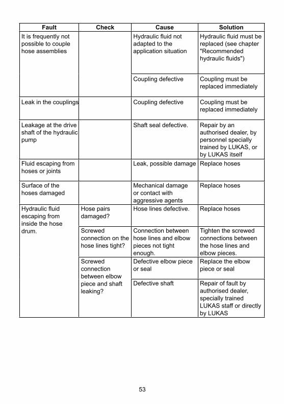
Fault Check Cause SolutionItisfrequentlynotpossibletocouplehoseassemblies
Hydraulicfluidnotadaptedtotheapplicationsituation
Hydraulicfluidmustbereplaced(seechapter"Recommendedhydraulicfluids")
Couplingdefective Couplingmustbereplacedimmediately
Leakinthecouplings Couplingdefective Couplingmustbereplacedimmediately
Leakageatthedriveshaftofthehydraulicpump
Shaftsealdefective. Repairbyanauthoriseddealer,bypersonnelspeciallytrainedbyLUKAS,orbyLUKASitself
Fluidescapingfromhosesorjoints
Leak,possibledamage Replacehoses
Surfaceofthehosesdamaged
Mechanicaldamageorcontactwithaggressiveagents
Replacehoses
Hydraulicfluidescapingfrominsidethehosedrum.
Hosepairsdamaged?
Hoselinesdefective. Replacehoses
Screwedconnectiononthehoselinestight?
Connectionbetweenhoselinesandelbowpiecesnottightenough.
Tightenthescrewedconnectionsbetweenthehoselinesandelbowpieces.
Screwedconnectionbetweenelbowpieceandshaftleaking?
Defectiveelbowpieceorseal
Replacetheelbowpieceorseal
Defectiveshaft Repairoffaultbyauthoriseddealer,speciallytrainedLUKASstaffordirectlybyLUKAS

54
NOTE: Incaseoffaultswhichaffectthecombustionengine,pleasealsoobservetheinstructionsintheseparateoperatinginstructionsoftheenginemanufacturer.
ContactanauthorisedLUKASdealerortheLUKASCustomerServiceDepartmentdirectlyifthemalfunctionscannotberectified.TheaddressfortheLUKASCustomerServicedepartmentis:
LUKAS Hydraulik GmbHA Unit of IDEX Corporation
Weinstraße39, D-91058ErlangenTel.: (+49)09131/698-348Fax.: (+49)09131/698-353
Hydraulicfluidescapingfromtheconnectionsbetweentheconnectionhosesandreelshaft
Connectionhosesdamaged?
Hoselinesdefective. Replacehoses
Screwedconnectiononthehoselinestight?
Hoselinesormalecouplingsnottightenough.
Tightenthescrewedconnectionsonthehoselinesormalecouplings.
Leakbetweenmalecouplingandshaft?
Malecouplingnottightenough
Tightenscrewedconnection.
Sealbetweenmalecouplingandshaftdefective?
Replaceseal.
Malecouplingdefective
Replacemalecoupling
Connectionbetweenhubandshaftleaking
Sealbetweenhubandshaftdefective.
Repairoffaultbyauthoriseddealer,speciallytrainedLUKASstaffordirectlybyLUKAS

55
13. Technical data
NOTE:The following tables contain only the technical data required for standardacceptance.AdditionaldataconcerningyourunitcanbeobtainedfromLUKASonrequest.The limitation of themax. fill quantity of the hydraulic tank results from the"operabilityatanincline"prescribedinthestandards.
Becauseallvaluesaresubjecttotolerances,theremaybesmalldifferencesbetweenthedataforyourdeviceandthedatainthefollowingtables!The values may also differ because of reading inaccuracies and/or tolerances in themeasuringequipmentused.
13.1 Power Unit13.1.1 Basic dimensions of the power unit (mm [inch])
Units without hose reel:

56
Units with hose reel (double hose):
Units with hose reel (mono hose):

57
1) HD = Highpressure 2) ND=Lowpressure 3) 1MPa=10bar
13.1.2 Technical data P 635 SG
Device type P 635 SGArticle number 81-53-40
Motor type 4-strokepetrolengine
Engine power rating[kW] 1,9/2,4[HP] 2.6 / 3.2
Engine speed[min-1]
3000/3800[rpm.]
Feed rate simultaneous (HD)1)
[l/min] 2x0,55/2x0,7[gal.-US/min] 2 x 0.15 / 2 x 0.19
Feed rate turbo (HD)1)
[l/min] 1x1,1/1x1,35[gal.-US/min] 1 x 0.29 / 1 x 0.36
Feed rate simultaneous (ND)2)
[l/min] 2x2,4/2x3,0[gal.-US/min] 2 x 0.63 / 2 x 0.79
Feed rate turbo (ND)2)
[l/min] 1x4,7/1x5,8[gal.-US/min] 1 x 1.24 / 1 x 1.53
Max. operating pressure (HD)1)
[MPa]3) 70[psi.] 10000
Max. operating pressure (ND)2)
[MPa]3) 14[psi.] 2000
Max. fill volume Hydraulicfluid
[l] 5,2[gal.-US] 1.37
Max. usable quantity Hydraulicfluid
[l] 5,0[gal.-US] 1.32
Max. fill volume Petrol
[l] 0,77[gal.-US] 0.20
Weight (incl.petrolandhydraulicfluid)
[kg] 32,5[lbs.] 71,7
Valve variants SimultaneousoperationMax. number of device connections 2Hose reel NO

58
1) HD = Highpressure 2) ND=Lowpressure 3) 1MPa=10bar
13.1.3 Technical data P 635 SG-DHR
Device type P 635 SG-DHRArticle number 81-54-43
Motor type 4-strokepetrolengine
Engine power rating[kW] 1,9/2,4[HP] 2.6 / 3.2
Engine speed[min-1]
3000/3800[rpm.]
Feed rate simultaneous (HD)1)
[l/min] 2x0,55/2x0,7[gal.-US/min] 2 x 0.15 / 2 x 0.19
Feed rate turbo (HD)1)
[l/min] 1x1,1/1x1,35[gal.-US/min] 1 x 0.29 / 1 x 0.36
Feed rate simultaneous (ND)2)
[l/min] 2x2,4/2x3,0[gal.-US/min] 2 x 0.63 / 2 x 0.79
Feed rate turbo (ND)2)
[l/min] 1x4,7/1x5,8[gal.-US/min] 1 x 1.24 / 1 x 1.53
Max. operating pressure (HD)1)
[MPa]3) 70[psi.] 10000
Max. operating pressure (ND)2)
[MPa]3) 14[psi.] 2000
Max. fill volume Hydraulicfluid
[l] 5,2[gal.-US] 1.37
Max. usable quantity Hydraulicfluid
[l] 5,0[gal.-US] 1.32
Max. fill volume Petrol
[l] 0,77[gal.-US] 0.20
Weight (incl.petrolandhydraulicfluid)
[kg] 72,5[lbs.] 159.8
Valve variants SimultaneousoperationMax. number of device connections 2
Hose reel (double hose)
[m] 2x20[ft] 2 x 66

59
1) HD = Highpressure 2) ND=Lowpressure 3) 1MPa=10bar
13.1.4 Technical data P 635 SG-DHR-COAX
Device type P 635 SG-DHR-COAXArticle number 81-54-40
Motor type 4-strokepetrolengine
Engine power rating[kW] 1,9/2,4[HP] 2.6 / 3.2
Engine speed[min-1]
3000/3800[rpm.]
Feed rate simultaneous (HD)1)
[l/min] 2x0,55/2x0,7[gal.-US/min] 2 x 0.15 / 2 x 0.19
Feed rate turbo (HD)1)
[l/min] 1x1,1/1x1,35[gal.-US/min] 1 x 0.29 / 1 x 0.36
Feed rate simultaneous (ND)2)
[l/min] 2x2,4/2x3,0[gal.-US/min] 2 x 0.63 / 2 x 0.79
Feed rate turbo (ND)2)
[l/min] 1x4,7/1x5,8[gal.-US/min] 1 x 1.24 / 1 x 1.53
Max. operating pressure (HD)1)
[MPa]3) 70[psi.] 10000
Max. operating pressure (ND)2)
[MPa]3) 14[psi.] 2000
Max. fill volume Hydraulicfluid
[l] 5,2[gal.-US] 1.37
Max. usable quantity Hydraulicfluid
[l] 5,0[gal.-US] 1.32
Max. fill volume Petrol
[l] 0,77[gal.-US] 0.20
Weight (incl.petrolandhydraulicfluid)
[kg] 74,3[lbs.] 163.8
Valve variants SimultaneousoperationMax. number of device connections 2
Hose reel (mono hose)
[m] 2x20[ft] 2 x 66
60
1) HD = Highpressure 2) ND=Lowpressure 3) 1MPa=10bar
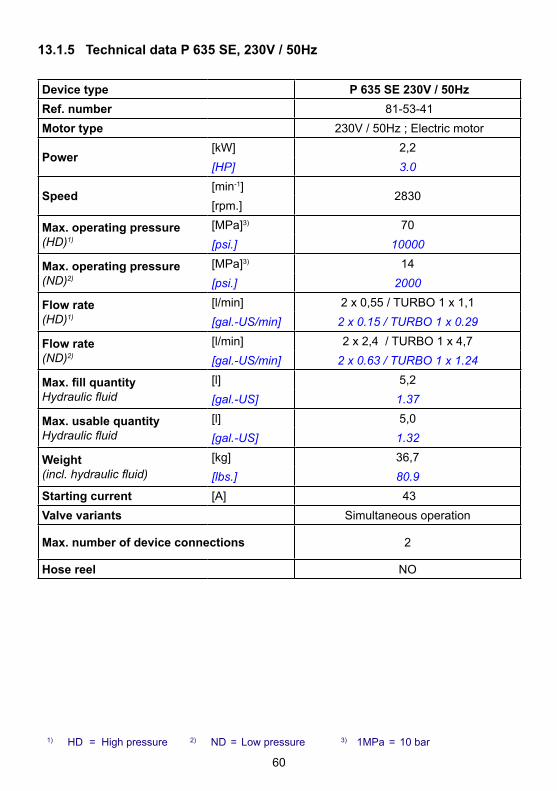
13.1.5 Technical data P 635 SE, 230V / 50Hz
Device type P 635 SE 230V / 50HzRef. number 81-53-41Motor type 230V/50Hz;Electricmotor
Power[kW] 2,2[HP] 3.0
Speed[min-1]
2830[rpm.]
Max. operating pressure (HD)1)
[MPa]3) 70[psi.] 10000
Max. operating pressure (ND)2)
[MPa]3) 14[psi.] 2000
Flow rate (HD)1)
[l/min] 2x0,55/TURBO1x1,1[gal.-US/min] 2 x 0.15 / TURBO 1 x 0.29
Flow rate (ND)2)
[l/min] 2x2,4/TURBO1x4,7[gal.-US/min] 2 x 0.63 / TURBO 1 x 1.24
Max. fill quantity Hydraulicfluid
[l] 5,2[gal.-US] 1.37
Max. usable quantity Hydraulicfluid
[l] 5,0[gal.-US] 1.32
Weight (incl.hydraulicfluid)
[kg] 36,7[lbs.] 80.9
Starting current [A] 43Valve variants Simultaneousoperation
Max. number of device connections 2
Hose reel NO

61
1) HD = Highpressure 2) ND=Lowpressure 3) 1MPa=10bar
13.1.6 Technical data P 635 SE, 230V / 60Hz
Device type P 635 SE 230V / 60HzRef. number 81-53-42Motor type 230V/60Hz;Electricmotor
Power[kW] 2,2[HP] 3.0
Speed[min-1]
3450[rpm.]
Max. operating pressure (HD)1)
[MPa]3) 70[psi.] 10000
Max. operating pressure (ND)2)
[MPa]3) 14[psi.] 2000
Flow rate (HD)1)
[l/min] 2x0,6/TURBO1x1,2[gal.-US/min] 2 x 0.16 / TURBO 1 x 0.32
Flow rate (ND)2)
[l/min] 2x2,8/TURBO1x5,5[gal.-US/min] 2 x 0.74 / TURBO 1 x 1.45
Max. fill quantity Hydraulicfluid
[l] 5,2[gal.-US] 1.37
Max. usable quantity Hydraulicfluid
[l] 5,0[gal.-US] 1.32
Weight (incl.hydraulicfluid)
[kg] 37,1[lbs.] 81.8
Starting current [A] 60Valve variants Simultaneousoperation
Max. number of device connections 2
Hose reel NO

62
1) HD = Highpressure 2) ND=Lowpressure 3) 1MPa=10bar
13.1.7 Technical data P 635 SE-DHR, 230V / 50Hz
Device type P 635 SE-DHR 230V / 50HzRef. number 81-54-44Motor type 230V/50Hz;Electricmotor
Power[kW] 2,2[HP] 3.0
Speed[min-1]
2830[rpm.]
Max. operating pressure (HD)1)
[MPa]3) 70[psi.] 10000
Max. operating pressure (ND)2)
[MPa]3) 14[psi.] 2000
Flow rate (HD)1)
[l/min] 2x0,55/TURBO1x1,1[gal.-US/min] 2 x 0.15 / TURBO 1 x 0.29
Flow rate (ND)2)
[l/min] 2x2,4/TURBO1x4,7[gal.-US/min] 2 x 0.63 / TURBO 1 x 1.24
Max. fill quantity Hydraulicfluid
[l] 5,2[gal.-US] 1.37
Max. usable quantity Hydraulicfluid
[l] 5,0[gal.-US] 1.32
Weight (incl.hydraulicfluid)
[kg] 76,7[lbs.] 169.1
Starting current [A] 43Valve variants Simultaneousoperation
Max. number of device connections 2
Hose reel (double hose)
[m] 2x20
[ft] 2 x 66

63
1) HD = Highpressure 2) ND=Lowpressure 3) 1MPa=10bar
13.1.8 Technical data P 635 SE-DHR, 230V / 60Hz
Device type P 635 SE-DHR 230V / 60HzRef. number 81-54-45Motor type 230V/60Hz;Electricmotor
Power[kW] 2,2[HP] 3.0
Speed[min-1]
3450[rpm.]
Max. operating pressure (HD)1)
[MPa]3) 70[psi.] 10000
Max. operating pressure (ND)2)
[MPa]3) 14[psi.] 2000
Flow rate (HD)1)
[l/min] 2x0,6/TURBO1x1,2[gal.-US/min] 2 x 0.16 / TURBO 1 x 0.32
Flow rate (ND)2)
[l/min] 2x2,8/TURBO1x5,5[gal.-US/min] 2 x 0.74 / TURBO 1 x 1.45
Max. fill quantity Hydraulicfluid
[l] 5,2[gal.-US] 1.37
Max. usable quantity Hydraulicfluid
[l] 5,0[gal.-US] 1.32
Weight (incl.hydraulicfluid)
[kg] 77,1[lbs.] 170.0
Starting current [A] 60Valve variants Simultaneousoperation
Max. number of device connections 2
Hose reel (double hose)
[m] 2x20
[ft] 2 x 66

64
1) HD = Highpressure 2) ND=Lowpressure 3) 1MPa=10bar
13.1.9 Technical data P 635 SE-DHR-COAX, 230V / 50Hz
Device type P 635 SE-DHR-COAX 230V / 50HzRef. number 81-54-41Motor type 230V/50Hz;Electricmotor
Power[kW] 2,2[HP] 3.0
Speed[min-1]
2830[rpm.]
Max. operating pressure (HD)1)
[MPa]3) 70[psi.] 10000
Max. operating pressure (ND)2)
[MPa]3) 14[psi.] 2000
Flow rate (HD)1)
[l/min] 2x0,55/TURBO1x1,1[gal.-US/min] 2 x 0.15 / TURBO 1 x 0.29
Flow rate (ND)2)
[l/min] 2x2,4/TURBO1x4,7[gal.-US/min] 2 x 0.63 / TURBO 1 x 1.24
Max. fill quantity Hydraulicfluid
[l] 5,2[gal.-US] 1.37
Max. usable quantity Hydraulicfluid
[l] 5,0[gal.-US] 1.32
Weight (incl.hydraulicfluid)
[kg] 78,5[lbs.] 173.1
Starting current [A] 43Valve variants Simultaneousoperation
Max. number of device connections 2
Hose reel (mono hose)
[m] 2x20
[ft] 2 x 66

65
1) HD = Highpressure 2) ND=Lowpressure 3) 1MPa=10bar
13.1.10 Technical data P 635 SE-DHR-COAX, 230V / 60Hz
Device type P 635 SE-DHR-COAX 230V / 60HzRef. number 81-54-42Motor type 230V/60Hz;Electricmotor
Power[kW] 2,2[HP] 3.0
Speed[min-1]
3450[rpm.]
Max. operating pressure (HD)1)
[MPa]3) 70[psi.] 10000
Max. operating pressure (ND)2)
[MPa]3) 14[psi.] 2000
Flow rate (HD)1)
[l/min] 2x0,6/TURBO1x1,2[gal.-US/min] 2 x 0.16 / TURBO 1 x 0.32
Flow rate (ND)2)
[l/min] 2x2,8/TURBO1x5,5[gal.-US/min] 2 x 0.74 / TURBO 1 x 1.45
Max. fill quantity Hydraulicfluid
[l] 5,2[gal.-US] 1.37
Max. usable quantity Hydraulicfluid
[l] 5,0[gal.-US] 1.32
Weight (incl.hydraulicfluid)
[kg] 78,9[lbs.] 173.9
Starting current [A] 60Valve variants Simultaneousoperation
Max. number of device connections 2
Hose reel (mono hose)
[m] 2x20[ft] 2 x 66

66
13.2 Noise emissions (Sound pressure level)
Device typeP 635 SG
P 635 SG-DHRP 635 SG-DHR-COAX
Speed [min-1]/[rpm.] 3000 3800Idle run(accordingtoEN) [dB(A)] 80 84Full load(accordingtoEN) [dB(A)] 84 88Idle run(accordingtoNFPA) [dB(A)] 73 77
Full load(accordingtoNFPA) [dB(A)] 77 80
Device type
P 635 SE 230V / 50Hz
P 635 SE-DHR 230V / 50Hz
P 635 SE-DHR-COAX 230V / 50Hz
P 635 SE 230V / 60Hz
P 635 SE-DHR 230V / 60Hz
P 635 SE-DHR-COAX 230V / 60Hz
Speed [min-1]/[rpm.] 2830 3450Idle run(accordingtoEN) [dB(A)] 75 76Full load(accordingtoEN) [dB(A)] 81 82Idle run(accordingtoNFPA) [dB(A)] 71 72Full load(accordingtoNFPA) [dB(A)] 75 76

67
Explanation of dual number noise emission values according to DIN EN 13204:2016-12Serialnumberofthemachine,operatingconditionsandothercharacteristicproperties:Model ...P 635 SG, P 635 SG-DHR, P 635 SG-DHR-COAX type...81-53-40,81-54-43,81-54-40,maximumworkingpressure...700bar,enginespeed....3800[min-1]/[rpm]INDICATEDDUALNUMBERNOISEEMISSIONVALUESaccordingtoENISO4871MeasuredA-ratedemissionsoundpressurelevelLpA,indB,referredto20μPa....88Measurementuncertainty,KpA,indB.....4MeasuredA-ratedemissionsoundpowerlevel(ifrequired)LWA,indB,referredto1pW....101Measurementuncertainty,KpA,indB.....4Values determined according to EN 13204, Appendix B, using basic standards ENISO3744andENISO11201.NOTE!Thesumofthemeasurednoiseemissionvaluesandtheassociatedmeasurementuncer-taintythatcanoccurduringthemeasurementrepresenttheupperlimitofthemeasuredvalues.
Explanation of dual number noise emission values according to DIN EN 13204:2016-12Serialnumberofthemachine,operatingconditionsandothercharacteristicproperties:Model ...P 635 SE 230V / 50Hz, P 635 SE-DHR 230V / 50Hz, P 635 SE-DHR-COAX 230V / 50Hz,type...81-53-41,81-54-44,81-54-41,maximumworkingpressure...700bar,enginespeed....2830[min-1]/[rpm]INDICATEDDUALNUMBERNOISEEMISSIONVALUESaccordingtoENISO4871MeasuredA-ratedemissionsoundpressurelevelLpA,indB,referredto20μPa....87Measurementuncertainty,KpA,indB.....4MeasuredA-ratedemissionsoundpowerlevel(ifrequired)LWA,indB,referredto1pW....102Measurementuncertainty,KpA,indB.....4Values determined according to EN 13204, Appendix B, using basic standards ENISO3744andENISO11201.NOTE!Thesumofthemeasurednoiseemissionvaluesandtheassociatedmeasurementuncer-taintythatcanoccurduringthemeasurementrepresenttheupperlimitofthemeasuredvalues.

68
13.3 Sparking plug
13.5 Fuel
Sparking plug type: CR5HSB(NGK) U16FSR-UB(DENSO)
Fuel: Lead-freepetrol ROZ91toROZ98
13.4 Sparking plug spanner
Universal joint sparking plug spanner with spanner size 16 mm (5/8 inch)
Explanation of dual number noise emission values according to DIN EN 13204:2016-12Serialnumberofthemachine,operatingconditionsandothercharacteristicproperties:Model ...P 635 SE 230V / 60Hz, P 635 SE-DHR 230V / 60Hz, P 635 SE-DHR-COAX 230V / 60Hz,type...81-53-42,81-54-45,81-54-42,maximumworkingpressure...700bar,enginespeed....3450[min-1]/[rpm]INDICATEDDUALNUMBERNOISEEMISSIONVALUESaccordingtoENISO4871MeasuredA-ratedemissionsoundpressurelevelLpA,indB,referredto20μPa....83Measurementuncertainty,KpA,indB.....4MeasuredA-ratedemissionsoundpowerlevel(ifrequired)LWA,indB,referredto1pW....97Measurementuncertainty,KpA,indB.....4Values determined according to EN 13204, Appendix B, using basic standards ENISO3744andENISO11201.NOTE!Thesumofthemeasurednoiseemissionvaluesandtheassociatedmeasurementuncer-taintythatcanoccurduringthemeasurementrepresenttheupperlimitofthemeasuredvalues.

69
13.7 Hydraulic fluid recommendation
13.8 Operating and storage temperature range
MineraloilDINISO6743-4forLUKAShydraulicequipmentandothers
Oiltemperaturerange Oildesignation Viscosityrating RemarksA -20....+55°C HM10 VG10
Oiltemperaturerange Oildesignation Viscosityrating RemarksA -4.0 .... +131°F HM10 VG10
recommendedrangeofviscosity:10...200mm²/s(10…200 cSt.)SuppliedwithHM10DINISO6743-4.
ATTENTION!Beforeyouusehydraulicfluidsfromadifferentmanufacturer,youmustcontactLUKASoranauthoriseddealer.
Operating temperature [°C]/[°F] -20 … +55 -4 … +131
Storage temperature (devicenotinoperation) [°C]/[°F] -30 … +60 -22 … +140
13.6 Engine oil

70
14. EC Declaration of Conformity

71
15. Notes

Please duly dispose of all packaging materials and removed items.
Subj
ect t
o ch
ange
© Copyright 2018 LUKAS Hydraulik GmbHP635_manual_175635085_en.indd
LUKAS Hydraulik GmbHA Unit of IDEX Corporation
Weinstraße 39, D-91058 ErlangenTel.: 0049 (0) 91 31 / 698 - 0Fax.: 0049 (0) 91 31 / 698 - 394e-mail: [email protected]
Made in GERMANY
WARNING/CAUTION! Beforeconnectingtheequipment,makesurethatall the components used are suitable for the
maximum operating pressure of the hydraulic unit!Incasesofdoubt,you must consult LUKAS
directlybeforeconnectingtheequipment!