instruction manual for sp link - selectronic australiadownload.selectronic.com.au/manuals/oi0005_13...
TRANSCRIPT
Instruction Manual forSP LINK
Configuration and monitoring forSP PRO AU and GO series
SP LINK | Contents
Contents
Contents 2Using This Manual 3Overview 4
Using SP LINK 4System Requirements for SP LINK 5Firmware Version 8.1 onwards 5Glossary of Terms 5Getting Started with SP LINK 6HELP! 6SP LINK Easy Start Guide 7Site Configuration Wizard 8Select Battery Configuration 8Source of Renewables 9Select Unit Application 9Summary of Settings 9Entering extra Details and Saving 9Sending Configuration to the Inverter 9Advanced Configuration 10Preparing a new site 10Saving a new site 11Manually Preparing a new configuration 12Saving a new configuration 14Connecting to the SP PRO 14Configuring the SP PRO 15Connection Settings 16Customising SP LINK to suit the site 17Performance Data Retrieval 18Performance Data Viewer 19
Configuration Settings 20Quick Start 21Inverter Settings 22Battery Settings 24Charger Settings 25AC Source Settings 28AC Input 28Generator Auto Start 30Generator Schedule Start 34Generator Control Settings 37Solar Hybrid Control Settings 39System Settings 42Input and Output Settings 45Shunts Settings 50Expansion Card Wiring Diagram 51Save and Configure Settings 51
Performance Monitoring 52Customer Interface 53Integrator / User Interface 53Quick View 54Data View 56Now Tab 56STATUS 56DC 57AC Source 57Inverter AC 57System regulation status 58Today Tab 59DC totals 59AC totals 59DC Peak 59AC coupled SOLAR 59DC History Tab 60AC History Tab 63Technical Data Tab 65Expansion Card Wiring Diagram Tab 68
Service Settings 70Time and date 71Battery SoC 71Expansion Card 71Settings Passcode 71Zero Shunts 72Fan Type 72AC Safety Monitor 72Request Battery Equalise 73Login Password 73AC Solar Link Test 73Setting Charge Efficiency Index 73Setting For Poor Grid Quality 73
Appendix One Alert Messages 74
SP LINK | Using This Manual
Using This Manual
While every attempt has been made to ensure this manual is as self explanatory and clear as possible, there are some technical issues and safety warnings that require thorough understanding. It is extremely important that you and your integrator/installer follow all of the instructions set out in this document; failure to do so may void the warranty and stop you from gaining the full benefits that we know this product can provide.
A PDF copy of this manual may be downloaded from the Selectronic web site www.selectronic.com.au and is also included within the Help menu of the SP LINK software.
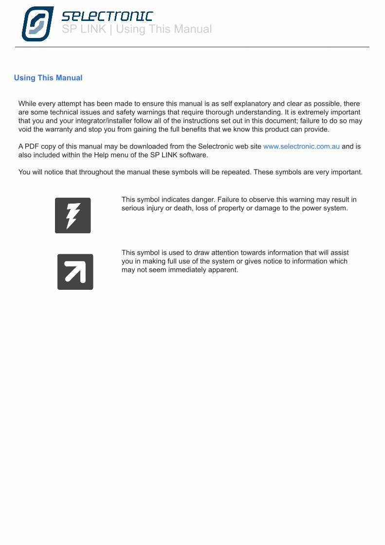
You will notice that throughout the manual these symbols will be repeated. These symbols are very important.
This symbol indicates danger. Failure to observe this warning may result in serious injury or death, loss of property or damage to the power system.
This symbol is used to draw attention towards information that will assist you in making full use of the system or gives notice to information which may not seem immediately apparent.
SP LINK | Using SP LINK
4 | Doc #OI0005 Rev13 2016
Using SP LINK
Overview
“SP LINK is the pathway to the real power of the SP PRO AU and GO” SP PRO AU and GO series of inverters are really many products in one. Simply unpack the unit, mount it on a wall, connect the appropriate cables – and you’ve got power using the following default settings; • Off Grid • AC Source size is equal to the power output of the SP PRO model you are using • Sealed Batteries • No State of Charge readings, voltage only.
To go further and unlock all the features of the SP PRO simply load the SP LINK software (found on the supplied USB stick or download from www.selectronic.com.au) onto a PC computer. We suggest these steps are done before heading to the installation site.
SP LINK | Using SP LINK
Doc #OI0005 Rev13 2016 | 5
PERFORMANCE REQUIREMENTS:
• Microsoft Windows XP SP3, Vista SP1, 7, 8, 8.1, 10 Other operating systems not supported.• 30 MB hard disk space • If Microsoft .NET 4.0 Framework is not already installed then approx. 850 MB of additional disk space will be required. • Adobe Reader - 100 MB hard disk space• 1 GHz Pentium or faster processor. • 512 MB RAM • USB Port
PERFORMANCE VIEWER REQUIREMENTS
Microsoft Excel 2003 or higher. Office 365 not supported.
System Requirements for SP LINKThe system requirements include:
DC Coupled system Refers to when the Solar is connected to the DC side of the inverter system through a Solar Controller.
AC Coupled system Refers to when the Solar is connected to AC Side of the inverter system via a separate Grid Tie inverter.
Solar Hybrid Refers to a system which is connected to the electricity grid and also utilises batteries in the system.
AC Source The primary AC input that is connected to the SP PRO, e.g., Grid, Auto start Generator, Shore Power.
Site File An SP LINK file which is set up for a particular site that you will need to connect to.
Configuration File Effectively a subset of a Site File which contains all of the settings that you want to load into the SP PRO
Solar Array A collection of Solar Panels.
PV Photo voltaic solar power .
State of Charge (SoC) Referring to the battery condition. 80% SoC means the battery is 20% from full.
Sealed Battery A lead acid battery with no access to the electrolyte - either valve regulated or gel. No hydrogen gas discharge during normal operation.
Flooded Battery A lead acid battery with access caps for maintaining the electrolyte - replacing water lost during recharge operations. Hydrogen gas discharged during normal recharge operation.
Firmware Version 8.1 onwardsThis SP LINK manual details configuration parameters and options found in the included version of SP PRO series firmware. Some parameters are no longer supported and are not detailed within this manual. Please refer to prior SP LINK manual for details of unsupported features.
SP LINK is fully backward compatible with all prior versions of SP PRO series firmware.
Glossary of TermsTerms used within this manual
SP LINK | Using SP LINK
6 | Doc #OI0005 Rev13 2016
Getting Started with SP LINK
You will find SP LINK and other helpful documents contained on the USB stick supplied with the SP PRO, it is good practise to check at www.selectronic.com.au for the latest version of SP LINK.
After loading SP LINK onto the computer, you can now begin to use SP LINK. However, we do warn that to achieve the best performance from the system, configuration should be done by an experienced system designer. For maximum warranty in Australia, you will need to employ the services of a Selectronic Accredited Integrator. For full warranty terms and conditions please see the warranty supplied with the SP PRO inverter.
To get started, you do not have to be connected to an SP PRO inverter. Once you have loaded SP LINK onto the computer, you can pre-configure and store on the computer the site information and configuration settings. These are then ready to transfer into the SP PRO inverter after it is installed.
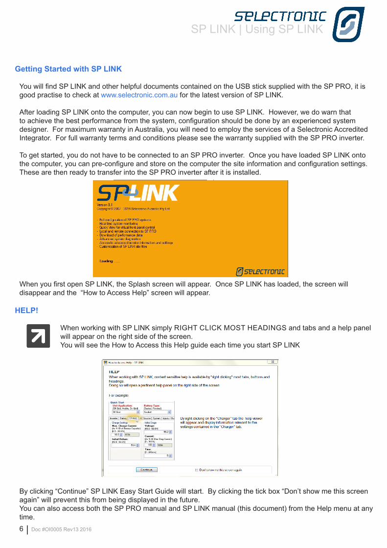
When you first open SP LINK, the Splash screen will appear. Once SP LINK has loaded, the screen will disappear and the “How to Access Help” screen will appear.
HELP!
When working with SP LINK simply RIGHT CLICK MOST HEADINGS and tabs and a help panel will appear on the right side of the screen.You will see the How to Access this Help guide each time you start SP LINK
By clicking “Continue” SP LINK Easy Start Guide will start. By clicking the tick box “Don’t show me this screen again” will prevent this from being displayed in the future.You can also access both the SP PRO manual and SP LINK manual (this document) from the Help menu at any time.
SP LINK | Using SP LINK
Doc #OI0005 Rev13 2016 | 7
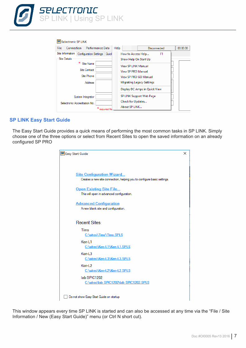
SP LINK Easy Start Guide
The Easy Start Guide provides a quick means of performing the most common tasks in SP LINK. Simply choose one of the three options or select from Recent Sites to open the saved information on an already configured SP PRO
This window appears every time SP LINK is started and can also be accessed at any time via the “File / Site Information / New (Easy Start Guide)” menu (or Ctrl N short cut).
SP LINK | Using SP LINK
8 | Doc #OI0005 Rev13 2016
Site Configuration Wizard
Provides a quick and easy way to configure a SP PRO in a new installation. The configuration information can be created and saved to a Site file ready for sending to the inverter as required.
The wizard steps through the configuration process and informs the system designer at each step of any invalid configuration or limitations of the chosen components.
The wizard is self explanatory. A description of each screen is given below
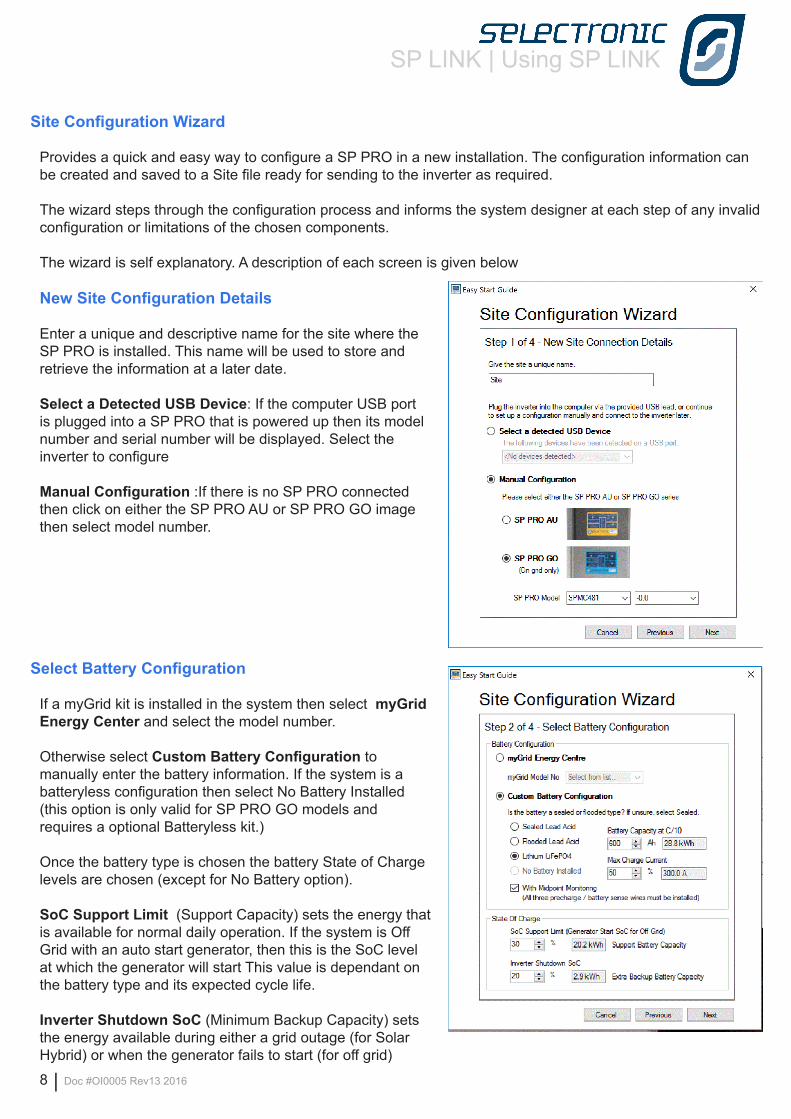
New Site Configuration Details
Enter a unique and descriptive name for the site where the SP PRO is installed. This name will be used to store and retrieve the information at a later date.
Select a Detected USB Device: If the computer USB port is plugged into a SP PRO that is powered up then its model number and serial number will be displayed. Select the inverter to configure
Manual Configuration :If there is no SP PRO connected then click on either the SP PRO AU or SP PRO GO image then select model number.
Select Battery Configuration
If a myGrid kit is installed in the system then select myGrid Energy Center and select the model number.
Otherwise select Custom Battery Configuration to manually enter the battery information. If the system is a batteryless configuration then select No Battery Installed (this option is only valid for SP PRO GO models and requires a optional Batteryless kit.)
Once the battery type is chosen the battery State of Charge levels are chosen (except for No Battery option).
SoC Support Limit (Support Capacity) sets the energy that is available for normal daily operation. If the system is Off Grid with an auto start generator, then this is the SoC level at which the generator will start This value is dependant on the battery type and its expected cycle life.
Inverter Shutdown SoC (Minimum Backup Capacity) sets the energy available during either a grid outage (for Solar Hybrid) or when the generator fails to start (for off grid)
SP LINK | Using SP LINK
Doc #OI0005 Rev13 2016 | 9
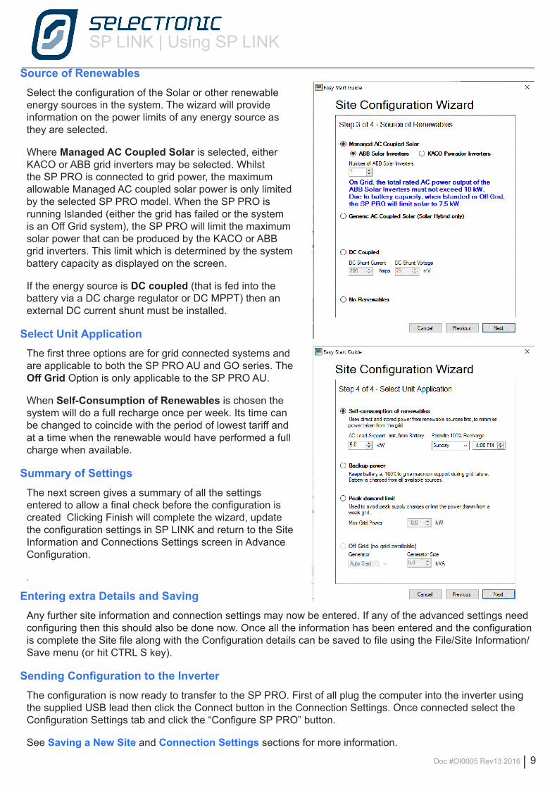
Source of RenewablesSelect the configuration of the Solar or other renewable energy sources in the system. The wizard will provide information on the power limits of any energy source as they are selected.
Where Managed AC Coupled Solar is selected, either KACO or ABB grid inverters may be selected. Whilst the SP PRO is connected to grid power, the maximum allowable Managed AC coupled solar power is only limited by the selected SP PRO model. When the SP PRO is running Islanded (either the grid has failed or the system is an Off Grid system), the SP PRO will limit the maximum solar power that can be produced by the KACO or ABB grid inverters. This limit which is determined by the system battery capacity as displayed on the screen.
If the energy source is DC coupled (that is fed into the battery via a DC charge regulator or DC MPPT) then an external DC current shunt must be installed.
Select Unit ApplicationThe first three options are for grid connected systems and are applicable to both the SP PRO AU and GO series. The Off Grid Option is only applicable to the SP PRO AU.
When Self-Consumption of Renewables is chosen the system will do a full recharge once per week. Its time can be changed to coincide with the period of lowest tariff and at a time when the renewable would have performed a full charge when available.
Summary of SettingsThe next screen gives a summary of all the settings entered to allow a final check before the configuration is created Clicking Finish will complete the wizard, update the configuration settings in SP LINK and return to the Site Information and Connections Settings screen in Advance Configuration.
.
Entering extra Details and Saving Any further site information and connection settings may now be entered. If any of the advanced settings need configuring then this should also be done now. Once all the information has been entered and the configuration is complete the Site file along with the Configuration details can be saved to file using the File/Site Information/Save menu (or hit CTRL S key).
Sending Configuration to the InverterThe configuration is now ready to transfer to the SP PRO. First of all plug the computer into the inverter using the supplied USB lead then click the Connect button in the Connection Settings. Once connected select the Configuration Settings tab and click the “Configure SP PRO” button.
See Saving a New Site and Connection Settings sections for more information.
SP LINK | Using SP LINK
10 | Doc #OI0005 Rev13 2016
Advanced Configuration
Advanced configuration gives access to all the functions of SP LINK allowing the installer to create a Site file and manual configuration that starts with either the default settings or settings created from the Site Configuration Wizard.
The Quick View and Data View tabs read all the information from the connected SP PRO to assist the installer in commissioning and diagnosing the System. Please remember that if help is require for a function in SP LINK hover the cursor over the heading or right click on the heading to be taken to the relevant section of the SP LINK manual.
Preparing a new site
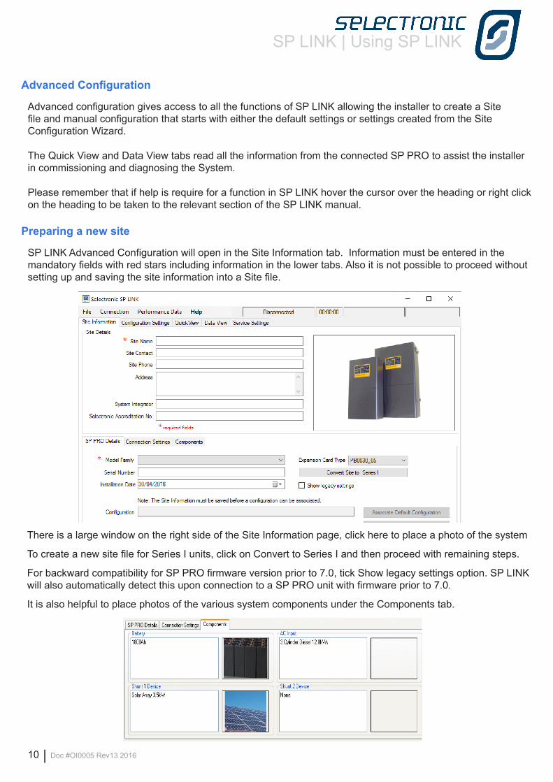
SP LINK Advanced Configuration will open in the Site Information tab. Information must be entered in the mandatory fields with red stars including information in the lower tabs. Also it is not possible to proceed without setting up and saving the site information into a Site file.
There is a large window on the right side of the Site Information page, click here to place a photo of the system
To create a new site file for Series I units, click on Convert to Series I and then proceed with remaining steps.
For backward compatibility for SP PRO firmware version prior to 7.0, tick Show legacy settings option. SP LINK will also automatically detect this upon connection to a SP PRO unit with firmware prior to 7.0.
It is also helpful to place photos of the various system components under the Components tab.
SP LINK | Using SP LINK
Doc #OI0005 Rev13 2016 | 11
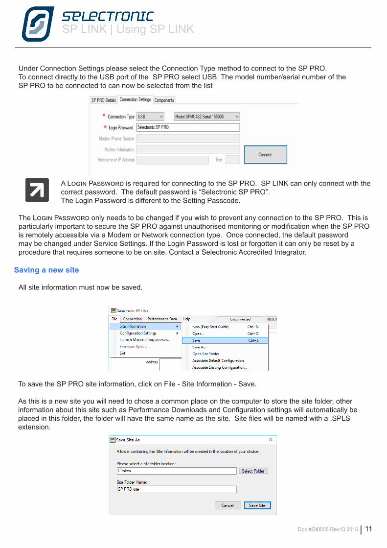
Under Connection Settings please select the Connection Type method to connect to the SP PRO. To connect directly to the USB port of the SP PRO select USB. The model number/serial number of the SP PRO to be connected to can now be selected from the list
A Login Password is required for connecting to the SP PRO. SP LINK can only connect with the correct password. The default password is “Selectronic SP PRO”.The Login Password is different to the Setting Passcode.
The Login Password only needs to be changed if you wish to prevent any connection to the SP PRO. This is particularly important to secure the SP PRO against unauthorised monitoring or modification when the SP PRO is remotely accessible via a Modem or Network connection type. Once connected, the default password may be changed under Service Settings. If the Login Password is lost or forgotten it can only be reset by a procedure that requires someone to be on site. Contact a Selectronic Accredited Integrator.
Saving a new site
All site information must now be saved.
To save the SP PRO site information, click on File - Site Information - Save.
As this is a new site you will need to chose a common place on the computer to store the site folder, other information about this site such as Performance Downloads and Configuration settings will automatically be placed in this folder, the folder will have the same name as the site. Site files will be named with a .SPLS extension.
SP LINK | Using SP LINK
12 | Doc #OI0005 Rev13 2016
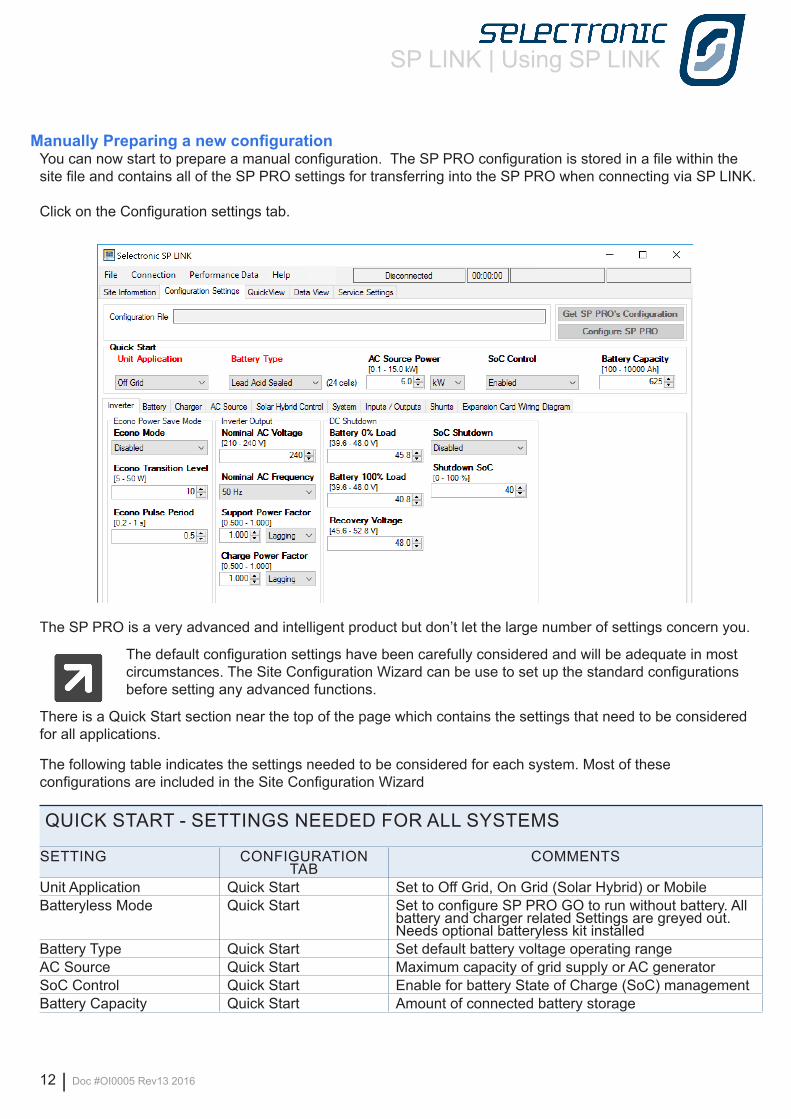
Manually Preparing a new configurationYou can now start to prepare a manual configuration. The SP PRO configuration is stored in a file within the site file and contains all of the SP PRO settings for transferring into the SP PRO when connecting via SP LINK.
Click on the Configuration settings tab.
The SP PRO is a very advanced and intelligent product but don’t let the large number of settings concern you.
The default configuration settings have been carefully considered and will be adequate in most circumstances. The Site Configuration Wizard can be use to set up the standard configurations before setting any advanced functions.
There is a Quick Start section near the top of the page which contains the settings that need to be considered for all applications.
The following table indicates the settings needed to be considered for each system. Most of these configurations are included in the Site Configuration Wizard
QUICK START - SETTINGS NEEDED FOR ALL SYSTEMS
SETTING CONFIGURATION TAB
COMMENTS
Unit Application Quick Start Set to Off Grid, On Grid (Solar Hybrid) or MobileBatteryless Mode Quick Start Set to configure SP PRO GO to run without battery. All
battery and charger related Settings are greyed out. Needs optional batteryless kit installed
Battery Type Quick Start Set default battery voltage operating rangeAC Source Quick Start Maximum capacity of grid supply or AC generatorSoC Control Quick Start Enable for battery State of Charge (SoC) managementBattery Capacity Quick Start Amount of connected battery storage
SP LINK | Using SP LINK
Doc #OI0005 Rev13 2016 | 13
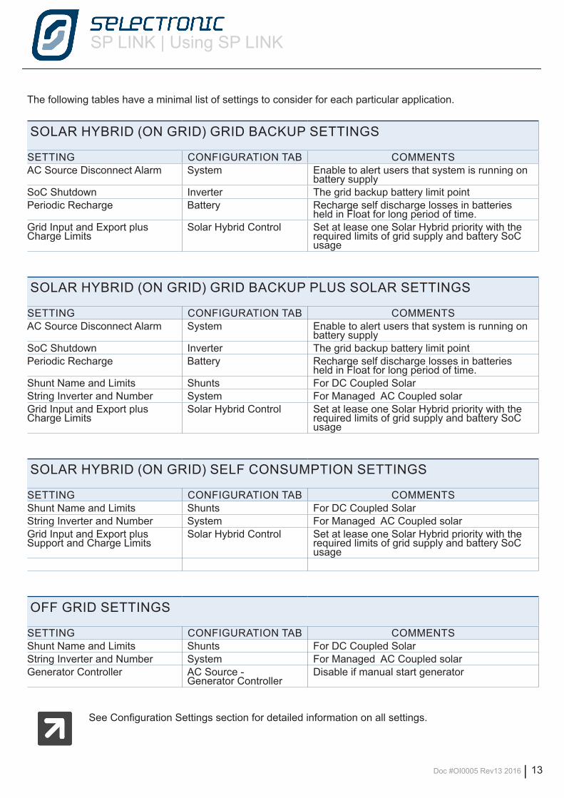
The following tables have a minimal list of settings to consider for each particular application.
SOLAR HYBRID (ON GRID) GRID BACKUP SETTINGS
SETTING CONFIGURATION TAB COMMENTSAC Source Disconnect Alarm System Enable to alert users that system is running on
battery supplySoC Shutdown Inverter The grid backup battery limit pointPeriodic Recharge Battery Recharge self discharge losses in batteries
held in Float for long period of time.Grid Input and Export plus Charge Limits
Solar Hybrid Control Set at lease one Solar Hybrid priority with the required limits of grid supply and battery SoC usage
SOLAR HYBRID (ON GRID) GRID BACKUP PLUS SOLAR SETTINGS
SETTING CONFIGURATION TAB COMMENTSAC Source Disconnect Alarm System Enable to alert users that system is running on
battery supplySoC Shutdown Inverter The grid backup battery limit pointPeriodic Recharge Battery Recharge self discharge losses in batteries
held in Float for long period of time.Shunt Name and Limits Shunts For DC Coupled SolarString Inverter and Number System For Managed AC Coupled solarGrid Input and Export plus Charge Limits
Solar Hybrid Control Set at lease one Solar Hybrid priority with the required limits of grid supply and battery SoC usage
SOLAR HYBRID (ON GRID) SELF CONSUMPTION SETTINGS
SETTING CONFIGURATION TAB COMMENTSShunt Name and Limits Shunts For DC Coupled SolarString Inverter and Number System For Managed AC Coupled solarGrid Input and Export plus Support and Charge Limits
Solar Hybrid Control Set at lease one Solar Hybrid priority with the required limits of grid supply and battery SoC usage
OFF GRID SETTINGS
SETTING CONFIGURATION TAB COMMENTSShunt Name and Limits Shunts For DC Coupled SolarString Inverter and Number System For Managed AC Coupled solarGenerator Controller AC Source -
Generator ControllerDisable if manual start generator
See Configuration Settings section for detailed information on all settings.
SP LINK | Using SP LINK
14 | Doc #OI0005 Rev13 2016
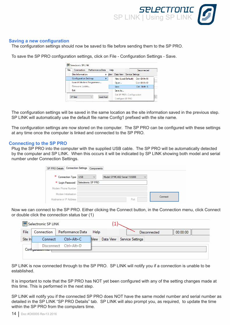
Saving a new configurationThe configuration settings should now be saved to file before sending them to the SP PRO.
To save the SP PRO configuration settings, click on File - Configuration Settings - Save.
The configuration settings will be saved in the same location as the site information saved in the previous step. SP LINK will automatically use the default file name Config1 prefixed with the site name.
The configuration settings are now stored on the computer. The SP PRO can be configured with these settings at any time once the computer is linked and connected to the SP PRO.
Connecting to the SP PROPlug the SP PRO into the computer with the supplied USB cable. The SP PRO will be automatically detected by the computer and SP LINK. When this occurs it will be indicated by SP LINK showing both model and serial number under Connection Settings.
Now we can connect to the SP PRO. Either clicking the Connect button, in the Connection menu, click Connect or double click the connection status bar (1)
SP LINK is now connected through to the SP PRO. SP LINK will notify you if a connection is unable to be established.
It is important to note that the SP PRO has NOT yet been configured with any of the setting changes made at this time. This is performed in the next step.
SP LINK will notify you if the connected SP PRO does NOT have the same model number and serial number as detailed in the SP LINK “SP PRO Details” tab. SP LINK will also prompt you, as required, to update the time within the SP PRO from the computers time.
SP LINK | Using SP LINK
Doc #OI0005 Rev13 2016 | 15
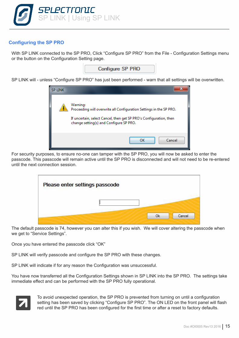
Configuring the SP PRO
With SP LINK connected to the SP PRO, Click “Configure SP PRO” from the File - Configuration Settings menu or the button on the Configuration Setting page.
SP LINK will - unless “Configure SP PRO” has just been performed - warn that all settings will be overwritten.
For security purposes, to ensure no-one can tamper with the SP PRO, you will now be asked to enter the passcode. This passcode will remain active until the SP PRO is disconnected and will not need to be re-entered until the next connection session.
The default passcode is 74, however you can alter this if you wish. We will cover altering the passcode when we get to “Service Settings”.
Once you have entered the passcode click “OK”
SP LINK will verify passcode and configure the SP PRO with these changes.
SP LINK will indicate if for any reason the Configuration was unsuccessful.
You have now transferred all the Configuration Settings shown in SP LINK into the SP PRO. The settings take immediate effect and can be performed with the SP PRO fully operational.
To avoid unexpected operation, the SP PRO is prevented from turning on until a configuration setting has been saved by clicking “Configure SP PRO”. The ON LED on the front panel will flash red until the SP PRO has been configured for the first time or after a reset to factory defaults.
SP LINK | Using SP LINK
16 | Doc #OI0005 Rev13 2016
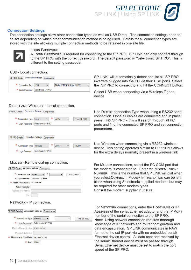
For Modem connections, select the PC COM port that the modem is connected to. Enter the Modem Phone Number. This is the number that SP LINK will dial when you select Connect. Modem Initialisation can be left blank when using Selectronic supplied modems but may be required for other modem types.Consult the modem supplier if unsure.
Connection SettingsThe connection settings allow other connection types as well as USB Direct. The connection settings need to be set depending on which other communication method is being used. Details for all connection types are stored with the site allowing multiple connection methods to be retained in one site file.
Login PasswordA Login Password is required for connecting to the SP PRO. SP LINK can only connect through to the SP PRO with the correct password. The default password is “Selectronic SP PRO”. This is different to the setting passcode.
Modem - Remote dial-up connection.
Network - IP connection.For Network connections, enter the Hostname or IP Address of the serial/Ethernet adaptor and the IP Port number of the serial connection to the SP PRO.Note: Using network connection requires thorough knowledge of IP networks and router configuration and data encapsulation. SP LINK communicates in RAW format to the set IP port via with no embedded serial/Ethernet device control. All data sent and received by the serial/Ethernet device must be passed through. Serial/Ethernet device must be set to match the port speed of the SP PRO.
Use Direct connection Type when using a RS232 serial connection. Once all cables are connected and in place, press Find SP PRO - this will search through all PC ports and find the connected SP PRO and set connection parameters.
Use Wireless when connecting via a RS232 wireless device. This setting operates similar to Direct but allows for the extra delays normally present in a wireless link
Direct and Wireless - Local connection.
SP LINK will automatically detect and list all SP PRO inverters plugged into the PC via their USB ports. Select the SP PRO to connect to and hit the CONNECT button.
Select USB when connecting via a Wireless Zigbee device
USB - Local connection.
SP LINK | Using SP LINK
Doc #OI0005 Rev13 2016 | 17
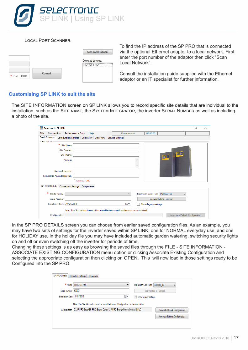
Local Port Scanner.To find the IP address of the SP PRO that is connected via the optional Ethernet adaptor to a local network. First enter the port number of the adaptor then click “Scan Local Network”.
Consult the installation guide supplied with the Ethernet adaptor or an IT specialist for further information.
Customising SP LINK to suit the site
The SITE INFORMATION screen on SP LINK allows you to record specific site details that are individual to the installation, such as the Site name, the System Integrator, the inverter Serial Number as well as including a photo of the site.
In the SP PRO DETAILS screen you can choose from earlier saved configuration files. As an example, you may have two sets of settings for the inverter saved within SP LINK; one for NORMAL everyday use, and one for HOLIDAY use. In the holiday file you may have included automatic garden watering, switching security lights on and off or even switching off the inverter for periods of time. Changing these settings is as easy as browsing the saved files through the FILE - SITE INFORMATION - ASSOCIATE EXISTING CONFIGURATION menu option or clicking Associate Existing Configuration and selecting the appropriate configuration then clicking on OPEN. This will now load in those settings ready to be Configured into the SP PRO.
SP LINK | Using SP LINK
18 | Doc #OI0005 Rev13 2016
Performance Data Retrieval
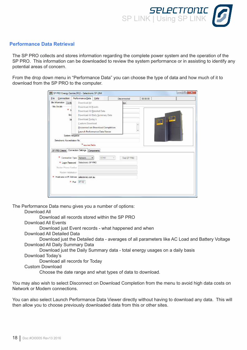
The SP PRO collects and stores information regarding the complete power system and the operation of the SP PRO. This information can be downloaded to review the system performance or in assisting to identify any potential areas of concern.
From the drop down menu in “Performance Data” you can choose the type of data and how much of it to download from the SP PRO to the computer.
The Performance Data menu gives you a number of options: Download All Download all records stored within the SP PRO Download All Events Download just Event records - what happened and when Download All Detailed Data Download just the Detailed data - averages of all parameters like AC Load and Battery Voltage Download All Daily Summary Data Download just the Daily Summary data - total energy usages on a daily basis Download Today’s Download all records for Today Custom Download Choose the date range and what types of data to download.
You may also wish to select Disconnect on Download Completion from the menu to avoid high data costs on Network or Modem connections.
You can also select Launch Performance Data Viewer directly without having to download any data. This will then allow you to choose previously downloaded data from this or other sites.
SP LINK | Using SP LINK
Doc #OI0005 Rev13 2016 | 19
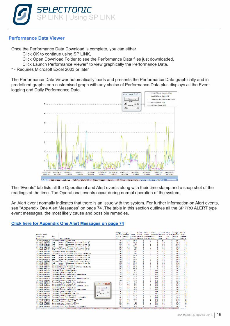
Performance Data Viewer
Once the Performance Data Download is complete, you can either Click OK to continue using SP LINK, Click Open Download Folder to see the Performance Data files just downloaded, Click Launch Performance Viewer* to view graphically the Performance Data.* - Requires Microsoft Excel 2003 or later
The Performance Data Viewer automatically loads and presents the Performance Data graphically and in predefined graphs or a customised graph with any choice of Performance Data plus displays all the Event logging and Daily Performance Data.
The “Events” tab lists all the Operational and Alert events along with their time stamp and a snap shot of the readings at the time. The Operational events occur during normal operation of the system.
An Alert event normally indicates that there is an issue with the system. For further information on Alert events, see “Appendix One Alert Messages” on page 74 .The table in this section outlines all the SP PRO ALERT type event messages, the most likely cause and possible remedies.
Click here for Appendix One Alert Messages on page 74
SP LINK | Configuration Settings
20 | Doc #OI0005 Rev13 2016
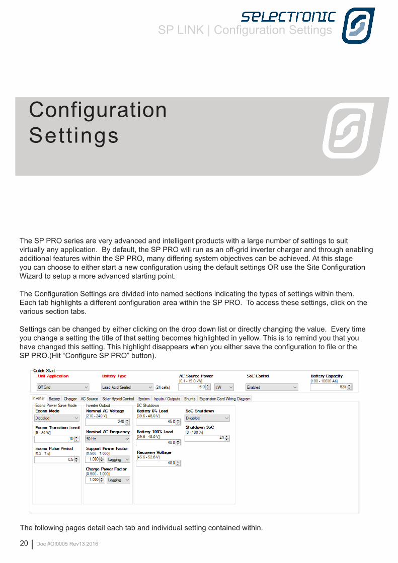
The SP PRO series are very advanced and intelligent products with a large number of settings to suit virtually any application. By default, the SP PRO will run as an off-grid inverter charger and through enabling additional features within the SP PRO, many differing system objectives can be achieved. At this stage you can choose to either start a new configuration using the default settings OR use the Site Configuration Wizard to setup a more advanced starting point.
The Configuration Settings are divided into named sections indicating the types of settings within them. Each tab highlights a different configuration area within the SP PRO. To access these settings, click on the various section tabs.
Settings can be changed by either clicking on the drop down list or directly changing the value. Every time you change a setting the title of that setting becomes highlighted in yellow. This is to remind you that you have changed this setting. This highlight disappears when you either save the configuration to file or the SP PRO.(Hit “Configure SP PRO” button).
The following pages detail each tab and individual setting contained within.
Configuration Settings
SP LINK | Configuration Settings
Doc #OI0005 Rev13 2016 | 21
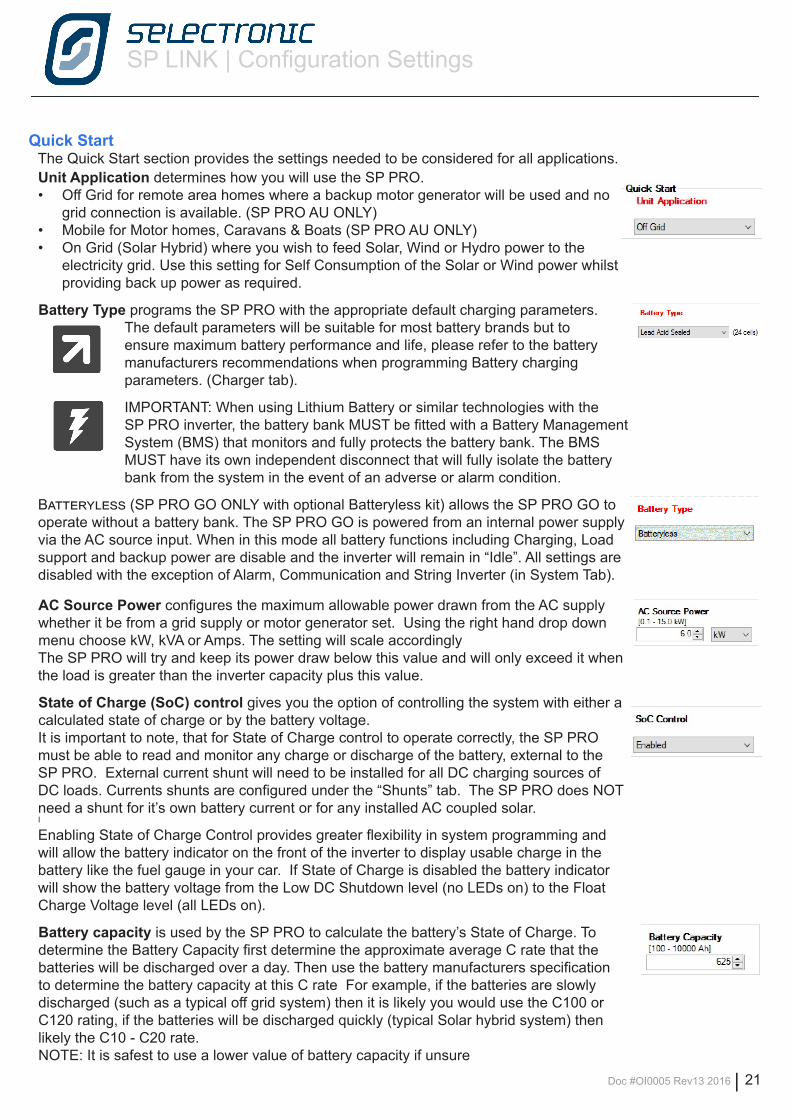
Unit Application determines how you will use the SP PRO.• Off Grid for remote area homes where a backup motor generator will be used and no
grid connection is available. (SP PRO AU ONLY)• Mobile for Motor homes, Caravans & Boats (SP PRO AU ONLY)• On Grid (Solar Hybrid) where you wish to feed Solar, Wind or Hydro power to the
electricity grid. Use this setting for Self Consumption of the Solar or Wind power whilst providing back up power as required.
Battery Type programs the SP PRO with the appropriate default charging parameters.The default parameters will be suitable for most battery brands but to ensure maximum battery performance and life, please refer to the battery manufacturers recommendations when programming Battery charging parameters. (Charger tab).
IMPORTANT: When using Lithium Battery or similar technologies with the SP PRO inverter, the battery bank MUST be fitted with a Battery Management System (BMS) that monitors and fully protects the battery bank. The BMS MUST have its own independent disconnect that will fully isolate the battery bank from the system in the event of an adverse or alarm condition.
Batteryless (SP PRO GO ONLY with optional Batteryless kit) allows the SP PRO GO to operate without a battery bank. The SP PRO GO is powered from an internal power supply via the AC source input. When in this mode all battery functions including Charging, Load support and backup power are disable and the inverter will remain in “Idle”. All settings are disabled with the exception of Alarm, Communication and String Inverter (in System Tab).
AC Source Power configures the maximum allowable power drawn from the AC supply whether it be from a grid supply or motor generator set. Using the right hand drop down menu choose kW, kVA or Amps. The setting will scale accordingly The SP PRO will try and keep its power draw below this value and will only exceed it when the load is greater than the inverter capacity plus this value.
State of Charge (SoC) control gives you the option of controlling the system with either a calculated state of charge or by the battery voltage. It is important to note, that for State of Charge control to operate correctly, the SP PRO must be able to read and monitor any charge or discharge of the battery, external to the SP PRO. External current shunt will need to be installed for all DC charging sources of DC loads. Currents shunts are configured under the “Shunts” tab. The SP PRO does NOT need a shunt for it’s own battery current or for any installed AC coupled solar.I
Enabling State of Charge Control provides greater flexibility in system programming and will allow the battery indicator on the front of the inverter to display usable charge in the battery like the fuel gauge in your car. If State of Charge is disabled the battery indicator will show the battery voltage from the Low DC Shutdown level (no LEDs on) to the Float Charge Voltage level (all LEDs on).
Battery capacity is used by the SP PRO to calculate the battery’s State of Charge. To determine the Battery Capacity first determine the approximate average C rate that the batteries will be discharged over a day. Then use the battery manufacturers specification to determine the battery capacity at this C rate For example, if the batteries are slowly discharged (such as a typical off grid system) then it is likely you would use the C100 or C120 rating, if the batteries will be discharged quickly (typical Solar hybrid system) then likely the C10 - C20 rate.NOTE: It is safest to use a lower value of battery capacity if unsure
Quick StartThe Quick Start section provides the settings needed to be considered for all applications.
SP LINK | Configuration Settings
22 | Doc #OI0005 Rev13 2016
Inverter Settings
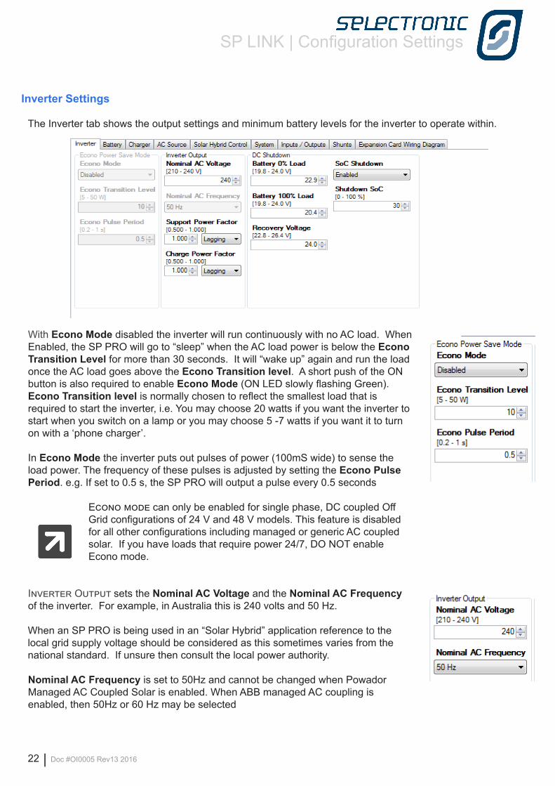
The Inverter tab shows the output settings and minimum battery levels for the inverter to operate within.
With Econo Mode disabled the inverter will run continuously with no AC load. When Enabled, the SP PRO will go to “sleep” when the AC load power is below the Econo Transition Level for more than 30 seconds. It will “wake up” again and run the load once the AC load goes above the Econo Transition level. A short push of the ON button is also required to enable Econo Mode (ON LED slowly flashing Green).Econo Transition level is normally chosen to reflect the smallest load that is required to start the inverter, i.e. You may choose 20 watts if you want the inverter to start when you switch on a lamp or you may choose 5 -7 watts if you want it to turn on with a ‘phone charger’.
In Econo Mode the inverter puts out pulses of power (100mS wide) to sense the load power. The frequency of these pulses is adjusted by setting the Econo Pulse Period. e.g. If set to 0.5 s, the SP PRO will output a pulse every 0.5 seconds
Econo mode can only be enabled for single phase, DC coupled Off Grid configurations of 24 V and 48 V models. This feature is disabled for all other configurations including managed or generic AC coupled solar. If you have loads that require power 24/7, DO NOT enable Econo mode.
Inverter Output sets the Nominal AC Voltage and the Nominal AC Frequency of the inverter. For example, in Australia this is 240 volts and 50 Hz.
When an SP PRO is being used in an “Solar Hybrid” application reference to the local grid supply voltage should be considered as this sometimes varies from the national standard. If unsure then consult the local power authority.
Nominal AC Frequency is set to 50Hz and cannot be changed when Powador Managed AC Coupled Solar is enabled. When ABB managed AC coupling is enabled, then 50Hz or 60 Hz may be selected
SP LINK | Configuration Settings
Doc #OI0005 Rev13 2016 | 23
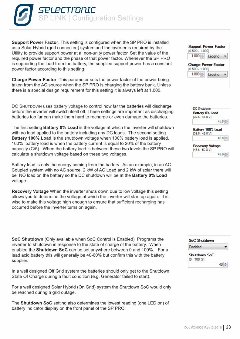
Support Power Factor. This setting is configured when the SP PRO is installed as a Solar Hybrid (grid connected) system and the inverter is required by the Utility to provide support power at a non-unity power factor. Set the value of the required power factor and the phase of that power factor. Whenever the SP PRO is supporting the load from the battery, the supplied support power has a constant power factor according to this setting
Charge Power Factor. This parameter sets the power factor of the power being taken from the AC source when the SP PRO is charging the battery bank. Unless there is a special design requirement for this setting it is always left at 1.000.
DC Shutdown uses battery voltage to control how far the batteries will discharge before the inverter will switch itself off. These settings are important as discharging batteries too far can make them hard to recharge or even damage the batteries.
The first setting Battery 0% Load is the voltage at which the inverter will shutdown with no load applied to the battery including any DC loads. The second setting Battery 100% Load is the shutdown voltage when 100% battery load is applied. 100% battery load is when the battery current is equal to 20% of the battery capacity (C/5). When the battery load is between these two levels the SP PRO will calculate a shutdown voltage based on these two voltages.
Battery load is only the energy coming from the battery. As an example, in an AC Coupled system with no AC source, 2 kW of AC Load and 2 kW of solar there will be NO load on the battery so the DC shutdown will be at the Battery 0% Load voltage .
Recovery Voltage When the inverter shuts down due to low voltage this setting allows you to determine the voltage at which the inverter will start up again. It is wise to make this voltage high enough to ensure that sufficient recharging has occurred before the inverter turns on again.
SoC Shutdown.(Only available when SoC Control is Enabled) Programs the inverter to shutdown in response to the state of charge of the battery. When enabled the Shutdown SoC can be set anywhere between 0 and 100%. For a lead acid battery this will generally be 40-60% but confirm this with the battery supplier.
In a well designed Off Grid system the batteries should only get to the Shutdown State Of Charge during a fault condition (e.g. Generator failed to start).
For a well designed Solar Hybrid (On Grid) system the Shutdown SoC would only be reached during a grid outage.
The Shutdown SoC setting also determines the lowest reading (one LED on) of battery indicator display on the front panel of the SP PRO.
SP LINK | Configuration Settings
24 | Doc #OI0005 Rev13 2016
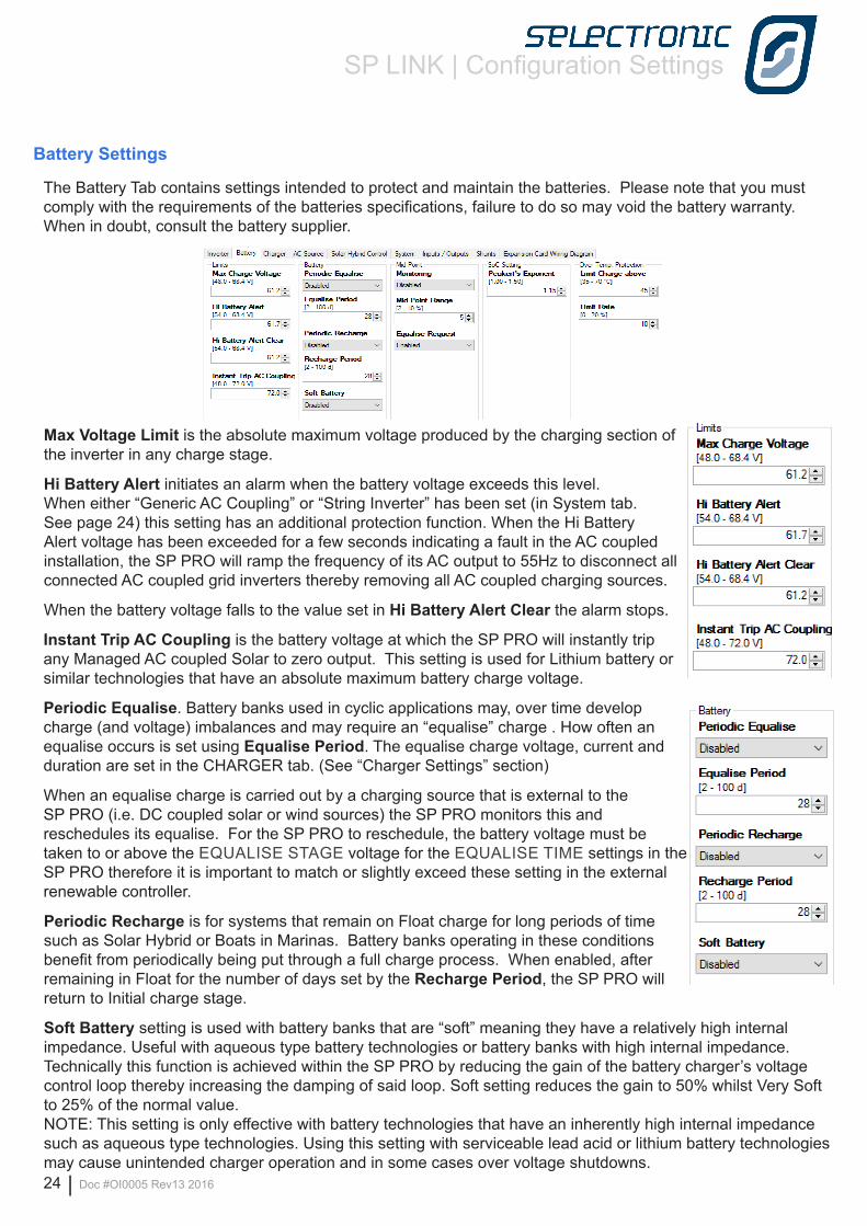
Max Voltage Limit is the absolute maximum voltage produced by the charging section of the inverter in any charge stage.
Hi Battery Alert initiates an alarm when the battery voltage exceeds this level. When either “Generic AC Coupling” or “String Inverter” has been set (in System tab. See page 24) this setting has an additional protection function. When the Hi Battery Alert voltage has been exceeded for a few seconds indicating a fault in the AC coupled installation, the SP PRO will ramp the frequency of its AC output to 55Hz to disconnect all connected AC coupled grid inverters thereby removing all AC coupled charging sources.
When the battery voltage falls to the value set in Hi Battery Alert Clear the alarm stops.
Instant Trip AC Coupling is the battery voltage at which the SP PRO will instantly trip any Managed AC coupled Solar to zero output. This setting is used for Lithium battery or similar technologies that have an absolute maximum battery charge voltage.
Periodic Equalise. Battery banks used in cyclic applications may, over time develop charge (and voltage) imbalances and may require an “equalise” charge . How often an equalise occurs is set using Equalise Period. The equalise charge voltage, current and duration are set in the CHARGER tab. (See “Charger Settings” section)
When an equalise charge is carried out by a charging source that is external to the SP PRO (i.e. DC coupled solar or wind sources) the SP PRO monitors this and reschedules its equalise. For the SP PRO to reschedule, the battery voltage must be taken to or above the EQUALISE STAGE voltage for the EQUALISE TIME settings in the SP PRO therefore it is important to match or slightly exceed these setting in the external renewable controller.
Periodic Recharge is for systems that remain on Float charge for long periods of time such as Solar Hybrid or Boats in Marinas. Battery banks operating in these conditions benefit from periodically being put through a full charge process. When enabled, after remaining in Float for the number of days set by the Recharge Period, the SP PRO will return to Initial charge stage.
Soft Battery setting is used with battery banks that are “soft” meaning they have a relatively high internal impedance. Useful with aqueous type battery technologies or battery banks with high internal impedance.Technically this function is achieved within the SP PRO by reducing the gain of the battery charger’s voltage control loop thereby increasing the damping of said loop. Soft setting reduces the gain to 50% whilst Very Soft to 25% of the normal value.NOTE: This setting is only effective with battery technologies that have an inherently high internal impedance such as aqueous type technologies. Using this setting with serviceable lead acid or lithium battery technologies may cause unintended charger operation and in some cases over voltage shutdowns.
Battery Settings
The Battery Tab contains settings intended to protect and maintain the batteries. Please note that you must comply with the requirements of the batteries specifications, failure to do so may void the battery warranty. When in doubt, consult the battery supplier.
SP LINK | Configuration Settings
Doc #OI0005 Rev13 2016 | 25
Charger Settings
This tab shows all the settings relating to the DC voltages and currents used in the battery recharge stages.
The normal charge cycle involves a four stage charge – Initial, Bulk, Absorption and Float– while periodically it is necessary to go one stage further, for the performance and longevity of the battery bank, to the Equalise stage. We will describe each of these stages as we progress. Please note there is a slider at the bottom of this page to move to more settings as this section is quite extensive.
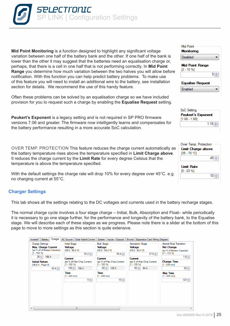
Mid Point Monitoring is a function designed to highlight any significant voltage variation between one half of the battery bank and the other. If one half of the bank is lower than the other it may suggest that the batteries need an equalisation charge or, perhaps, that there is a cell in one half that is not performing correctly. In Mid Point Range you determine how much variation between the two halves you will allow before notification. With this function you can help predict battery problems. To make use of this feature you will need to install an additional wire to the battery, see installation section for details. We recommend the use of this handy feature.
Often these problems can be solved by an equalisation charge so we have included provision for you to request such a charge by enabling the Equalise Request setting.
Peukert’s Exponent is a legacy setting and is not required in SP PRO firmware versions 7.06 and greater. The firmware now intelligently learns and compensates for the battery performance resulting in a more accurate SoC calculation.
OVER TEMP. PROTECTION This feature reduces the charge current automatically as the battery temperature rises above the temperature specified in Limit Charge above. It reduces the charge current by the Limit Rate for every degree Celsius that the temperature is above the temperature specified.
With the default settings the charge rate will drop 10% for every degree over 45°C. e.g. no charging current at 55°C.
SP LINK | Configuration Settings
26 | Doc #OI0005 Rev13 2016
The default charge settings should be considered as safe for most battery types. Exact charging parameters should be confirmed with the battery supplier.
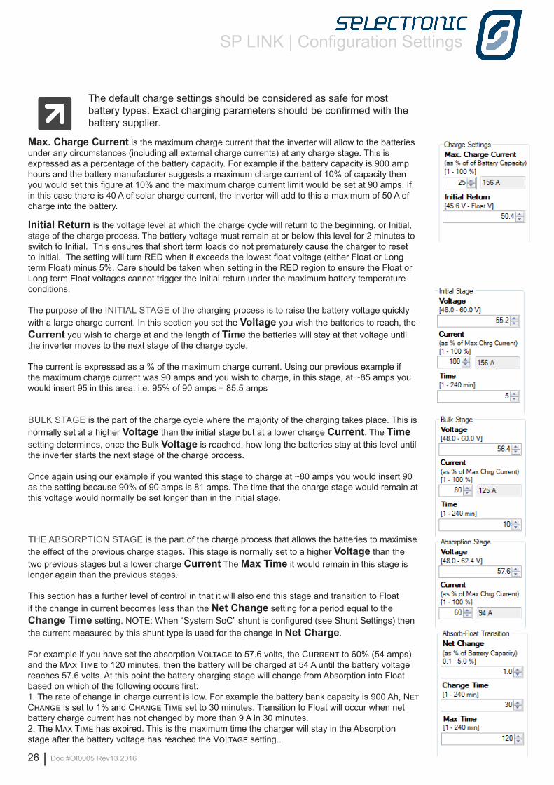
Max. Charge Current is the maximum charge current that the inverter will allow to the batteries under any circumstances (including all external charge currents) at any charge stage. This is expressed as a percentage of the battery capacity. For example if the battery capacity is 900 amp hours and the battery manufacturer suggests a maximum charge current of 10% of capacity then you would set this figure at 10% and the maximum charge current limit would be set at 90 amps. If, in this case there is 40 A of solar charge current, the inverter will add to this a maximum of 50 A of charge into the battery.
Initial Return is the voltage level at which the charge cycle will return to the beginning, or Initial, stage of the charge process. The battery voltage must remain at or below this level for 2 minutes to switch to Initial. This ensures that short term loads do not prematurely cause the charger to reset to Initial. The setting will turn RED when it exceeds the lowest float voltage (either Float or Long term Float) minus 5%. Care should be taken when setting in the RED region to ensure the Float or Long term Float voltages cannot trigger the Initial return under the maximum battery temperature conditions.
The purpose of the INITIAL STAGE of the charging process is to raise the battery voltage quickly with a large charge current. In this section you set the Voltage you wish the batteries to reach, the Current you wish to charge at and the length of Time the batteries will stay at that voltage until the inverter moves to the next stage of the charge cycle.
The current is expressed as a % of the maximum charge current. Using our previous example if the maximum charge current was 90 amps and you wish to charge, in this stage, at ~85 amps you would insert 95 in this area. i.e. 95% of 90 amps = 85.5 amps
BULK STAGE is the part of the charge cycle where the majority of the charging takes place. This is normally set at a higher Voltage than the initial stage but at a lower charge Current. The Time setting determines, once the Bulk Voltage is reached, how long the batteries stay at this level until the inverter starts the next stage of the charge process.
Once again using our example if you wanted this stage to charge at ~80 amps you would insert 90 as the setting because 90% of 90 amps is 81 amps. The time that the charge stage would remain at this voltage would normally be set longer than in the initial stage.
THE ABSORPTION STAGE is the part of the charge process that allows the batteries to maximise the effect of the previous charge stages. This stage is normally set to a higher Voltage than the two previous stages but a lower charge Current The Max Time it would remain in this stage is longer again than the previous stages.
This section has a further level of control in that it will also end this stage and transition to Float if the change in current becomes less than the Net Change setting for a period equal to the Change Time setting. NOTE: When “System SoC” shunt is configured (see Shunt Settings) then the current measured by this shunt type is used for the change in Net Charge.
For example if you have set the absorption Voltage to 57.6 volts, the Current to 60% (54 amps) and the Max Time to 120 minutes, then the battery will be charged at 54 A until the battery voltage reaches 57.6 volts. At this point the battery charging stage will change from Absorption into Float based on which of the following occurs first:1. The rate of change in charge current is low. For example the battery bank capacity is 900 Ah, Net Change is set to 1% and Change Time set to 30 minutes. Transition to Float will occur when net battery charge current has not changed by more than 9 A in 30 minutes.2. The Max Time has expired. This is the maximum time the charger will stay in the Absorption stage after the battery voltage has reached the Voltage setting..
SP LINK | Configuration Settings
Doc #OI0005 Rev13 2016 | 27
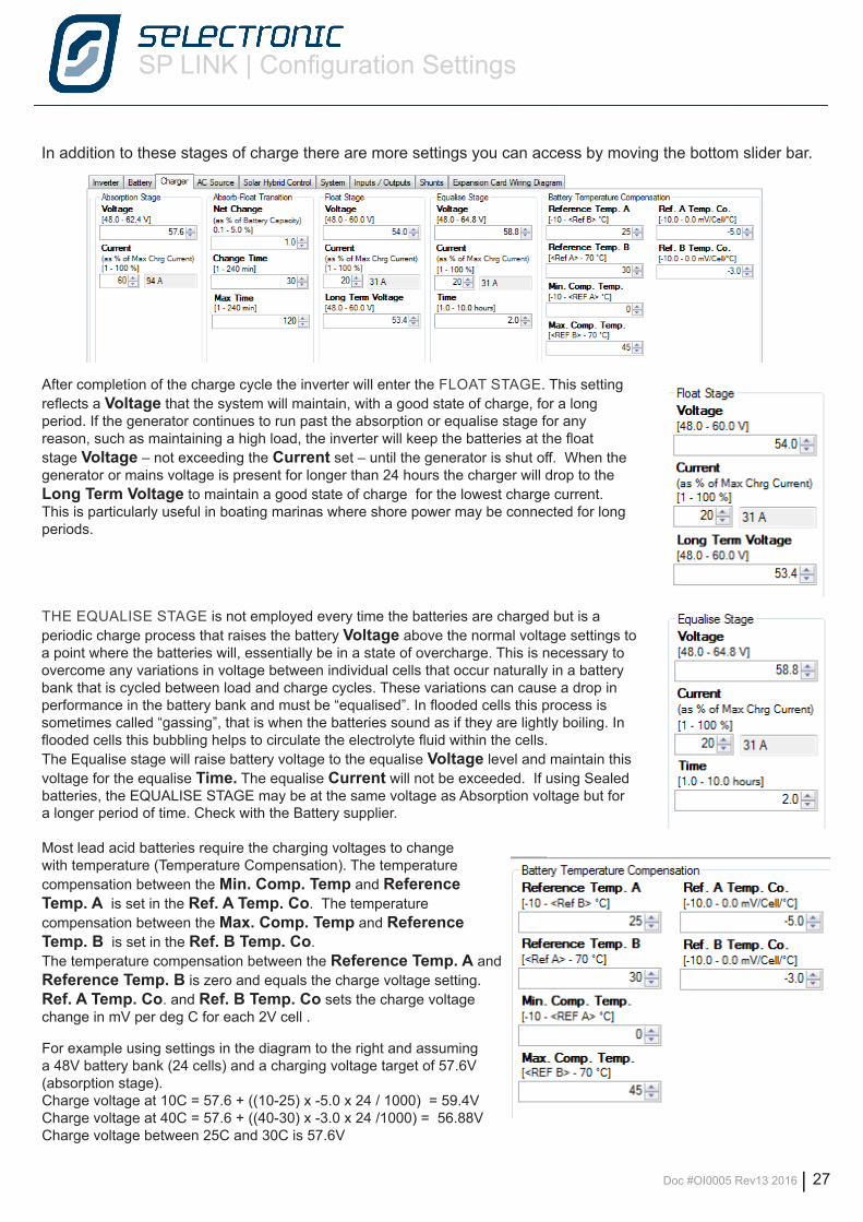
In addition to these stages of charge there are more settings you can access by moving the bottom slider bar.
After completion of the charge cycle the inverter will enter the FLOAT STAGE. This setting reflects a Voltage that the system will maintain, with a good state of charge, for a long period. If the generator continues to run past the absorption or equalise stage for any reason, such as maintaining a high load, the inverter will keep the batteries at the float stage Voltage – not exceeding the Current set – until the generator is shut off. When the generator or mains voltage is present for longer than 24 hours the charger will drop to the Long Term Voltage to maintain a good state of charge for the lowest charge current. This is particularly useful in boating marinas where shore power may be connected for long periods.
THE EQUALISE STAGE is not employed every time the batteries are charged but is a periodic charge process that raises the battery Voltage above the normal voltage settings to a point where the batteries will, essentially be in a state of overcharge. This is necessary to overcome any variations in voltage between individual cells that occur naturally in a battery bank that is cycled between load and charge cycles. These variations can cause a drop in performance in the battery bank and must be “equalised”. In flooded cells this process is sometimes called “gassing”, that is when the batteries sound as if they are lightly boiling. In flooded cells this bubbling helps to circulate the electrolyte fluid within the cells.The Equalise stage will raise battery voltage to the equalise Voltage level and maintain this voltage for the equalise Time. The equalise Current will not be exceeded. If using Sealed batteries, the EQUALISE STAGE may be at the same voltage as Absorption voltage but for a longer period of time. Check with the Battery supplier.
Most lead acid batteries require the charging voltages to change with temperature (Temperature Compensation). The temperature compensation between the Min. Comp. Temp and Reference Temp. A is set in the Ref. A Temp. Co. The temperature compensation between the Max. Comp. Temp and Reference Temp. B is set in the Ref. B Temp. Co. The temperature compensation between the Reference Temp. A and Reference Temp. B is zero and equals the charge voltage setting. Ref. A Temp. Co. and Ref. B Temp. Co sets the charge voltage change in mV per deg C for each 2V cell .
For example using settings in the diagram to the right and assuming a 48V battery bank (24 cells) and a charging voltage target of 57.6V (absorption stage). Charge voltage at 10C = 57.6 + ((10-25) x -5.0 x 24 / 1000) = 59.4VCharge voltage at 40C = 57.6 + ((40-30) x -3.0 x 24 /1000) = 56.88VCharge voltage between 25C and 30C is 57.6V
SP LINK | Configuration Settings
28 | Doc #OI0005 Rev13 2016
AC Source Settings
The next tab in our settings menu is the AC Source tab. In this section we are able to change important settings relating to either the generator or the mains voltage. We use the words AC Source rather than Generator, Grid or Shore power as the SP PRO can be used in a variety of applications which may include either of those AC supplies.
There are four sub-tabs within this section: • AC INPUT, relates to general settings that apply if either a generator or the mains grid are used as input power.• GENERATOR AUTO START relates to conditions that will start the generator automatically.• GENERATOR SCHEDULE START allows programming of scheduled run times for the system.• GENERATOR CONTROLLER SETTINGS is used to set up parameters that relate to the motor generator.
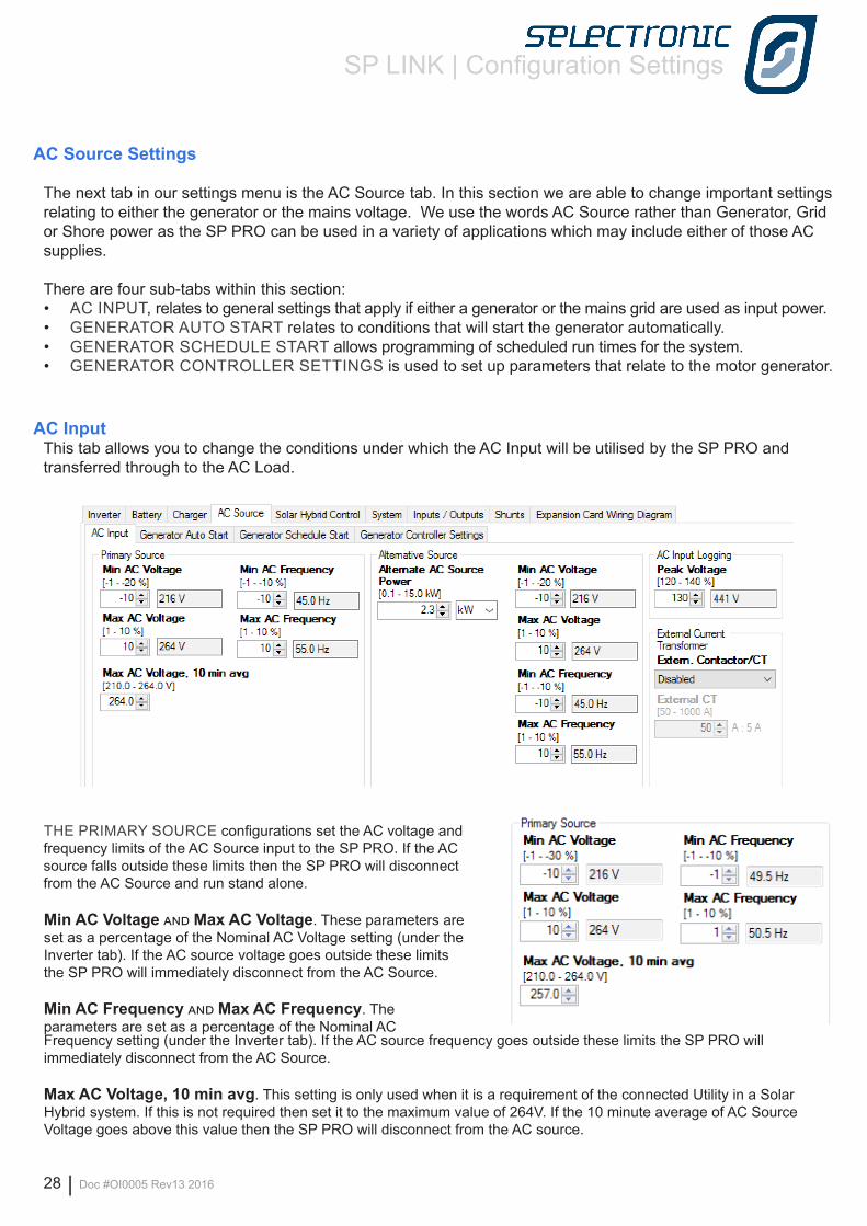
AC InputThis tab allows you to change the conditions under which the AC Input will be utilised by the SP PRO and transferred through to the AC Load.
Frequency setting (under the Inverter tab). If the AC source frequency goes outside these limits the SP PRO will immediately disconnect from the AC Source.
Max AC Voltage, 10 min avg. This setting is only used when it is a requirement of the connected Utility in a Solar Hybrid system. If this is not required then set it to the maximum value of 264V. If the 10 minute average of AC Source Voltage goes above this value then the SP PRO will disconnect from the AC source.
THE PRIMARY SOURCE configurations set the AC voltage and frequency limits of the AC Source input to the SP PRO. If the AC source falls outside these limits then the SP PRO will disconnect from the AC Source and run stand alone.
Min AC Voltage and Max AC Voltage. These parameters are set as a percentage of the Nominal AC Voltage setting (under the Inverter tab). If the AC source voltage goes outside these limits the SP PRO will immediately disconnect from the AC Source.
Min AC Frequency and Max AC Frequency. The parameters are set as a percentage of the Nominal AC
SP LINK | Configuration Settings
Doc #OI0005 Rev13 2016 | 29
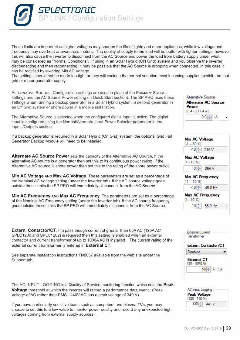
Alternative Source. Configuration settings are used in place of the Primary Source settings and the AC Source Power setting (in Quick Start section). The SP PRO uses these settings when running a backup generator in a Solar Hybrid system, a second generator in an Off Grid system or shore power in a mobile installation.
The Alternative Source is selected when the configured digital input is active. The digital input is configured using the Normal/Alternate Input Power Selector parameter in the Inputs/Outputs section.
If a backup generator is required in a Solar Hybrid (On Grid) system, the optional Grid Fail Generator Backup Module will need to be installed.
Alternate AC Source Power sets the capacity of the Alternative AC Source. If the alternative AC source is a generator then set this to its continuous power rating. If the Alternative AC source is shore power then set this to the rating of the shore power outlet.
Min AC Voltage and Max AC Voltage. These parameters are set as a percentage of the Nominal AC Voltage setting (under the Inverter tab). If the AC source voltage goes outside these limits the SP PRO will immediately disconnect from the AC Source.
Min AC Frequency and Max AC Frequency. The parameters are set as a percentage of the Nominal AC Frequency setting (under the Inverter tab). If the AC source frequency goes outside these limits the SP PRO will immediately disconnect from the AC Source.
Extern. Contactor/CT. If a pass though current of greater than 63A AC (125A AC SPLC1200 and SPLC1202) is required then this setting is enabled when an external contactor and current transformer of up to 1000A AC is installed. The current rating of the external current transformer is entered in External CT.
See separate Installation instructions TN0057 available from the web site under the Support tab.
The AC INPUT LOGGING is a Quality of Service monitoring function which sets the Peak Voltage threshold at which the inverter will record a performance data event. (Peak Voltage of AC rather than RMS - 240V AC has a peak voltage of 340 V)
If you have particularly sensitive loads such as computers and plasma TVs, you may choose to set this to a low value to monitor power quality and record any unexpected high voltages coming from external supply sources.
These limits are important as higher voltages may shorten the life of lights and other appliances; while low voltage and frequency may overheat or overstress motors. The quality of supply to the load will be better with tighter settings, however this will also cause the inverter to disconnect from the AC Source and power the load from battery supply under what may be considered as “Normal Conditions”. If using in an Solar Hybrid (ON Grid) system and you observe the inverter disconnecting and then reconnecting, it may be possible that the AC Source is drooping when connected, in this case it can be rectified by lowering Min AC Voltage.The settings should not be made too tight or they will exclude the normal variation most incoming supplies exhibit - be that grid or motor generator supply.
SP LINK | Configuration Settings
30 | Doc #OI0005 Rev13 2016
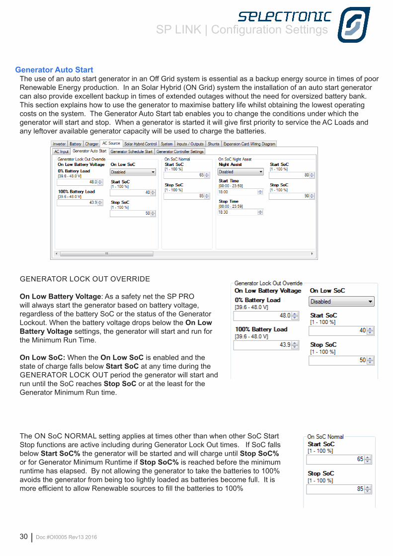
Generator Auto StartThe use of an auto start generator in an Off Grid system is essential as a backup energy source in times of poor Renewable Energy production. In an Solar Hybrid (ON Grid) system the installation of an auto start generator can also provide excellent backup in times of extended outages without the need for oversized battery bank. This section explains how to use the generator to maximise battery life whilst obtaining the lowest operating costs on the system. The Generator Auto Start tab enables you to change the conditions under which the generator will start and stop. When a generator is started it will give first priority to service the AC Loads and any leftover available generator capacity will be used to charge the batteries.
GENERATOR LOCK OUT OVERRIDE
On Low Battery Voltage: As a safety net the SP PRO will always start the generator based on battery voltage, regardless of the battery SoC or the status of the Generator Lockout. When the battery voltage drops below the On Low Battery Voltage settings, the generator will start and run for the Minimum Run Time.
On Low SoC: When the On Low SoC is enabled and the state of charge falls below Start SoC at any time during the GENERATOR LOCK OUT period the generator will start and run until the SoC reaches Stop SoC or at the least for the Generator Minimum Run time.
The ON SoC NORMAL setting applies at times other than when other SoC Start Stop functions are active including during Generator Lock Out times. If SoC falls below Start SoC% the generator will be started and will charge until Stop SoC% or for Generator Minimum Runtime if Stop SoC% is reached before the minimum runtime has elapsed. By not allowing the generator to take the batteries to 100% avoids the generator from being too lightly loaded as batteries become full. It is more efficient to allow Renewable sources to fill the batteries to 100%
SP LINK | Configuration Settings
Doc #OI0005 Rev13 2016 | 31
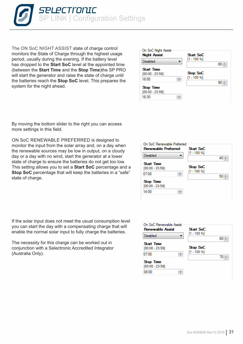
The ON SoC NIGHT ASSIST state of charge control monitors the State of Charge through the highest usage period, usually during the evening. If the battery level has dropped to the Start SoC level at the appointed time (between the Start Time and the Stop Time)the SP PRO will start the generator and raise the state of charge until the batteries reach the Stop SoC level. This prepares the system for the night ahead.
By moving the bottom slider to the right you can access more settings in this field.
ON SoC RENEWABLE PREFERRED is designed to monitor the input from the solar array and, on a day when the renewable sources may be low in output, on a cloudy day or a day with no wind, start the generator at a lower state of charge to ensure the batteries do not get too low. This setting allows you to set a Start SoC percentage and a Stop SoC percentage that will keep the batteries in a “safe” state of charge.
If the solar input does not meet the usual consumption level you can start the day with a compensating charge that will enable the normal solar input to fully charge the batteries.
The necessity for this charge can be worked out in conjunction with a Selectronic Accredited Integrator (Australia Only).
SP LINK | Configuration Settings
32 | Doc #OI0005 Rev13 2016
0
10
20
30
40
50
60
70
80
90
100
110
0:00 2:00 4:00 6:00 8:00 10:00 12:00 14:00 16:00 18:00 20:00 22:00
SoC
Lev
el
Time
On SoC Renewable Prefered
Generator Lock Out Override
On SoC Renewable Assist
On SoC Night Assist
SoC Gen Start
SoC Gen Stop
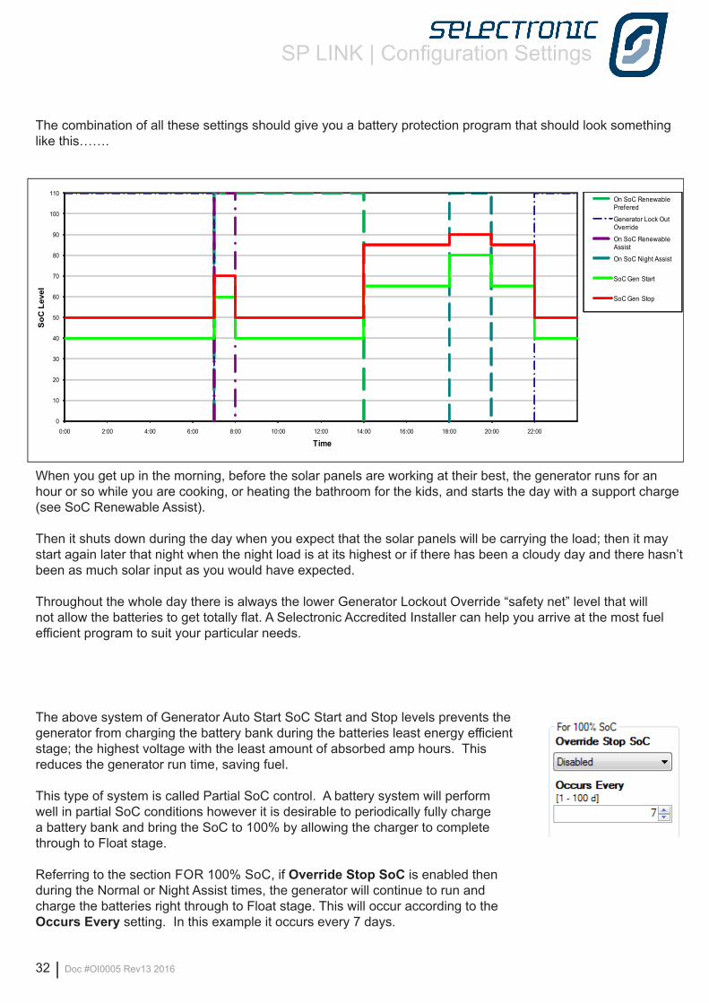
The combination of all these settings should give you a battery protection program that should look something like this…….
When you get up in the morning, before the solar panels are working at their best, the generator runs for an hour or so while you are cooking, or heating the bathroom for the kids, and starts the day with a support charge (see SoC Renewable Assist).
Then it shuts down during the day when you expect that the solar panels will be carrying the load; then it may start again later that night when the night load is at its highest or if there has been a cloudy day and there hasn’t been as much solar input as you would have expected.
Throughout the whole day there is always the lower Generator Lockout Override “safety net” level that will not allow the batteries to get totally flat. A Selectronic Accredited Installer can help you arrive at the most fuel efficient program to suit your particular needs.
The above system of Generator Auto Start SoC Start and Stop levels prevents the generator from charging the battery bank during the batteries least energy efficient stage; the highest voltage with the least amount of absorbed amp hours. This reduces the generator run time, saving fuel.
This type of system is called Partial SoC control. A battery system will perform well in partial SoC conditions however it is desirable to periodically fully charge a battery bank and bring the SoC to 100% by allowing the charger to complete through to Float stage.
Referring to the section FOR 100% SoC, if Override Stop SoC is enabled then during the Normal or Night Assist times, the generator will continue to run and charge the batteries right through to Float stage. This will occur according to the Occurs Every setting. In this example it occurs every 7 days.
SP LINK | Configuration Settings
Doc #OI0005 Rev13 2016 | 33
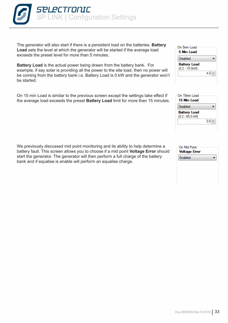
The generator will also start if there is a persistent load on the batteries. Battery Load sets the level at which the generator will be started if the average load exceeds the preset level for more than 5 minutes.
Battery Load is the actual power being drawn from the battery bank. For example, if say solar is providing all the power to the site load, then no power will be coming from the battery bank i.e. Battery Load is 0 kW and the generator won’t be started.
On 15 min Load is similar to the previous screen except the settings take effect if the average load exceeds the preset Battery Load limit for more than 15 minutes.
We previously discussed mid point monitoring and its ability to help determine a battery fault. This screen allows you to choose if a mid point Voltage Error should start the generator. The generator will then perform a full charge of the battery bank and if equalise is enable will perform an equalise charge.
SP LINK | Configuration Settings
34 | Doc #OI0005 Rev13 2016
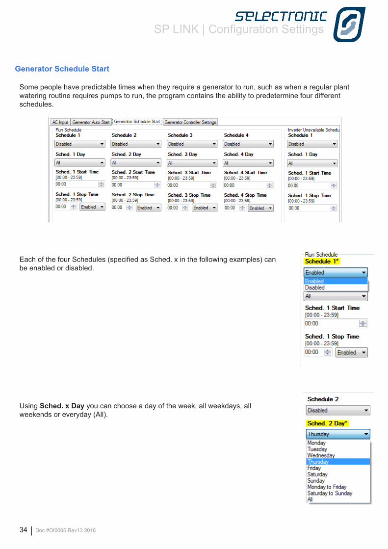
Generator Schedule Start
Some people have predictable times when they require a generator to run, such as when a regular plant watering routine requires pumps to run, the program contains the ability to predetermine four different schedules.
Each of the four Schedules (specified as Sched. x in the following examples) can be enabled or disabled.
Using Sched. x Day you can choose a day of the week, all weekdays, all weekends or everyday (All).
SP LINK | Configuration Settings
Doc #OI0005 Rev13 2016 | 35
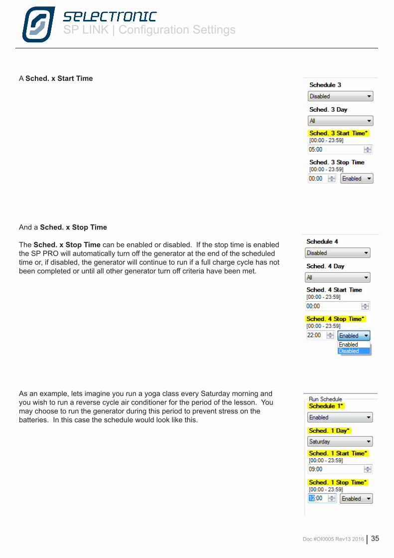
A Sched. x Start Time
And a Sched. x Stop Time
The Sched. x Stop Time can be enabled or disabled. If the stop time is enabled the SP PRO will automatically turn off the generator at the end of the scheduled time or, if disabled, the generator will continue to run if a full charge cycle has not been completed or until all other generator turn off criteria have been met.
As an example, lets imagine you run a yoga class every Saturday morning and you wish to run a reverse cycle air conditioner for the period of the lesson. You may choose to run the generator during this period to prevent stress on the batteries. In this case the schedule would look like this.
SP LINK | Configuration Settings
36 | Doc #OI0005 Rev13 2016
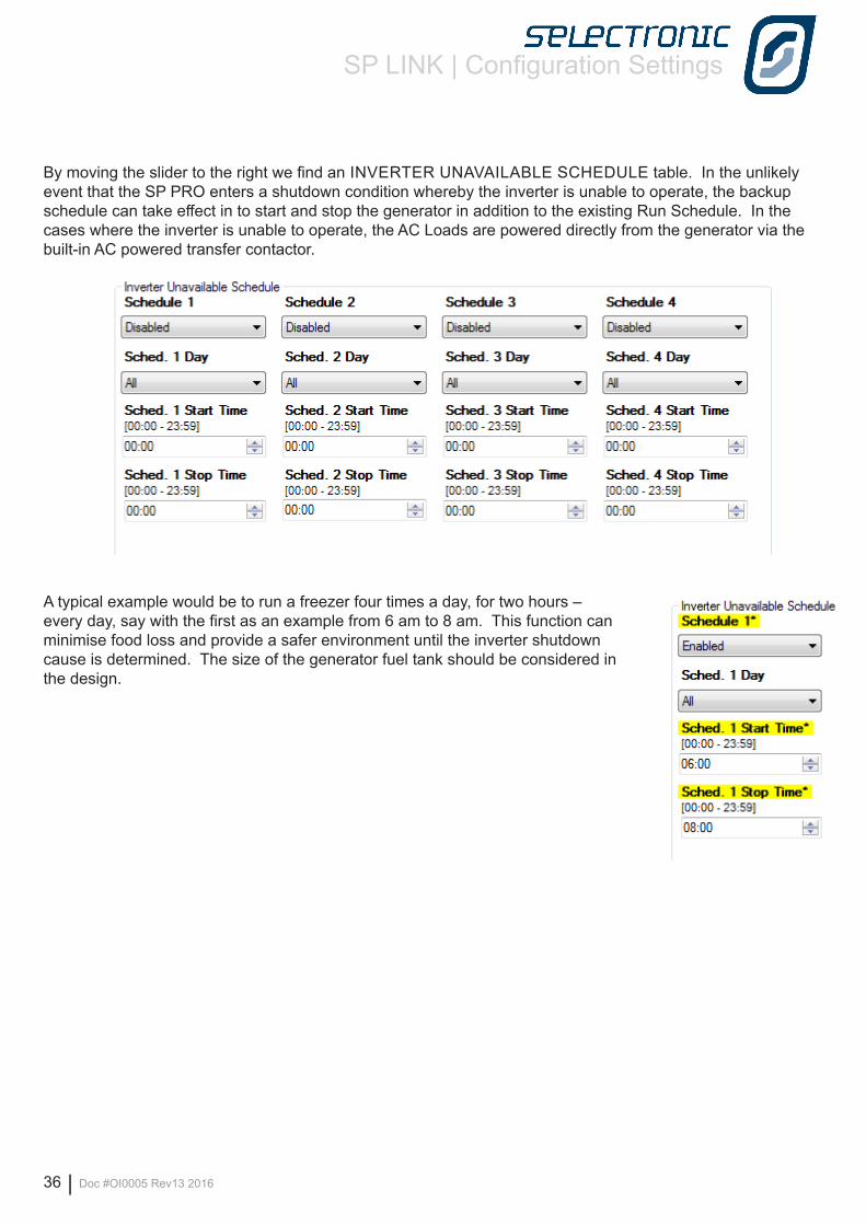
By moving the slider to the right we find an INVERTER UNAVAILABLE SCHEDULE table. In the unlikely event that the SP PRO enters a shutdown condition whereby the inverter is unable to operate, the backup schedule can take effect in to start and stop the generator in addition to the existing Run Schedule. In the cases where the inverter is unable to operate, the AC Loads are powered directly from the generator via the built-in AC powered transfer contactor.
A typical example would be to run a freezer four times a day, for two hours – every day, say with the first as an example from 6 am to 8 am. This function can minimise food loss and provide a safer environment until the inverter shutdown cause is determined. The size of the generator fuel tank should be considered in the design.
SP LINK | Configuration Settings
Doc #OI0005 Rev13 2016 | 37
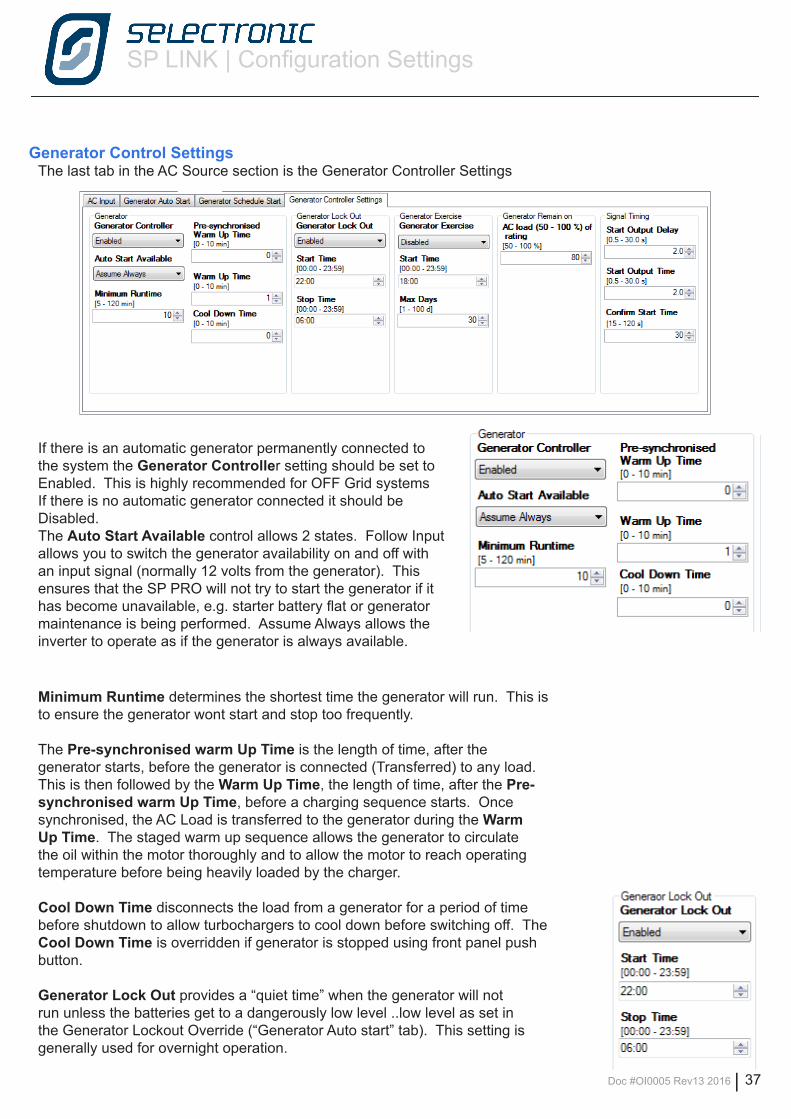
If there is an automatic generator permanently connected to the system the Generator Controller setting should be set to Enabled. This is highly recommended for OFF Grid systems If there is no automatic generator connected it should be Disabled.The Auto Start Available control allows 2 states. Follow Input allows you to switch the generator availability on and off with an input signal (normally 12 volts from the generator). This ensures that the SP PRO will not try to start the generator if it has become unavailable, e.g. starter battery flat or generator maintenance is being performed. Assume Always allows the inverter to operate as if the generator is always available.
Minimum Runtime determines the shortest time the generator will run. This is to ensure the generator wont start and stop too frequently.
The Pre-synchronised warm Up Time is the length of time, after the generator starts, before the generator is connected (Transferred) to any load.This is then followed by the Warm Up Time, the length of time, after the Pre-synchronised warm Up Time, before a charging sequence starts. Once synchronised, the AC Load is transferred to the generator during the Warm Up Time. The staged warm up sequence allows the generator to circulate the oil within the motor thoroughly and to allow the motor to reach operating temperature before being heavily loaded by the charger.
Cool Down Time disconnects the load from a generator for a period of time before shutdown to allow turbochargers to cool down before switching off. The Cool Down Time is overridden if generator is stopped using front panel push button.
Generator Lock Out provides a “quiet time” when the generator will not run unless the batteries get to a dangerously low level ..low level as set in the Generator Lockout Override (“Generator Auto start” tab). This setting is generally used for overnight operation.
Generator Control SettingsThe last tab in the AC Source section is the Generator Controller Settings
SP LINK | Configuration Settings
38 | Doc #OI0005 Rev13 2016
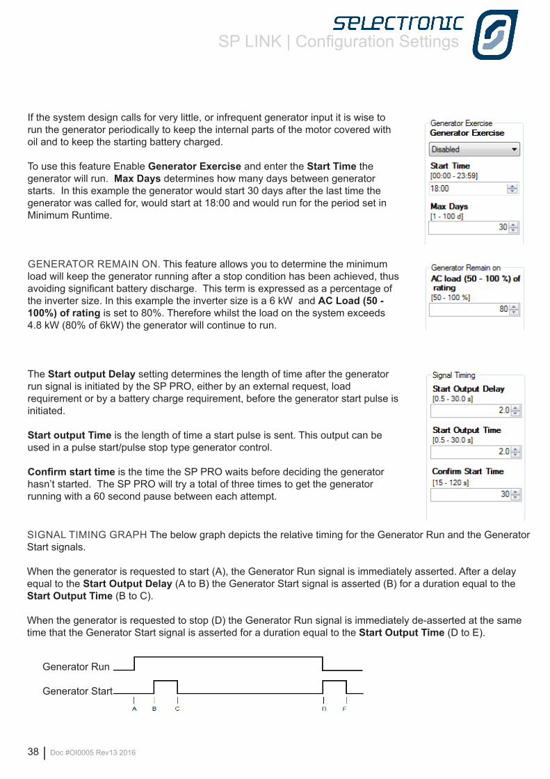
If the system design calls for very little, or infrequent generator input it is wise to run the generator periodically to keep the internal parts of the motor covered with oil and to keep the starting battery charged.
To use this feature Enable Generator Exercise and enter the Start Time the generator will run. Max Days determines how many days between generator starts. In this example the generator would start 30 days after the last time the generator was called for, would start at 18:00 and would run for the period set in Minimum Runtime.
GENERATOR REMAIN ON. This feature allows you to determine the minimum load will keep the generator running after a stop condition has been achieved, thus avoiding significant battery discharge. This term is expressed as a percentage of the inverter size. In this example the inverter size is a 6 kW and AC Load (50 - 100%) of rating is set to 80%. Therefore whilst the load on the system exceeds 4.8 kW (80% of 6kW) the generator will continue to run.
The Start output Delay setting determines the length of time after the generator run signal is initiated by the SP PRO, either by an external request, load requirement or by a battery charge requirement, before the generator start pulse is initiated.
Start output Time is the length of time a start pulse is sent. This output can be used in a pulse start/pulse stop type generator control.
Confirm start time is the time the SP PRO waits before deciding the generator hasn’t started. The SP PRO will try a total of three times to get the generator running with a 60 second pause between each attempt.
SIGNAL TIMING GRAPH The below graph depicts the relative timing for the Generator Run and the Generator Start signals.
When the generator is requested to start (A), the Generator Run signal is immediately asserted. After a delay equal to the Start Output Delay (A to B) the Generator Start signal is asserted (B) for a duration equal to the Start Output Time (B to C).
When the generator is requested to stop (D) the Generator Run signal is immediately de-asserted at the same time that the Generator Start signal is asserted for a duration equal to the Start Output Time (D to E).
Generator Run
Generator Start
SP LINK | Configuration Settings
Doc #OI0005 Rev13 2016 | 39
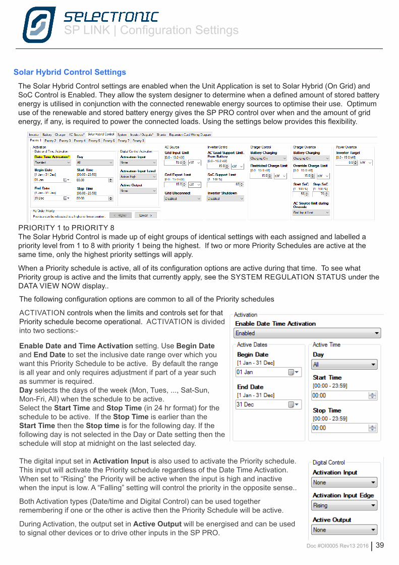
Solar Hybrid Control SettingsThe Solar Hybrid Control settings are enabled when the Unit Application is set to Solar Hybrid (On Grid) and SoC Control is Enabled. They allow the system designer to determine when a defined amount of stored battery energy is utilised in conjunction with the connected renewable energy sources to optimise their use. Optimum use of the renewable and stored battery energy gives the SP PRO control over when and the amount of grid energy, if any, is required to power the connected loads. Using the settings below provides this flexibility.
PRIORITY 1 to PRIORITY 8The Solar Hybrid Control is made up of eight groups of identical settings with each assigned and labelled a priority level from 1 to 8 with priority 1 being the highest. If two or more Priority Schedules are active at the same time, only the highest priority settings will apply.
When a Priority schedule is active, all of its configuration options are active during that time. To see what Priority group is active and the limits that currently apply, see the SYSTEM REGULATION STATUS under the DATA VIEW NOW display..
The following configuration options are common to all of the Priority schedules
ACTIVATION controls when the limits and controls set for that Priority schedule become operational. ACTIVATION is divided into two sections:-
Enable Date and Time Activation setting. Use Begin Date and End Date to set the inclusive date range over which you want this Priority Schedule to be active. By default the range is all year and only requires adjustment if part of a year such as summer is required.Day selects the days of the week (Mon, Tues, ..., Sat-Sun, Mon-Fri, All) when the schedule to be active.Select the Start Time and Stop Time (in 24 hr format) for the schedule to be active. If the Stop Time is earlier than the Start Time then the Stop time is for the following day. If the following day is not selected in the Day or Date setting then the schedule will stop at midnight on the last selected day.
The digital input set in Activation Input is also used to activate the Priority schedule. This input will activate the Priority schedule regardless of the Date Time Activation. When set to “Rising” the Priority will be active when the input is high and inactive when the input is low. A “Falling” setting will control the priority in the opposite sense..
Both Activation types (Date/time and Digital Control) can be used together remembering if one or the other is active then the Priority Schedule will be active.
During Activation, the output set in Active Output will be energised and can be used to signal other devices or to drive other inputs in the SP PRO.
SP LINK | Configuration Settings
40 | Doc #OI0005 Rev13 2016
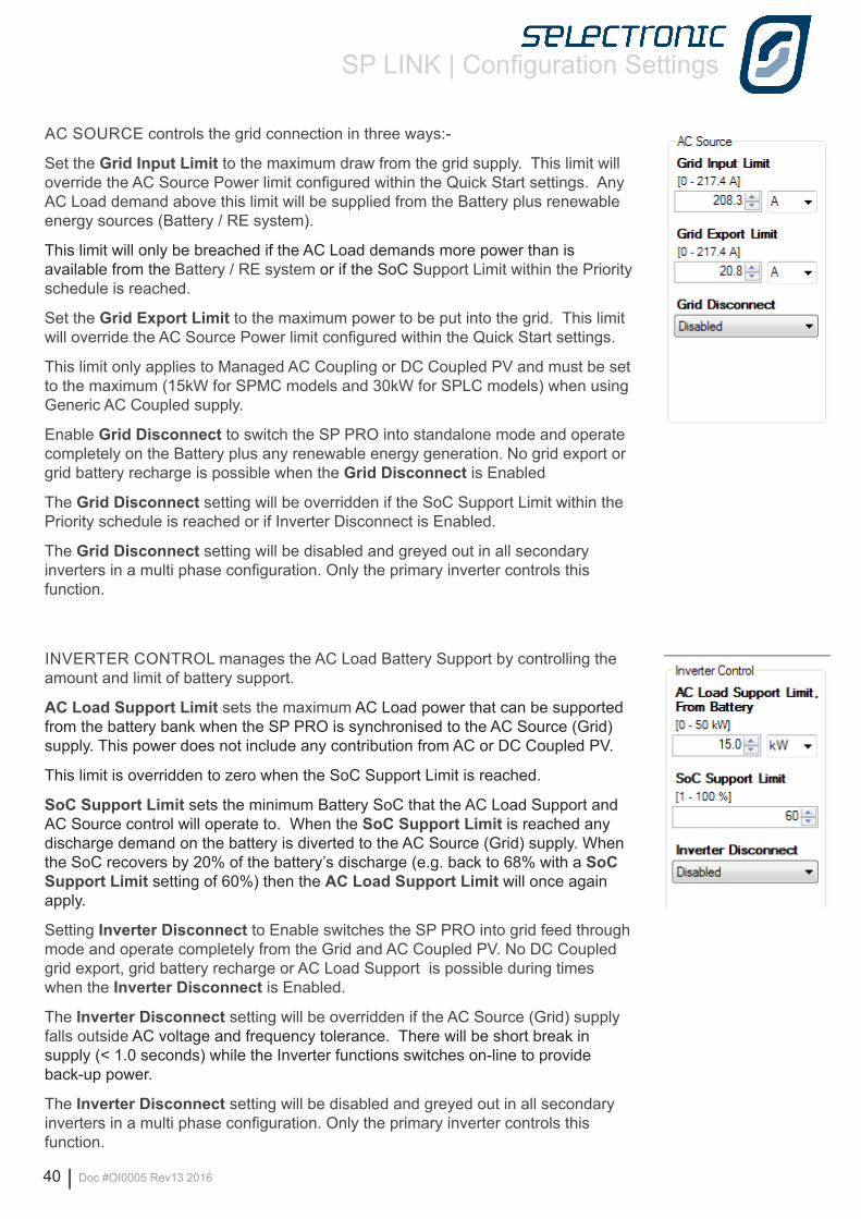
AC SOURCE controls the grid connection in three ways:-
Set the Grid Input Limit to the maximum draw from the grid supply. This limit will override the AC Source Power limit configured within the Quick Start settings. Any AC Load demand above this limit will be supplied from the Battery plus renewable energy sources (Battery / RE system).
This limit will only be breached if the AC Load demands more power than is available from the Battery / RE system or if the SoC Support Limit within the Priority schedule is reached.
Set the Grid Export Limit to the maximum power to be put into the grid. This limit will override the AC Source Power limit configured within the Quick Start settings.
This limit only applies to Managed AC Coupling or DC Coupled PV and must be set to the maximum (15kW for SPMC models and 30kW for SPLC models) when using Generic AC Coupled supply.
Enable Grid Disconnect to switch the SP PRO into standalone mode and operate completely on the Battery plus any renewable energy generation. No grid export or grid battery recharge is possible when the Grid Disconnect is Enabled
The Grid Disconnect setting will be overridden if the SoC Support Limit within the Priority schedule is reached or if Inverter Disconnect is Enabled.
The Grid Disconnect setting will be disabled and greyed out in all secondary inverters in a multi phase configuration. Only the primary inverter controls this function.
INVERTER CONTROL manages the AC Load Battery Support by controlling the amount and limit of battery support.
AC Load Support Limit sets the maximum AC Load power that can be supported from the battery bank when the SP PRO is synchronised to the AC Source (Grid) supply. This power does not include any contribution from AC or DC Coupled PV.
This limit is overridden to zero when the SoC Support Limit is reached.
SoC Support Limit sets the minimum Battery SoC that the AC Load Support and AC Source control will operate to. When the SoC Support Limit is reached any discharge demand on the battery is diverted to the AC Source (Grid) supply. When the SoC recovers by 20% of the battery’s discharge (e.g. back to 68% with a SoC Support Limit setting of 60%) then the AC Load Support Limit will once again apply.
Setting Inverter Disconnect to Enable switches the SP PRO into grid feed through mode and operate completely from the Grid and AC Coupled PV. No DC Coupled grid export, grid battery recharge or AC Load Support is possible during times when the Inverter Disconnect is Enabled.
The Inverter Disconnect setting will be overridden if the AC Source (Grid) supply falls outside AC voltage and frequency tolerance. There will be short break in supply (< 1.0 seconds) while the Inverter functions switches on-line to provide back-up power.
The Inverter Disconnect setting will be disabled and greyed out in all secondary inverters in a multi phase configuration. Only the primary inverter controls this function.
SP LINK | Configuration Settings
Doc #OI0005 Rev13 2016 | 41
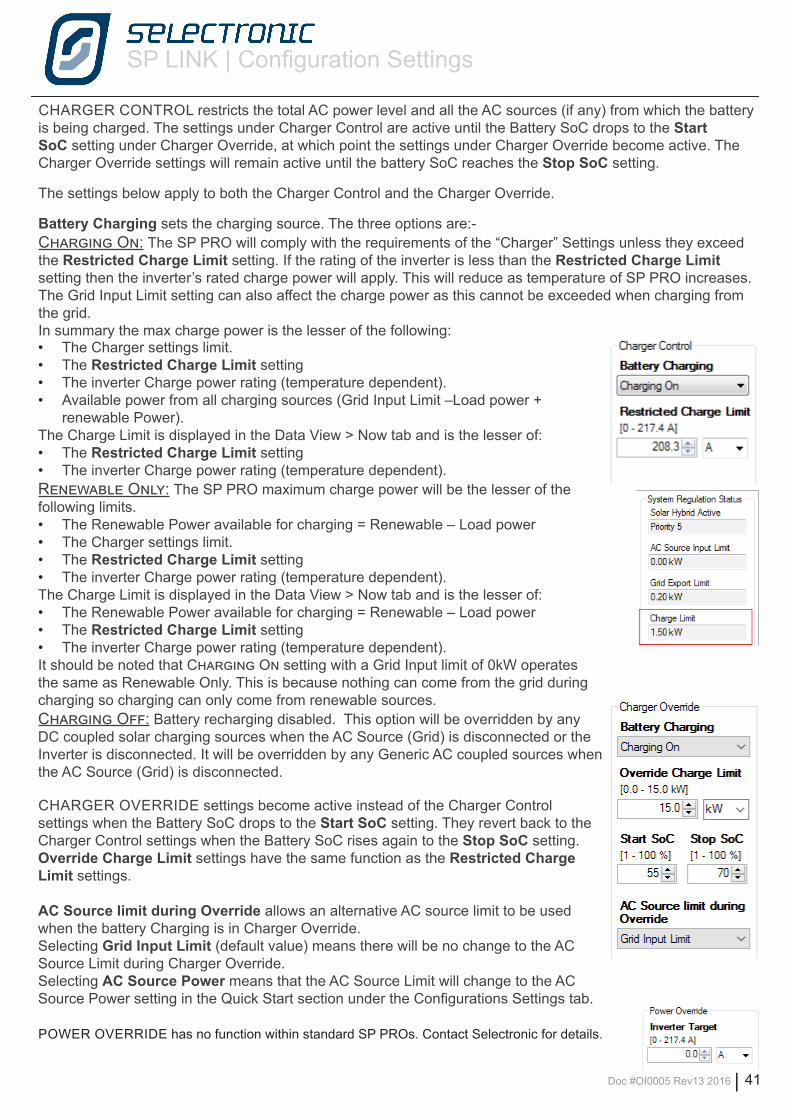
CHARGER CONTROL restricts the total AC power level and all the AC sources (if any) from which the battery is being charged. The settings under Charger Control are active until the Battery SoC drops to the Start SoC setting under Charger Override, at which point the settings under Charger Override become active. The Charger Override settings will remain active until the battery SoC reaches the Stop SoC setting.
The settings below apply to both the Charger Control and the Charger Override.
Battery Charging sets the charging source. The three options are:-Charging On: The SP PRO will comply with the requirements of the “Charger” Settings unless they exceed the Restricted Charge Limit setting. If the rating of the inverter is less than the Restricted Charge Limit setting then the inverter’s rated charge power will apply. This will reduce as temperature of SP PRO increases. The Grid Input Limit setting can also affect the charge power as this cannot be exceeded when charging from the grid. In summary the max charge power is the lesser of the following:• The Charger settings limit.• The Restricted Charge Limit setting• The inverter Charge power rating (temperature dependent).• Available power from all charging sources (Grid Input Limit –Load power +
renewable Power).The Charge Limit is displayed in the Data View > Now tab and is the lesser of:• The Restricted Charge Limit setting• The inverter Charge power rating (temperature dependent).Renewable Only: The SP PRO maximum charge power will be the lesser of the following limits. • The Renewable Power available for charging = Renewable – Load power• The Charger settings limit.• The Restricted Charge Limit setting• The inverter Charge power rating (temperature dependent).The Charge Limit is displayed in the Data View > Now tab and is the lesser of:• The Renewable Power available for charging = Renewable – Load power• The Restricted Charge Limit setting• The inverter Charge power rating (temperature dependent).It should be noted that Charging On setting with a Grid Input limit of 0kW operates the same as Renewable Only. This is because nothing can come from the grid during charging so charging can only come from renewable sources.Charging Off: Battery recharging disabled. This option will be overridden by any DC coupled solar charging sources when the AC Source (Grid) is disconnected or the Inverter is disconnected. It will be overridden by any Generic AC coupled sources when the AC Source (Grid) is disconnected.
CHARGER OVERRIDE settings become active instead of the Charger Control settings when the Battery SoC drops to the Start SoC setting. They revert back to the Charger Control settings when the Battery SoC rises again to the Stop SoC setting. Override Charge Limit settings have the same function as the Restricted Charge Limit settings.
AC Source limit during Override allows an alternative AC source limit to be used when the battery Charging is in Charger Override. Selecting Grid Input Limit (default value) means there will be no change to the AC Source Limit during Charger Override.Selecting AC Source Power means that the AC Source Limit will change to the AC Source Power setting in the Quick Start section under the Configurations Settings tab.
POWER OVERRIDE has no function within standard SP PROs. Contact Selectronic for details.
SP LINK | Configuration Settings
42 | Doc #OI0005 Rev13 2016
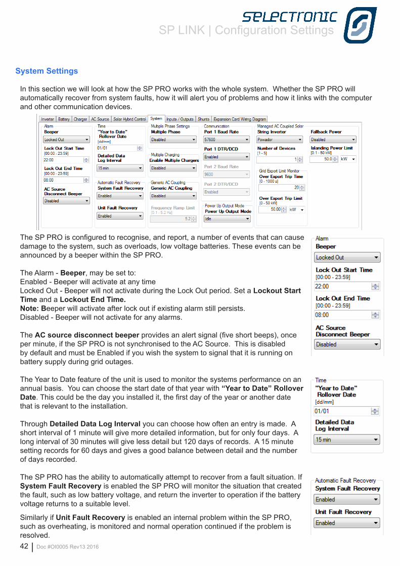
System Settings
In this section we will look at how the SP PRO works with the whole system. Whether the SP PRO will automatically recover from system faults, how it will alert you of problems and how it links with the computer and other communication devices.
The SP PRO is configured to recognise, and report, a number of events that can cause damage to the system, such as overloads, low voltage batteries. These events can be announced by a beeper within the SP PRO.
The Alarm - Beeper, may be set to:Enabled - Beeper will activate at any timeLocked Out - Beeper will not activate during the Lock Out period. Set a Lockout Start Time and a Lockout End Time. Note: Beeper will activate after lock out if existing alarm still persists.Disabled - Beeper will not activate for any alarms.
The AC source disconnect beeper provides an alert signal (five short beeps), once per minute, if the SP PRO is not synchronised to the AC Source. This is disabled by default and must be Enabled if you wish the system to signal that it is running on battery supply during grid outages.
The Year to Date feature of the unit is used to monitor the systems performance on an annual basis. You can choose the start date of that year with “Year to Date” Rollover Date. This could be the day you installed it, the first day of the year or another date that is relevant to the installation.
Through Detailed Data Log Interval you can choose how often an entry is made. A short interval of 1 minute will give more detailed information, but for only four days. A long interval of 30 minutes will give less detail but 120 days of records. A 15 minute setting records for 60 days and gives a good balance between detail and the number of days recorded.
The SP PRO has the ability to automatically attempt to recover from a fault situation. If System Fault Recovery is enabled the SP PRO will monitor the situation that created the fault, such as low battery voltage, and return the inverter to operation if the battery voltage returns to a suitable level.
Similarly if Unit Fault Recovery is enabled an internal problem within the SP PRO, such as overheating, is monitored and normal operation continued if the problem is resolved.
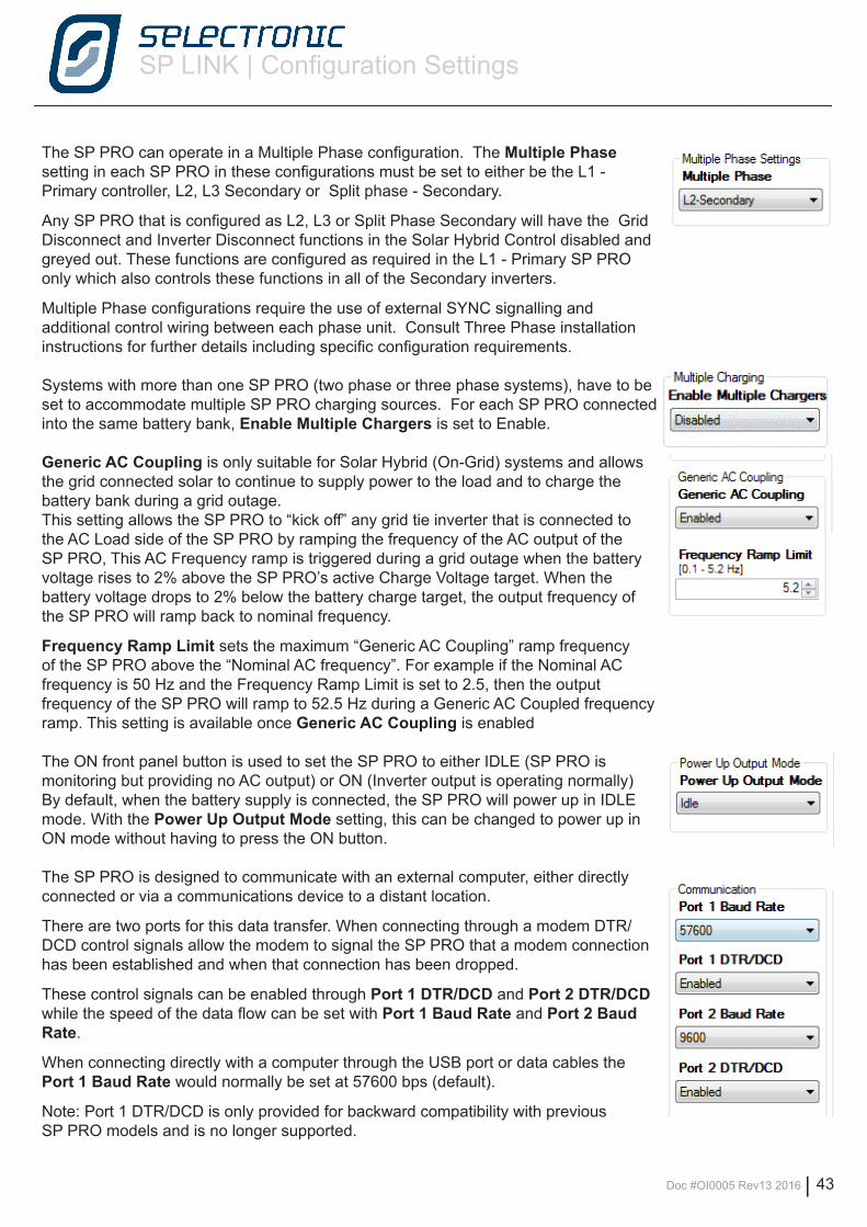
SP LINK | Configuration Settings
Doc #OI0005 Rev13 2016 | 43
The SP PRO can operate in a Multiple Phase configuration. The Multiple Phase setting in each SP PRO in these configurations must be set to either be the L1 - Primary controller, L2, L3 Secondary or Split phase - Secondary.
Any SP PRO that is configured as L2, L3 or Split Phase Secondary will have the Grid Disconnect and Inverter Disconnect functions in the Solar Hybrid Control disabled and greyed out. These functions are configured as required in the L1 - Primary SP PRO only which also controls these functions in all of the Secondary inverters.
Multiple Phase configurations require the use of external SYNC signalling and additional control wiring between each phase unit. Consult Three Phase installation instructions for further details including specific configuration requirements.
Systems with more than one SP PRO (two phase or three phase systems), have to be set to accommodate multiple SP PRO charging sources. For each SP PRO connected into the same battery bank, Enable Multiple Chargers is set to Enable.
Generic AC Coupling is only suitable for Solar Hybrid (On-Grid) systems and allows the grid connected solar to continue to supply power to the load and to charge the battery bank during a grid outage.This setting allows the SP PRO to “kick off” any grid tie inverter that is connected to the AC Load side of the SP PRO by ramping the frequency of the AC output of the SP PRO, This AC Frequency ramp is triggered during a grid outage when the battery voltage rises to 2% above the SP PRO’s active Charge Voltage target. When the battery voltage drops to 2% below the battery charge target, the output frequency of the SP PRO will ramp back to nominal frequency.
Frequency Ramp Limit sets the maximum “Generic AC Coupling” ramp frequency of the SP PRO above the “Nominal AC frequency”. For example if the Nominal AC frequency is 50 Hz and the Frequency Ramp Limit is set to 2.5, then the output frequency of the SP PRO will ramp to 52.5 Hz during a Generic AC Coupled frequency ramp. This setting is available once Generic AC Coupling is enabled
The ON front panel button is used to set the SP PRO to either IDLE (SP PRO is monitoring but providing no AC output) or ON (Inverter output is operating normally) By default, when the battery supply is connected, the SP PRO will power up in IDLE mode. With the Power Up Output Mode setting, this can be changed to power up in ON mode without having to press the ON button.
The SP PRO is designed to communicate with an external computer, either directly connected or via a communications device to a distant location.
There are two ports for this data transfer. When connecting through a modem DTR/DCD control signals allow the modem to signal the SP PRO that a modem connection has been established and when that connection has been dropped.
These control signals can be enabled through Port 1 DTR/DCD and Port 2 DTR/DCD while the speed of the data flow can be set with Port 1 Baud Rate and Port 2 Baud Rate.
When connecting directly with a computer through the USB port or data cables the Port 1 Baud Rate would normally be set at 57600 bps (default).
Note: Port 1 DTR/DCD is only provided for backward compatibility with previous SP PRO models and is no longer supported.
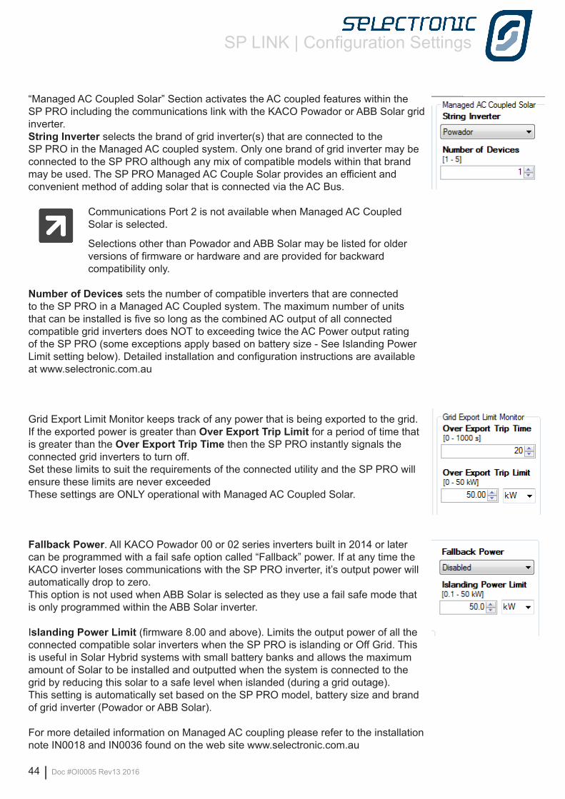
SP LINK | Configuration Settings
44 | Doc #OI0005 Rev13 2016
“Managed AC Coupled Solar” Section activates the AC coupled features within the SP PRO including the communications link with the KACO Powador or ABB Solar grid inverter. String Inverter selects the brand of grid inverter(s) that are connected to the SP PRO in the Managed AC coupled system. Only one brand of grid inverter may be connected to the SP PRO although any mix of compatible models within that brand may be used. The SP PRO Managed AC Couple Solar provides an efficient and convenient method of adding solar that is connected via the AC Bus.
Communications Port 2 is not available when Managed AC Coupled Solar is selected.
Selections other than Powador and ABB Solar may be listed for older versions of firmware or hardware and are provided for backward compatibility only.
Number of Devices sets the number of compatible inverters that are connected to the SP PRO in a Managed AC Coupled system. The maximum number of units that can be installed is five so long as the combined AC output of all connected compatible grid inverters does NOT to exceeding twice the AC Power output rating of the SP PRO (some exceptions apply based on battery size - See Islanding Power Limit setting below). Detailed installation and configuration instructions are available at www.selectronic.com.au
Grid Export Limit Monitor keeps track of any power that is being exported to the grid. If the exported power is greater than Over Export Trip Limit for a period of time that is greater than the Over Export Trip Time then the SP PRO instantly signals the connected grid inverters to turn off. Set these limits to suit the requirements of the connected utility and the SP PRO will ensure these limits are never exceededThese settings are ONLY operational with Managed AC Coupled Solar.
Fallback Power. All KACO Powador 00 or 02 series inverters built in 2014 or later can be programmed with a fail safe option called “Fallback” power. If at any time the KACO inverter loses communications with the SP PRO inverter, it’s output power will automatically drop to zero. This option is not used when ABB Solar is selected as they use a fail safe mode that is only programmed within the ABB Solar inverter.
Islanding Power Limit (firmware 8.00 and above). Limits the output power of all the connected compatible solar inverters when the SP PRO is islanding or Off Grid. This is useful in Solar Hybrid systems with small battery banks and allows the maximum amount of Solar to be installed and outputted when the system is connected to the grid by reducing this solar to a safe level when islanded (during a grid outage).This setting is automatically set based on the SP PRO model, battery size and brand of grid inverter (Powador or ABB Solar).
For more detailed information on Managed AC coupling please refer to the installation note IN0018 and IN0036 found on the web site www.selectronic.com.au
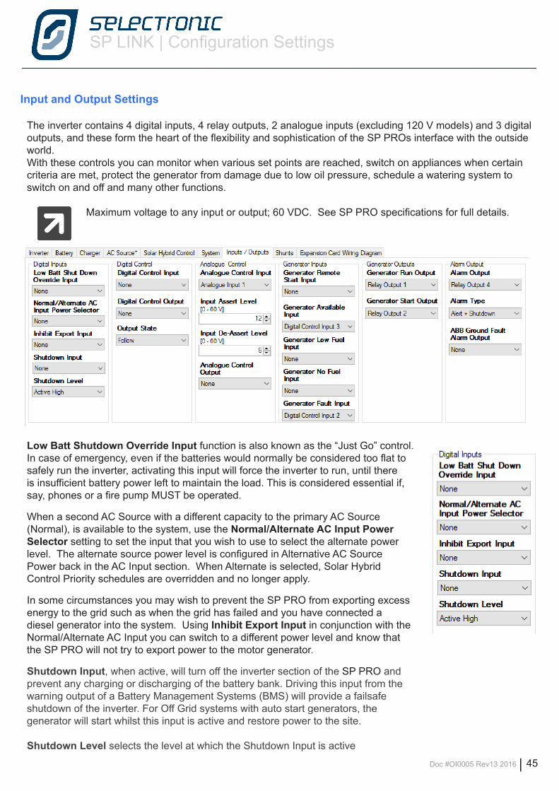
SP LINK | Configuration Settings
Doc #OI0005 Rev13 2016 | 45
Input and Output Settings
The inverter contains 4 digital inputs, 4 relay outputs, 2 analogue inputs (excluding 120 V models) and 3 digital outputs, and these form the heart of the flexibility and sophistication of the SP PROs interface with the outside world.With these controls you can monitor when various set points are reached, switch on appliances when certain criteria are met, protect the generator from damage due to low oil pressure, schedule a watering system to switch on and off and many other functions.
Maximum voltage to any input or output; 60 VDC. See SP PRO specifications for full details.
Low Batt Shutdown Override Input function is also known as the “Just Go” control. In case of emergency, even if the batteries would normally be considered too flat to safely run the inverter, activating this input will force the inverter to run, until there is insufficient battery power left to maintain the load. This is considered essential if, say, phones or a fire pump MUST be operated.
When a second AC Source with a different capacity to the primary AC Source (Normal), is available to the system, use the Normal/Alternate AC Input Power Selector setting to set the input that you wish to use to select the alternate power level. The alternate source power level is configured in Alternative AC Source Power back in the AC Input section. When Alternate is selected, Solar Hybrid Control Priority schedules are overridden and no longer apply.
In some circumstances you may wish to prevent the SP PRO from exporting excess energy to the grid such as when the grid has failed and you have connected a diesel generator into the system. Using Inhibit Export Input in conjunction with the Normal/Alternate AC Input you can switch to a different power level and know that the SP PRO will not try to export power to the motor generator.
Shutdown Input, when active, will turn off the inverter section of the SP PRO and prevent any charging or discharging of the battery bank. Driving this input from the warning output of a Battery Management Systems (BMS) will provide a failsafe shutdown of the inverter. For Off Grid systems with auto start generators, the generator will start whilst this input is active and restore power to the site.
Shutdown Level selects the level at which the Shutdown Input is active
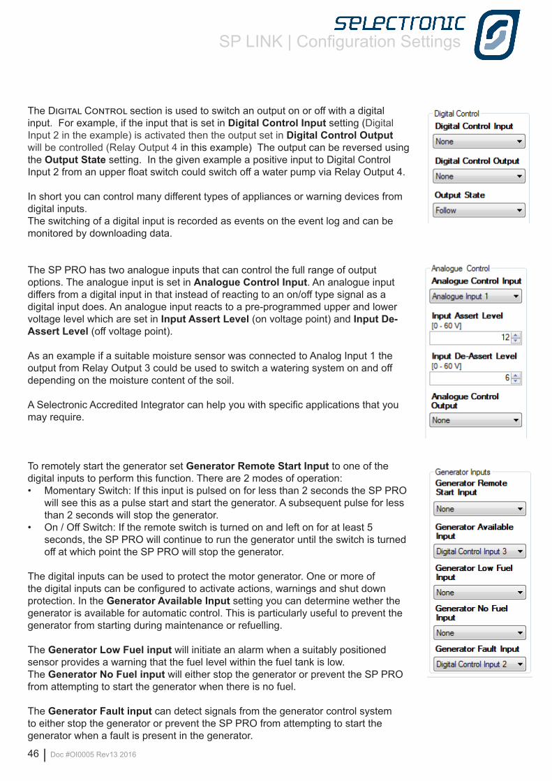
SP LINK | Configuration Settings
46 | Doc #OI0005 Rev13 2016
The Digital Control section is used to switch an output on or off with a digital input. For example, if the input that is set in Digital Control Input setting (Digital Input 2 in the example) is activated then the output set in Digital Control Output will be controlled (Relay Output 4 in this example) The output can be reversed using the Output State setting. In the given example a positive input to Digital Control Input 2 from an upper float switch could switch off a water pump via Relay Output 4.
In short you can control many different types of appliances or warning devices from digital inputs.The switching of a digital input is recorded as events on the event log and can be monitored by downloading data.
The SP PRO has two analogue inputs that can control the full range of output options. The analogue input is set in Analogue Control Input. An analogue input differs from a digital input in that instead of reacting to an on/off type signal as a digital input does. An analogue input reacts to a pre-programmed upper and lower voltage level which are set in Input Assert Level (on voltage point) and Input De-Assert Level (off voltage point).
As an example if a suitable moisture sensor was connected to Analog Input 1 the output from Relay Output 3 could be used to switch a watering system on and off depending on the moisture content of the soil.
A Selectronic Accredited Integrator can help you with specific applications that you may require.
To remotely start the generator set Generator Remote Start Input to one of the digital inputs to perform this function. There are 2 modes of operation: • Momentary Switch: If this input is pulsed on for less than 2 seconds the SP PRO
will see this as a pulse start and start the generator. A subsequent pulse for less than 2 seconds will stop the generator.
• On / Off Switch: If the remote switch is turned on and left on for at least 5 seconds, the SP PRO will continue to run the generator until the switch is turned off at which point the SP PRO will stop the generator.
The digital inputs can be used to protect the motor generator. One or more of the digital inputs can be configured to activate actions, warnings and shut down protection. In the Generator Available Input setting you can determine wether the generator is available for automatic control. This is particularly useful to prevent the generator from starting during maintenance or refuelling.
The Generator Low Fuel input will initiate an alarm when a suitably positioned sensor provides a warning that the fuel level within the fuel tank is low. The Generator No Fuel input will either stop the generator or prevent the SP PRO from attempting to start the generator when there is no fuel.
The Generator Fault input can detect signals from the generator control system to either stop the generator or prevent the SP PRO from attempting to start the generator when a fault is present in the generator.
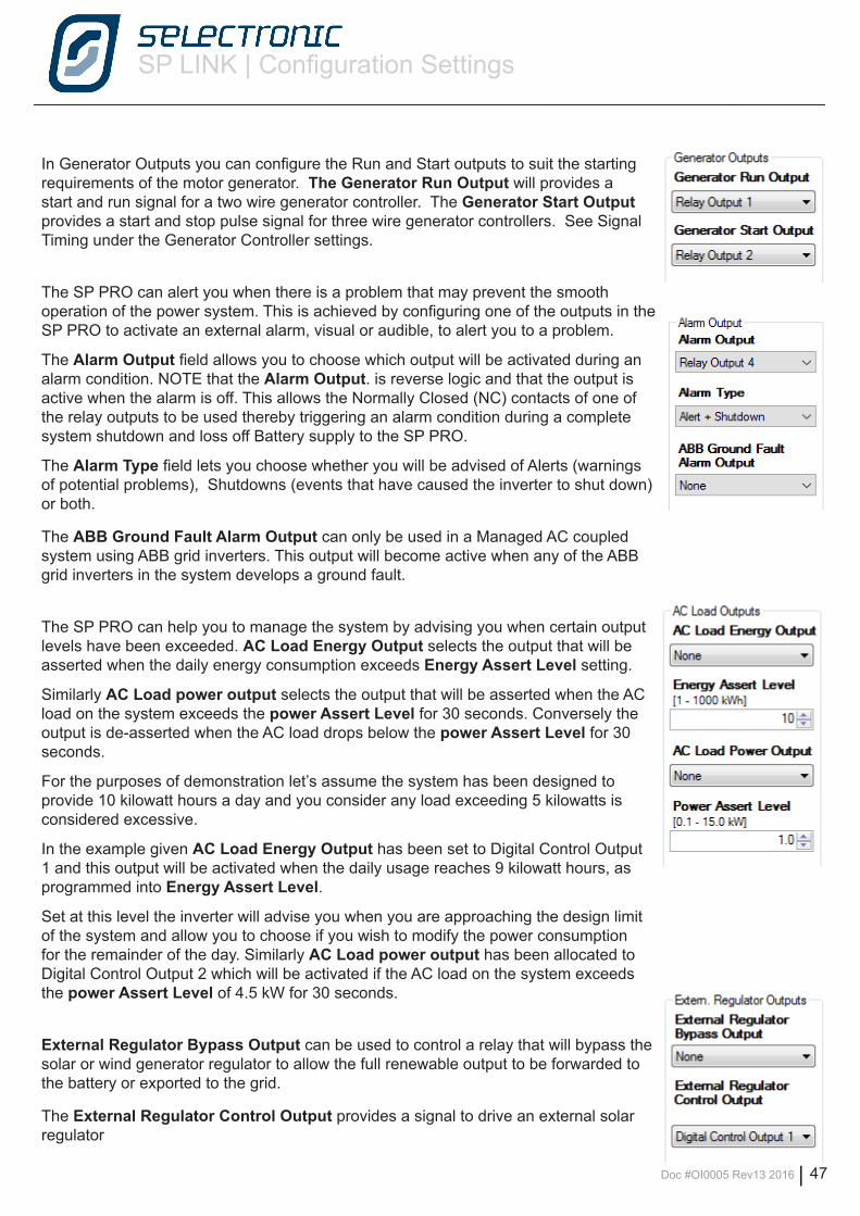
SP LINK | Configuration Settings
Doc #OI0005 Rev13 2016 | 47
In Generator Outputs you can configure the Run and Start outputs to suit the starting requirements of the motor generator. The Generator Run Output will provides a start and run signal for a two wire generator controller. The Generator Start Output provides a start and stop pulse signal for three wire generator controllers. See Signal Timing under the Generator Controller settings.
The SP PRO can alert you when there is a problem that may prevent the smooth operation of the power system. This is achieved by configuring one of the outputs in the SP PRO to activate an external alarm, visual or audible, to alert you to a problem.
The Alarm Output field allows you to choose which output will be activated during an alarm condition. NOTE that the Alarm Output. is reverse logic and that the output is active when the alarm is off. This allows the Normally Closed (NC) contacts of one of the relay outputs to be used thereby triggering an alarm condition during a complete system shutdown and loss off Battery supply to the SP PRO.
The Alarm Type field lets you choose whether you will be advised of Alerts (warnings of potential problems), Shutdowns (events that have caused the inverter to shut down) or both.
The ABB Ground Fault Alarm Output can only be used in a Managed AC coupled system using ABB grid inverters. This output will become active when any of the ABB grid inverters in the system develops a ground fault.
The SP PRO can help you to manage the system by advising you when certain output levels have been exceeded. AC Load Energy Output selects the output that will be asserted when the daily energy consumption exceeds Energy Assert Level setting.
Similarly AC Load power output selects the output that will be asserted when the AC load on the system exceeds the power Assert Level for 30 seconds. Conversely the output is de-asserted when the AC load drops below the power Assert Level for 30 seconds.
For the purposes of demonstration let’s assume the system has been designed to provide 10 kilowatt hours a day and you consider any load exceeding 5 kilowatts is considered excessive.
In the example given AC Load Energy Output has been set to Digital Control Output 1 and this output will be activated when the daily usage reaches 9 kilowatt hours, as programmed into Energy Assert Level.
Set at this level the inverter will advise you when you are approaching the design limit of the system and allow you to choose if you wish to modify the power consumption for the remainder of the day. Similarly AC Load power output has been allocated to Digital Control Output 2 which will be activated if the AC load on the system exceeds the power Assert Level of 4.5 kW for 30 seconds.
External Regulator Bypass Output can be used to control a relay that will bypass the solar or wind generator regulator to allow the full renewable output to be forwarded to the battery or exported to the grid.
The External Regulator Control Output provides a signal to drive an external solar regulator
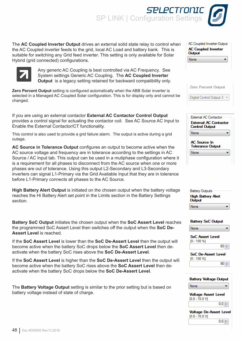
SP LINK | Configuration Settings
48 | Doc #OI0005 Rev13 2016
The AC Coupled Inverter Output drives an external solid state relay to control when the AC Coupled inverter feeds to the grid, local AC Load and battery bank. This is suitable for switching any Grid feed inverter. This setting is only available for Solar Hybrid (grid connected) configurations.
Any generic AC Coupling is best controlled via AC Frequency. See System settings Generic AC Coupling. The AC Coupled Inverter Output is a legacy setting retained for backward compatibility only.
Zero Percent Output setting is configured automatically when the ABB Solar inverter is selected in a Managed AC Coupled Solar configuration. This is for display only and cannot be changed.
If you are using an external contactor External AC Contactor Control Output provides a control signal for actuating the contactor coil. See AC Source AC Input to Enable the External Contactor/CT functionality.
This control is also used to provide a grid failure alarm. The output is active during a grid outage.
AC Source in Tolerance Output configures an output to become active when the AC source voltage and frequency are in tolerance according to the settings in AC Source / AC Input tab. This output can be used in a mutiphase configuration where it is a requirement for all phases to disconnect from the AC source when one or more phases are out of tolerance. Using this output L2-Secondary and L3-Secondary inverters can signal L1-Primary via the Grid Available Input that they are in tolerance before L1-Primary connects all phases to the AC Source.
High Battery Alert Output is initiated on the chosen output when the battery voltage reaches the Hi Battery Alert set point in the Limits section in the Battery Settings section.
Battery SoC Output initiates the chosen output when the SoC Assert Level reaches the programmed SoC Assert Level then switches off the output when the SoC De-Assert Level is reached.
If the SoC Assert Level is lower than the SoC De-Assert Level then the output will become active when the battery SoC drops below the SoC Assert Level then de-activate when the battery SoC rises above the SoC De-Assert Level.
If the SoC Assert Level is higher than the SoC De-Assert Level then the output will become active when the battery SoC rises above the SoC Assert Level then de-activate when the battery SoC drops below the SoC De-Assert Level.
The Battery Voltage Output setting is similar to the prior setting but is based on battery voltage instead of state of charge.
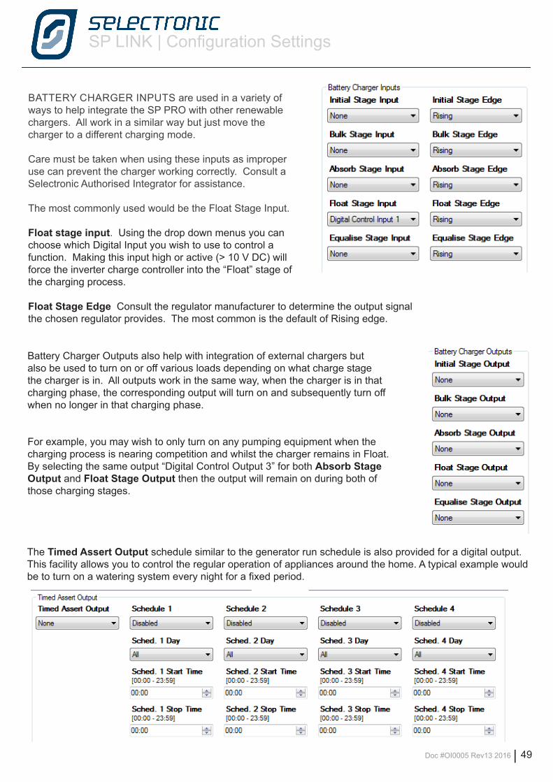
SP LINK | Configuration Settings
Doc #OI0005 Rev13 2016 | 49
BATTERY CHARGER INPUTS are used in a variety of ways to help integrate the SP PRO with other renewable chargers. All work in a similar way but just move the charger to a different charging mode.
Care must be taken when using these inputs as improper use can prevent the charger working correctly. Consult a Selectronic Authorised Integrator for assistance.
The most commonly used would be the Float Stage Input.
Float stage input. Using the drop down menus you can choose which Digital Input you wish to use to control a function. Making this input high or active (> 10 V DC) will force the inverter charge controller into the “Float” stage of the charging process.
Float Stage Edge Consult the regulator manufacturer to determine the output signal the chosen regulator provides. The most common is the default of Rising edge.
Battery Charger Outputs also help with integration of external chargers but also be used to turn on or off various loads depending on what charge stage the charger is in. All outputs work in the same way, when the charger is in that charging phase, the corresponding output will turn on and subsequently turn off when no longer in that charging phase.
For example, you may wish to only turn on any pumping equipment when the charging process is nearing competition and whilst the charger remains in Float. By selecting the same output “Digital Control Output 3” for both Absorb Stage Output and Float Stage Output then the output will remain on during both of those charging stages.
The Timed Assert Output schedule similar to the generator run schedule is also provided for a digital output. This facility allows you to control the regular operation of appliances around the home. A typical example would be to turn on a watering system every night for a fixed period.
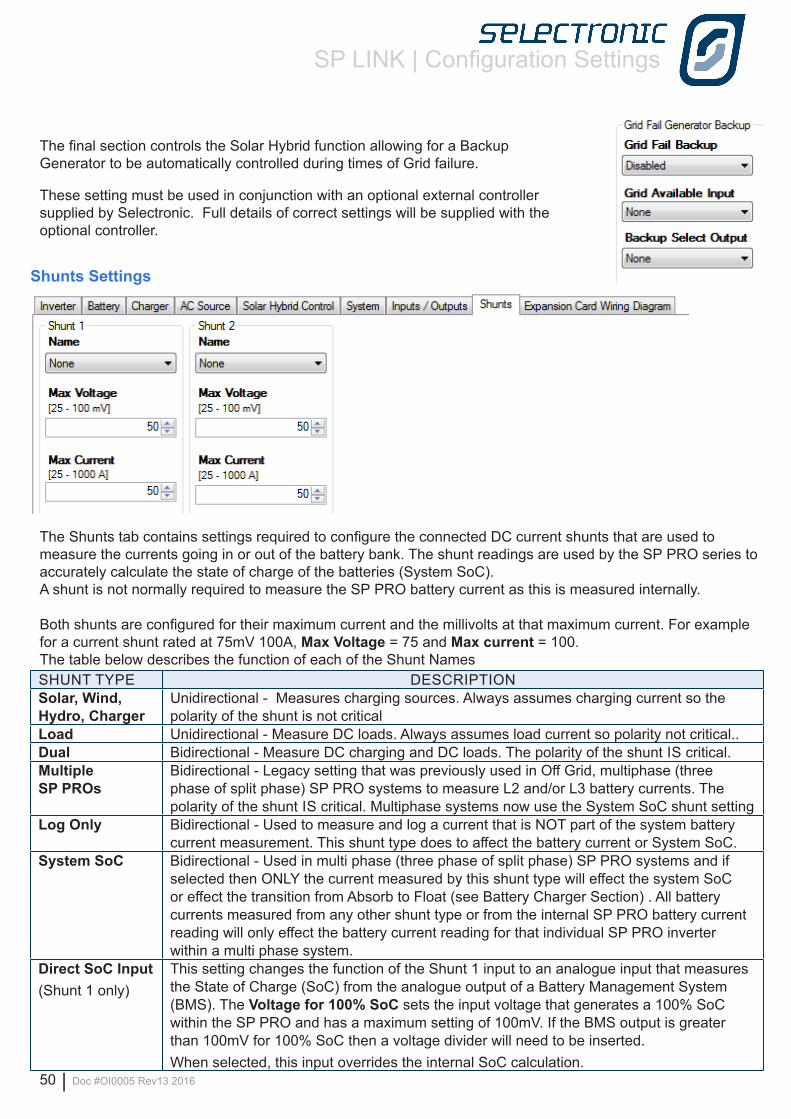
SP LINK | Configuration Settings
50 | Doc #OI0005 Rev13 2016
The final section controls the Solar Hybrid function allowing for a Backup Generator to be automatically controlled during times of Grid failure.
These setting must be used in conjunction with an optional external controller supplied by Selectronic. Full details of correct settings will be supplied with the optional controller.
Shunts Settings
The Shunts tab contains settings required to configure the connected DC current shunts that are used to measure the currents going in or out of the battery bank. The shunt readings are used by the SP PRO series to accurately calculate the state of charge of the batteries (System SoC). A shunt is not normally required to measure the SP PRO battery current as this is measured internally.
Both shunts are configured for their maximum current and the millivolts at that maximum current. For example for a current shunt rated at 75mV 100A, Max Voltage = 75 and Max current = 100.The table below describes the function of each of the Shunt Names SHUNT TYPE DESCRIPTIONSolar, Wind, Hydro, Charger
Unidirectional - Measures charging sources. Always assumes charging current so the polarity of the shunt is not critical
Load Unidirectional - Measure DC loads. Always assumes load current so polarity not critical..Dual Bidirectional - Measure DC charging and DC loads. The polarity of the shunt IS critical.Multiple SP PROs
Bidirectional - Legacy setting that was previously used in Off Grid, multiphase (three phase of split phase) SP PRO systems to measure L2 and/or L3 battery currents. The polarity of the shunt IS critical. Multiphase systems now use the System SoC shunt setting
Log Only Bidirectional - Used to measure and log a current that is NOT part of the system battery current measurement. This shunt type does to affect the battery current or System SoC.
System SoC Bidirectional - Used in multi phase (three phase of split phase) SP PRO systems and if selected then ONLY the current measured by this shunt type will effect the system SoC or effect the transition from Absorb to Float (see Battery Charger Section) . All battery currents measured from any other shunt type or from the internal SP PRO battery current reading will only effect the battery current reading for that individual SP PRO inverter within a multi phase system.
Direct SoC Input(Shunt 1 only)
This setting changes the function of the Shunt 1 input to an analogue input that measures the State of Charge (SoC) from the analogue output of a Battery Management System (BMS). The Voltage for 100% SoC sets the input voltage that generates a 100% SoC within the SP PRO and has a maximum setting of 100mV. If the BMS output is greater than 100mV for 100% SoC then a voltage divider will need to be inserted.When selected, this input overrides the internal SoC calculation.
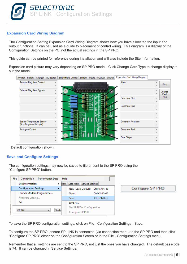
SP LINK | Configuration Settings
Doc #OI0005 Rev13 2016 | 51
Expansion Card Wiring Diagram
The Configuration Setting Expansion Card Wiring Diagram shows how you have allocated the input and output functions. It can be used as a guide to placement of control wiring. This diagram is a display of the Configuration Settings on the PC, not the actual settings in the SP PRO.
This guide can be printed for reference during installation and will also include the Site Information.
Expansion card picture may vary depending on SP PRO model. Click Change Card Type to change display to suit the model.
Default configuration shown.
Save and Configure Settings
The configuration settings may now be saved to file or sent to the SP PRO using the“Configure SP PRO” button.
To save the SP PRO configuration settings, click on File - Configuration Settings - Save.
To configure the SP PRO, ensure SP LINK is connected (via connection menu) to the SP PRO and then click “Configure SP PRO” either on the Configuration Screen or in the File - Configuration Settings menu.
Remember that all settings are sent to the SP PRO, not just the ones you have changed. The default passcode is 74. It can be changed in Service Settings.
SP LINK | Performance Monitoring
52 | Doc #OI0005 Rev13 2016
Performance Monitoring
SP LINK provides a number of options to monitor in real time or review the history of all modes of operation of the power system. These options are -
• Customer Interface Quick View - real time summary of SP PRO system
• Integrator / User Interface Data View - real time detailed information of what is occurring Now, Today and what has occurred Historically
• Integrator / User information Performance Data Historical records for displaying graphically
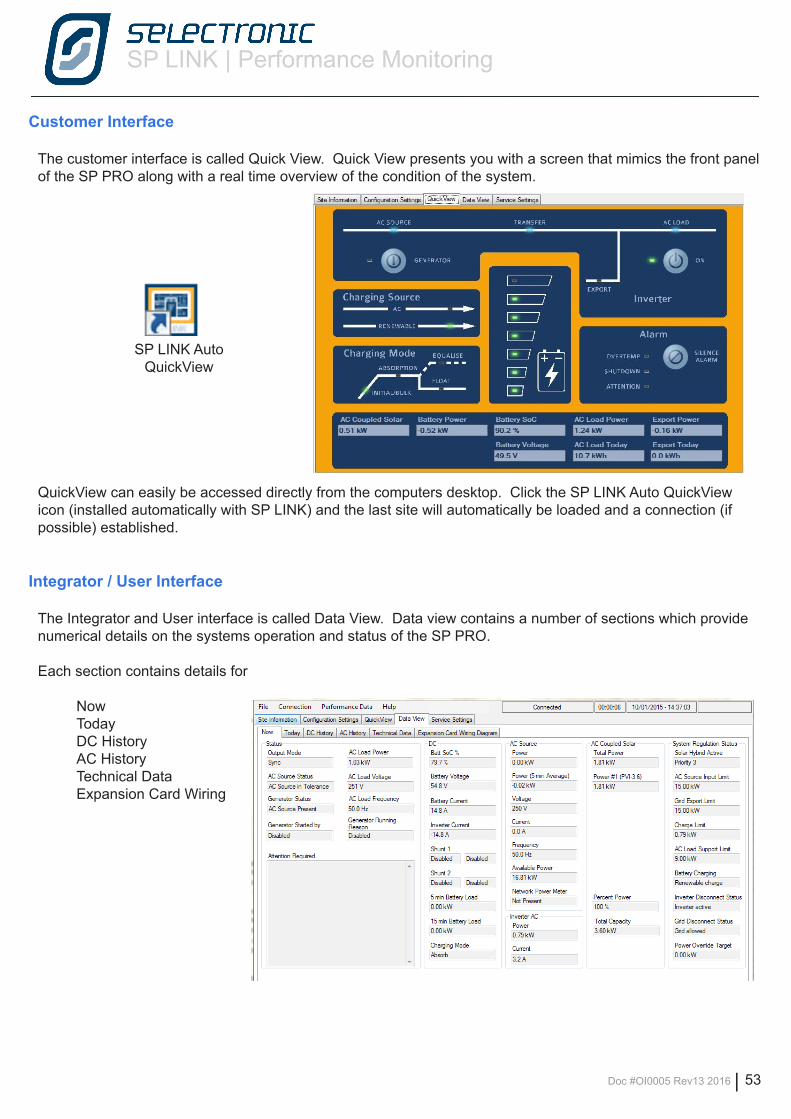
SP LINK | Performance Monitoring
Doc #OI0005 Rev13 2016 | 53
Customer Interface
The customer interface is called Quick View. Quick View presents you with a screen that mimics the front panel of the SP PRO along with a real time overview of the condition of the system.
QuickView can easily be accessed directly from the computers desktop. Click the SP LINK Auto QuickView icon (installed automatically with SP LINK) and the last site will automatically be loaded and a connection (if possible) established.
Integrator / User Interface
The Integrator and User interface is called Data View. Data view contains a number of sections which provide numerical details on the systems operation and status of the SP PRO.
Each section contains details for
Now Today DC History AC History Technical Data Expansion Card Wiring
SP LINK AutoQuickView
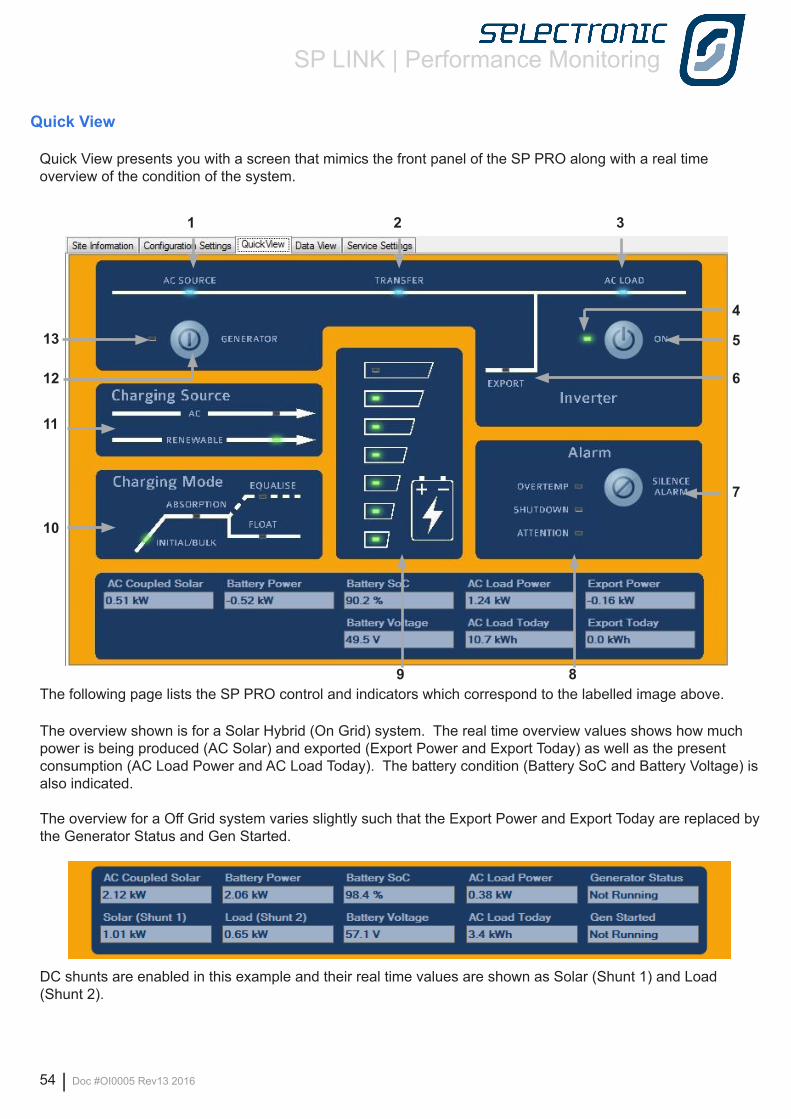
SP LINK | Performance Monitoring
54 | Doc #OI0005 Rev13 2016
1 2 3
4
5
6
7
89
10
11
12
13
Quick View
Quick View presents you with a screen that mimics the front panel of the SP PRO along with a real time overview of the condition of the system.
The following page lists the SP PRO control and indicators which correspond to the labelled image above.
The overview shown is for a Solar Hybrid (On Grid) system. The real time overview values shows how much power is being produced (AC Solar) and exported (Export Power and Export Today) as well as the present consumption (AC Load Power and AC Load Today). The battery condition (Battery SoC and Battery Voltage) is also indicated.
The overview for a Off Grid system varies slightly such that the Export Power and Export Today are replaced by the Generator Status and Gen Started.
DC shunts are enabled in this example and their real time values are shown as Solar (Shunt 1) and Load (Shunt 2).
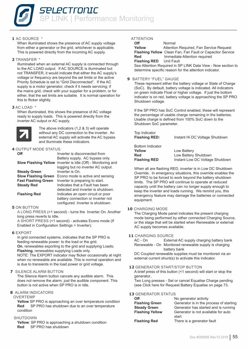
SP LINK | Performance Monitoring
Doc #OI0005 Rev13 2016 | 55
1 AC SOURCE *When illuminated shows the presence of AC supply voltage from either a generator or the grid, whichever is applicable. This is powered directly from the incoming AC supply.
2 TRANSFER *Illuminated when an external AC supply is connected through to the AC LOAD output. If AC SOURCE is illuminated but not TRANSFER, it would indicate that either the AC supply’s voltage or frequency are beyond the set limits or the active Priority Schedule is set to “Grid Disconnected”. If the AC supply is a motor generator, check if it needs servicing; if the mains grid, check with your supplier for a problem, or for either, that the set limits are suitable. It is normal operation for this to flicker slightly.
3 AC LOAD *When illuminated, this shows the presence of AC voltage ready to supply loads. This is powered directly from the inverter AC output or AC supply.
The above indicators (1,2 & 3) will operate without any DC connection to the inverter. An external AC supply will activate the AC bypass and illuminate these indicators.
4 OUTPUT MODE STATUSOff Inverter is disconnected from Battery supply. AC bypass only.Slow Flashing Yellow Inverter is Idle (Off) - Monitoring and logging but no inverter AC output.Steady Green Inverter is On.Slow Flashing Green Econo mode is active and sensingFast Flashing Green Inverter is preparing to start.Steady Red Indicates that a Fault has been detected and inverter is shutdown.Flashing Red Indicates an open circuit or poor battery connection or inverter not configured. Inverter is shutdown.
5 ON BUTTON A LONG PRESS (>1 second) - turns the Inverter On. Another long press reverts to Idle.A SHORT PRESS (<1 second) - activates Econo mode (If Enabled in Configuration Settings > Inverter).
6 EXPORTIn grid connected systems, indicates that the SP PRO is feeding renewable power: to the load or the grid. On, renewables exporting to the grid and supplying Loads; Flashing, renewables supplying Loads only.NOTE: The EXPORT indicator may flicker occasionally at night when no renewable are available. This is normal operation and is due to transients in the load power or grid voltage.
7 SILENCE ALARM BUTTONThe Silence Alarm button cancels any audible alarm. This does not remove the alarm, just the audible component. This button is not active when SP PRO is in Idle.
8 ALARM INDICATORS OVERTEMP
Yellow SP PRO is approaching an over temperature conditionRed SP PRO has shutdown due to an over temperature condition
SHUTDOWN Yellow: SP PRO is approaching a shutdown conditionRed SP PRO has shutdown
ATTENTION Off NormalYellow Attention Required, Fan Service RequestFlashing Yellow Clean Fan, Fan Fault or Capacitor ServiceRed Immediate Attention requiredFlashing RED Unit FaultSee Attention Required in SP LINK Data View - Now section to determine specific reason for the attention indicator.
9 BATTERY “FUEL” GAUGE These represent either the battery voltage or State of Charge (SoC). By default, battery voltage is indicated. All indicators on green indicate Float or higher voltage. If just the bottom indicator is on red, battery voltage is approaching the SP PRO Shutdown voltage.
If the SP PRO has SoC Control enabled, these will represent the percentage of usable charge remaining in the batteries. Usable charge is defined from 100% SoC down to the Shutdown SoC parameter.
Top Indicator Flashing RED: Instant Hi DC Voltage Shutdown
Bottom IndicatorYellow Low BatteryRed Low Battery ShutdownFlashing RED Instant Low DC Voltage Shutdown
When all are flashing RED, inverter is in Low DC Shutdown Override. In emergency situations, this override enables the SP PRO to be forced to work beyond the battery shutdown limits. The SP PRO will continue to operate at reduced capacity until the battery can no longer supply enough to keep the inverter and loads running. We remind you, this emergency feature may damage the batteries or connected equipment.
10 CHARGING MODEThe Charging Mode panel indicates the present charging mode being performed by either connected Charging Source, or the stage that will be started when Renewable or external AC supply becomes available.
11 CHARGING SOURCEAC - On External AC supply charging battery bankRenewable - On Monitored renewable supply is charging
battery bankDC Coupled renewable supplies must be monitored via an external current shunt(s) to activate this indicator.
12 GENERATOR START/STOP BUTTON A brief press of this button (<1 second) will start or stop the generator..Two Long presses - Set or cancel Equalise Charge pending (see Click here for Request Battery Equalise on page 73.
13 GENERATOR STATUSOff No generator activityFlashing Green Generator is in the process of starting Steady Green Generator has started and is runningFlashing Yellow Generator is not available for auto startFlashing Red There is a generator fault
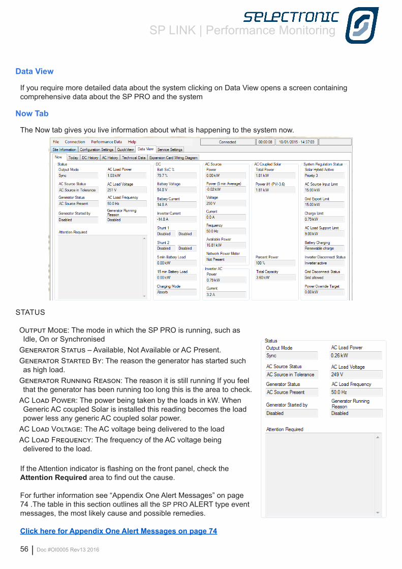
SP LINK | Performance Monitoring
56 | Doc #OI0005 Rev13 2016
STATUS
Output Mode: The mode in which the SP PRO is running, such as Idle, On or Synchronised
Generator Status – Available, Not Available or AC Present.Generator Started By: The reason the generator has started such as high load.
Generator Running Reason: The reason it is still running If you feel that the generator has been running too long this is the area to check.
AC Load Power: The power being taken by the loads in kW. When Generic AC coupled Solar is installed this reading becomes the load power less any generic AC coupled solar power.
AC Load Voltage: The AC voltage being delivered to the load AC Load Frequency: The frequency of the AC voltage being delivered to the load.
If the Attention indicator is flashing on the front panel, check the Attention Required area to find out the cause.
For further information see “Appendix One Alert Messages” on page 74 .The table in this section outlines all the SP PRO ALERT type event messages, the most likely cause and possible remedies.
Click here for Appendix One Alert Messages on page 74
Data View
If you require more detailed data about the system clicking on Data View opens a screen containing comprehensive data about the SP PRO and the system
Now Tab
The Now tab gives you live information about what is happening to the system now.
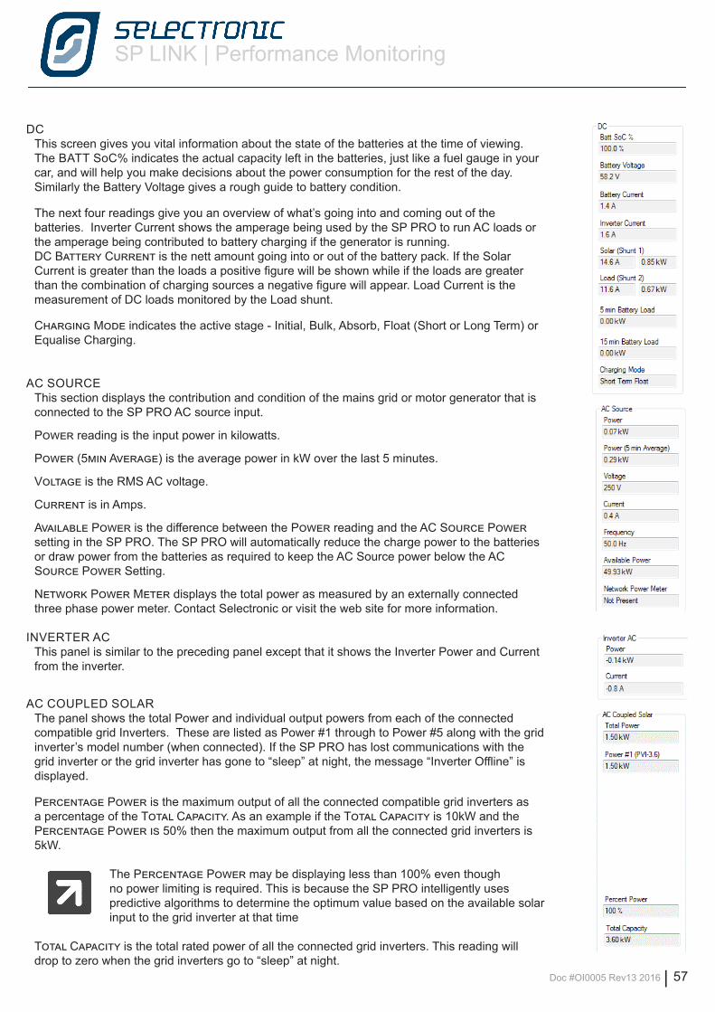
SP LINK | Performance Monitoring
Doc #OI0005 Rev13 2016 | 57
DCThis screen gives you vital information about the state of the batteries at the time of viewing.The BATT SoC% indicates the actual capacity left in the batteries, just like a fuel gauge in your car, and will help you make decisions about the power consumption for the rest of the day. Similarly the Battery Voltage gives a rough guide to battery condition.
The next four readings give you an overview of what’s going into and coming out of the batteries. Inverter Current shows the amperage being used by the SP PRO to run AC loads or the amperage being contributed to battery charging if the generator is running. DC Battery Current is the nett amount going into or out of the battery pack. If the Solar Current is greater than the loads a positive figure will be shown while if the loads are greater than the combination of charging sources a negative figure will appear. Load Current is the measurement of DC loads monitored by the Load shunt.
Charging Mode indicates the active stage - Initial, Bulk, Absorb, Float (Short or Long Term) or Equalise Charging.
AC SOURCEThis section displays the contribution and condition of the mains grid or motor generator that is connected to the SP PRO AC source input.
Power reading is the input power in kilowatts.
Power (5min Average) is the average power in kW over the last 5 minutes.
Voltage is the RMS AC voltage.
Current is in Amps.
Available Power is the difference between the Power reading and the AC Source Power setting in the SP PRO. The SP PRO will automatically reduce the charge power to the batteries or draw power from the batteries as required to keep the AC Source power below the AC Source Power Setting.
Network Power Meter displays the total power as measured by an externally connected three phase power meter. Contact Selectronic or visit the web site for more information.
INVERTER ACThis panel is similar to the preceding panel except that it shows the Inverter Power and Current from the inverter.
AC COUPLED SOLARThe panel shows the total Power and individual output powers from each of the connected compatible grid Inverters. These are listed as Power #1 through to Power #5 along with the grid inverter’s model number (when connected). If the SP PRO has lost communications with the grid inverter or the grid inverter has gone to “sleep” at night, the message “Inverter Offline” is displayed.
Percentage Power is the maximum output of all the connected compatible grid inverters as a percentage of the Total Capacity. As an example if the Total Capacity is 10kW and the Percentage Power is 50% then the maximum output from all the connected grid inverters is 5kW.
The Percentage Power may be displaying less than 100% even though no power limiting is required. This is because the SP PRO intelligently uses predictive algorithms to determine the optimum value based on the available solar input to the grid inverter at that time
Total Capacity is the total rated power of all the connected grid inverters. This reading will drop to zero when the grid inverters go to “sleep” at night.
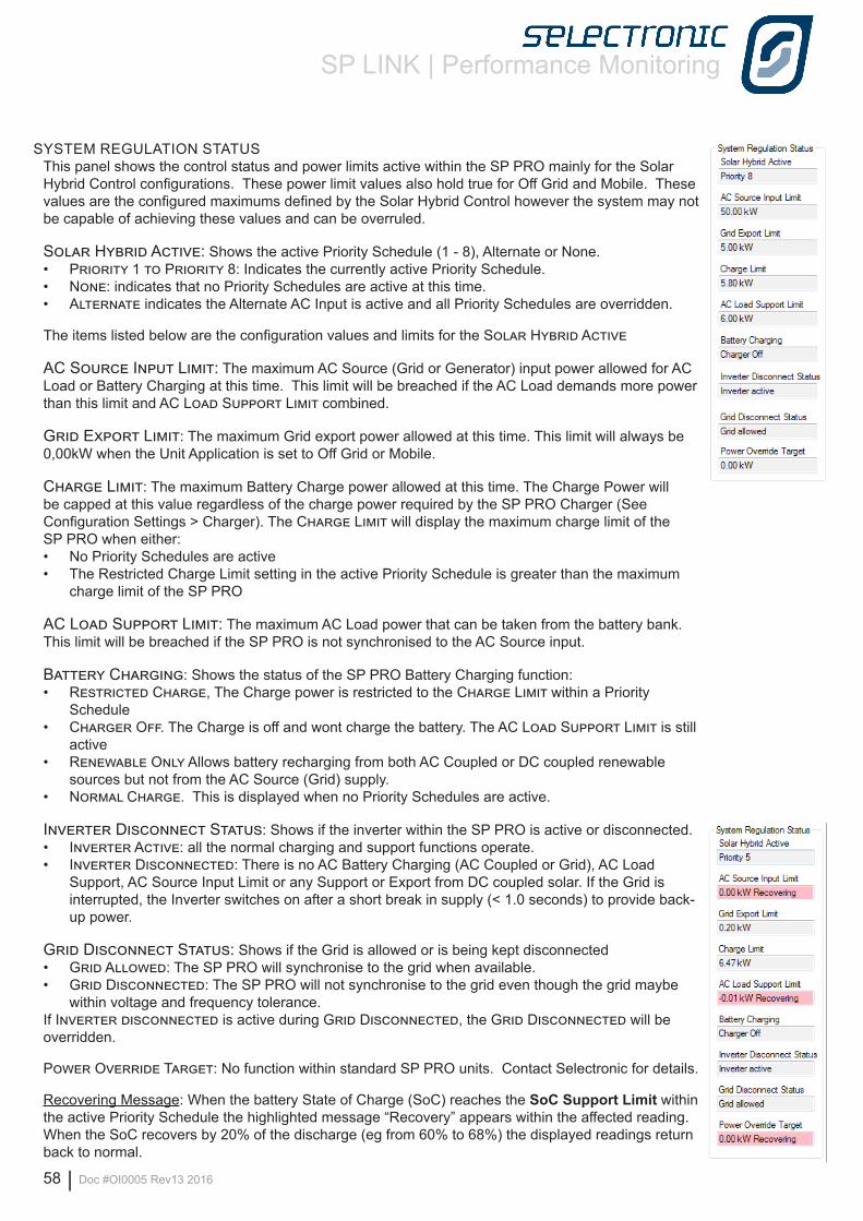
SP LINK | Performance Monitoring
58 | Doc #OI0005 Rev13 2016
SYSTEM REGULATION STATUSThis panel shows the control status and power limits active within the SP PRO mainly for the Solar Hybrid Control configurations. These power limit values also hold true for Off Grid and Mobile. These values are the configured maximums defined by the Solar Hybrid Control however the system may not be capable of achieving these values and can be overruled.
Solar Hybrid Active: Shows the active Priority Schedule (1 - 8), Alternate or None. • Priority 1 to Priority 8: Indicates the currently active Priority Schedule.• None: indicates that no Priority Schedules are active at this time. • Alternate indicates the Alternate AC Input is active and all Priority Schedules are overridden.
The items listed below are the configuration values and limits for the Solar Hybrid Active
AC Source Input Limit: The maximum AC Source (Grid or Generator) input power allowed for AC Load or Battery Charging at this time. This limit will be breached if the AC Load demands more power than this limit and AC Load Support Limit combined.
Grid Export Limit: The maximum Grid export power allowed at this time. This limit will always be 0,00kW when the Unit Application is set to Off Grid or Mobile.
Charge Limit: The maximum Battery Charge power allowed at this time. The Charge Power will be capped at this value regardless of the charge power required by the SP PRO Charger (See Configuration Settings > Charger). The Charge Limit will display the maximum charge limit of the SP PRO when either:• No Priority Schedules are active• The Restricted Charge Limit setting in the active Priority Schedule is greater than the maximum
charge limit of the SP PRO
AC Load Support Limit: The maximum AC Load power that can be taken from the battery bank. This limit will be breached if the SP PRO is not synchronised to the AC Source input.
Battery Charging: Shows the status of the SP PRO Battery Charging function: • Restricted Charge, The Charge power is restricted to the Charge Limit within a Priority
Schedule• Charger Off. The Charge is off and wont charge the battery. The AC Load Support Limit is still
active• Renewable Only Allows battery recharging from both AC Coupled or DC coupled renewable
sources but not from the AC Source (Grid) supply.• Normal Charge. This is displayed when no Priority Schedules are active.
Inverter Disconnect Status: Shows if the inverter within the SP PRO is active or disconnected.• Inverter Active: all the normal charging and support functions operate.• Inverter Disconnected: There is no AC Battery Charging (AC Coupled or Grid), AC Load
Support, AC Source Input Limit or any Support or Export from DC coupled solar. If the Grid is interrupted, the Inverter switches on after a short break in supply (< 1.0 seconds) to provide back-up power.
Grid Disconnect Status: Shows if the Grid is allowed or is being kept disconnected • Grid Allowed: The SP PRO will synchronise to the grid when available.• Grid Disconnected: The SP PRO will not synchronise to the grid even though the grid maybe
within voltage and frequency tolerance.If Inverter disconnected is active during Grid Disconnected, the Grid Disconnected will be overridden.
Power Override Target: No function within standard SP PRO units. Contact Selectronic for details.
Recovering Message: When the battery State of Charge (SoC) reaches the SoC Support Limit within the active Priority Schedule the highlighted message “Recovery” appears within the affected reading. When the SoC recovers by 20% of the discharge (eg from 60% to 68%) the displayed readings return back to normal.
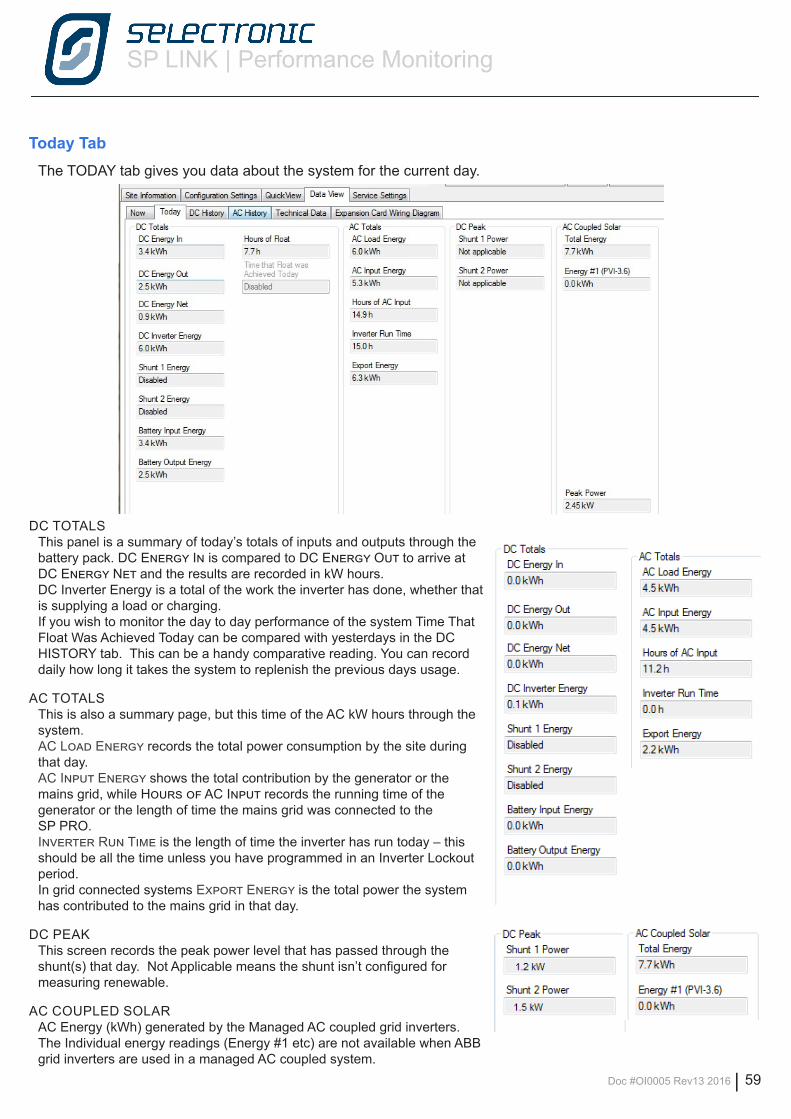
SP LINK | Performance Monitoring
Doc #OI0005 Rev13 2016 | 59
DC TOTALSThis panel is a summary of today’s totals of inputs and outputs through the battery pack. DC Energy In is compared to DC Energy Out to arrive at DC Energy Net and the results are recorded in kW hours.DC Inverter Energy is a total of the work the inverter has done, whether that is supplying a load or charging.If you wish to monitor the day to day performance of the system Time That Float Was Achieved Today can be compared with yesterdays in the DC HISTORY tab. This can be a handy comparative reading. You can record daily how long it takes the system to replenish the previous days usage.
AC TOTALSThis is also a summary page, but this time of the AC kW hours through the system. AC Load Energy records the total power consumption by the site during that day.AC Input Energy shows the total contribution by the generator or the mains grid, while Hours of AC Input records the running time of the generator or the length of time the mains grid was connected to the SP PRO.Inverter Run Time is the length of time the inverter has run today – this should be all the time unless you have programmed in an Inverter Lockout period.In grid connected systems Export Energy is the total power the system has contributed to the mains grid in that day.
DC PEAKThis screen records the peak power level that has passed through the shunt(s) that day. Not Applicable means the shunt isn’t configured for measuring renewable.
AC COUPLED SOLARAC Energy (kWh) generated by the Managed AC coupled grid inverters.The Individual energy readings (Energy #1 etc) are not available when ABB grid inverters are used in a managed AC coupled system.
Today TabThe TODAY tab gives you data about the system for the current day.
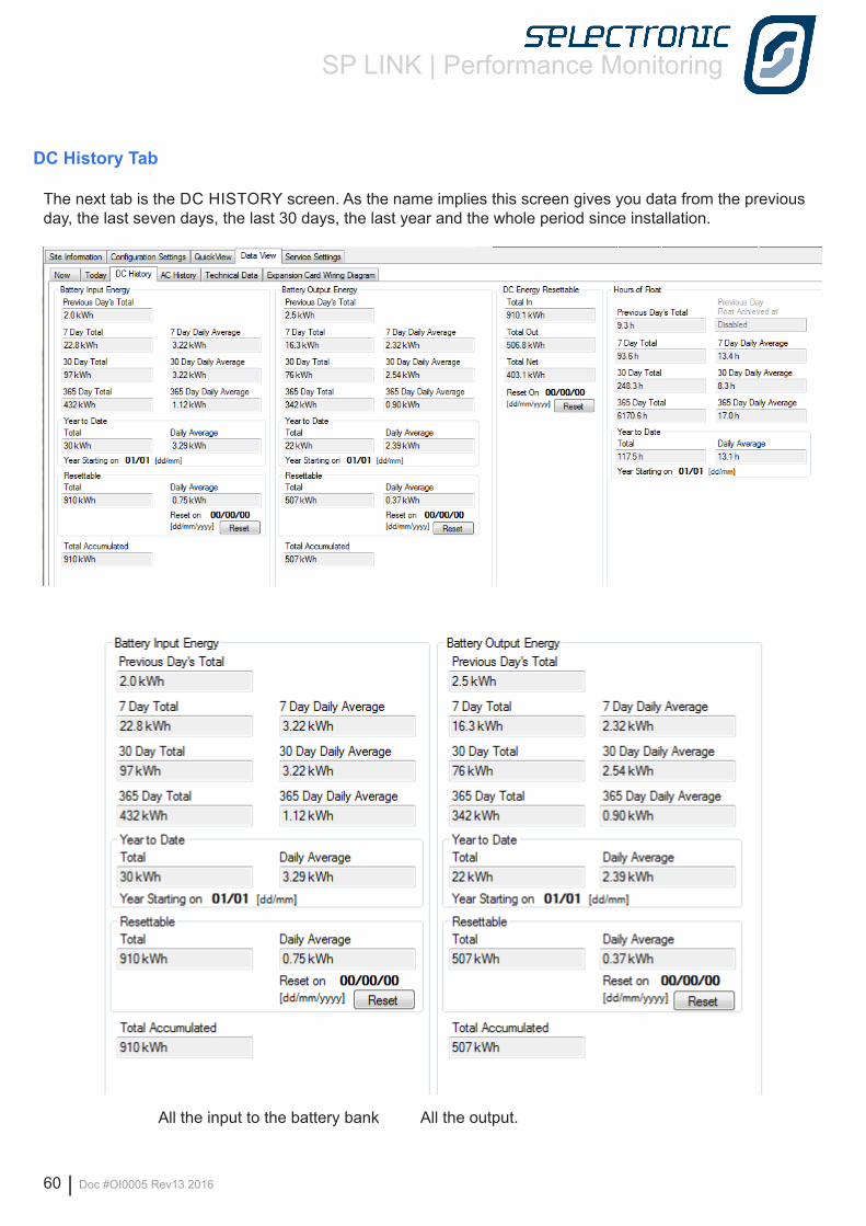
SP LINK | Performance Monitoring
60 | Doc #OI0005 Rev13 2016
DC History Tab
The next tab is the DC HISTORY screen. As the name implies this screen gives you data from the previous day, the last seven days, the last 30 days, the last year and the whole period since installation.
All the input to the battery bank All the output.
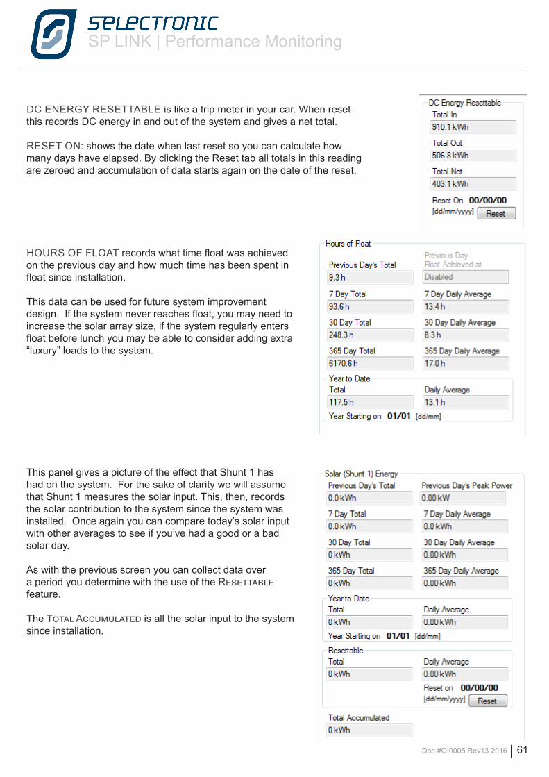
SP LINK | Performance Monitoring
Doc #OI0005 Rev13 2016 | 61
DC ENERGY RESETTABLE is like a trip meter in your car. When reset this records DC energy in and out of the system and gives a net total.
RESET ON: shows the date when last reset so you can calculate how many days have elapsed. By clicking the Reset tab all totals in this reading are zeroed and accumulation of data starts again on the date of the reset.
HOURS OF FLOAT records what time float was achieved on the previous day and how much time has been spent in float since installation.
This data can be used for future system improvement design. If the system never reaches float, you may need to increase the solar array size, if the system regularly enters float before lunch you may be able to consider adding extra “luxury” loads to the system.
This panel gives a picture of the effect that Shunt 1 has had on the system. For the sake of clarity we will assume that Shunt 1 measures the solar input. This, then, records the solar contribution to the system since the system was installed. Once again you can compare today’s solar input with other averages to see if you’ve had a good or a bad solar day.
As with the previous screen you can collect data over a period you determine with the use of the Resettable feature.
The Total Accumulated is all the solar input to the system since installation.
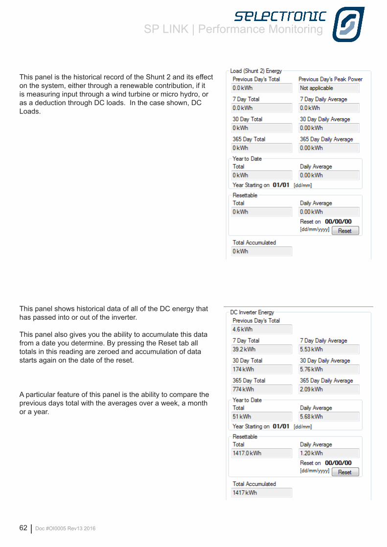
SP LINK | Performance Monitoring
62 | Doc #OI0005 Rev13 2016
This panel is the historical record of the Shunt 2 and its effect on the system, either through a renewable contribution, if it is measuring input through a wind turbine or micro hydro, or as a deduction through DC loads. In the case shown, DC Loads.
This panel shows historical data of all of the DC energy that has passed into or out of the inverter.
This panel also gives you the ability to accumulate this data from a date you determine. By pressing the Reset tab all totals in this reading are zeroed and accumulation of data starts again on the date of the reset.
A particular feature of this panel is the ability to compare the previous days total with the averages over a week, a month or a year.

SP LINK | Performance Monitoring
Doc #OI0005 Rev13 2016 | 63
This is a record of the total AC loads presented by the home to the power system.
This is the total AC input contributed by the motor generator or by the mains grid.
AC History Tab
The AC HISTORY SCREEN, as with the DC History screen gives you data from the previous day, the last seven days, the last 30 days, the last year and the whole period since installation
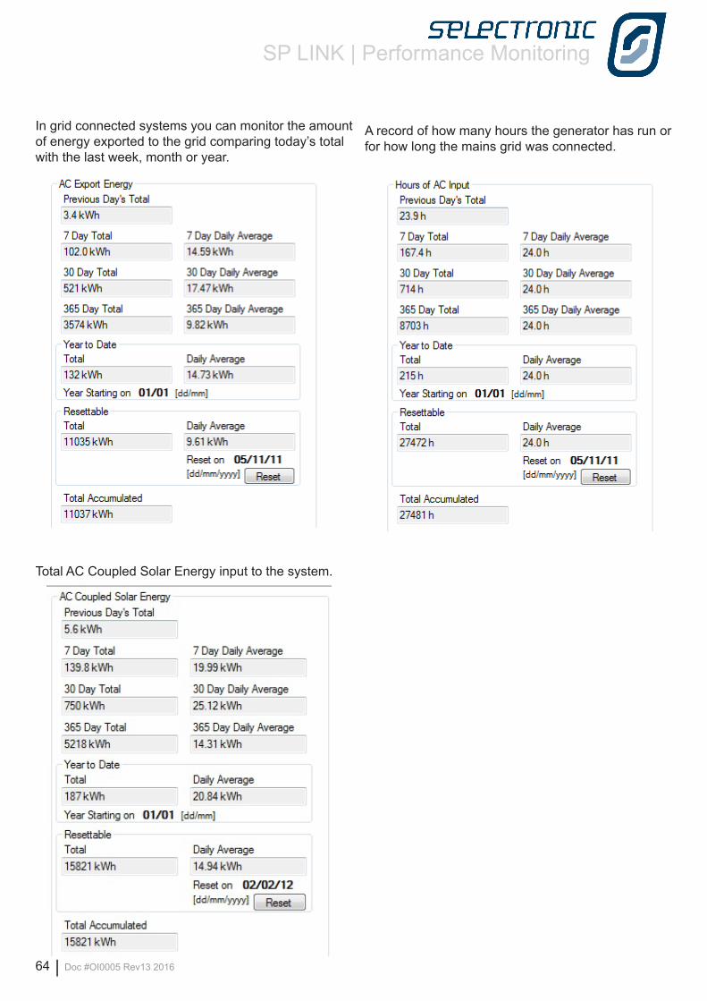
SP LINK | Performance Monitoring
64 | Doc #OI0005 Rev13 2016
A record of how many hours the generator has run or for how long the mains grid was connected.
In grid connected systems you can monitor the amount of energy exported to the grid comparing today’s total with the last week, month or year.
Total AC Coupled Solar Energy input to the system.
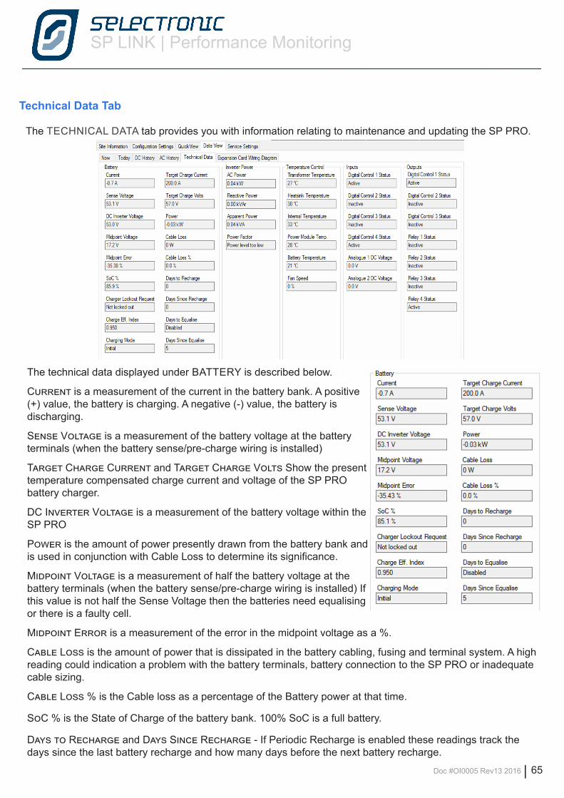
SP LINK | Performance Monitoring
Doc #OI0005 Rev13 2016 | 65
Technical Data Tab
The TECHNICAL DATA tab provides you with information relating to maintenance and updating the SP PRO.
The technical data displayed under BATTERY is described below.
Current is a measurement of the current in the battery bank. A positive (+) value, the battery is charging. A negative (-) value, the battery is discharging.
Sense Voltage is a measurement of the battery voltage at the battery terminals (when the battery sense/pre-charge wiring is installed)
Target Charge Current and Target Charge Volts Show the present temperature compensated charge current and voltage of the SP PRO battery charger.
DC Inverter Voltage is a measurement of the battery voltage within the SP PRO
Power is the amount of power presently drawn from the battery bank and is used in conjunction with Cable Loss to determine its significance.
Midpoint Voltage is a measurement of half the battery voltage at the battery terminals (when the battery sense/pre-charge wiring is installed) If this value is not half the Sense Voltage then the batteries need equalising or there is a faulty cell.
Midpoint Error is a measurement of the error in the midpoint voltage as a %.
Cable Loss is the amount of power that is dissipated in the battery cabling, fusing and terminal system. A high reading could indication a problem with the battery terminals, battery connection to the SP PRO or inadequate cable sizing.
Cable Loss % is the Cable loss as a percentage of the Battery power at that time.
SoC % is the State of Charge of the battery bank. 100% SoC is a full battery.
Days to Recharge and Days Since Recharge - If Periodic Recharge is enabled these readings track the days since the last battery recharge and how many days before the next battery recharge.
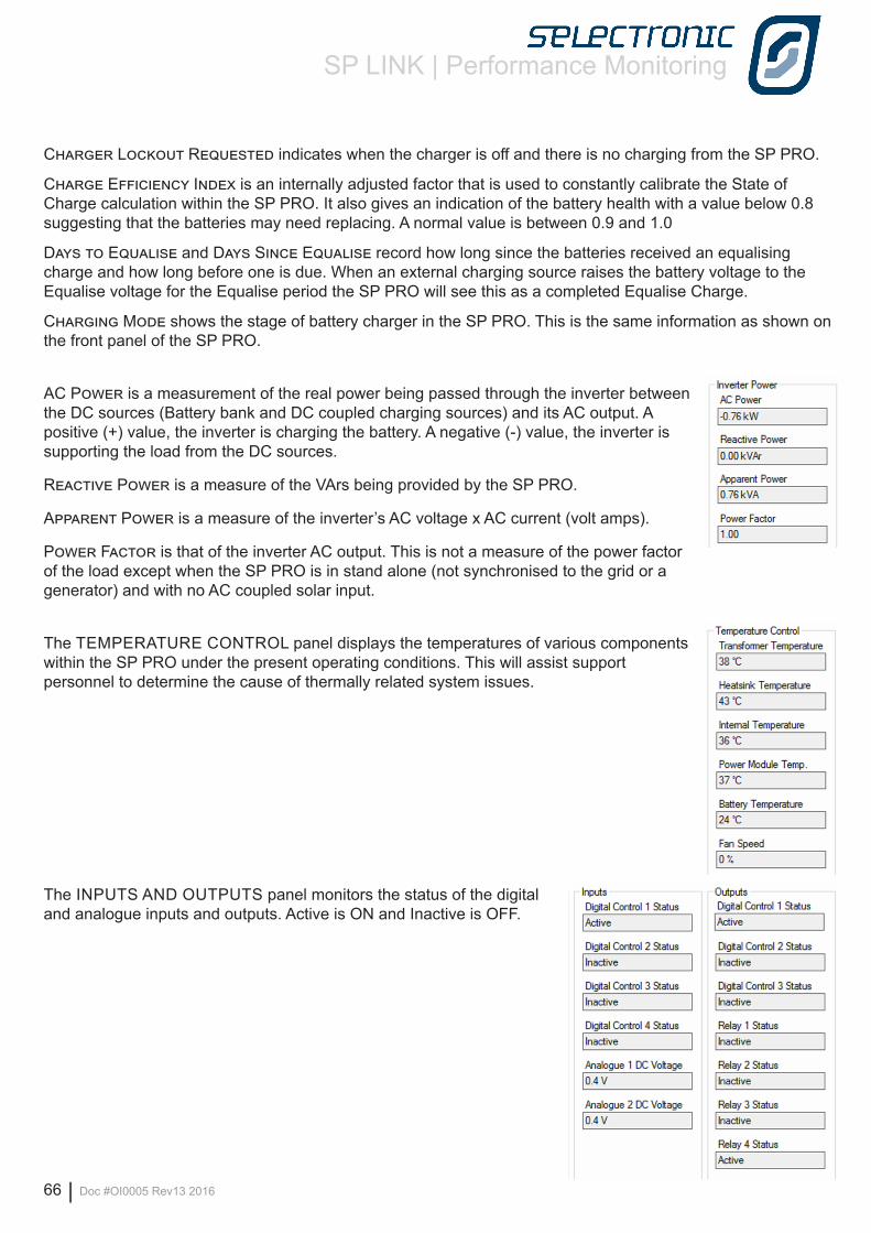
SP LINK | Performance Monitoring
66 | Doc #OI0005 Rev13 2016
Charger Lockout Requested indicates when the charger is off and there is no charging from the SP PRO.
Charge Efficiency Index is an internally adjusted factor that is used to constantly calibrate the State of Charge calculation within the SP PRO. It also gives an indication of the battery health with a value below 0.8 suggesting that the batteries may need replacing. A normal value is between 0.9 and 1.0
Days to Equalise and Days Since Equalise record how long since the batteries received an equalising charge and how long before one is due. When an external charging source raises the battery voltage to the Equalise voltage for the Equalise period the SP PRO will see this as a completed Equalise Charge.
Charging Mode shows the stage of battery charger in the SP PRO. This is the same information as shown on the front panel of the SP PRO.
AC Power is a measurement of the real power being passed through the inverter between the DC sources (Battery bank and DC coupled charging sources) and its AC output. A positive (+) value, the inverter is charging the battery. A negative (-) value, the inverter is supporting the load from the DC sources.
Reactive Power is a measure of the VArs being provided by the SP PRO.
Apparent Power is a measure of the inverter’s AC voltage x AC current (volt amps).
Power Factor is that of the inverter AC output. This is not a measure of the power factor of the load except when the SP PRO is in stand alone (not synchronised to the grid or a generator) and with no AC coupled solar input.
The TEMPERATURE CONTROL panel displays the temperatures of various components within the SP PRO under the present operating conditions. This will assist support personnel to determine the cause of thermally related system issues.
The INPUTS AND OUTPUTS panel monitors the status of the digital and analogue inputs and outputs. Active is ON and Inactive is OFF.
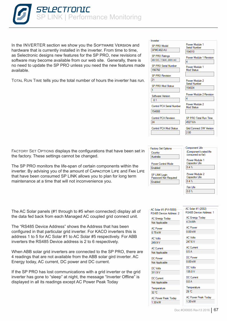
SP LINK | Performance Monitoring
Doc #OI0005 Rev13 2016 | 67
In the INVERTER section we show you the Software Version and hardware that is currently installed in the inverter. From time to time, as Selectronic designs new features for the SP PRO, new revisions of software may become available from our web site. Generally, there is no need to update the SP PRO unless you need the new features made available.
Total Run Time tells you the total number of hours the inverter has run.
Factory Set Options displays the configurations that have been set in the factory. These settings cannot be changed.
The SP PRO monitors the life-span of certain components within the inverter. By advising you of the amount of Capacitor Life and Fan Life that have been consumed SP LINK allows you to plan for long term maintenance at a time that will not inconvenience you.
The AC Solar panels (#1 through to #5 when connected) display all of the data fed back from each Managed AC coupled grid connect unit.
The “RS485 Device Address” shows the Address that has been configured in that particular grid inverter. For KACO inverters this is address 1 to 5 for AC Solar #1 to AC Solar #5 respectively. For ABB inverters the RS485 Device address is 2 to 6 respectively.
When ABB solar grid inverters are connected to the SP PRO, there are 4 readings that are not available from the ABB solar gird inverter. AC Energy today, AC current, DC power and DC current.
If the SP PRO has lost communications with a grid inverter or the grid inverter has gone to “sleep” at night, the message “Inverter Offline” is displayed in all its readings except AC Power Peak Today
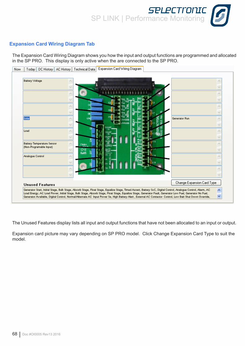
SP LINK | Performance Monitoring
68 | Doc #OI0005 Rev13 2016
Expansion Card Wiring Diagram Tab
The Expansion Card Wiring Diagram shows you how the input and output functions are programmed and allocated in the SP PRO. This display is only active when the are connected to the SP PRO.
The Unused Features display lists all input and output functions that have not been allocated to an input or output.
Expansion card picture may vary depending on SP PRO model. Click Change Expansion Card Type to suit the model.
SP LINK | Performance Monitoring
Doc #OI0005 Rev13 2016 | 69
Selectronic Australia Pty Ltd© 2016
Suite 5, 20 Fletcher RdChirnside Park VIC 3116AustraliaPh +61 3 9727 6600Fax +61 3 9727 6601
www.selectronic.com.au
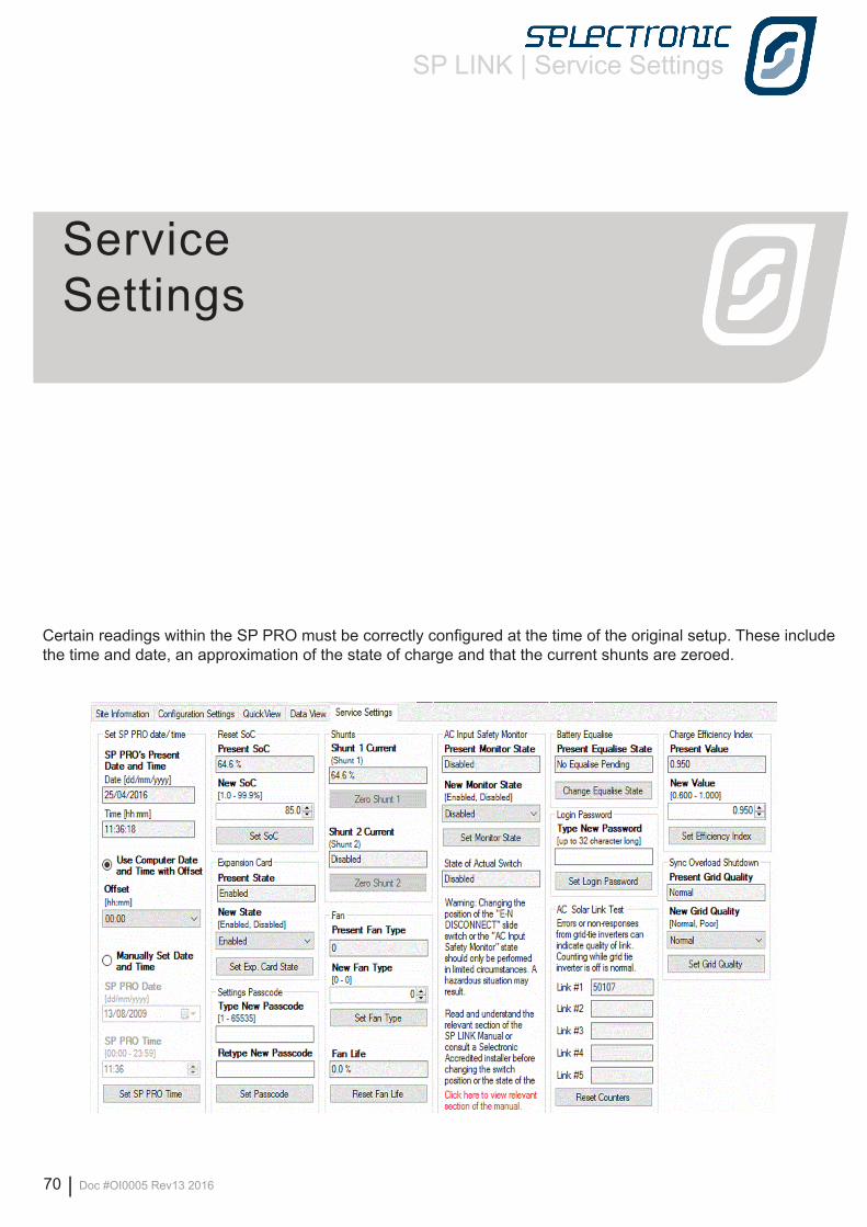
SP LINK | Service Settings
70 | Doc #OI0005 Rev13 2016
Certain readings within the SP PRO must be correctly configured at the time of the original setup. These include the time and date, an approximation of the state of charge and that the current shunts are zeroed.
Service Settings
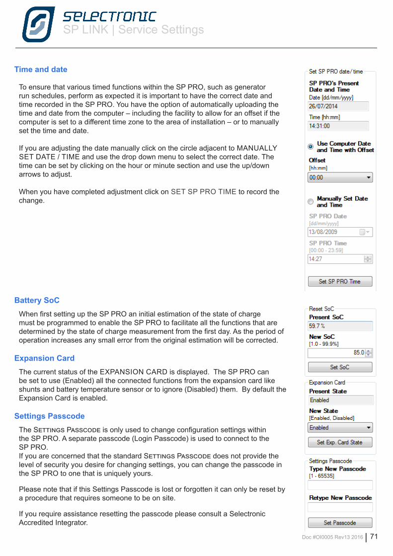
SP LINK | Service Settings
Doc #OI0005 Rev13 2016 | 71
Time and date
To ensure that various timed functions within the SP PRO, such as generator run schedules, perform as expected it is important to have the correct date and time recorded in the SP PRO. You have the option of automatically uploading the time and date from the computer – including the facility to allow for an offset if the computer is set to a different time zone to the area of installation – or to manually set the time and date.
If you are adjusting the date manually click on the circle adjacent to MANUALLY SET DATE / TIME and use the drop down menu to select the correct date. The time can be set by clicking on the hour or minute section and use the up/down arrows to adjust.
When you have completed adjustment click on SET SP PRO TIME to record the change.
Battery SoCWhen first setting up the SP PRO an initial estimation of the state of charge must be programmed to enable the SP PRO to facilitate all the functions that are determined by the state of charge measurement from the first day. As the period of operation increases any small error from the original estimation will be corrected.
Expansion CardThe current status of the EXPANSION CARD is displayed. The SP PRO can be set to use (Enabled) all the connected functions from the expansion card like shunts and battery temperature sensor or to ignore (Disabled) them. By default the Expansion Card is enabled.
Settings PasscodeThe Settings Passcode is only used to change configuration settings within the SP PRO. A separate passcode (Login Passcode) is used to connect to the SP PRO. If you are concerned that the standard Settings Passcode does not provide the level of security you desire for changing settings, you can change the passcode in the SP PRO to one that is uniquely yours.
Please note that if this Settings Passcode is lost or forgotten it can only be reset by a procedure that requires someone to be on site.
If you require assistance resetting the passcode please consult a Selectronic Accredited Integrator.
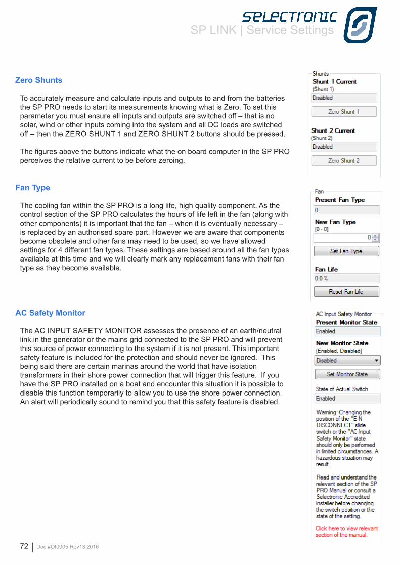
SP LINK | Service Settings
72 | Doc #OI0005 Rev13 2016
Zero Shunts
To accurately measure and calculate inputs and outputs to and from the batteries the SP PRO needs to start its measurements knowing what is Zero. To set this parameter you must ensure all inputs and outputs are switched off – that is no solar, wind or other inputs coming into the system and all DC loads are switched off – then the ZERO SHUNT 1 and ZERO SHUNT 2 buttons should be pressed.
The figures above the buttons indicate what the on board computer in the SP PRO perceives the relative current to be before zeroing.
Fan Type
The cooling fan within the SP PRO is a long life, high quality component. As the control section of the SP PRO calculates the hours of life left in the fan (along with other components) it is important that the fan – when it is eventually necessary – is replaced by an authorised spare part. However we are aware that components become obsolete and other fans may need to be used, so we have allowed settings for 4 different fan types. These settings are based around all the fan types available at this time and we will clearly mark any replacement fans with their fan type as they become available.
AC Safety Monitor
The AC INPUT SAFETY MONITOR assesses the presence of an earth/neutral link in the generator or the mains grid connected to the SP PRO and will prevent this source of power connecting to the system if it is not present. This important safety feature is included for the protection and should never be ignored. This being said there are certain marinas around the world that have isolation transformers in their shore power connection that will trigger this feature. If you have the SP PRO installed on a boat and encounter this situation it is possible to disable this function temporarily to allow you to use the shore power connection. An alert will periodically sound to remind you that this safety feature is disabled.
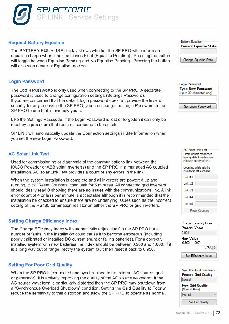
SP LINK | Service Settings
Doc #OI0005 Rev13 2016 | 73
Request Battery EqualiseThe BATTERY EQUALISE display shows whether the SP PRO will perform an equalise charge when it next achieves Float (Equalise Pending). Pressing the button will toggle between Equalise Pending and No Equalise Pending. Pressing the button will also stop a current Equalise process.
Login Password
The Login Password is only used when connecting to the SP PRO. A separate password is used to change configuration settings (Settings Password). If you are concerned that the default login password does not provide the level of security for any access to the SP PRO, you can change the Login Password in the SP PRO to one that is uniquely yours.
Like the Settings Passcode, if the Login Password is lost or forgotten it can only be reset by a procedure that requires someone to be on site.
SP LINK will automatically update the Connection settings in Site Information when you set the new Login Password.
AC Solar Link TestUsed for commissioning or diagnostic of the communications link between the KACO Powador or ABB solar inverter(s) and the SP PRO in a managed AC coupled installation. AC solar Link Test provides a count of any errors in the link.
When the system installation is complete and all inverters are powered up and running, click “Reset Counters” then wait for 5 minutes. All connected grid inverters should ideally read 0 showing there are no issues with the communications link. A link error count of 4 or less per minute is acceptable although it is recommended that the installation be checked to ensure there are no underlying issues such as the incorrect setting of the RS485 termination resistor on either the SP PRO or grid inverters.
Setting Charge Efficiency IndexThe Charge Efficiency Index will automatically adjust itself in the SP PRO but a number of faults in the installation could cause it to become erroneous (including poorly calibrated or installed DC current shunt or failing batteries). For a correctly installed system with new batteries the index should be between 0.900 and 1.000. If it is a long way out of range, rectify the system fault then reset it back to 0.950.
Setting For Poor Grid QualityWhen the SP PRO is connected and synchronised to an external AC source (grid or generator), it is actively improving the quality of the AC source waveform. If the AC source waveform is particularly distorted then the SP PRO may shutdown from a “Synchronous Overload Shutdown” condition. Setting the Grid Quality to Poor will reduce the sensitivity to this distortion and allow the SP PRO to operate as normal.
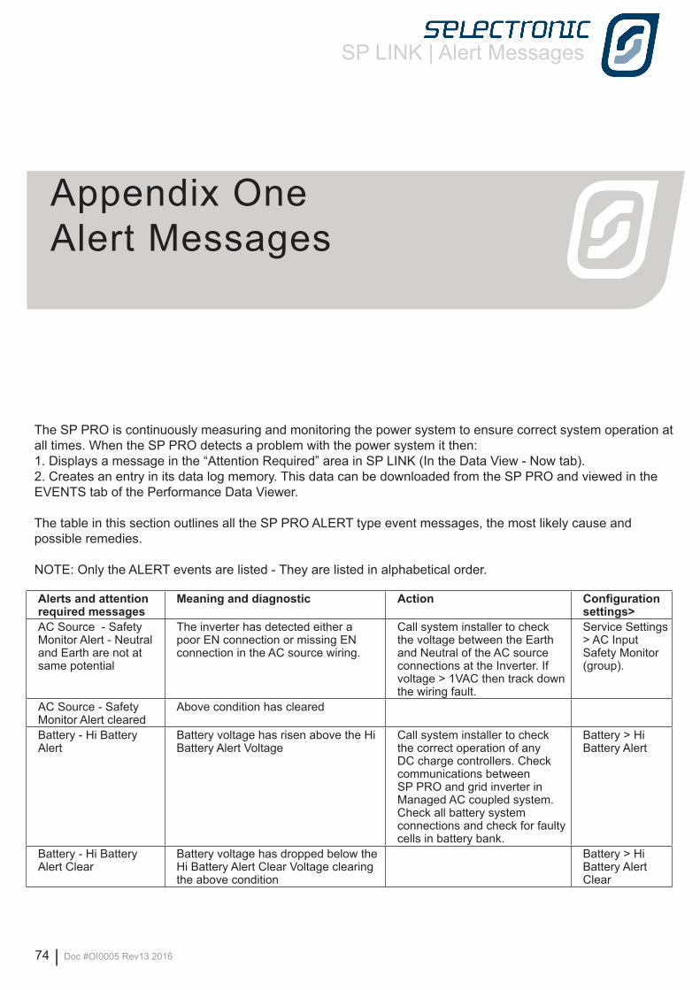
SP LINK | Alert Messages
74 | Doc #OI0005 Rev13 2016
Appendix One Alert Messages
The SP PRO is continuously measuring and monitoring the power system to ensure correct system operation at all times. When the SP PRO detects a problem with the power system it then:1. Displays a message in the “Attention Required” area in SP LINK (In the Data View - Now tab).2. Creates an entry in its data log memory. This data can be downloaded from the SP PRO and viewed in the EVENTS tab of the Performance Data Viewer.
The table in this section outlines all the SP PRO ALERT type event messages, the most likely cause and possible remedies.
NOTE: Only the ALERT events are listed - They are listed in alphabetical order.
Alerts and attention required messages
Meaning and diagnostic Action Configuration settings>
AC Source - Safety Monitor Alert - Neutral and Earth are not at same potential
The inverter has detected either a poor EN connection or missing EN connection in the AC source wiring.
Call system installer to check the voltage between the Earth and Neutral of the AC source connections at the Inverter. If voltage > 1VAC then track down the wiring fault.
Service Settings > AC Input Safety Monitor (group).
AC Source - Safety Monitor Alert cleared
Above condition has cleared
Battery - Hi Battery Alert
Battery voltage has risen above the Hi Battery Alert Voltage
Call system installer to check the correct operation of any DC charge controllers. Check communications between SP PRO and grid inverter in Managed AC coupled system. Check all battery system connections and check for faulty cells in battery bank.
Battery > Hi Battery Alert
Battery - Hi Battery Alert Clear
Battery voltage has dropped below the Hi Battery Alert Clear Voltage clearing the above condition
Battery > Hi Battery Alert Clear
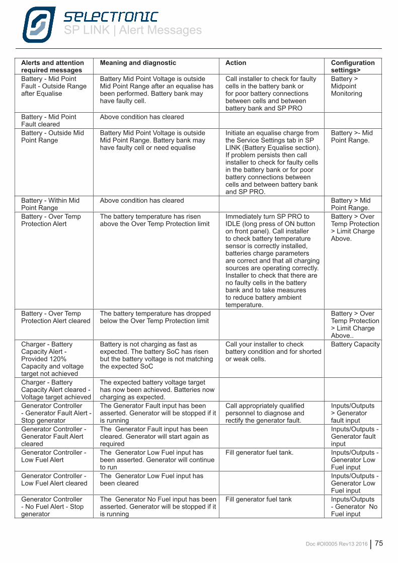
SP LINK | Alert Messages
Doc #OI0005 Rev13 2016 | 75
Alerts and attention required messages
Meaning and diagnostic Action Configuration settings>
Battery - Mid Point Fault - Outside Range after Equalise
Battery Mid Point Voltage is outside Mid Point Range after an equalise has been performed. Battery bank may have faulty cell.
Call installer to check for faulty cells in the battery bank or for poor battery connections between cells and between battery bank and SP PRO
Battery > Midpoint Monitoring
Battery - Mid Point Fault cleared
Above condition has cleared
Battery - Outside Mid Point Range
Battery Mid Point Voltage is outside Mid Point Range. Battery bank may have faulty cell or need equalise
Initiate an equalise charge from the Service Settings tab in SP LINK (Battery Equalise section). If problem persists then call installer to check for faulty cells in the battery bank or for poor battery connections between cells and between battery bank and SP PRO.
Battery >- Mid Point Range.
Battery - Within Mid Point Range
Above condition has cleared Battery > Mid Point Range.
Battery - Over Temp Protection Alert
The battery temperature has risen above the Over Temp Protection limit
Immediately turn SP PRO to IDLE (long press of ON button on front panel). Call installer to check battery temperature sensor is correctly installed, batteries charge parameters are correct and that all charging sources are operating correctly. Installer to check that there are no faulty cells in the battery bank and to take measures to reduce battery ambient temperature.
Battery > Over Temp Protection > Limit Charge Above.
Battery - Over Temp Protection Alert cleared
The battery temperature has dropped below the Over Temp Protection limit
Battery > Over Temp Protection > Limit Charge Above..
Charger - Battery Capacity Alert - Provided 120% Capacity and voltage target not achieved
Battery is not charging as fast as expected. The battery SoC has risen but the battery voltage is not matching the expected SoC
Call your installer to check battery condition and for shorted or weak cells.
Battery Capacity
Charger - Battery Capacity Alert cleared - Voltage target achieved
The expected battery voltage target has now been achieved. Batteries now charging as expected.
Generator Controller - Generator Fault Alert - Stop generator
The Generator Fault input has been asserted. Generator will be stopped if it is running
Call appropriately qualified personnel to diagnose and rectify the generator fault.
Inputs/Outputs > Generator fault input
Generator Controller - Generator Fault Alert cleared
The Generator Fault input has been cleared. Generator will start again as required
Inputs/Outputs - Generator fault input
Generator Controller - Low Fuel Alert
The Generator Low Fuel input has been asserted. Generator will continue to run
Fill generator fuel tank. Inputs/Outputs - Generator Low Fuel input
Generator Controller - Low Fuel Alert cleared
The Generator Low Fuel input has been cleared
Inputs/Outputs - Generator Low Fuel input
Generator Controller - No Fuel Alert - Stop generator
The Generator No Fuel input has been asserted. Generator will be stopped if it is running
Fill generator fuel tank Inputs/Outputs - Generator No Fuel input
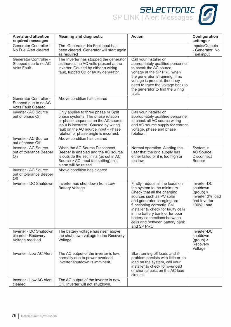
SP LINK | Alert Messages
76 | Doc #OI0005 Rev13 2016
Alerts and attention required messages
Meaning and diagnostic Action Configuration settings>
Generator Controller - No Fuel Alert cleared
The Generator No Fuel input has been cleared. Generator will start again as required
Inputs/Outputs - Generator No Fuel input
Generator Controller - Stopped due to no AC Volts Fault
The Inverter has stopped the generator as there is no AC volts present at the inverter. Caused by either a wiring fault, tripped CB or faulty generator.
Call your installer or appropriately qualified personnel to check the AC source voltage at the SP PRO when the generator is running. If no voltage is present, then they need to trace the voltage back to the generator to find the wiring fault.
Generator Controller - Stopped due to no AC Volts Fault Cleared
Above condition has cleared
Inverter - AC Source out of phase On
Only applies to three phase or Split phase systems. The phase rotation or phase sequence on the AC source input is incorrect. Caused by wiring fault on the AC source input - Phase rotation or phase angle is incorrect.
Call your installer or appropriately qualified personnel to check all AC source wiring and AC source supply for correct voltage, phase and phase rotation.
Inverter - AC Source out of phase Off
Above condition has cleared
Inverter - AC Source out of tolerance Beeper On
When the AC Source Disconnect Beeper is enabled and the AC source is outside the set limits (as set in AC Source > AC Input tab setting) this alarm will be raised
Normal operation. Alerting the user that the grid supply has either failed or it is too high or too low.
System > AC Source Disconnect Beeper
Inverter - AC Source out of tolerance Beeper Off
Above condition has cleared
Inverter - DC Shutdown Inverter has shut down from Low Battery Voltage
Firstly, reduce all the loads on the system to the minimum. Check that all the charging sources such as PV solar and generator charging are functioning correctly. Call installer to check for faulty cells in the battery bank or for poor battery connections between cells and between battery bank and SP PRO
Inverter-DC shutdown (group) > Inverter 0% load and Inverter 100% Load
Inverter - DC Shutdown cleared - Recovery Voltage reached
The battery voltage has risen above the shut down voltage to the Recovery Voltage
Inverter-DC shutdown (group) > Recovery Voltage
Inverter - Low AC Alert The AC output of the inverter is low, normally due to power overload. Inverter shutdown is imminent.
Start turning off loads and if problem persists with little or no load on the system, call your installer to check for overload or short circuits on the AC load circuits.
Inverter - Low AC Alert cleared
The AC output of the inverter is now OK. Inverter will not shutdown.
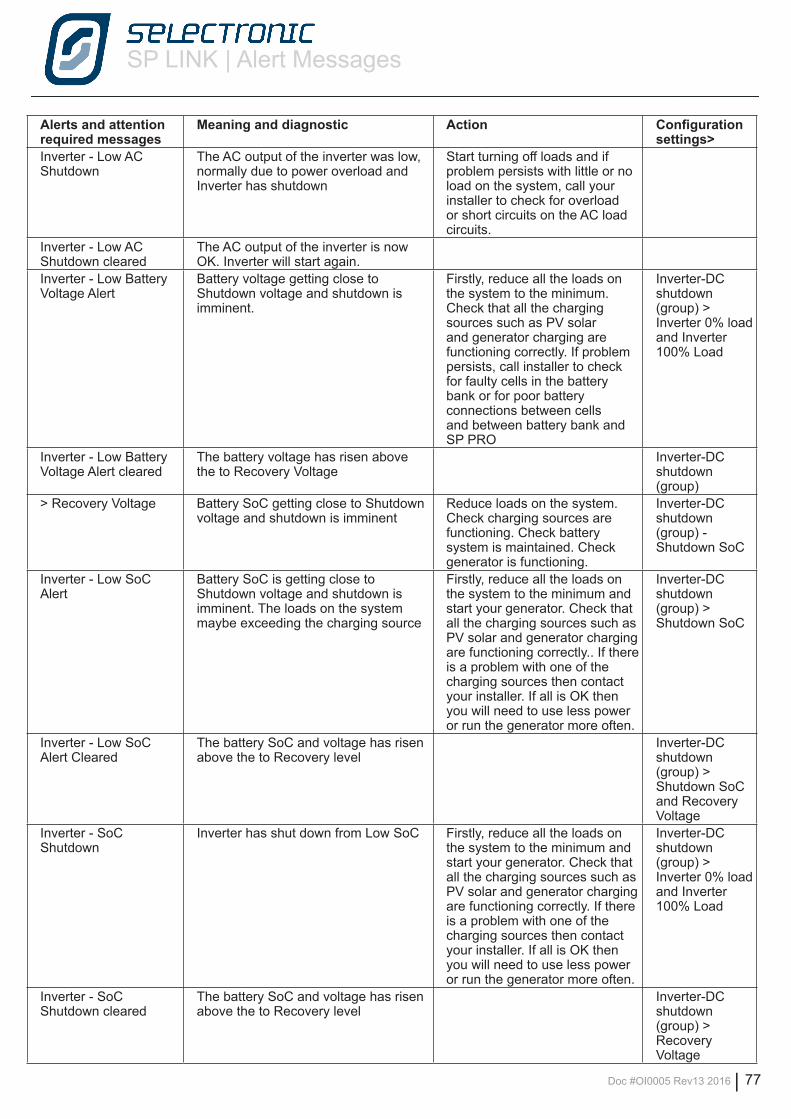
SP LINK | Alert Messages
Doc #OI0005 Rev13 2016 | 77
Alerts and attention required messages
Meaning and diagnostic Action Configuration settings>
Inverter - Low AC Shutdown
The AC output of the inverter was low, normally due to power overload and Inverter has shutdown
Start turning off loads and if problem persists with little or no load on the system, call your installer to check for overload or short circuits on the AC load circuits.
Inverter - Low AC Shutdown cleared
The AC output of the inverter is now OK. Inverter will start again.
Inverter - Low Battery Voltage Alert
Battery voltage getting close to Shutdown voltage and shutdown is imminent.
Firstly, reduce all the loads on the system to the minimum. Check that all the charging sources such as PV solar and generator charging are functioning correctly. If problem persists, call installer to check for faulty cells in the battery bank or for poor battery connections between cells and between battery bank and SP PRO
Inverter-DC shutdown (group) > Inverter 0% load and Inverter 100% Load
Inverter - Low Battery Voltage Alert cleared
The battery voltage has risen above the to Recovery Voltage
Inverter-DC shutdown (group)
> Recovery Voltage Battery SoC getting close to Shutdown voltage and shutdown is imminent
Reduce loads on the system. Check charging sources are functioning. Check battery system is maintained. Check generator is functioning.
Inverter-DC shutdown (group) - Shutdown SoC
Inverter - Low SoC Alert
Battery SoC is getting close to Shutdown voltage and shutdown is imminent. The loads on the system maybe exceeding the charging source
Firstly, reduce all the loads on the system to the minimum and start your generator. Check that all the charging sources such as PV solar and generator charging are functioning correctly.. If there is a problem with one of the charging sources then contact your installer. If all is OK then you will need to use less power or run the generator more often.
Inverter-DC shutdown (group) > Shutdown SoC
Inverter - Low SoC Alert Cleared
The battery SoC and voltage has risen above the to Recovery level
Inverter-DC shutdown (group) > Shutdown SoC and Recovery Voltage
Inverter - SoC Shutdown
Inverter has shut down from Low SoC Firstly, reduce all the loads on the system to the minimum and start your generator. Check that all the charging sources such as PV solar and generator charging are functioning correctly. If there is a problem with one of the charging sources then contact your installer. If all is OK then you will need to use less power or run the generator more often.
Inverter-DC shutdown (group) > Inverter 0% load and Inverter 100% Load
Inverter - SoC Shutdown cleared
The battery SoC and voltage has risen above the to Recovery level
Inverter-DC shutdown (group) > Recovery Voltage
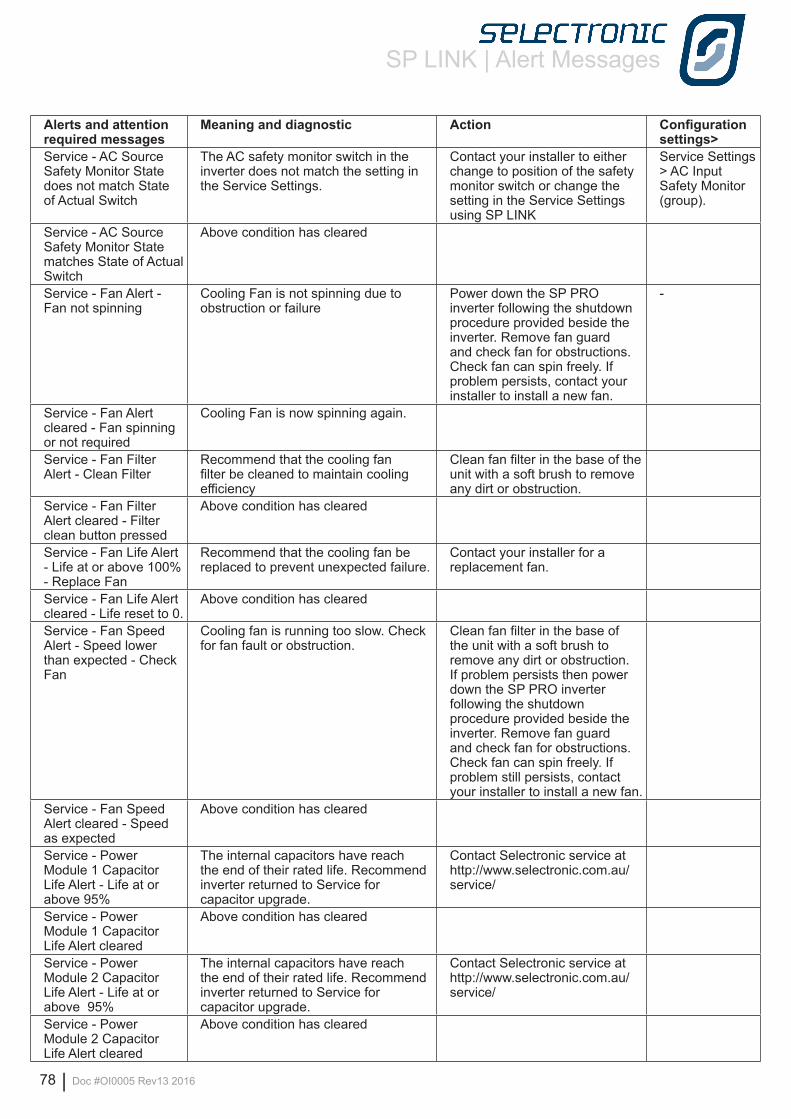
SP LINK | Alert Messages
78 | Doc #OI0005 Rev13 2016
Alerts and attention required messages
Meaning and diagnostic Action Configuration settings>
Service - AC Source Safety Monitor State does not match State of Actual Switch
The AC safety monitor switch in the inverter does not match the setting in the Service Settings.
Contact your installer to either change to position of the safety monitor switch or change the setting in the Service Settings using SP LINK
Service Settings > AC Input Safety Monitor (group).
Service - AC Source Safety Monitor State matches State of Actual Switch
Above condition has cleared
Service - Fan Alert - Fan not spinning
Cooling Fan is not spinning due to obstruction or failure
Power down the SP PRO inverter following the shutdown procedure provided beside the inverter. Remove fan guard and check fan for obstructions. Check fan can spin freely. If problem persists, contact your installer to install a new fan.
-
Service - Fan Alert cleared - Fan spinning or not required
Cooling Fan is now spinning again.
Service - Fan Filter Alert - Clean Filter
Recommend that the cooling fan filter be cleaned to maintain cooling efficiency
Clean fan filter in the base of the unit with a soft brush to remove any dirt or obstruction.
Service - Fan Filter Alert cleared - Filter clean button pressed
Above condition has cleared
Service - Fan Life Alert - Life at or above 100% - Replace Fan
Recommend that the cooling fan be replaced to prevent unexpected failure.
Contact your installer for a replacement fan.
Service - Fan Life Alert cleared - Life reset to 0.
Above condition has cleared
Service - Fan Speed Alert - Speed lower than expected - Check Fan
Cooling fan is running too slow. Check for fan fault or obstruction.
Clean fan filter in the base of the unit with a soft brush to remove any dirt or obstruction. If problem persists then power down the SP PRO inverter following the shutdown procedure provided beside the inverter. Remove fan guard and check fan for obstructions. Check fan can spin freely. If problem still persists, contact your installer to install a new fan.
Service - Fan Speed Alert cleared - Speed as expected
Above condition has cleared
Service - Power Module 1 Capacitor Life Alert - Life at or above 95%
The internal capacitors have reach the end of their rated life. Recommend inverter returned to Service for capacitor upgrade.
Contact Selectronic service at http://www.selectronic.com.au/service/
Service - Power Module 1 Capacitor Life Alert cleared
Above condition has cleared
Service - Power Module 2 Capacitor Life Alert - Life at or above 95%
The internal capacitors have reach the end of their rated life. Recommend inverter returned to Service for capacitor upgrade.
Contact Selectronic service at http://www.selectronic.com.au/service/
Service - Power Module 2 Capacitor Life Alert cleared
Above condition has cleared
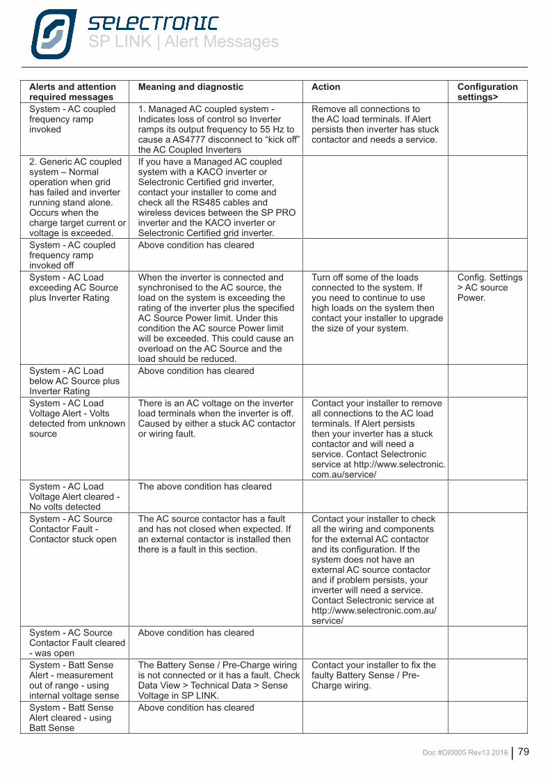
SP LINK | Alert Messages
Doc #OI0005 Rev13 2016 | 79
Alerts and attention required messages
Meaning and diagnostic Action Configuration settings>
System - AC coupled frequency ramp invoked
1. Managed AC coupled system - Indicates loss of control so Inverter ramps its output frequency to 55 Hz to cause a AS4777 disconnect to “kick off” the AC Coupled Inverters
Remove all connections to the AC load terminals. If Alert persists then inverter has stuck contactor and needs a service.
2. Generic AC coupled system – Normal operation when grid has failed and inverter running stand alone. Occurs when the charge target current or voltage is exceeded.
If you have a Managed AC coupled system with a KACO inverter or Selectronic Certified grid inverter, contact your installer to come and check all the RS485 cables and wireless devices between the SP PRO inverter and the KACO inverter or Selectronic Certified grid inverter.
System - AC coupled frequency ramp invoked off
Above condition has cleared
System - AC Load exceeding AC Source plus Inverter Rating
When the inverter is connected and synchronised to the AC source, the load on the system is exceeding the rating of the inverter plus the specified AC Source Power limit. Under this condition the AC source Power limit will be exceeded. This could cause an overload on the AC Source and the load should be reduced.
Turn off some of the loads connected to the system. If you need to continue to use high loads on the system then contact your installer to upgrade the size of your system.
Config. Settings > AC source Power.
System - AC Load below AC Source plus Inverter Rating
Above condition has cleared
System - AC Load Voltage Alert - Volts detected from unknown source
There is an AC voltage on the inverter load terminals when the inverter is off. Caused by either a stuck AC contactor or wiring fault.
Contact your installer to remove all connections to the AC load terminals. If Alert persists then your inverter has a stuck contactor and will need a service. Contact Selectronic service at http://www.selectronic.com.au/service/
System - AC Load Voltage Alert cleared - No volts detected
The above condition has cleared
System - AC Source Contactor Fault - Contactor stuck open
The AC source contactor has a fault and has not closed when expected. If an external contactor is installed then there is a fault in this section.
Contact your installer to check all the wiring and components for the external AC contactor and its configuration. If the system does not have an external AC source contactor and if problem persists, your inverter will need a service. Contact Selectronic service at http://www.selectronic.com.au/service/
System - AC Source Contactor Fault cleared - was open
Above condition has cleared
System - Batt Sense Alert - measurement out of range - using internal voltage sense
The Battery Sense / Pre-Charge wiring is not connected or it has a fault. Check Data View > Technical Data > Sense Voltage in SP LINK.
Contact your installer to fix the faulty Battery Sense / Pre-Charge wiring.
System - Batt Sense Alert cleared - using Batt Sense
Above condition has cleared
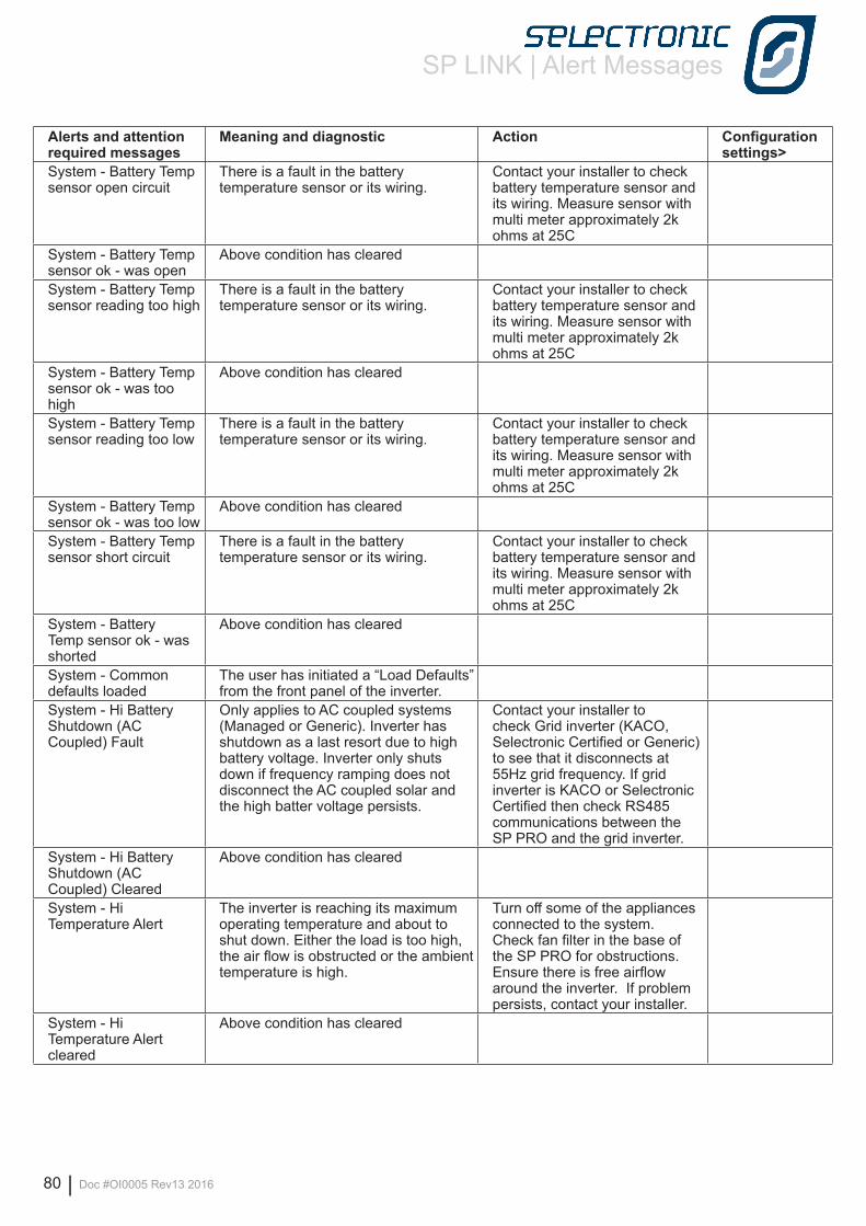
SP LINK | Alert Messages
80 | Doc #OI0005 Rev13 2016
Alerts and attention required messages
Meaning and diagnostic Action Configuration settings>
System - Battery Temp sensor open circuit
There is a fault in the battery temperature sensor or its wiring.
Contact your installer to check battery temperature sensor and its wiring. Measure sensor with multi meter approximately 2k ohms at 25C
System - Battery Temp sensor ok - was open
Above condition has cleared
System - Battery Temp sensor reading too high
There is a fault in the battery temperature sensor or its wiring.
Contact your installer to check battery temperature sensor and its wiring. Measure sensor with multi meter approximately 2k ohms at 25C
System - Battery Temp sensor ok - was too high
Above condition has cleared
System - Battery Temp sensor reading too low
There is a fault in the battery temperature sensor or its wiring.
Contact your installer to check battery temperature sensor and its wiring. Measure sensor with multi meter approximately 2k ohms at 25C
System - Battery Temp sensor ok - was too low
Above condition has cleared
System - Battery Temp sensor short circuit
There is a fault in the battery temperature sensor or its wiring.
Contact your installer to check battery temperature sensor and its wiring. Measure sensor with multi meter approximately 2k ohms at 25C
System - Battery Temp sensor ok - was shorted
Above condition has cleared
System - Common defaults loaded
The user has initiated a “Load Defaults” from the front panel of the inverter.
System - Hi Battery Shutdown (AC Coupled) Fault
Only applies to AC coupled systems (Managed or Generic). Inverter has shutdown as a last resort due to high battery voltage. Inverter only shuts down if frequency ramping does not disconnect the AC coupled solar and the high batter voltage persists.
Contact your installer to check Grid inverter (KACO, Selectronic Certified or Generic) to see that it disconnects at 55Hz grid frequency. If grid inverter is KACO or Selectronic Certified then check RS485 communications between the SP PRO and the grid inverter.
System - Hi Battery Shutdown (AC Coupled) Cleared
Above condition has cleared
System - Hi Temperature Alert
The inverter is reaching its maximum operating temperature and about to shut down. Either the load is too high, the air flow is obstructed or the ambient temperature is high.
Turn off some of the appliances connected to the system. Check fan filter in the base of the SP PRO for obstructions. Ensure there is free airflow around the inverter. If problem persists, contact your installer.
System - Hi Temperature Alert cleared
Above condition has cleared
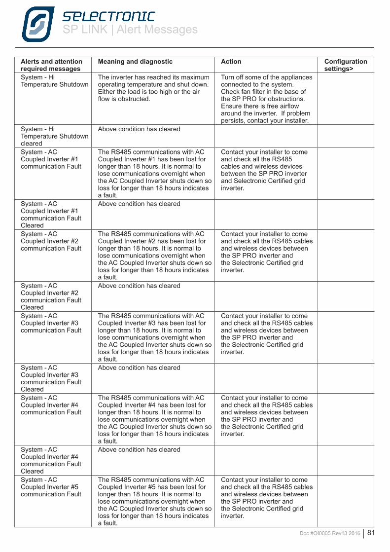
SP LINK | Alert Messages
Doc #OI0005 Rev13 2016 | 81
Alerts and attention required messages
Meaning and diagnostic Action Configuration settings>
System - Hi Temperature Shutdown
The inverter has reached its maximum operating temperature and shut down. Either the load is too high or the air flow is obstructed.
Turn off some of the appliances connected to the system. Check fan filter in the base of the SP PRO for obstructions. Ensure there is free airflow around the inverter. If problem persists, contact your installer.
System - Hi Temperature Shutdown cleared
Above condition has cleared
System - AC Coupled Inverter #1 communication Fault
The RS485 communications with AC Coupled Inverter #1 has been lost for longer than 18 hours. It is normal to lose communications overnight when the AC Coupled Inverter shuts down so loss for longer than 18 hours indicates a fault.
Contact your installer to come and check all the RS485 cables and wireless devices between the SP PRO inverter and Selectronic Certified grid inverter.
System - AC Coupled Inverter #1 communication Fault Cleared
Above condition has cleared
System - AC Coupled Inverter #2 communication Fault
The RS485 communications with AC Coupled Inverter #2 has been lost for longer than 18 hours. It is normal to lose communications overnight when the AC Coupled Inverter shuts down so loss for longer than 18 hours indicates a fault.
Contact your installer to come and check all the RS485 cables and wireless devices between the SP PRO inverter and the Selectronic Certified grid inverter.
System - AC Coupled Inverter #2 communication Fault Cleared
Above condition has cleared
System - AC Coupled Inverter #3 communication Fault
The RS485 communications with AC Coupled Inverter #3 has been lost for longer than 18 hours. It is normal to lose communications overnight when the AC Coupled Inverter shuts down so loss for longer than 18 hours indicates a fault.
Contact your installer to come and check all the RS485 cables and wireless devices between the SP PRO inverter and the Selectronic Certified grid inverter.
System - AC Coupled Inverter #3 communication Fault Cleared
Above condition has cleared
System - AC Coupled Inverter #4 communication Fault
The RS485 communications with AC Coupled Inverter #4 has been lost for longer than 18 hours. It is normal to lose communications overnight when the AC Coupled Inverter shuts down so loss for longer than 18 hours indicates a fault.
Contact your installer to come and check all the RS485 cables and wireless devices between the SP PRO inverter and the Selectronic Certified grid inverter.
System - AC Coupled Inverter #4 communication Fault Cleared
Above condition has cleared
System - AC Coupled Inverter #5 communication Fault
The RS485 communications with AC Coupled Inverter #5 has been lost for longer than 18 hours. It is normal to lose communications overnight when the AC Coupled Inverter shuts down so loss for longer than 18 hours indicates a fault.
Contact your installer to come and check all the RS485 cables and wireless devices between the SP PRO inverter and the Selectronic Certified grid inverter.
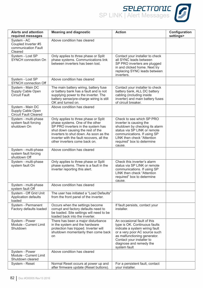
SP LINK | Alert Messages
82 | Doc #OI0005 Rev13 2016
Alerts and attention required messages
Meaning and diagnostic Action Configuration settings>
System - AC Coupled Inverter #5 communication Fault Cleared
Above condition has cleared
System - Lost SP SYNCH connection On
Only applies to three phase or Split phase systems. Communications link between inverters has been lost.
Contact your installer to check all SYNC leads between SP PRO inverters are plugged in and clicked home. Next try replacing SYNC leads between inverters.
System - Lost SP SYNCH connection Off
Above condition has cleared
System - Main DC Supply Cable Open Circuit Fault
The main battery wiring, battery fuse or battery bank has a fault and is not supplying power to the inverter. The battery sense/pre-charge wiring is still OK and turned on.
Contact your installer to check battery bank, ALL DC battery cabling (including inside inverter) and main battery fuses of circuit breaker.
System - Main DC Supply Cable Open Circuit Fault Cleared
Above condition has cleared
System - multi-phase system fault forcing shutdown On
Only applies to three phase or Split phase systems. One of the other SP PRO inverters in the system has shut down causing the rest of the inverters to shut down. As soon as the inverter with the fault recovers, all the other inverters come back on.
Check to see which SP PRO inverter is causing the shutdown by checking its alarm status via SP LINK or remote communications. If using SP LINK then check “Attention required” box to determine cause.
System - multi-phase system fault forcing shutdown Off
Above condition has cleared
System - multi-phase system fault On
Only applies to three phase or Split phase systems. There is a fault in the inverter reporting this alert.
Check this inverter’s alarm status via SP LINK or remote communications. If using SP LINK then check “Attention required” box to determine cause.
System - multi-phase system fault Off
Above condition has cleared
System - Off Grid Unit Application defaults loaded
The user has initiated a “Load Defaults” from the front panel of the inverter.
System - Permanent Factory defaults loaded
Occurs when the settings become corrupt and factory defaults need to be loaded. Site settings will need to be loaded back into the inverter.
If fault persists, contact your installer.
System - Power Module - Current Limit Shutdown
There has been a major disturbance in the system and the hardware protection has tripped. Inverter will shutdown momentarily then come back on
An occasional fault of this type is OK. Continuous faults indicate a system wiring fault or a very poor AC source such as malfunctioning generator. Contact your installer to diagnose and remedy the system fault
System - Power Module - Current Limit Shutdown cleared
Above condition has cleared
System - Reset Normal Reset occurs at power up and after firmware update (Reset buttons).
For a persistent fault, contact your installer.
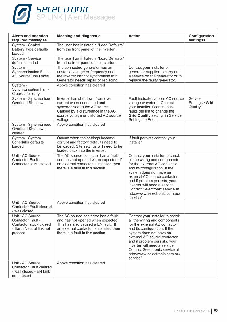
SP LINK | Alert Messages
Doc #OI0005 Rev13 2016 | 83
Alerts and attention required messages
Meaning and diagnostic Action Configuration settings>
System - Sealed Battery Type defaults loaded
The user has initiated a “Load Defaults” from the front panel of the inverter.
System - Service defaults loaded
The user has initiated a “Load Defaults” from the front panel of the inverter.
System - Synchronisation Fail - AC Source unsuitable
The connected generator has an unstable voltage or frequency and the inverter cannot synchronise to it. Generator needs repair or replacing.
Contact your installer or generator supplier to carry out a service on the generator or to replace the faulty generator.
System - Synchronisation Fail - Cleared for retry
Above condition has cleared
System - Synchronised Overload Shutdown
Inverter has shutdown from over current when connected and synchronised to the AC source. Caused by a disturbance in the AC source voltage or distorted AC source voltage.
Fault indicates a poor AC source voltage waveform. Contact your installer if continuous faults persist to change the Grid Quality setting in Service Settings to Poor.
Service Settings> Grid Quality
System - Synchronised Overload Shutdown cleared
Above condition has cleared
System - System Scheduler defaults loaded
Occurs when the settings become corrupt and factory defaults need to be loaded. Site settings will need to be loaded back into the inverter.
If fault persists contact your installer.
Unit - AC Source Contactor Fault - Contactor stuck closed
The AC source contactor has a fault and has not opened when expected. If an external contactor is installed then there is a fault in this section.
Contact your installer to check all the wiring and components for the external AC contactor and its configuration. If the system does not have an external AC source contactor and if problem persists, your inverter will need a service. Contact Selectronic service at http://www.selectronic.com.au/service/
Unit - AC Source Contactor Fault cleared - was closed
Above condition has cleared
Unit - AC Source Contactor Fault - Contactor stuck closed - Earth Neutral link not present
The AC source contactor has a fault and has not opened when expected. This has also caused a EN fault. If an external contactor is installed then there is a fault in this section.
Contact your installer to check all the wiring and components for the external AC contactor and its configuration. If the system does not have an external AC source contactor and if problem persists, your inverter will need a service. Contact Selectronic service at http://www.selectronic.com.au/service/
Unit - AC Source Contactor Fault cleared - was closed - EN Link not present
Above condition has cleared
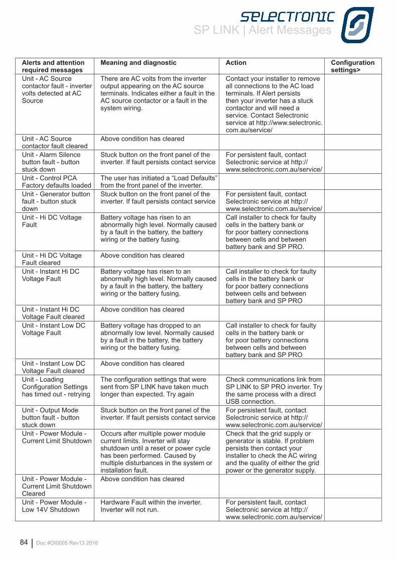
SP LINK | Alert Messages
84 | Doc #OI0005 Rev13 2016
Alerts and attention required messages
Meaning and diagnostic Action Configuration settings>
Unit - AC Source contactor fault - inverter volts detected at AC Source
There are AC volts from the inverter output appearing on the AC source terminals. Indicates either a fault in the AC source contactor or a fault in the system wiring.
Contact your installer to remove all connections to the AC load terminals. If Alert persists then your inverter has a stuck contactor and will need a service. Contact Selectronic service at http://www.selectronic.com.au/service/
Unit - AC Source contactor fault cleared
Above condition has cleared
Unit - Alarm Silence button fault - button stuck down
Stuck button on the front panel of the inverter. If fault persists contact service
For persistent fault, contact Selectronic service at http://www.selectronic.com.au/service/
Unit - Control PCA Factory defaults loaded
The user has initiated a “Load Defaults” from the front panel of the inverter.
Unit - Generator button fault - button stuck down
Stuck button on the front panel of the inverter. If fault persists contact service
For persistent fault, contact Selectronic service at http://www.selectronic.com.au/service/
Unit - Hi DC Voltage Fault
Battery voltage has risen to an abnormally high level. Normally caused by a fault in the battery, the battery wiring or the battery fusing.
Call installer to check for faulty cells in the battery bank or for poor battery connections between cells and between battery bank and SP PRO.
Unit - Hi DC Voltage Fault cleared
Above condition has cleared
Unit - Instant Hi DC Voltage Fault
Battery voltage has risen to an abnormally high level. Normally caused by a fault in the battery, the battery wiring or the battery fusing.
Call installer to check for faulty cells in the battery bank or for poor battery connections between cells and between battery bank and SP PRO
Unit - Instant Hi DC Voltage Fault cleared
Above condition has cleared
Unit - Instant Low DC Voltage Fault
Battery voltage has dropped to an abnormally low level. Normally caused by a fault in the battery, the battery wiring or the battery fusing.
Call installer to check for faulty cells in the battery bank or for poor battery connections between cells and between battery bank and SP PRO
Unit - Instant Low DC Voltage Fault cleared
Above condition has cleared
Unit - Loading Configuration Settings has timed out - retrying
The configuration settings that were sent from SP LINK have taken much longer than expected. Try again
Check communications link from SP LINK to SP PRO inverter. Try the same process with a direct USB connection.
Unit - Output Mode button fault - button stuck down
Stuck button on the front panel of the inverter. If fault persists contact service
For persistent fault, contact Selectronic service at http://www.selectronic.com.au/service/
Unit - Power Module - Current Limit Shutdown
Occurs after multiple power module current limits. Inverter will stay shutdown until a reset or power cycle has been performed. Caused by multiple disturbances in the system or installation fault.
Check that the grid supply or generator is stable. If problem persists then contact your installer to check the AC wiring and the quality of either the grid power or the generator supply.
Unit - Power Module - Current Limit Shutdown Cleared
Above condition has cleared
Unit - Power Module - Low 14V Shutdown
Hardware Fault within the inverter. Inverter will not run.
For persistent fault, contact Selectronic service at http://www.selectronic.com.au/service/
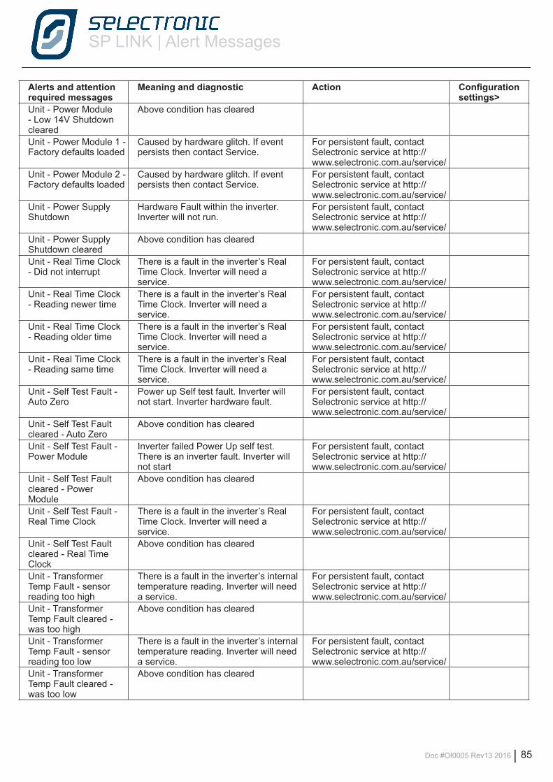
SP LINK | Alert Messages
Doc #OI0005 Rev13 2016 | 85
Alerts and attention required messages
Meaning and diagnostic Action Configuration settings>
Unit - Power Module - Low 14V Shutdown cleared
Above condition has cleared
Unit - Power Module 1 - Factory defaults loaded
Caused by hardware glitch. If event persists then contact Service.
For persistent fault, contact Selectronic service at http://www.selectronic.com.au/service/
Unit - Power Module 2 - Factory defaults loaded
Caused by hardware glitch. If event persists then contact Service.
For persistent fault, contact Selectronic service at http://www.selectronic.com.au/service/
Unit - Power Supply Shutdown
Hardware Fault within the inverter. Inverter will not run.
For persistent fault, contact Selectronic service at http://www.selectronic.com.au/service/
Unit - Power Supply Shutdown cleared
Above condition has cleared
Unit - Real Time Clock - Did not interrupt
There is a fault in the inverter’s Real Time Clock. Inverter will need a service.
For persistent fault, contact Selectronic service at http://www.selectronic.com.au/service/
Unit - Real Time Clock - Reading newer time
There is a fault in the inverter’s Real Time Clock. Inverter will need a service.
For persistent fault, contact Selectronic service at http://www.selectronic.com.au/service/
Unit - Real Time Clock - Reading older time
There is a fault in the inverter’s Real Time Clock. Inverter will need a service.
For persistent fault, contact Selectronic service at http://www.selectronic.com.au/service/
Unit - Real Time Clock - Reading same time
There is a fault in the inverter’s Real Time Clock. Inverter will need a service.
For persistent fault, contact Selectronic service at http://www.selectronic.com.au/service/
Unit - Self Test Fault - Auto Zero
Power up Self test fault. Inverter will not start. Inverter hardware fault.
For persistent fault, contact Selectronic service at http://www.selectronic.com.au/service/
Unit - Self Test Fault cleared - Auto Zero
Above condition has cleared
Unit - Self Test Fault - Power Module
Inverter failed Power Up self test. There is an inverter fault. Inverter will not start
For persistent fault, contact Selectronic service at http://www.selectronic.com.au/service/
Unit - Self Test Fault cleared - Power Module
Above condition has cleared
Unit - Self Test Fault - Real Time Clock
There is a fault in the inverter’s Real Time Clock. Inverter will need a service.
For persistent fault, contact Selectronic service at http://www.selectronic.com.au/service/
Unit - Self Test Fault cleared - Real Time Clock
Above condition has cleared
Unit - Transformer Temp Fault - sensor reading too high
There is a fault in the inverter’s internal temperature reading. Inverter will need a service.
For persistent fault, contact Selectronic service at http://www.selectronic.com.au/service/
Unit - Transformer Temp Fault cleared - was too high
Above condition has cleared
Unit - Transformer Temp Fault - sensor reading too low
There is a fault in the inverter’s internal temperature reading. Inverter will need a service.
For persistent fault, contact Selectronic service at http://www.selectronic.com.au/service/
Unit - Transformer Temp Fault cleared - was too low
Above condition has cleared

Selectronic Australia Pty Ltd© 2016
Suite 5, 20 Fletcher RdChirnside Park VIC 3116AustraliaPh +61 3 9727 6600Fax +61 3 9727 6601
www.selectronic.com.au