instruction manual - hobbicomanuals.hobbico.com/fut/6da-manual.pdf · instruction manual thank you...
TRANSCRIPT

Instruction ManualThank you for purchasing the Futaba 6DA 6-channel with Flight Set radio system. Whether this is your firstR/C radio system, or you’re moving up or replacing a trusted old friend, we believe you’ll be pleased withyour 6DA. Futaba is the leader in R/C radio technology. Please read this instruction manual carefully and use the 6DA radio system safely. If you are unfamiliar withsome of the terms in this instruction manual, take a few minutes to read the glossary. It contains usefulinformation about terms that will help you understand the functions and features of this radio. Save thismanual for future reference and, most of all, have fun!
Entire Contents © Copyright 2001 FUTZ8570 V1.0
Safety Information ......................2
Features & Specifications ............6
Battery Care ................................7
Installing Servos ..........................7
Setting Up Your Radio Gear ........8
Transmitter Operation ...............10
Servo Reversing .........................11
Throttle EPA ..............................12
AST's .........................................13
Dual Rates.................................14
Aileron-to-Rudder Mixing .........15
Dual Aileron Servos/Flaperons ..16
Aileron Differential ...................17
Retractable Landing Gear..........18
Flaps ..........................................19
Flap-to-Elevator Mixing .............19
Trainer Function ........................20
Prepare to Fly............................20
Glossary ....................................21
Troubleshooting Guide ..............23
Radio System
•No part of this manual may be reproduced in any form without prior permission.•The contents of this manual are subject to change without prior notice.•This manual has been carefully written. Please write to Futaba if you feel that any corrections or clarifications should be made.•Futaba is not responsible for the misuse of this product.
Warranty
The US Futaba Service Center will warranty this radio for one year after the purchase date from defectsin materials or workmanship. Please read the enclosed Futaba Warranty Card for full details of this radio’s warranty.
Make sure you save the receipt or invoice you were given when you bought your radio! It is yourproof of purchase and we must see it before we can honor the warranty.
To return your radio for repairs covered under the warranty, or for non-warranty service, please ship it witha detailed explanation of your concerns to the address listed below. Please include as many means ofcontact as possible. Daytime fax number and email address will allow us to provide you automatedinformation updates, and will assist the service team in contacting you as quickly as possible.
Futaba Service Center1610 Interstate DriveChampaign IL 61822
www.futaba-rc.comphone: 217-398-0007
8:00am - 5:00 pm Central Time M-Ffax: 217-398-7721
email: [email protected]

2 23
To ensure safe use, observe the following precautions.
Precautions During Flight• Do not fly or turn on simultaneously with
another radio on the same frequency.Interference will causea crash. Use of thesame frequency willcause interferenceeven if the modulationmethod (AM, FM,PCM) is different.
• Do not fly on rainy orwindy days, or at night.Water will penetrate into thetransmitter (Tx) and causefaulty operation, or loss ofcontrol, and cause a crash.
Do not fly in the following places:
• Near other R/C flying fields (within about2.5 miles [4km]).
• Near people on the ground, or objects inthe air.
• Near homes, schools, hospitals, or otherplaces where there are a lot of people.
• Near high tension lines, high structures,or communication facilities. Radiowaveinterference and obstructions may cause a crash. Acrash caused by trouble in the R/C set, or the modelitself, may cause death or property damage.
Other Precautions
• Do not fly when you are tired, sick, orintoxicated. Fatigue, illness, or intoxication willcause a loss of concentration or normal judgmentand result in operation errors and a crash.
• Extend the antenna to its fulllength. If the antenna is shortened,the effective range of the radio signalwill be shorter.
• Check that the transmitter (Tx) antenna isnot loose. If the transmitter antenna comes offduring use, control will be lost and the model will crash.
• Always test the R/C set before use. Anyabnormality in the R/C set, or model, may cause acrash. Before starting the engine, check that thedirection of operation of each servo matches theoperation of its control stick. If a servo does not movein the proper direction, or operation is abnormal, donot fly the plane.
• When placing the transmitter (Tx) on theground during flight preparations, be surethat the wind cannot knock it over. If it isknocked over, the throttle stick may be pushed to fullthrottle, the engine will speed up and may create avery dangerous situation.
• When adjusting the R/C set, always stopthe engine. If the engine suddenly goes to fullthrottle, it may cause an injury.
• Do not get fuel, oil, etc. on plastic parts.The plastic may melt, discolor, become brittle and fail to function.
• Always use Genuine Futaba transmitters,receivers, servos, ESCs, NiCd batteries,and other optional parts. Futaba is notresponsible for damage, etc. caused by the use ofparts other than Genuine Futaba parts. Use the partsdescribed in the instruction manual and catalogs.
NiCd Battery Charging Precautions
Always charge the NiCd batteries beforeeach flight. If the battery goes dead during flight, theplane may crash or fly away.
Charge the R/C NiCd battery with thestandard charger, or fast field charger (soldseparately). Overcharging may cause burns, fire,injury, blindness, etc. due to overheating, breakage,electrolyte leakage, etc.
Do not short the NiCd battery connectorterminals. Shorting the terminals will cause sparkingand overheating and result in burns or fire.
Do not drop or apply strong shock to NiCdbattery. The battery may short out and causeoverheating or breakage and electrolyte leakage,resulting in burns or damage from chemical contents.
SAFETY INFORMATION
Problem Possible causes Solution
Short range Collapsed or loose Tx antenna...........Fully extend the antenna and make sure it is securely attached
Interference.........................................Check frequencies in area andcheck Rx installation
Rx antenna poorly routed ...................Reroute antenna away from other wiring
Severed Rx antenna ...........................Send to Futaba service center for new antenna
Tx or Rx battery not fully charged ......Fully charge batteries prior to use
Rx or Tx out of tune ............................Send to Futaba service center for retuning
Crash damage ....................................Send to Futaba service center for inspection and repair
Faulty Rx or Tx crystal ........................Install new crystal and perform range check
Sluggish servo response Low Tx or Rx batteries........................Fully charge batteries prior to use, may need cycling(you must remove the batteries from the TX to cycle,and this requires opening the Tx case.)
Binding servos causing
excess battery drain............................Check pushrods and free bindingToo many servos.................................Use fewer servos if possible, or use a higher capacity
battery pack
Tx meter low Tx batteries are discharged ................Fully charge batteries prior to use
Tx meter above red zone
but servos do not function Rx batteries are discharged................Fully charge batteries prior to use
No power to receiver...........................Move Rx switch harness to “ON” position
Switch harness incorrect ....................Make sure all leads are in the proper positions
Reversing switch stuck in-between
positions..............................................Move switch fully to one side or the other
Interference or servos glitching Another Tx is on your channel ............Turn off immediately and do not operate your systemuntil other user is finished
Outside interference............................Check local R/C club to learn of dangerous frequenciesin your area
Engine or motor electrical noise .........Reroute antenna or servo leads as far away fromengine or motor as possible
One glitching servo Malfunctioning servo...........................Replace servo
Other interference ...............................Check quality and installation of servo lead or extension
Servo movement not as expected Mix accidentally activated ...................Check all mix dip switches
Servos connected incorrectly..............Check all servo connections
Interference.........................................See above
Too much/Too little throw ....................Check AST and D/R settings and switches
TROUBLESHOOTING GUIDE

22 3
Retractable Gear - Landing gear which canbe drawn up into the aircraft during flight.
Retract Servo - A specialized servo whichonly travels to full deflection and is notproportional. When input is given, the servomoves from one extreme to the other, which,when installed properly, will either bring theretractable gear all the way up and hold it in place,or lower it completely and hold it down.
Rudder (RUD) - Tail control surface, attachedto the vertical fin, that controls the direction of the aircraft.
Reverse (REV) - For the servo reversingfunction, this refers to the reverse side. Theopposite side of reverse is the normal side.
Roll - The rotation of the aircraft’s wing tips up ordown.
Servo Horn - A plastic part installed to the shaft ofa servo which changes the rotating motion of theservo to linear motion. A linkage is hooked to this totransmit motion to the surface.
Servo Reversing - Changes the direction inwhich the servo travels.
Stick - A Control providing input to the transmitter.
Throttle (THR) - Controls the fuel/air mixture ofthe engine. When opened (throttle high position), alarge fuel/air mixture is sucked in and the enginespeed increases. When closed (throttle low position),the engine speed decreases.
Throw - The distance a control surface moves inresponse to movement of the transmitter stick.
Trainer Function - An electronic feature whichallows two transmitters to be connected by anoptional cord. Allows instructor to give and regaincontrol from the student.
Trim - A device that adjusts the neutral point ofeach servo. In the case of the throttle, the trimadjusts only the low end of the travel.
Up - (“up” elevator) The direction in which thetrailing edge of the control surface moves.
Yaw - The rotation of the aircraft’s nose to the leftor right.
Storage and Disposal Precautions
Do not leave the R/C set, battery, modelairplane, etc. within the reach of smallchildren. Touching and operating the R/C set, orlicking the battery, may cause injury or damage due tochemical content.
Do not throw the NiCd battery into a fire orheat the NiCd battery. Also, do notdisassemble or rebuild the NiCd battery.Breakage, overheating, and electrolyte leakage maycause injury, burns, or blindness.
NiCd Battery ElectrolyteThe electrolyte in a NiCd battery is a strong alkali andcan cause blindness if it gets in the eyes. If you get theelectrolyte in your eyes, immediately wash your eyeswith water and see a doctor. If you get the electrolyte onyour skin or clothes, it may cause a burn. Immediatelywash it off with water.
Do not store the R/C set in the followingplaces:
• Where it is very hot (75°F [40C] or more)or very cold (18°F [-10C] or less).
• Where the set will be exposed to direct sunlight.
• Where the humidity is high. • Where there is strong vibration. • Where it is dusty. • Where there is steam and heat.Storing the R/C set in the places listed above maycause distortion, corrosion and product failure.
If the R/C set will not be used for a longtime, remove the NiCd batteries from thetransmitter and the model and store themin a dry place.
If the batteries are left in the transmitter and model, thebattery electrolyte may leak out and damage thesystem, degrade the performance and shorten the life ofthe transmitter and model.
NiCd Battery Recycling(for North America only)
Used NiCd batteries are an important resource. Sticktape over the terminals and take the used batteries to aNiCd battery recycling center.
The RBRC Battery Recycling Seal on
the nickel-cadmium (NiCd) battery
that should be used in our product
indicates Futaba is voluntarily
participating in an industry program
to collect and recycle these batteries
at the end of their useful life, when
taken out of service in the United States or Canada. The
RBRC program provides a convenient alternative to placing
used NiCd batteries into the trash or the municipal waste
system, which is illegal in some areas. Please call 1-800-822-
8837 for information on NiCd battery recycling in your area.
Futaba’s involvement in this program is part of our
commitment to preserving our environment and conserving
our natural resources.
21
Adjustable Servo Travel (AST) - Anelectronic adjustment of how far a servo moves whenfull inputs are given. Allows fine-tuning of thedeflection provided to the control surface afteradjusting the linkages as closely as possible.Sometimes called ATV. Note: AST has only one potwhich adjusts both ends of travel simultaneously.
Aileron (AIL) - Control surfaces on the left andright sides of the main wing. These surfacescontrol banking (rolling) of the aircraft.
Aileron Differential (AIL/DIFF)- An electronicor mechanical setup which results in less down travelthan up travel on each aileron servo to correct forunwanted yawing or “barrel rolling” effects whenaileron input is given.
Binding - A problem with control linkages wherethe surface does not move freely or where theservo is attempting to push the surface fartherthan it can physically go. This problem is frequentlynoticeable due to a loud humming or “buzzing” ofthe servo.
Channel - • The frequency on which an aircraft’s radio
equipment is transmitting.(ex. Ch. 11 is 72.010MHz)
• The number of servos the radio canindependently control. The 6DA is a 6-channelradio, so it can independently operate 6 servosin a model.
• The receiver slot into which a servo is pluggedin a receiver to operate a particular function. Forexample, a single aileron servo is plugged intochannel 1, also called slot 1. Its counterpart in adual aileron servo setup is plugged into channel6, also called slot 6.
Control Surface - A moveable portion of theFin, Stabilizer or Wing that produces changes inthe aircraft’s path of flight.
Down - (“down” elevator) The direction in which thetrailing edge of the elevator moves.
Dual Rate (D/R) - An electronic adjustmentwhich reduces servo travel when activated.
Elevator (ELE) - Control surface that moves upand down on the horizontal stabilizer of an aircraftand controls pitch.
End Point Adjustment (EPA) - Anelectronic function which allows for independentadjustment at each end of servo travel. Sometimescalled ATV.
Flaperon - Twin aileron servo function, with oneservo operating each aileron, which providesnormal aileron function when aileron input is givenand also moves both ailerons in unison to operateas flaps when flap input is given.
Flap (FLP)- A single control surface across thecenter or a pair of matched control surfaces, oneon each side of the wing which, when lowered,slows the aircraft down, increases lift and allowsthe aircraft to fly at slower speeds.
Linkage - Mechanism that connects the servosto the control surfaces. Includes pushrods,clevises, control horns and servo arms.
Mix - An electronic action within a transmitterwhich commands a second servo to operate indirect proportion to the control movement of theprimary servo.
Normal (NOR) - For the servo reversingfunction, it is the normal side. The opposite side isthe reverse side.
Pitch - The rotation of the aircraft’s nose up or down.
4
GLOSSARY
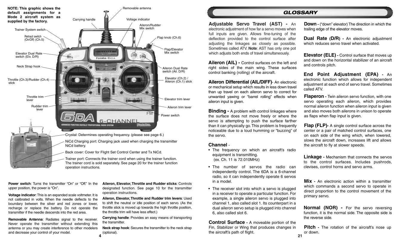
Power switch: Turns the transmitter “On” or “Off.” In theupper position, the power is “On”.
Voltage indicator:This is an expanded scale voltmeter. It isnot calibrated in volts. When the needle deflects to theboundary between the silver and red zones or lower,recharge or replace the battery. Do not operate thetransmitter if the needle descends into the red area.
Removable Antenna: Radiates signal to the receiver.Never operate the transmitter without extending thisantenna or you may create interference to other modelersand decrease your control of your model.
Aileron, Elevator,Throttle and Rudder sticks: Controlsdesignated function. See page 10 for the transmitter operation instructions.
Aileron, Elevator, Throttle and Rudder trim levers: Usedto shift the neutral or idle position of each servo. (As thethrottle stick is moved up towards the high throttle position,the throttle trim will have less effect.)
Carrying handle: Provides an easy means of transportingthe transmitter.
Neck strap hook: Secures the transmitter to the neck strap(optional).
Rudder trimlever
Flap/ElevatorMix switch
Aileron/RudderMix switch
Aileron Dual Rateswitch (Ail. D/R)
Voltage indicator
Removable antenna
Carrying handle
Elevator Dual Rate switch (Elv. D/R)
Neck Strap hook
Retract switch(On/Off) (Ch.5)
Trainer System switch
Throttle (Ch.3)/Rudder (Ch.4)stick
Elevator (Ch.2) /Aileron (Ch.1) stick
Elevator trim lever Throttle trimlever
Power switch
Aileron trim lever
Flap knob (Ch.6)
NOTE: This graphic shows thedefault assignments for aMode 2 aircraft system assupplied by the factory.
Crystal: Determines operating frequency. (please see page 6.)
NiCd Charging port: Charging jack used when charging the transmitterNiCd battery.
Back cover: Cover for Flight Set Control Center and Tx NiCd.
Trainer port: Connects the trainer cord when using the trainer function.The trainer cord is sold separately. See page 20 for the trainer functionoperation instructions.

Retract switch (Ch.5): Controls the raising and lowering of retractable landing gear orother feature. Not all models will use this function. (see page 18)
Flap knob: Controls the flap servo(Ch.6).Turning clockwise lowers flaps. Turningcounter-clockwise raises flaps.(see page 19)
Flap Control lever: Sets fixed position for flap movement to ease use in flight.
See page 19 for use of Flap Control lever.
Dual Rate switch (Ail. D/R and Elv. D/R):Used to set and reduce the servo travel by flipping each Dual Rate switch. (seepage 14)
Trainer switch: Controls the link between the instructor and student transmitters whenusing the trainer function. The student transmitter can only be operated when thisswitch is being held “on”. (see page 20)
20 5
FLAP FL/ELE
M
IX
OFF
ON
• Never turn on the student transmitterpower switch. Turning on the power switchwill cause interference and a crash.
• Set the student and instructor transmitterfunctions and trims to the same settings.For example, if the direction of operation isreversed, control may be lost and the planemay crash.
• The student Tx can only be an FM (PPM)type transmitter.
Operating Instructions• With both transmitters off, plug the trainer
cord into the instructor’s Tx, then the student’s.
• Turn on instructor’s Tx. DO NOT turn on thestudent Tx.
• Check proper operation of all controls.• Hold the trainer switch “on” and check the
operation of all controls of the student Tx.• Alternating from instructor to student, set
throws and trims to be identical.
BEFORE EACH FLIGHT
• Confirm that you have exclusive use of your frequency.
• Check your Tx and Rx battery voltage.
• Turn on Tx first, then Rx.
• Check direction and smooth movement of every control surface.
• Range check the radio by having another person hold the model. With the antenna fully
collapsed, walk at least 50 feet from the model. Ensure all control surfaces function properly.
• Have fun!!
TRAINER FUNCTION
PREPARE TO FLY
The trainer function is a very effective way to train students. To use it, the optional trainer cord TC-FM is necessary. The special trainer cord can be connected to all Futaba FM and PCM transmittersmanufactured after 1991.
1
ON SD
2 3 4 5 6 7 8 9
100%
50%AIL
100%
50%ELE
100%
25%HI
100%
25% SERVO REVERSE
FLP, ELEAIL, RUD
FLPRN
LO
100%
50%AIL
100%
50%ELE
100%
50%RUD
100%
50%FLP>ELE AIL>RUD
FLP>DIFF
100%
50%
1
ON SD
2 3 4 5 6 7 8 9
100%
50%AIL
100%
50%ELE
100%
25%HI
100%
25% SERVO REVERSE
FLP, ELEAIL, RUD
FLPRN
LO
100%
50%AIL
100%
50%ELE
100%
50%RUD
100%
50%FLP>ELE AIL>RUD
AIL>DIFF
100%
50%
Servo Reversing dipswitches: Switches thatreverse the direction ofoperation of a servo.The numberscorrespond to thechannel number of eachcontrol function.
The lower position is thenormal side and theupper position is thereverse side.
(see page 11)
AST (AdjustableServo Travel) (AIL,ELE, RUD):Used to adjust totalservo travel.Adjusts both endsof the servo travelat one time.(see page 13)
MIX adjustments(AIL to RUD, FLAP to
ELE, AIL Differential):Used to adjust theamount of movement ofsecond servo.(see pages 15,17&19)
Dual Rate pots (Ail./Elv.):Used to reduce the servotravel when flipping eachDual Rate switch. The travelreduction for the aileron andelevator may be setindependently.(see page 14)
Trainer Jack(Trainer Cord TC-FM
sold separately)
Retractswitch(Ch.5)
FLIGHT SET CONTROL CENTER
Mixing Activation dip switches:switches that activate the electronicmixes and features.
(see pages 15&19)
Throttle EPA (End PointAdjustment) pots (Low/High)
Used to adjust throttle servotravel limits.Servo travel atboth end points can beadjusted independently in eachdirection. (see page 12)

6 19
• If the model has separate flaps (not flaperons,as covered on page 16) plug the flap servo intochannel 6 on the Rx.
• Most models will change pitch upon deployingflaps (some will climb; others dive).Test fly themodel and determine the direction andamount of elevator throw required to correctfor this change.
• Activate this feature with dip switch #7 andthen turn it on with the mix switch. Adjust theamount as required to match the amount ofelevator required in flight.
Plane balloonswhen flaps drop
FLAPS FLAP-TO-ELEVATOR MIXING
BEFORE
AFTER
Flap Control lever:
By using the flap control lever, you can set themaximum up deflection of the flaps. This way, youcan keep from accidentally applying flaps asspoilers during flight, and do not need to look forcenter on the knob while in flight.
To use, simply turn the flap dial until the flaps areat the upmost position you desire. Now slide theflap control lever over the splines of the flap knobso that the long arm is touching the side of theradio. Now the flap knob can not be rotatedcounterclockwise any further, and you have thelarge lever available to easily deploy flaps!
Transmitter (Tx)
• Digital Proportional 6CH FM Two-Stick 72MHz♦
Transmitter
• Flight Set Adjustment Control Center
• Narrow-band Transmission Technology
• Fully Proportional Flap Control
• Flaperon with Adjustable Aileron Differential Capability
• Separate Elevator and Aileron Dual Rate Switches and Adjustments
• Flap-to-Elevator (not available simultaneously with flaperon) and Aileron-to-Rudder
Separate Mix Switches and Adjustments
• Two-Position Retract Switch for Gear Operation
• Momentary-on Trainer Switch
• Analog Battery Voltage Indicator
• Electronic Analog Trim Adjustments on All Four Primary Control Surfaces
• All-Channel Servo Reversing Switches
• Throttle Hi and Low EPA Adjustments
• Elevator, Aileron and Rudder AST Adjustments
• 9.6v NiCd Rechargeable Battery and Dual Charger Included
Receiver (Rx) FP-R127DF* ** Servos (Sx) S3004
• Interchangeable Crystal, 72MHz* Freq.** • Torque: 42 oz.-in. at 4.8V [2.99 Kg*cm]
• Size: .82" x 1.39" x .82" • Size: .77" 1.59" x 1.41"
[20.8mm x 35.3mm x 20.8mm] [19.6mm x 40.4mm x 35.8mm]
• Weight: 1.50 oz. [42g] • Speed: .22 sec/60 degrees
• Dual Conversion Narrow Band Technology • Weight: 1.50 oz. [42g]
• 4.8v NiCd Rechargeable Battery Included
*This device complies with part 15 of the FCC rules. Operation is subject to the following two conditions.
1) This device may not cause harmful interference.
2) This device must accept any interference received including interference that may cause undesired operation.
**For proper operation and the safety of all concerned, please be sure that if you choose to change your receiver's frequency to stay with in the proper
band. If your receiver was originally on channels 11-35, then it is 'low band'. If it was on 36-60, then it is 'high band'. Do not change frequencies outside
of the band of your receiver.
It is against FCC regulation for anyone but a licensed technician to change your transmitter's frequency. You may replace a damaged crystal of the
same channel, but the radio must be properly retuned after transmitter channel change.
FEATURES & SPECIFICATIONS
♦6DA systems soldoutside the USA include:
• R138DF Receiver (Rx) oneither 35 or 40MHz.
• 6DA Transmitter (Tx) oneither 35 or 40MHz.
FLAP FL/ELE
M
IX
OFF
ON
1. Rotate Flap knobto operate flaps.
1. Deploy flaps usingthe Flap knob.
2. Observe flightcharacteristics of yourairplane when flaps
are deployed.
3. ActivateFLP/ELE dip
switch and adjustthe FLP>ELE pot.
4. Level flight withFlap to Elevator
mixing.

18 7
• First, follow your model’sinstructions carefully for properinstallation and fitting of the retractmechanisms. [If you are usingmechanical retracts, the mostsecure means of operation is witha true “retract servo” such asFutaba’s S136G (not included).See "Retract Servo" in theglossary on page 21.]
• The retract channel has no AST (Adjustable Servo Travel).Therefore, you MUST properlyset it up mechanically to ensure“lock” on the gear and to avoidbinding or buzzing of the servo.
• When everything is operatingproperly by hand, plug the retractservo into slot 5 on the Rx. Testthe gear’s movement. Reversethe servo, if required, per theinstructions on page 11.
RETRACTABLE LANDING GEAR
BEFORE
AFTER
• The transmitter includes a genuine Futaba 8-cellNiCd battery pack, NT8S, already installed.Please see page 3 regarding information onproper disposal of these batteries.
• Do NOT attempt to use your radio prior toproperly charging both your transmitter andreceiver battery packs. Using the included wallcharger, plug your transmitter charge lead intothe charge jack on your transmitter, and plug thereceiver charge lead into the receiver pack’slead and allow the batteries to charge for 16-20hours prior to use. (Be sure both LED chargerlights are lit.)
• Always charge yourradio system overnightwith the wall charger orotherwise peak thebatteries prior to use.Although the wallcharger’s average chargerate is approximately50mAh, because of theresistance of thebatteries it is always bestto use the wall charger for at least 8 hours priorto flying. Use a loading voltmeter to check thevoltage of the receiver pack between each use,charging the receiver battery to its peak voltageprior to using it any time the voltage indicatorreads less than 5.0 volts for the receiver pack.
• You may use an optional 5-cell, 6-volt receiverbattery pack (NR5F) with your new radiosystem. Note, however, that while 6 voltsprovides more torque and speed from theservos, it also provides a significantly shorterrun time for the same capacity and may shortenthe life of the servos proportionally.
This can be confusing, so it may help tocompare the current in the battery to water in abucket. If you have four small holes in the
bucket, the water will come out at a certain rate.Add a fifth hole the same size, and you’resupplying more water (increasing the currentand therefore making the servos stronger ANDfaster); however, the bucket empties 20%sooner than when it only had four holes.
• NiCd batteries discharge, or lose power, on agradual curve. However, this curve is not a flatline; that is to say, if the pack uses 100mA in thefirst 10 minutes it will not continue to provide100mA every 10 minutes until it is fullydischarged. Rather, it starts out providing at acertain rate, then its output drops off in a curvewhich becomes very steep as the packapproaches discharge. Because of thisdischarge curve, it is imperative that you checkbattery voltage immediately prior to each use.
ServoScrews
RubberIsolators
Grommets
ServoRail
BATTERY CARE
INSTALLING SERVOS
Assemble and mount your servos.Note: the grommets must be installed as shown(large end against the aircraft) to provide properisolation. A small drop of medium CA on eachisolator prior to installation will secure it to theservo and ease installation.
Slot 5
1. Plug the retract servointo slot 5.
2. Activate Retract switch.
3. Retracts come up.

8 17
• For aerodynamic reasons, if amodel’s two ailerons move thesame amount, some models willyaw, or pull, toward the droppedaileron.For example, if the modelergives left aileron inputs, the rightaileron drops and the left aileronrises. If they move the sameamount, besides rolling to the left,the model will also yaw to the right.Aileron differential decreases theamount of down travel for eachaileron without affecting the uptravel. By test flying and adjustingthis feature, the model can bemade to track straighter.
• Decrease the downward travel ofthe twin aileron servos byadjusting the aileron differentialpot. Doing so will help your modelto roll axially and not “barrel roll,”turning toward the lowered aileron,as shown in the sketch.
• If using the flaperons as flapsAND differential, be sure to checkthat you have sufficient aileroncontrols even when you have fullflap throw. Decrease differentialuntil safe control is available.
AILERON DIFFERENTIAL
BEFORE
AFTER
Servo Connection
• Plug the aileron servo into slot 1.• Plug the elevator servo into slot 2.• Plug the throttle servo into slot 3.• Plug the rudder servo into slot 4.• Plug the gear servo (optional) into
slot 5.• Plug the flap servo (optional) into
slot 6.Not used with 6-CH transmitter
To Rx battery
SETTING UP YOUR RADIO GEAR
• Connector Connection:Insert the receiver, servo, andbattery connectors fully and firmly.
• Receiver Vibration-proofing:Vibration proof the receiver andbattery by wrapping them insponge rubber or similar material.If the receiver may get wet,waterproof it separately byplacing it in a plastic bag orballoon. If the receiver issubjected to strong vibration andshock or gets wet, it may operateerratically and cause a crash.
• Receiver Antenna:Do not cut or bundle the receiverantenna. Also, do not bundle theantenna together with the servolead wires. Cutting or bundling thereceiver antenna will lower thereceiver sensitivity and shortenthe flight range and cause acrash. Attach the antenna to thetop of the tail.
• Power Switch Installation:When installing a receiver powerswitch to the fuselage, cut arectangular hole somewhat largerthan the full stroke of the switchknob and install the switch so itmoves smoothly from ON to OFF.Always install the switch so it will notcome into direct contact with engineoil, dust, etc. Generally, install theswitch to the fuselage on the sideopposite the muffler exhaust. Plugthe receiver battery into the blackbattery lead on the switchharness. Be sure the powerswitch is “OFF.” Plug the redswitch harness lead into the “B”battery slot on the receiver.
Flaperonor flaps
Gear
Rudder
Throttle
Elevator
Aileron
1. Give aileron stick inputduring flight.
2. This illustrates whathappens when both
ailerons have thesame throw.
4. Rolls becomestraighter.
3. Decrease theAileron
Differential pot.

16 9
• Twin aileron servos are a very beneficial set upwhich allows the modeler more precise controland adjustment of the aileron response of themodel, as well as providing “flaperons” — themovement of both aileron servos in the samedirection at the same time to act as flaps.
• Plug the right aileron servo into channel 1 andthe left aileron servo into channel 6. Noticethat moving the aileron stick moves only theright aileron servo.
• Activate the flaperon feature with dip switch #9.Note that both aileron servos now move with theaileron stick. Check the servo direction for bothservos and adjust as required.
• The two aileron servos now operate in unison,creating flap action when the flap knob is turned.This feature is always active, so take care not tomove this knob accidentally in flight. See page19 for instructions on using the flap control lever.
• This radio cannot support two aileron servos on separate receiver channels AND a separate flap servo at the same time. If your modelrequires both twin aileron servos and flaps, you must use a y-harness to drive the two aileron servos. Also note that this radio cannotsupport a flaperon-to-elevator mix. If you have flaperons active, the flap-to-elevator pot sets up aileron differential, not a mix.
CH 1
CH 6
DUAL AILERON SERVOS/FLAPERONS USING THE FREQUENCY BOARD
NON-SLIP ADJUSTABLE STICK LEVER
The length of the stick can be adjusted.
1. Unlock, the two heads, A and B, by turning them in the arrow directions.
2. Adjust the stick to the most comfortable length.
3. Lock the heads by turning them in the opposite direction of the arrows.
1. Stick the band number seal to thefrequency board.
2. Install the frequency board to the antenna.
3. Pass the frequency board over the smallpart of the antenna and slide it to the large part.
4. Cut off the unused side along the slot withcutters, etc.
BEFORE
AFTER1. Plug each
aileron into theproper channel.
4. Activatethe Flaperondip switch.
6. Move flapknob when flap
is desired.
7. When the flap knob is moved, bothailerons move down.
5. Both aileronsshould move when
the stick is deflected.
2. Deflectaileron stick.
3. only oneaileron moves.
10 15
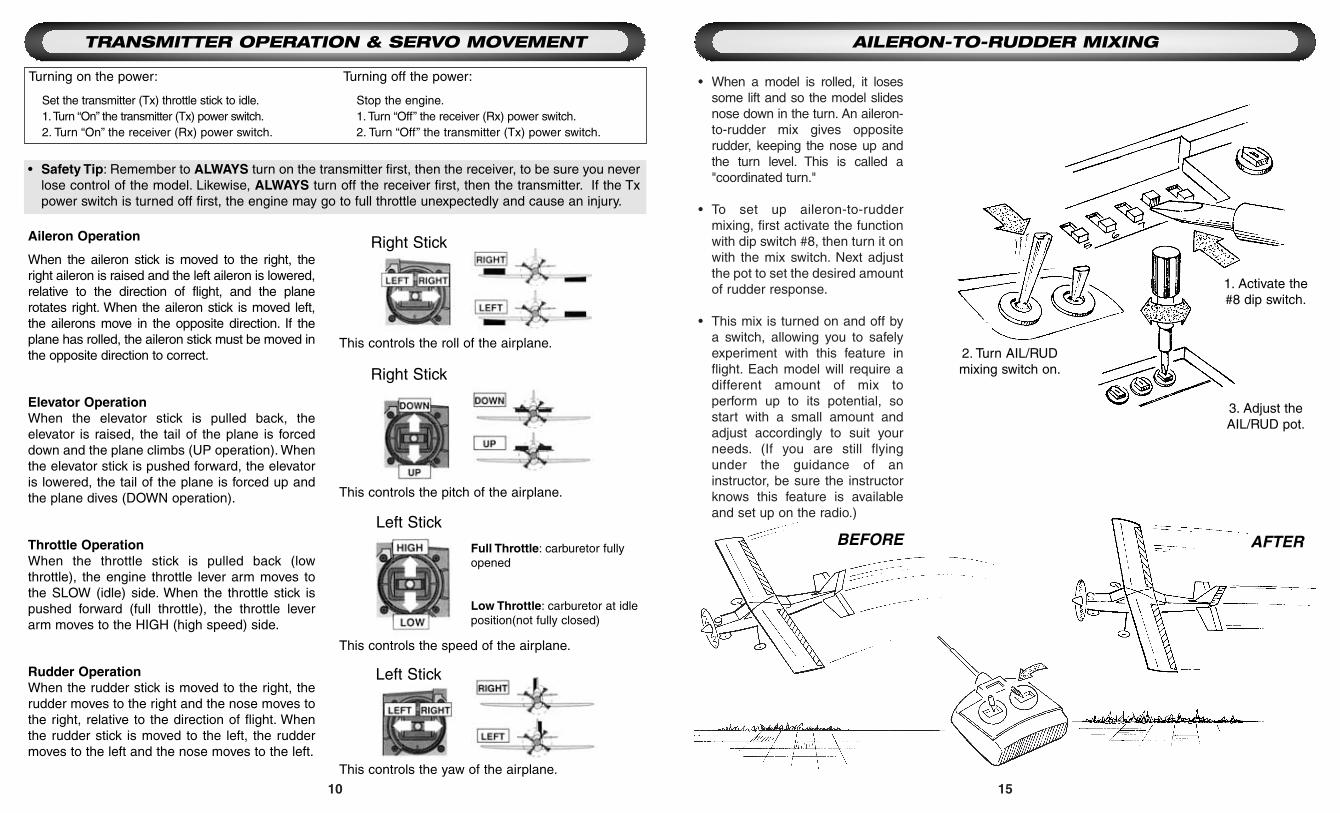
• When a model is rolled, it losessome lift and so the model slidesnose down in the turn. An aileron-to-rudder mix gives oppositerudder, keeping the nose up andthe turn level. This is called a"coordinated turn."
• To set up aileron-to-ruddermixing, first activate the functionwith dip switch #8, then turn it onwith the mix switch. Next adjustthe pot to set the desired amountof rudder response.
• This mix is turned on and off bya switch, allowing you to safelyexperiment with this feature inflight. Each model will require adifferent amount of mix toperform up to its potential, sostart with a small amount andadjust accordingly to suit yourneeds. (If you are still flyingunder the guidance of aninstructor, be sure the instructorknows this feature is availableand set up on the radio.)
AILERON-TO-RUDDER MIXINGTRANSMITTER OPERATION & SERVO MOVEMENT
BEFORE AFTER
Right Stick
Right Stick
Left Stick
Left Stick
Aileron Operation
When the aileron stick is moved to the right, theright aileron is raised and the left aileron is lowered,relative to the direction of flight, and the planerotates right. When the aileron stick is moved left,the ailerons move in the opposite direction. If theplane has rolled, the aileron stick must be moved inthe opposite direction to correct.
Elevator OperationWhen the elevator stick is pulled back, theelevator is raised, the tail of the plane is forceddown and the plane climbs (UP operation). Whenthe elevator stick is pushed forward, the elevatoris lowered, the tail of the plane is forced up andthe plane dives (DOWN operation).
Throttle OperationWhen the throttle stick is pulled back (lowthrottle), the engine throttle lever arm moves tothe SLOW (idle) side. When the throttle stick ispushed forward (full throttle), the throttle leverarm moves to the HIGH (high speed) side.
Rudder OperationWhen the rudder stick is moved to the right, therudder moves to the right and the nose moves tothe right, relative to the direction of flight. Whenthe rudder stick is moved to the left, the ruddermoves to the left and the nose moves to the left.
Full Throttle: carburetor fullyopened
Low Throttle: carburetor at idleposition(not fully closed)
This controls the roll of the airplane.
This controls the pitch of the airplane.
This controls the yaw of the airplane.
This controls the speed of the airplane.
Turning on the power:
Set the transmitter (Tx) throttle stick to idle.1.Turn “On” the transmitter (Tx) power switch.2. Turn “On” the receiver (Rx) power switch.
Turning off the power:
Stop the engine.1. Turn “Off” the receiver (Rx) power switch.2. Turn “Off” the transmitter (Tx) power switch.
• Safety Tip: Remember to ALWAYS turn on the transmitter first, then the receiver, to be sure you neverlose control of the model. Likewise, ALWAYS turn off the receiver first, then the transmitter. If the Txpower switch is turned off first, the engine may go to full throttle unexpectedly and cause an injury.
2. Turn AIL/RUDmixing switch on.
1. Activate the#8 dip switch.
3. Adjust theAIL/RUD pot.

14 11
• Servo Reversing is a feature thatallows you to correct thedirection a servo travels withoutmechanically changing thelinkage in your model.You simplyflip a dip switch on your FlightSet Adjustment Control Centerand the polarity of the servocontrol reverses.
• Check the direction of all servooperation and reverse any servoas needed. For example, if therudder moves left when rightrudder command is given, thenmove the servo reversing switchfor channel 4 from NOR to REV.Check that the rudder nowoperates properly.
Flight SetAdjustment
Control Center
SERVO REVERSING
BEFORE
AFTER
• A “dual rate,” or second, lower rate,on the model’s ailerons orelevators can make the modeleasier to handle at higher speeds,while keeping plenty ofresponsiveness available on thehigh rate when flying at slowspeeds such as landing.
• Check the model’s instructions,and determine if the manufacturerhas provided desired low ratesettings for aileron and elevator.Pull the elevator rate switch to thedown position and adjust theelevator dual rate pot to reach thisdesired throw. Repeat for aileron.
Correct Low Rate Throw
Low Rate same as High Rate
ELEVATOR AND AILERON DUAL RATES
BEFORE
AFTER
Turning the Dual Ratepot counterclockwise
decreases the servo’s travel.
1. Move rudderstick right.
2. Rudder movesto the left.
4. Rudder movesto the right.
3. Move the servo reversedip switch.
1. Pull the Dual Rateswitch down to the
low position.
4. Adjust the DualRate pot to give the
correct throw.
5. Check to see thatthe rate is correct.
2. Move the stickto full deflection.
3. Check the throw.

12 13
• Move the throttle stick to fullthrottle. Does the barrel of theengine’s carburetor opencompletely? Does it opencompletely before the servo hasmoved its full distance, so theservo is pushing against the barrelat full throttle causing the servo to“buzz” or the pushrod to flex?Always correct the throw asclosely as possible by adjustingthe linkage. Then use the ThrottleHigh EPA pot to fine-tune the fullthrottle setting.
• Now close the throttlecompletely, including pulling thethrottle trim closed. Does thebarrel just close completely onyour engine as the trim hitsbottom? If not, adjust the ThrottleLow EPA pot until it does, so theengine can be shut off safelyfrom the radio.
ServoBuzzing
PushrodBowing
When adjustedcorrectly, there is noservo buzz or bowing
of the pushrod
Turning the Throttle HighEPA pot counterclockwise
decreases the throttleservo travel.
THROTTLE END POINT ADJUSTMENTS (EPA)
BEFORE
AFTER
• Read your model’s instructions todetermine the proper distanceeach control surface should move.This is called “throw.” If the model'sinstructions specify a “High” and“Low” rate, use the High rate here.With the dual rate switches in the“off” positions, move each controlits full distance and measure thethrow. Note that it is very commonfor your initial installation/set up toprovide you more or lessmovement of the control surfacethan is desirable to fly the aircraft.
• Always adjust the throw as closelyas possible first by moving theclevises in or out on the model'scontrol horns and servo arms.(Using AST settings below 80%will significantly affect the precisionof the servos’ response to yourcommands.) If needed, adjust theAST pots for each surface until theproper throw is set.
Too Much Throw Correct Throw
ADJUSTABLE SERVO TRAVEL (AST)
BEFORE AFTER
Turning the AST potcounterclockwise
decreases the servo’s travelat full stick deflection.
1. Move the throttle stickto full up.
1. Move the stick tofull deflection.
3. Adjust the properAST pot.
4. Confirmthe throw is
correct.2. Measure the
throw.
2. Adjust the servo'send point.