instruction manual - hobbicomanuals.hobbico.com/gpm/gpma0439-manual.pdf · instruction manual...
TRANSCRIPT
INSTRUCTION MANUAL
WARRANTYGreat Planes Model Manufacturing Co. guarantees this kit to be free from defects in both material and
workmanship at the date of purchase. This warranty does not cover any component parts damaged by use ormodification. In no case shall Great Planes' liability exceed the original cost of the purchased kit. Further, GreatPlanes reserves the right to change or modify this warranty without notice.
In that Great Planes has no control over the final assembly or material used for final assembly, no liability shall beassumed nor accepted for any damage resulting from the use by the user of the final user-assembled product. By theact of using the user-assembled product, the user accepts all resulting liability.
If the buyers are not prepared to accept the liability associated with the use of this product, they areadvised to return this kit immediately in new and unused condition to the place of purchase.
P.O. Box 788
LEA4P03 V1.1 LEARJET is a registered trademark of LEARJET, INC.
Urbana, IL 61801 (217) 398-8970
Entire Contents © Copyright 1995
INTRODUCTION..............................................................2PRECAUTIONS.................................................................3DECISIONS YOU MUST MAKE........................................3
Engine and mount .......................................................3Fixed or retractable landing gear.................................3
PREPARATIONS...............................................................3Accessories and additional items................................3Optional retracts. ........................................................4Building supplies and tools..........................................4Types of wood .............................................................4Common abbreviations ...............................................4What about adhesives?...............................................5Die-cut patterns.....................................................6 & 7Get ready to build ........................................................8
BUILD THE TAIL SURFACES...........................................8Vertical fin and rudder .................................................8Stabilizer and elevators .............................................10
BUILD THE WING ...........................................................11Prepare subassemblies.............................................11Assemble the wings .................................................12Completing the wing panels ......................................14Join the wings............................................................16Sand the leading edge ..............................................18Assemble and install the tip tanks.............................18
BUILD THE FUSELAGE ................................................19Frame the fuselage ...................................................20Mount the engine ......................................................26Install the canopy and cowl .......................................26Mount the wing.............!............................................28
FINAL ASSEMBLY ..........................................................29Install the tail group ...................................................29Assemble the engine nacelles...................................30Balance the airplane laterally ....................................30
FINISHING.......................................................................31Fuel proofing .............................................................31Final sanding before covering ...................................31Applying MonoKote" covering ...................................31Covering sequence ...................................................32Painting .....................................................................32Apply the decals . .....................................................32
INSTALL THE RADIO AND CONTROL SURFACES .....32Install receiver and switch .........................................32Hinge and hook up the controls.................................33Recommended control surface throws......................35
COMPLETE THE MODEL...............................................36Install the fuel tank ....................................................36Install retractable landing gear ..................................36Install fixed landing gear............................................36Install the nacelles and tip tanks ...............................37Balance the model fore and aft .................................37
THE MAIDEN VOYAGE...................................................37Balance the propeller ................................................37Preflight .. . .. ............................................................38Range check your radio ............................................38Engine safety precautions .........................................38AMA Safety Code......................................................38
FLYING............................................................................39Find a safe place to fly ..............................................39Takeoff.......................................................................39Flight......................................................................... 39Landing......................................................................40
TWO VIEW DRAWING ....................................................40
Your Great Planes Learjet is not a toy, but rather asophisticated, working model that functions very much like anactual airplane.
Because of its realistic performance, the Learjet, if notassembled and operated correctly, could possibly causeinjury to yourself or spectators and damage property.
To make your R/C modeling experience totallyenjoyable, we recommend that you get experienced,knowledgeable help with assembly and during yourfirst flights. You'll learn faster and avoid risking your modelbefore you're truly ready to solo. Your local hobby shop hasinformation about f ly ing clubs in your area whosemembership includes qualified instructors.
You can also contact the national Academy of ModelAeronautics (AMA), which has more than 2,300 charteredclubs across the country Through any one of them,instructor training programs and insured newcomer trainingare available.
Contact the AMA at the address or toll-free phonenumber below.
Academy of Model Aeronautics5151 East Memorial DriveMuncie, IN 47302-9252
Tele. (800) 435-9262Fax (317) 741-0057
Congratulations! Thank you for purchasing the GreatPlanes Learjet!
This Learjet is a sport model of the full-size Learjet 35A. Itwas designed by noted Ultra Sport'" modeler JimFeldmann It's easy to build and fly, predictable, fairlyaerobatic and has no "bad habits," making it a great sportairplane. Traditional Great Planes quality and ruggednessis evident throughout this kit, making this an airplane you'llwant to take along every time you go to the flying field.
2
This is not a beginner's airplane! While the Learjet isfairly easy to build and flies great, we must discourage youfrom selecting this kit as your first R/C airplane It can befast, highly maneuverable and lacks the self-recoverycharacteristics of a good basic trainer such as the GreatPlanes PT Series On the other hand, if you have alreadylearned the basics of R/C flying and you are able to safelyhandle a "trainer" airplane, the Learjet is an excellentchoice to improve your skills and learn new maneuvers.
Please inspect all parts carefully before starting tobuild! If any parts are missing, broken or defective, or ifyou have any questions about building or flying thisairplane, please call us at (217) 398-8970. If you arecalling for replacement parts, please reference the partnumbers and the kit identification number (stamped onthe end of the carton) and have them ready when calling.
1. You must build the plane according to the plan andinstructions. Do not alter or modify the model, as doing somay result in an unsafe or unflyable model In a few casesthe plan and instructions may differ slightly from thephotos In those instances you should assume the planand written instructions are correct
2. You must take time to build straight, true and strong.
3. You must use a proper R/C radio that is in first classcondition, the correct sized engine and correctcomponents (fuel tank, wheels, etc ) throughout yourbuilding process.
4 You must properly install all R/C and other components sothat the model operates properly on the ground and in the air.
5. You must test the operation of the model before the firstand each successive flight to insure that all equipment isoperating, and you must make certain that the model hasremained structurally sound Be sure to check the nylonclevises often, and replace if they show signs of wear.
6. You must fly the model only with the help of acompetent, experienced R/C pilot if you are not alreadyan experienced and knowledgeable R/C pilot at this time.
NOTE We, as the kit manufacturer, can provide youwith a top quality kit and great instructions, but ultimatelythe quality of your finished model depends on how youbuild it, therefore, we cannot in any way guarantee theperformance of your completed model, and norepresentations are expressed or implied as to theperformance or safety of your completed model
Remember: Take your time and follow directions to endup with a well-built model that is straight and true.
Engine And Mount
The recommended engine size range is as follows'40 - .50 cubic inch displacement 2-stroke.
This kit includes a Great Planes EM2840 engine mountthat fits nearly all 2-stroke engines in the recommendedrange If you prefer, you may purchase a custom enginemount for your engine, or you may choose to installshock-absorbing, rubber-cushioned mounts.
Fixed or retractable landing gear
The Great Planes Learjet includes prebent wire landinggear for fixed installation To add to the sleek and realisticappearance of your model in flight, you may want toinstall retracts We have included instructions for bothinstallations However, you will need to purchase a set ofthree mechanical retracts, two servos, and a "Y" harnessif you choose the retract option Pneumatic retracts maybe used in place of the suggested mechanical units if youprefer
D Four or five channel radio with 4 to 6 servos(optional retracts)
D 6" Servo extension cordD Propellers (See engine instructions)D 2-1/4" Jet spinner
(white GPMQ4542) (black GPMQ4540)D 6 to 8 oz Fuel tank
(6 oz GPMQ4102 8 oz GPMQ4103)D 2 oz Thin CA adhesive (GPMR6015)D 2 oz Medium CA adhesive (GPMR6009)D 1 oz Thick CA adhesive (GPMR6014)D 6-Minute epoxy (GPMR6045)D 30-Minute epoxy (GPMR6047)D 1-3/4" Nose wheel (GPMQ4220)D 2" Main wheels (GPMQ4221)D 5/32" Wheel collars (6) (GPMQ4306)D Model covering (2 - 3 rolls)
(Top Flite MonoKote" Covering)D Medium fuel tubing (GPMQ4131)D 1/2" thick Latex foam rubber padding (HCAQ1050)D Sliver solder (recommended) (GPMR8070 w/flux)D Switch & charge jack mount (optional) (GPMM1000)D Fuel filter (optional) (GPMQ4150)D Fuelproof paint
(see "Painting" section of instructions on page 32)3
D Tricycle retract gear - (HCAP4000)D Retract servo (Futaba S136G or similar)D Standard servo for nose gear retractD Servo "Y" harnessD 1-1/4" x 5/32" Wheel axles (3) (GPMQ4280)D 2-56 x 12" Threaded wire pushrods (2) (GPMQ3750)D 2-56 x 36" Threaded wire pushrods (1) (GPMQ3716)D Screw-Lock pushrod connector (3) (GPMQ3870)D 4-40 x 1/8" Set screws
*ltems in parentheses (GPMQ1234) are suggested partnumbers recognized by distributors and hobby shops andare listed for your convenience GPM is the Great Planesbrand, HCA is the Hobbico® brand, TOP is Top Flite
On our workbench, we have four 11" Easy-Touch BarSanders, equipped with #50, #80, #150 and #220-gntsandpaper This setup is all that is required for almostany sanding task Custom sanding blocks can be madefrom balsa for sanding hard to reach spots We also keepsome #320-gnt wet-or-dry sandpaper handy for finishsanding before covering
D Hand or electric drill *D Drill bits 1/16", 3/32", 7/64" or #35, 1/8", #29 or
9/64", 3/16", #10 or 13/64", 15/64", 17/64" and 1/4"D Sealing iron - (TOPR2100)D Hot sock (optional) - (TOPR2175)D Heat gun (optional) - (TOPR2000)D Razor sawD #1 knife handle - (XACR4305)D #11 Blades - (HCAR0311 pkg of 100)D Common and needle nose pliersD Screwdrivers (phillips and flat)D T-Pins - (HCAR5100 small, HCAR5150 medium,
HCAR5200 large)D Straightedge - (Fourmost Non Slip FORR2149)D Masking tapeD Sandpaper (coarse, medium, fine grit)D Sanding blocks or Great Planes Easy-Touch"
Bar Sander (GPMR6170 -11" & GPMR6172 - 22")D Waxed paperD Lightweight balsa filler - (HCAR3401)D 5/32" brass tube (optional)D 1/8" brass tube (optional)D Tap wrenchD 1/4-20 Tap - (GPMR8105 w/dnll bit)D IsopropyI rubbing alcohol (70%)D Dremel® Moto Tool® or similar w/sanding drum and
cutting burr (optional)D Kyosho" curved scissors (optional) - (KYOR1010)
Great Planes Easy-Touch Bar Sanders are made fromlight-weight extruded aluminum and can be found atmost hobby shops The sanders are available in twosizes - 11" (GPMR6170) for most general purposesanding and 22" (GPMR6172) for long surfaces such aswing leading edges We recommend using the 2-1/4"wide self adhesive sandpaper sold in 12' rolls by GreatPlanes The sandpaper is available in three different gritsizes - #80-grit (GPMR6180), #150-grit (GPMR6183)and #220-grit (GPMR6185) Standard sandpaper can beattached by gluing it to the sander with rubber cement.Apply the rubber cement to both the bottom of the sanderand the back of the sandpaper When both surfaces aredry to the touch, press the sandpaper firmly onto thesander Spray adhesive can be used for this purpose butit's much harder to remove the sandpaper when youneed to replace it Use a knife blade for cuttingsandpaper, not your good scissors!
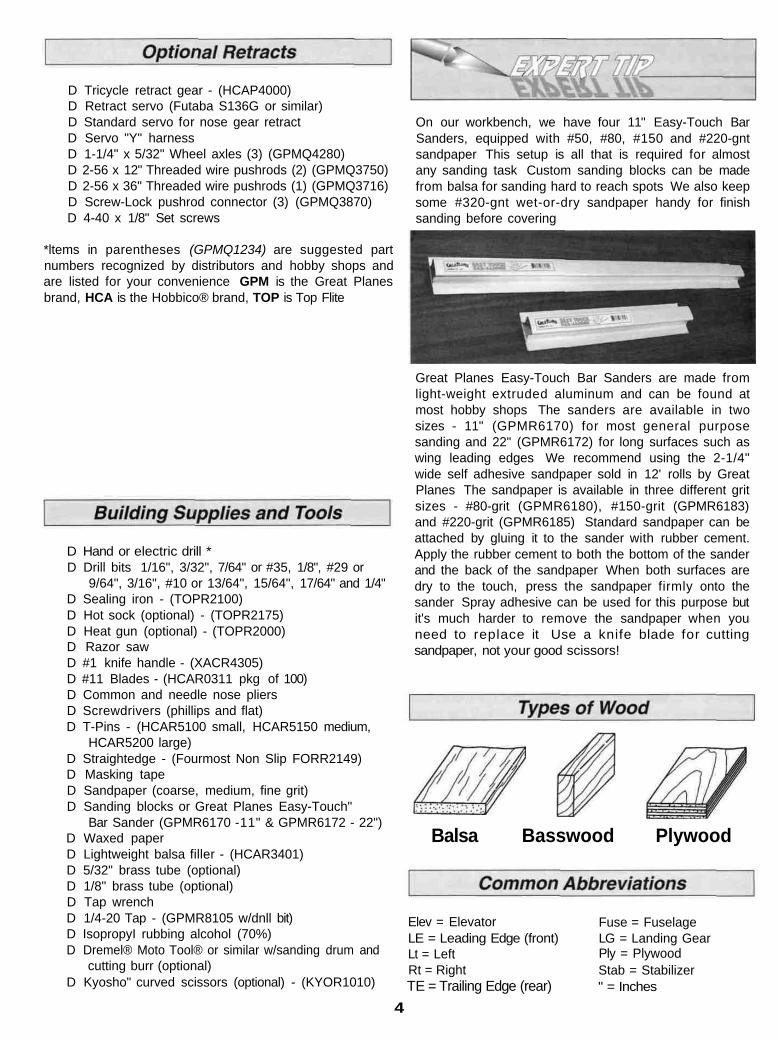
Balsa Basswood Plywood
Elev = Elevator Fuse = FuselageLG = Landing GearPly = PlywoodStab = Stabilizer" = Inches
LE = Leading Edge (front)Lt = LeftRt = RightTE = Trailing Edge (rear)
4
We understand that the caliber of modelers likely to buildthe Great Planes Learjet may be rather high You mayalready know all about the types of adhesives you like touse However, due to its easy building features, many newbuilders may try their hand at the Great Planes Learjet Forthose modelers (experts may read along), we haveprovided some explanation about the variety of adhesivesused during construction of a model.
Cyanoacrylate or CA glue has changed the way modelsare built more than any other advance in modelingtechnology In the good ol' days, model cement likeAmbroid, Duco, Comet and Sigment were the glues ofchoice They all had a strong odor that could causedizziness, dried slowly (compared to CA) and becamebrittle with age CA, on the other hand, is stronger, worksalmost instantly and is bottled in three different viscosities(thicknesses) CA is used for most glue joints, except whereepoxy is specified CA does emit rather strong fumes (somesay it's like tear gas) as it cures, so rule number one is towork in a well ventilated area. All CA glues work best ifthe joints are smooth and fit well.
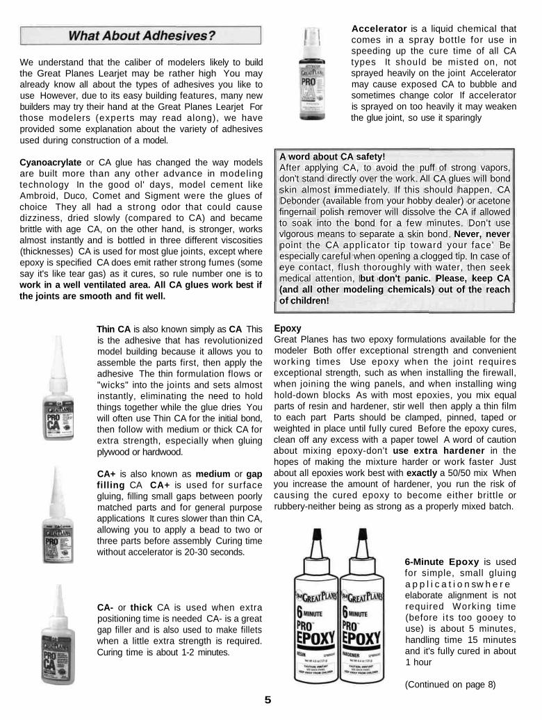
Accelerator is a liquid chemical thatcomes in a spray bottle for use inspeeding up the cure time of all CAtypes It should be misted on, notsprayed heavily on the joint Acceleratormay cause exposed CA to bubble andsometimes change color If acceleratoris sprayed on too heavily it may weakenthe glue joint, so use it sparingly
A word about CA safety!After applying CA, to avoid the puff of strong vapors,don't stand directly over the work All CA glues will bondskin almost immediately If this should happen, CADebonder (available from your hobby dealer) or acetonefingernail polish remover will dissolve the CA if allowedto soak into the bond for a few minutes Don't usevigorous means to separate a skin bond Never, neverpoint the CA applicator tip toward your face' Beespecially careful when opening a clogged tip In case ofeye contact, flush thoroughly with water, then seekmedical attention, but don't panic. Please, keep CA(and all other modeling chemicals) out of the reachof children!
Thin CA is also known simply as CA Thisis the adhesive that has revolutionizedmodel building because it allows you toassemble the parts first, then apply theadhesive The thin formulation flows or"wicks" into the joints and sets almostinstantly, eliminating the need to holdthings together while the glue dries Youwill often use Thin CA for the initial bond,then follow with medium or thick CA forextra strength, especially when gluingplywood or hardwood.
CA+ is also known as medium or gapfilling CA CA+ is used for surfacegluing, filling small gaps between poorlymatched parts and for general purposeapplications It cures slower than thin CA,allowing you to apply a bead to two orthree parts before assembly Curing timewithout accelerator is 20-30 seconds.
CA- or thick CA is used when extrapositioning time is needed CA- is a greatgap filler and is also used to make filletswhen a little extra strength is required.Curing time is about 1-2 minutes.
EpoxyGreat Planes has two epoxy formulations available for themodeler Both offer exceptional strength and convenientworking times Use epoxy when the joint requiresexceptional strength, such as when installing the firewall,when joining the wing panels, and when installing winghold-down blocks As with most epoxies, you mix equalparts of resin and hardener, stir well then apply a thin filmto each part Parts should be clamped, pinned, taped orweighted in place until fully cured Before the epoxy cures,clean off any excess with a paper towel A word of cautionabout mixing epoxy-don't use extra hardener in thehopes of making the mixture harder or work faster Justabout all epoxies work best with exactly a 50/50 mix Whenyou increase the amount of hardener, you run the risk ofcausing the cured epoxy to become either brittle orrubbery-neither being as strong as a properly mixed batch.
6-Minute Epoxy is usedfor simple, small gluinga p p l i c a t i o n s w h e r eelaborate alignment is notrequired Working time(before i ts too gooey touse) is about 5 minutes,handling time 15 minutesand it's fully cured in about1 hour
(Continued on page 8)
5
6
7

30-minute epoxy is usedfor extra strength (becauseit can penetrate longer) andwhere several parts mustbe aligned and checkedbefore it cures. Workingtime is about 25 minutes,handling time 2 hours, andit's fully cured in 8 hours.
Great Planes Pro" Wood Glue is an Aliphatic resin gluethat works well on all types of wood. It is non-toxic, virtuallyodorless and dries clear. Some people are sensitive to CAand epoxy fumes, so this is a good alternative for generalmodeling use. Its only drawback is that it is slow to cure,requiring the parts to be securely clamped, pinned or tapedwhile the glue dries.
Okay, you've got your work space ready, your tools are athand, and you know how to choose and use the right gluefor the job. Let's get started!
D 1. Unroll the plan sheets. Reroll the plan sheets insideout to make them lie flat.
D 2. Remove all parts from the box. As you do, determinethe name of each part by comparing it with the plan and theparts list included with this kit. Using a felt-tip or ball pointpen, lightly write the part name or size on each piece toavoid confusion later. Use the die-cut patterns shown onpages 6 and 7 to identify the die-cut parts and mark thembefore removing them from the sheet. Save all scraps. Ifany of the die-cut parts are difficult to punch out, do notforce them! Instead, cut around the parts with a hobbyknife. After punching out the die-cut parts, use your T-Baror sanding block to lightly sand the edges to remove anydie-cutting irregularities.
D 3. As you identify and mark the parts, separate theminto groups, such as fuse (fuselage), wing, fin, stab(stabilizer), and hardware.
D 1. The fin core is made up of left and right die-cut 1/8"plywood fin cores (LFC, RFC) and a die-cut 1/16" balsacenter fin core (CFC). Place the fin plan on your buildingboard and cover it with waxed paper. Place the 1/8" RFC(with one slot) over the plan and glue the 1/16" center fincore on top of it. Glue the 1/8" LFC (two slots) on top of thecenter fin core.
D 2. Sand the front and top edges of the fin core smooth,then pin the core over the plan. Assemble the balsa finframework from 1/4" x 1/2" and 1/4" x 3/4" balsa sticks onthe core as shown on the plan. Note: The frame is thinnerthan the fin core but this will not cause a problem. Do notinstall the leading edge, dorsal fin or the 3/8" top and rearpieces yet.
Zipper-top food storage bags are handy to store your partsas you sort, identify and separate them into subassemblies.
D 3. Remove the fin from the board, sand both sidessmooth (it's OK if the plywood core is a little thicker thanthe balsa framing). Sheet the right side with 1/16" balsasheeting. Drill a 1/8" hole through the sheeting at the rearend of the top slot and elongate the hole to fit the controlcable tubing. Cut away the fin core below the bottom of theslots as shown on the plan.
8
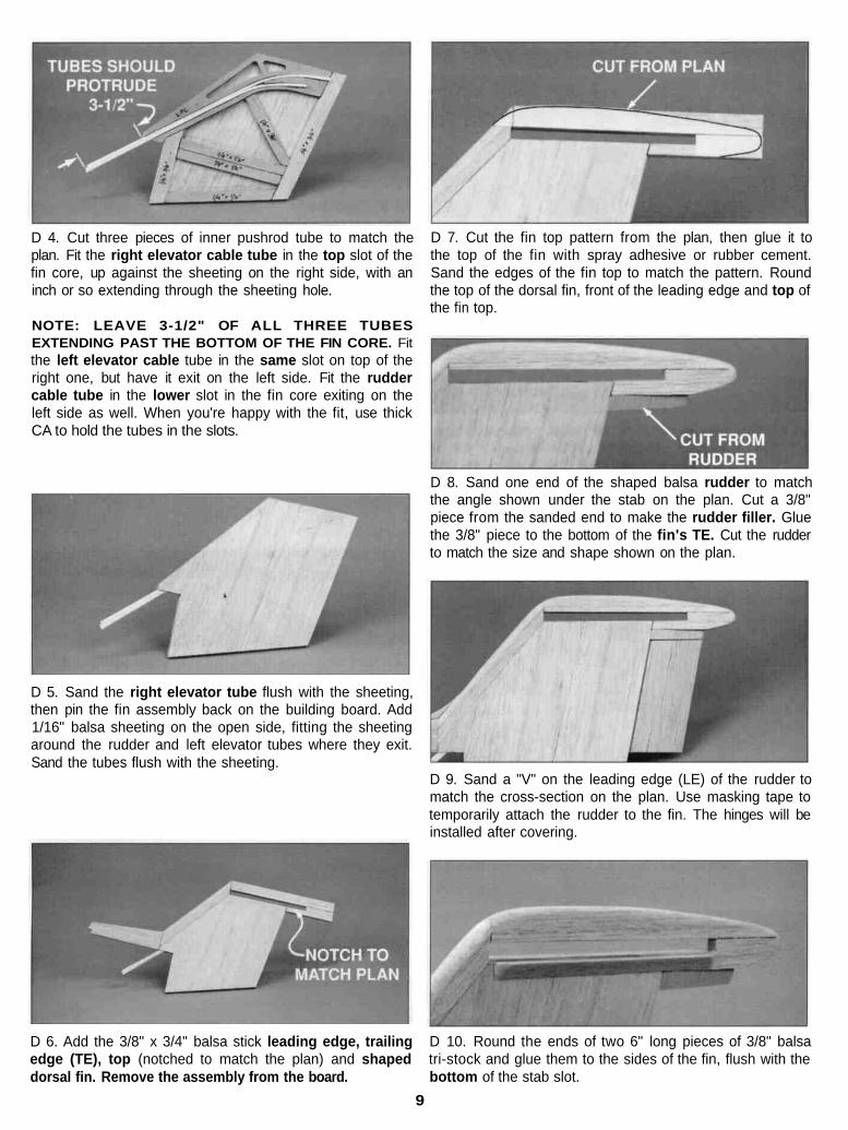
D 4. Cut three pieces of inner pushrod tube to match theplan. Fit the right elevator cable tube in the top slot of thefin core, up against the sheeting on the right side, with aninch or so extending through the sheeting hole.
NOTE: LEAVE 3-1/2" OF ALL THREE TUBESEXTENDING PAST THE BOTTOM OF THE FIN CORE. Fitthe left elevator cable tube in the same slot on top of theright one, but have it exit on the left side. Fit the ruddercable tube in the lower slot in the fin core exiting on theleft side as well. When you're happy with the fit, use thickCA to hold the tubes in the slots.
D 7. Cut the fin top pattern from the plan, then glue it tothe top of the fin with spray adhesive or rubber cement.Sand the edges of the fin top to match the pattern. Roundthe top of the dorsal fin, front of the leading edge and top ofthe fin top.
D 5. Sand the right elevator tube flush with the sheeting,then pin the fin assembly back on the building board. Add1/16" balsa sheeting on the open side, fitting the sheetingaround the rudder and left elevator tubes where they exit.Sand the tubes flush with the sheeting.
D 8. Sand one end of the shaped balsa rudder to matchthe angle shown under the stab on the plan. Cut a 3/8"piece from the sanded end to make the rudder filler. Gluethe 3/8" piece to the bottom of the fin's TE. Cut the rudderto match the size and shape shown on the plan.
D 9. Sand a "V" on the leading edge (LE) of the rudder tomatch the cross-section on the plan. Use masking tape totemporarily attach the rudder to the fin. The hinges will beinstalled after covering.
D 6. Add the 3/8" x 3/4" balsa stick leading edge, trailingedge (TE), top (notched to match the plan) and shapeddorsal fin. Remove the assembly from the board.
D 10. Round the ends of two 6" long pieces of 3/8" balsatri-stock and glue them to the sides of the fin, flush with thebottom of the stab slot.
9
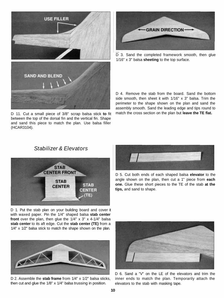
D 11. Cut a small piece of 3/8" scrap balsa stick to fitbetween the top of the dorsal fin and the vertical fin. Shapeand sand this piece to match the plan. Use balsa filler(HCAR3104).
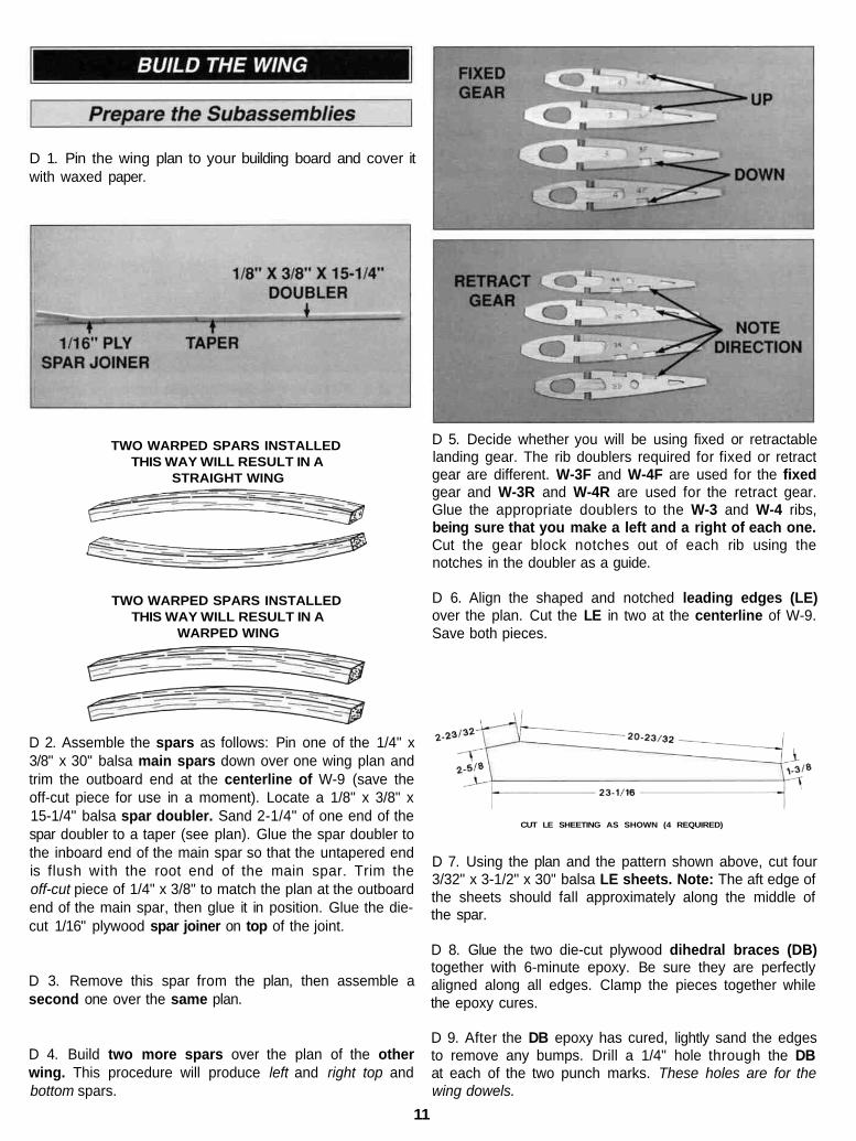
D 3. Sand the completed framework smooth, then glue1/16" x 3" balsa sheeting to the top surface.
D 4. Remove the stab from the board. Sand the bottomside smooth, then sheet it with 1/16" x 3" balsa. Trim theperimeter to the shape shown on the plan and sand theassembly smooth. Sand the leading edge and tips round tomatch the cross section on the plan but leave the TE flat.
Stabilizer & Elevators
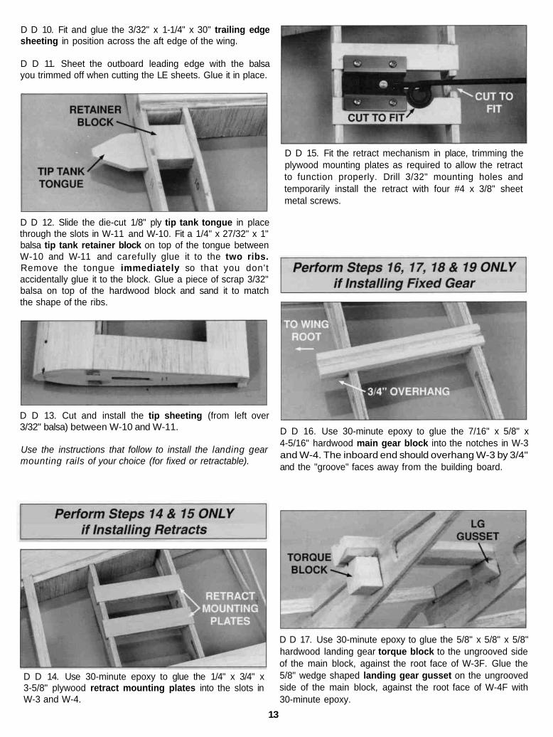
D 5. Cut both ends of each shaped balsa elevator to theangle shown on the plan, then cut a 1" piece from eachone. Glue these short pieces to the TE of the stab at thetips, and sand to shape.
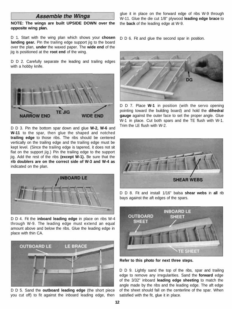
D 1. Put the stab plan on your building board and cover itwith waxed paper. Pin the 1/4" shaped balsa stab centerfront over the plan, then glue the 1/4" x 3" x 4-1/4" balsastab center to its aft edge. Cut the stab center (TE) from a1/4" x 1/2" balsa stick to match the shape shown on the plan.
D 2. Assemble the stab frame from 1/4" x 1/2" balsa sticks,then cut and glue the 1/8" x 1/4" balsa trussing in position.
D 6. Sand a "V" on the LE of the elevators and trim theinner ends to match the plan. Temporarily attach theelevators to the stab with masking tape.
10
D 1. Pin the wing plan to your building board and cover itwith waxed paper.
TWO WARPED SPARS INSTALLEDTHIS WAY WILL RESULT IN A
STRAIGHT WING
TWO WARPED SPARS INSTALLEDTHIS WAY WILL RESULT IN A
WARPED WING
D 5. Decide whether you will be using fixed or retractablelanding gear. The rib doublers required for fixed or retractgear are different. W-3F and W-4F are used for the fixedgear and W-3R and W-4R are used for the retract gear.Glue the appropriate doublers to the W-3 and W-4 ribs,being sure that you make a left and a right of each one.Cut the gear block notches out of each rib using thenotches in the doubler as a guide.
D 6. Align the shaped and notched leading edges (LE)over the plan. Cut the LE in two at the centerline of W-9.Save both pieces.
D 2. Assemble the spars as follows: Pin one of the 1/4" x3/8" x 30" balsa main spars down over one wing plan andtrim the outboard end at the centerline of W-9 (save theoff-cut piece for use in a moment). Locate a 1/8" x 3/8" x15-1/4" balsa spar doubler. Sand 2-1/4" of one end of thespar doubler to a taper (see plan). Glue the spar doubler tothe inboard end of the main spar so that the untapered endis flush with the root end of the main spar. Trim theoff-cut piece of 1/4" x 3/8" to match the plan at the outboardend of the main spar, then glue it in position. Glue the die-cut 1/16" plywood spar joiner on top of the joint.
D 3. Remove this spar from the plan, then assemble asecond one over the same plan.
D 4. Build two more spars over the plan of the otherwing. This procedure will produce left and right top andbottom spars.
CUT LE SHEETING AS SHOWN (4 REQUIRED)
D 7. Using the plan and the pattern shown above, cut four3/32" x 3-1/2" x 30" balsa LE sheets. Note: The aft edge ofthe sheets should fall approximately along the middle ofthe spar.
D 8. Glue the two die-cut plywood dihedral braces (DB)together with 6-minute epoxy. Be sure they are perfectlyaligned along all edges. Clamp the pieces together whilethe epoxy cures.
D 9. After the DB epoxy has cured, lightly sand the edgesto remove any bumps. Drill a 1/4" hole through the DBat each of the two punch marks. These holes are for thewing dowels.
11
NOTE: The wings are built UPSIDE DOWN over theopposite wing plan.
D 1. Start with the wing plan which shows your chosenlanding gear. Pin the trailing edge support jig to the boardover the plan, under the waxed paper. The wide end of thejig is positioned at the root end of the wing.
D D 2. Carefully separate the leading and trailing edgeswith a hobby knife.
D D 3. Pin the bottom spar down and glue W-2, W-6 andW-11 to the spar, then glue the shaped and notchedtrailing edge to those ribs. The ribs should be centeredvertically on the trailing edge and the trailing edge must bekept level. (Since the trailing edge is tapered, it does not sitflat on the support jig.) Pin the trailing edge to the supportjig. Add the rest of the ribs (except W-1). Be sure that therib doublers are on the correct side of W-3 and W-4 asindicated on the plan.
D D 4. Fit the inboard leading edge in place on ribs W-4through W-9. The leading edge must extend an equalamount above and below the ribs. Glue the leading edge inplace with thin CA.
D D 5. Sand the outboard leading edge (the short pieceyou cut off) to fit against the inboard leading edge, then
glue it in place on the forward edge of ribs W-9 throughW-11. Glue the die cut 1/8" plywood leading edge brace tothe back of the leading edge at W-9.
D D 6. Fit and glue the second spar in position.
D D 7. Place W-1 in position (with the servo openingpointing toward the building board) and hold the dihedralgauge against the outer face to set the proper angle. GlueW-1 in place. Cut both spars and the TE flush with W-1.Trim the LE flush with W-2.
D D 8. Fit and install 1/16" balsa shear webs in all ribbays against the aft edges of the spars.
Refer to this photo for next three steps.
D D 9. Lightly sand the top of the ribs, spar and trailingedge to remove any irregularities. Sand the forward edgeof the 3/32" inboard leading edge sheeting to match theangle made by the ribs and the leading edge. The aft edgeof the sheet should fall on the centerline of the spar. Whensatisfied with the fit, glue it in place.
12
D D 10. Fit and glue the 3/32" x 1-1/4" x 30" trailing edgesheeting in position across the aft edge of the wing.
D D 11. Sheet the outboard leading edge with the balsayou trimmed off when cutting the LE sheets. Glue it in place.
D D 15. Fit the retract mechanism in place, trimming theplywood mounting plates as required to allow the retractto function properly. Drill 3/32" mounting holes andtemporarily install the retract with four #4 x 3/8" sheetmetal screws.
D D 12. Slide the die-cut 1/8" ply tip tank tongue in placethrough the slots in W-11 and W-10. Fit a 1/4" x 27/32" x 1"balsa tip tank retainer block on top of the tongue betweenW-10 and W-11 and carefully glue it to the two ribs.Remove the tongue immediately so that you don'taccidentally glue it to the block. Glue a piece of scrap 3/32"balsa on top of the hardwood block and sand it to matchthe shape of the ribs.
D D 13. Cut and install the tip sheeting (from left over3/32" balsa) between W-10 and W-11.
Use the instructions that follow to install the landing gearmounting rails of your choice (for fixed or retractable).
D D 16. Use 30-minute epoxy to glue the 7/16" x 5/8" x4-5/16" hardwood main gear block into the notches in W-3and W-4. The inboard end should overhang W-3 by 3/4"and the "groove" faces away from the building board.
D D 14. Use 30-minute epoxy to glue the 1/4" x 3/4" x3-5/8" plywood retract mounting plates into the slots inW-3 and W-4.
D D 17. Use 30-minute epoxy to glue the 5/8" x 5/8" x 5/8"hardwood landing gear torque block to the ungrooved sideof the main block, against the root face of W-3F. Glue the5/8" wedge shaped landing gear gusset on the ungroovedside of the main block, against the root face of W-4F with30-minute epoxy.
13
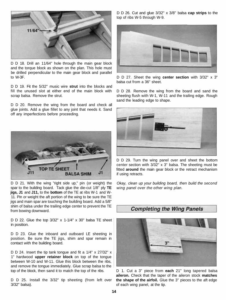
D D 18. Drill an 11/64" hole through the main gear blockand the torque block as shown on the plan. This hole mustbe drilled perpendicular to the main gear block and parallelto W-3F.
D D 19. Fit the 5/32" music wire strut into the blocks andfill the unused slot at either end of the main block withscrap balsa. Remove the strut.
D D 20. Remove the wing from the board and check allglue joints. Add a glue fillet to any joint that needs it. Sandoff any imperfections before proceeding.
D D 21. With the wing "right side up," pin (or weight) thespar to the building board. Tack glue the die-cut 1/8" ply TEjigs, J1 and J11, to the bottom of the TE at ribs W-1 and W-11. Pin or weight the aft portion of the wing to be sure the TEjigs and main spar are touching the building board. Add a 5/8"shim of balsa under the trailing edge center to prevent the TEfrom bowing downward.
D D 22. Glue the top 3/32" x 1-1/4" x 30" balsa TE sheetin position.
D D 23. Glue the inboard and outboard LE sheeting inposition. Be sure the TE jigs, shim and spar remain incontact with the building board.
D D 24. Insert the tip tank tongue and fit a 1/4" x 27/32" x1" hardwood upper retainer block on top of the tonguebetween W-10 and W-11. Glue this block between the ribs,and remove the tongue immediately. Glue scrap balsa to thetop of the block, then sand it to match the top of the ribs.
D D 25. Install the 3/32" tip sheeting (from left over3/32" balsa).
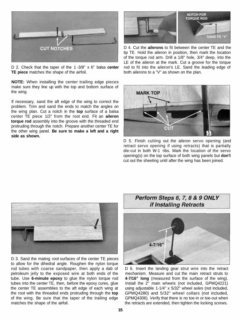
D D 26. Cut and glue 3/32" x 3/8" balsa cap strips to thetop of ribs W-5 through W-9.
D D 27. Sheet the wing center section with 3/32" x 3"balsa cut from a 36" sheet.
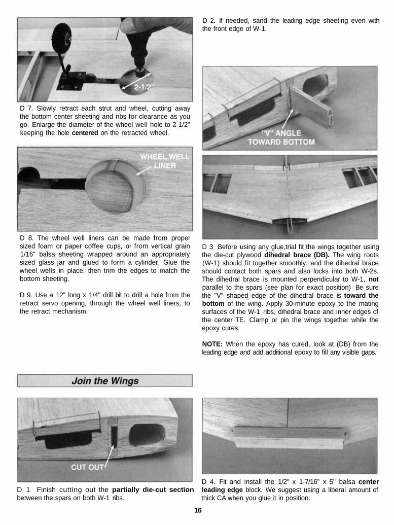
D D 28. Remove the wing from the board and sand thesheeting flush with W-1, W-11 and the trailing edge. Roughsand the leading edge to shape.
D D 29. Turn the wing panel over and sheet the bottomcenter section with 3/32" x 3" balsa. The sheeting must befitted around the main gear block or the retract mechanismif using retracts.
Okay, clean up your building board, then build the secondwing panel over the other wing plan.
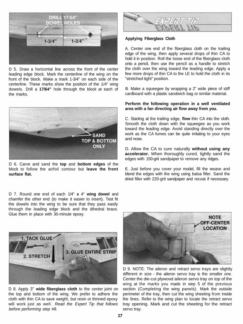
D 1. Cut a 3" piece from each 21" long tapered balsaaileron. Check that the taper of the aileron stock matchesthe shape of the airfoil. Glue the 3" pieces to the aft edgeof each wing panel, at the tip.
14
D 2. Check that the taper of the 1 -3/8" x 6" balsa centerTE piece matches the shape of the airfoil.
NOTE: When installing the center trailing edge piecesmake sure they line up with the top and bottom surface ofthe wing.
If necessary, sand the aft edge of the wing to correct theproblem. Trim and sand the ends to match the angles onthe wing plan. Cut a notch in the top surface of a balsacenter TE piece 1/2" from the root end. Fit an ailerontorque rod assembly into the groove with the threaded endprotruding through the notch. Prepare another center TE forthe other wing panel. Be sure to make a left and a rightside as shown.
D 4. Cut the ailerons to fit between the center TE and thetip TE. Hold the aileron in position, then mark the locationof the torque rod arm. Drill a 1/8" hole, 3/4" deep, into theLE of the aileron at the mark. Cut a groove for the torquerod to fit into the aileron's LE. Sand the leading edge ofboth ailerons to a "V" as shown on the plan.
D 5. Finish cutting out the aileron servo opening (andretract servo opening if using retracts) that is partiallydie-cut in both W-1 ribs. Mark the location of the servoopening(s) on the top surface of both wing panels but don'tcut out the sheeting until after the wing has been joined.
D 3. Sand the mating root surfaces of the center TE piecesto allow for the dihedral angle. Roughen the nylon torquerod tubes with coarse sandpaper, then apply a dab ofpetroleum jelly to the exposed wire at both ends of thetube. Use 6-minute epoxy to glue the nylon torque rodtubes into the center TE, then, before the epoxy cures, gluethe center TE assemblies to the aft edge of each wing atthe root with the threaded ends protruding through the topof the wing. Be sure that the taper of the trailing edgematches the shape of the airfoil.
D 6. Insert the landing gear strut wire into the retractmechanism. Measure and cut the main retract struts to4-7/16" long (measured from the surface of the wing).Install the 2" main wheels (not included, GPMQ4221)using adjustable 1-1/4" x 5/32" wheel axles (not included,GPMQ4280) and 5/32" wheel collars (not included,GPMQ4306). Verify that there is no toe-in or toe-out whenthe retracts are extended, then tighten the locking screws.
15
D 7. Slowly retract each strut and wheel, cutting awaythe bottom center sheeting and ribs for clearance as yougo. Enlarge the diameter of the wheel well hole to 2-1/2"keeping the hole centered on the retracted wheel.
D 8. The wheel well liners can be made from propersized foam or paper coffee cups, or from vertical grain1/16" balsa sheeting wrapped around an appropriatelysized glass jar and glued to form a cylinder. Glue thewheel wells in place, then trim the edges to match thebottom sheeting.
D 9. Use a 12" long x 1/4" drill bit to drill a hole from theretract servo opening, through the wheel well liners, tothe retract mechanism.
D 2. If needed, sand the leading edge sheeting even withthe front edge of W-1.
D 3 Before using any glue,trial fit the wings together usingthe die-cut plywood dihedral brace (DB). The wing roots(W-1) should fit together smoothly, and the dihedral braceshould contact both spars and also locks into both W-2s.The dihedral brace is mounted perpendicular to W-1, notparallel to the spars (see plan for exact position) Be surethe "V" shaped edge of the dihedral brace is toward thebottom of the wing. Apply 30-minute epoxy to the matingsurfaces of the W-1 ribs, dihedral brace and inner edges ofthe center TE. Clamp or pin the wings together while theepoxy cures.
NOTE: When the epoxy has cured, look at (DB) from theleading edge and add additional epoxy to fill any visible gaps.
D 1 Finish cutting out the partially die-cut sectionbetween the spars on both W-1 ribs.
D 4. Fit and install the 1/2" x 1-7/16" x 5" balsa centerleading edge block. We suggest using a liberal amount ofthick CA when you glue it in position.
16
D 5. Draw a horizontal line across the front of the centerleading edge block. Mark the centerline of the wing on thefront of the block. Make a mark 1-3/4" on each side of thecenterline. These marks show the position of the 1/4" wingdowels. Drill a 17/64" hole through the block at each ofthe marks.
D 6. Carve and sand the top and bottom edges of theblock to follow the airfoil contour but leave the frontsurface flat.
Applying Fiberglass Cloth
A. Center one end of the fiberglass cloth on the trailingedge of the wing, then apply several drops of thin CA tohold it in position. Roll the loose end of the fiberglass clothonto a pencil, then use the pencil as a handle to stretchthe cloth over the wing toward the leading edge. Apply afew more drops of thin CA to the LE to hold the cloth in its"stretched tight" position.
B. Make a squeegee by wrapping a 2" wide piece of stiffcardboard with a plastic sandwich bag or similar material.
Perform the following operation in a well ventilatedarea with a fan directing air flow away from you.
C. Starting at the trailing edge, flow thin CA into the cloth.Smooth the cloth down with the squeegee as you worktoward the leading edge. Avoid standing directly over thework as the CA fumes can be quite irritating to your eyesand nose.
D. Allow the CA to cure naturally without using anyaccelerator. When thoroughly cured, lightly sand theedges with 150-grit sandpaper to remove any ridges.
E. Just before you cover your model, fill the weave andblend the edges with the wing using balsa filler. Sand thedried filler with 220-grit sandpaper and recoat if necessary.
D 7. Round one end of each 1/4" x 4" wing dowel andchamfer the other end (to make it easier to insert). Test fitthe dowels into the wing to be sure that they pass easilythrough the leading edge block and the dihedral brace.Glue them in place with 30-minute epoxy.
D 8. Apply 3" wide fiberglass cloth to the center joint onthe top and bottom of the wing. We prefer to adhere thecloth with thin CA to save weight, but resin or thinned epoxywill work just as well. Read the Expert Tip that followsbefore performing step #8.
D 9. NOTE: The aileron and retract servo trays are slightlydifferent in size - the aileron servo tray is the smaller one.Center the die-cut plywood aileron servo tray on top of thewing at the marks you made in siep 5 of the previoussection (Completing the wing panels). Mark the outsideperimeter of the tray, then cut the wing sheeting from insidethe lines. Refer to the wing plan to locate the retract servotray opening. Mark and cut the sheeting for the retractservo tray.
17
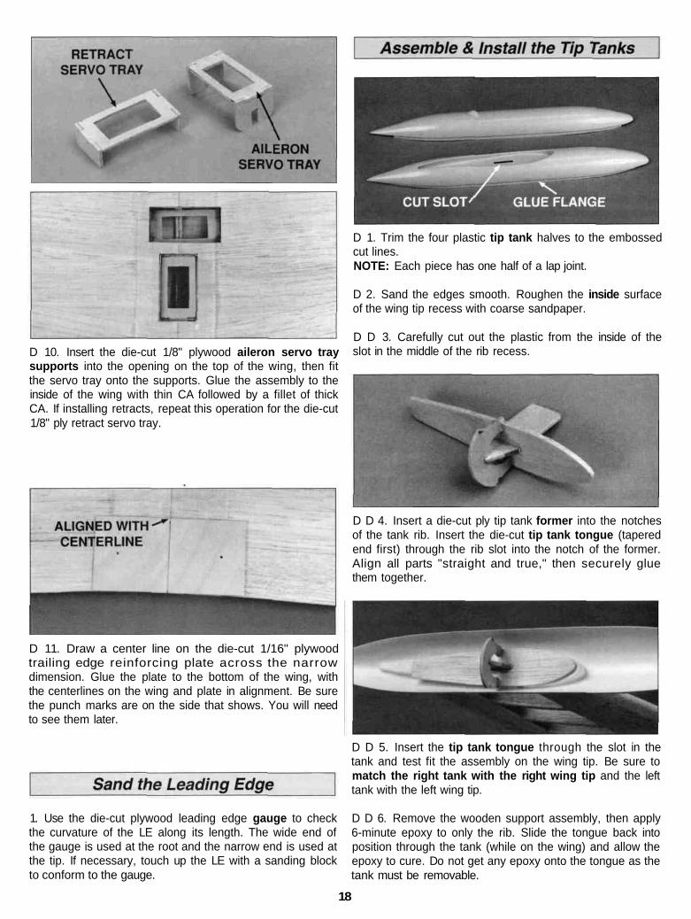
D 10. Insert the die-cut 1/8" plywood aileron servo traysupports into the opening on the top of the wing, then fitthe servo tray onto the supports. Glue the assembly to theinside of the wing with thin CA followed by a fillet of thickCA. If installing retracts, repeat this operation for the die-cut1/8" ply retract servo tray.
D 11. Draw a center line on the die-cut 1/16" plywoodtrailing edge reinforcing plate across the narrowdimension. Glue the plate to the bottom of the wing, withthe centerlines on the wing and plate in alignment. Be surethe punch marks are on the side that shows. You will needto see them later.
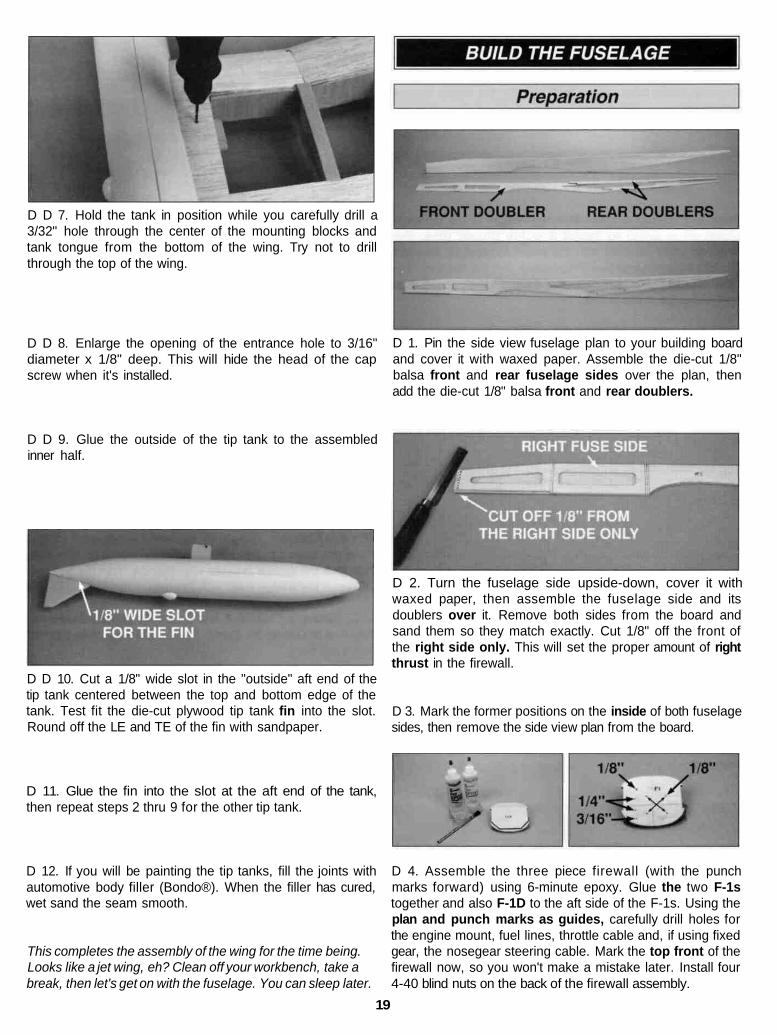
D 1. Trim the four plastic tip tank halves to the embossedcut lines.NOTE: Each piece has one half of a lap joint.
D 2. Sand the edges smooth. Roughen the inside surfaceof the wing tip recess with coarse sandpaper.
D D 3. Carefully cut out the plastic from the inside of theslot in the middle of the rib recess.
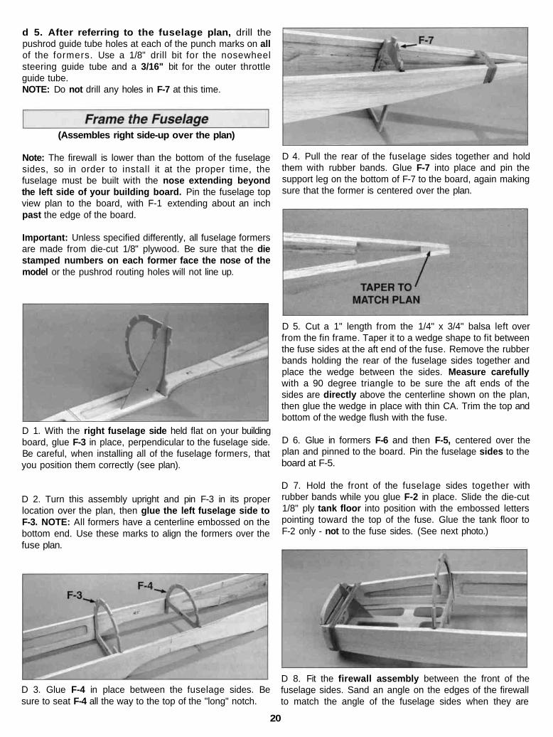
D D 4. Insert a die-cut ply tip tank former into the notchesof the tank rib. Insert the die-cut tip tank tongue (taperedend first) through the rib slot into the notch of the former.Align all parts "straight and true," then securely gluethem together.
1. Use the die-cut plywood leading edge gauge to checkthe curvature of the LE along its length. The wide end ofthe gauge is used at the root and the narrow end is used atthe tip. If necessary, touch up the LE with a sanding blockto conform to the gauge.
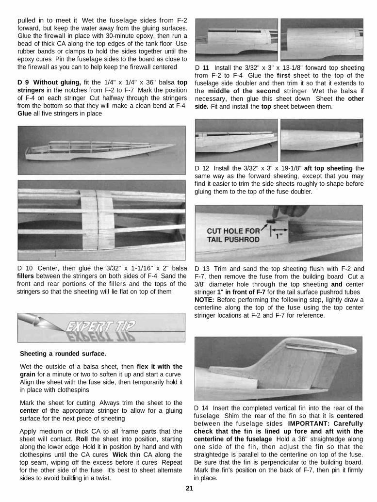
D D 5. Insert the tip tank tongue through the slot in thetank and test fit the assembly on the wing tip. Be sure tomatch the right tank with the right wing tip and the lefttank with the left wing tip.
D D 6. Remove the wooden support assembly, then apply6-minute epoxy to only the rib. Slide the tongue back intoposition through the tank (while on the wing) and allow theepoxy to cure. Do not get any epoxy onto the tongue as thetank must be removable.
18
D D 7. Hold the tank in position while you carefully drill a3/32" hole through the center of the mounting blocks andtank tongue from the bottom of the wing. Try not to drillthrough the top of the wing.
D D 8. Enlarge the opening of the entrance hole to 3/16"diameter x 1/8" deep. This will hide the head of the capscrew when it's installed.
D 1. Pin the side view fuselage plan to your building boardand cover it with waxed paper. Assemble the die-cut 1/8"balsa front and rear fuselage sides over the plan, thenadd the die-cut 1/8" balsa front and rear doublers.
D D 9. Glue the outside of the tip tank to the assembledinner half.
D 2. Turn the fuselage side upside-down, cover it withwaxed paper, then assemble the fuselage side and itsdoublers over it. Remove both sides from the board andsand them so they match exactly. Cut 1/8" off the front ofthe right side only. This will set the proper amount of rightthrust in the firewall.
D D 10. Cut a 1/8" wide slot in the "outside" aft end of thetip tank centered between the top and bottom edge of thetank. Test fit the die-cut plywood tip tank fin into the slot.Round off the LE and TE of the fin with sandpaper.
D 3. Mark the former positions on the inside of both fuselagesides, then remove the side view plan from the board.
D 11. Glue the fin into the slot at the aft end of the tank,then repeat steps 2 thru 9 for the other tip tank.
D 12. If you will be painting the tip tanks, fill the joints withautomotive body filler (Bondo®). When the filler has cured,wet sand the seam smooth.
This completes the assembly of the wing for the time being.Looks like a jet wing, eh? Clean off your workbench, take abreak, then let's get on with the fuselage. You can sleep later.
D 4. Assemble the three piece firewall (with the punchmarks forward) using 6-minute epoxy. Glue the two F-1stogether and also F-1D to the aft side of the F-1s. Using theplan and punch marks as guides, carefully drill holes forthe engine mount, fuel lines, throttle cable and, if using fixedgear, the nosegear steering cable. Mark the top front of thefirewall now, so you won't make a mistake later. Install four4-40 blind nuts on the back of the firewall assembly.
19
d 5. After referring to the fuselage plan, drill thepushrod guide tube holes at each of the punch marks on allof the formers. Use a 1/8" drill bit for the nosewheelsteering guide tube and a 3/16" bit for the outer throttleguide tube.NOTE: Do not drill any holes in F-7 at this time.
(Assembles right side-up over the plan)
Note: The firewall is lower than the bottom of the fuselagesides, so in order to install it at the proper time, thefuselage must be built with the nose extending beyondthe left side of your building board. Pin the fuselage topview plan to the board, with F-1 extending about an inchpast the edge of the board.
Important: Unless specified differently, all fuselage formersare made from die-cut 1/8" plywood. Be sure that the diestamped numbers on each former face the nose of themodel or the pushrod routing holes will not line up.
D 1. With the right fuselage side held flat on your buildingboard, glue F-3 in place, perpendicular to the fuselage side.Be careful, when installing all of the fuselage formers, thatyou position them correctly (see plan).
D 2. Turn this assembly upright and pin F-3 in its properlocation over the plan, then glue the left fuselage side toF-3. NOTE: All formers have a centerline embossed on thebottom end. Use these marks to align the formers over thefuse plan.
D 3. Glue F-4 in place between the fuselage sides. Besure to seat F-4 all the way to the top of the "long" notch.
D 4. Pull the rear of the fuselage sides together and holdthem with rubber bands. Glue F-7 into place and pin thesupport leg on the bottom of F-7 to the board, again makingsure that the former is centered over the plan.
D 5. Cut a 1" length from the 1/4" x 3/4" balsa left overfrom the fin frame. Taper it to a wedge shape to fit betweenthe fuse sides at the aft end of the fuse. Remove the rubberbands holding the rear of the fuselage sides together andplace the wedge between the sides. Measure carefullywith a 90 degree triangle to be sure the aft ends of thesides are directly above the centerline shown on the plan,then glue the wedge in place with thin CA. Trim the top andbottom of the wedge flush with the fuse.
D 6. Glue in formers F-6 and then F-5, centered over theplan and pinned to the board. Pin the fuselage sides to theboard at F-5.
D 7. Hold the front of the fuselage sides together withrubber bands while you glue F-2 in place. Slide the die-cut1/8" ply tank floor into position with the embossed letterspointing toward the top of the fuse. Glue the tank floor toF-2 only - not to the fuse sides. (See next photo.)
D 8. Fit the firewall assembly between the front of thefuselage sides. Sand an angle on the edges of the firewallto match the angle of the fuselage sides when they are
20
pulled in to meet it Wet the fuselage sides from F-2forward, but keep the water away from the gluing surfaces.Glue the firewall in place with 30-minute epoxy, then run abead of thick CA along the top edges of the tank floor Userubber bands or clamps to hold the sides together until theepoxy cures Pin the fuselage sides to the board as close tothe firewall as you can to help keep the firewall centered
D 9 Without gluing, fit the 1/4" x 1/4" x 36" balsa topstringers in the notches from F-2 to F-7 Mark the positionof F-4 on each stringer Cut halfway through the stringersfrom the bottom so that they will make a clean bend at F-4Glue all five stringers in place
D 11 Install the 3/32" x 3" x 13-1/8" forward top sheetingfrom F-2 to F-4 Glue the first sheet to the top of thefuselage side doubler and then trim it so that it extends tothe middle of the second stringer Wet the balsa ifnecessary, then glue this sheet down Sheet the otherside. Fit and install the top sheet between them.
D 12 Install the 3/32" x 3" x 19-1/8" aft top sheeting thesame way as the forward sheeting, except that you mayfind it easier to trim the side sheets roughly to shape beforegluing them to the top of the fuse doubler.
D 10 Center, then glue the 3/32" x 1-1/16" x 2" balsafillers between the stringers on both sides of F-4 Sand thefront and rear portions of the fillers and the tops of thestringers so that the sheeting will lie flat on top of them
Sheeting a rounded surface.
Wet the outside of a balsa sheet, then flex it with thegrain for a minute or two to soften it up and start a curveAlign the sheet with the fuse side, then temporarily hold itin place with clothespins
Mark the sheet for cutting Always trim the sheet to thecenter of the appropriate stringer to allow for a gluingsurface for the next piece of sheeting
Apply medium or thick CA to all frame parts that thesheet will contact. Roll the sheet into position, startingalong the lower edge Hold it in position by hand and withclothespins until the CA cures Wick thin CA along thetop seam, wiping off the excess before it cures Repeatfor the other side of the fuse It's best to sheet alternatesides to avoid building in a twist.
D 13 Trim and sand the top sheeting flush with F-2 andF-7, then remove the fuse from the building board Cut a3/8" diameter hole through the top sheeting and centerstringer 1" in front of F-7 for the tail surface pushrod tubesNOTE: Before performing the following step, lightly draw acenterline along the top of the fuse using the top centerstringer locations at F-2 and F-7 for reference.
D 14 Insert the completed vertical fin into the rear of thefuselage Shim the rear of the fin so that it is centeredbetween the fuselage sides IMPORTANT: Carefullycheck that the fin is lined up fore and aft with thecenterline of the fuselage Hold a 36" straightedge alongone side of the fin, then adjust the f in so that thestraightedge is parallel to the centerline on top of the fuse.Be sure that the fin is perpendicular to the building board.Mark the fin's position on the back of F-7, then pin it firmlyin place.
21
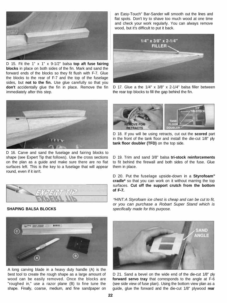
D 15. Fit the 1" x 1" x 9-1/2" balsa top aft fuse fairingblocks in place on both sides of the fin. Mark and sand theforward ends of the blocks so they fit flush with F-7. Gluethe blocks to the rear of F-7 and the top of the fuselagesides, but not to the fin. Use glue carefully so that youdon't accidentally glue the fin in place. Remove the finimmediately after this step.
an Easy-Touch" Bar-Sander will smooth out the lines andflat spots. Don't try to shave too much wood at one timeand check your work regularly. You can always removewood, but it's difficult to put it back.
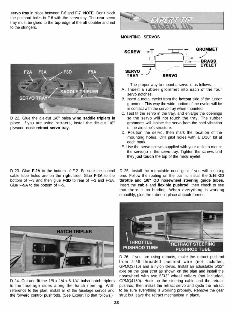
D 17. Glue a the 1/4" x 3/8" x 2-1/4" balsa filler betweenthe rear top blocks to fill the gap behind the fin.
D 16. Carve and sand the fuselage and fairing blocks toshape (see Expert Tip that follows). Use the cross sectionson the plan as a guide and make sure there are no flatsurfaces left. This is the key to a fuselage that will appearround, even if it isn't.
SHAPING BALSA BLOCKS
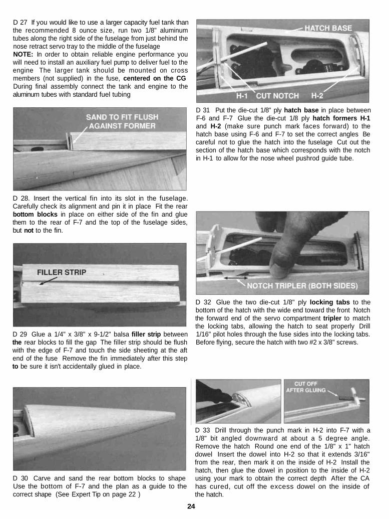
D 18. If you will be using retracts, cut out the scored partin the front of the tank floor and install the die-cut 1/8" plytank floor doubler (TFD) on the top side.
D 19. Trim and sand 3/8" balsa tri-stock reinforcementsto fit behind the firewall and both sides of the fuse. Gluethem in place.
D 20. Put the fuselage upside-down in a Styrofoam"cradle* so that you can work on it without marring the topsurfaces. Cut off the support crutch from the bottomof F-7.
*HINT:A Styrofoam ice chest is cheap and can be cut to fit,or you can purchase a Robart Super Stand which isspecifically made for this purpose.
A long carving blade in a heavy duty handle (A) is thebest tool to create the rough shape as a large amount ofwood can be easily removed. Once the blocks are"roughed in," use a razor plane (B) to fine tune theshape. Finally, coarse, medium, and fine sandpaper on
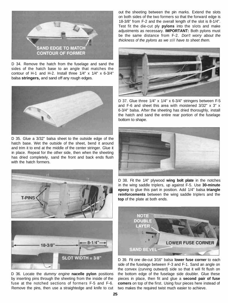
D 21. Sand a bevel on the wide end of the die-cut 1/8" plyforward servo tray that corresponds to the angle at F-6(see side view of fuse plan). Using the bottom view plan as aguide, glue the forward and the die-cut 1/8" plywood rear
22
servo tray in place between F-6 and F-7. NOTE: Don't blockthe pushrod holes in F-6 with the servo tray. The rear servotray must be glued to the top edge of the aft doubler and notto the stringers.
MOUNTING SERVOS
D 22. Glue the die-cut 1/8" balsa wing saddle triplers inplace. If you are using retracts, install the die-cut 1/8"plywood nose retract servo tray.
The proper way to mount a servo is as follows:A. Insert a rubber grommet into each of the four
servo notches.B. Insert a metal eyelet from the bottom side of the rubber
grommet. This way the wide portion of the eyelet will bein contact with the servo tray when mounted.
C. Test fit the servo in the tray, and enlarge the openingsso the servo will not touch the tray. The rubbergrommets will isolate the servo from the hard vibrationof the airplane's structure.
D. Position the servo, then mark the location of themounting holes. Drill pilot holes with a 1/16" bit ateach mark.
E. Use the servo screws supplied with your radio to mountthe servo(s) in the servo tray. Tighten the screws untilthey just touch the top of the metal eyelet.
D 23. Glue F-2A to the bottom of F-2. Be sure the controlcable tube holes are on the right side. Glue F-3A to thebottom of F-3 and then glue F-3D to rear of F-3 and F-3A.Glue F-5A to the bottom of F-5.
D 25. Install the retractable nose gear if you will be usingone. Follow the routing on the plan to install the 3/16 ODthrottle and 1/8" OD nosewheel steering guide tubes.Insert the cable and flexible pushrod, then check to seethat there is no binding. When everything is workingsmoothly, glue the tubes in place at each former.
D 24. Cut and fit the 1/8 x 1/4 x 6-1/4" balsa hatch triplersto the fuselage sides along the hatch opening. Withreference to the plan, install all of the fuselage servos andthe forward control pushrods. (See Expert Tip that follows.)
D 26. If you are using retracts, make the retract pushrodfrom 2-56 threaded pushrod wire (not included,GPMQ3716) and a nylon clevis. Install an adjustable 5/32"axle on the gear strut as shown on the plan and install thenosewheel with two 5/32" wheel collars (not included,GPMQ4150). Hook up the steering cable and the retractpushrod, then install the retract servo and cycle the retractto be sure everything is working properly. Remove the gearstrut but leave the retract mechanism in place.
23
D 27 If you would like to use a larger capacity fuel tank thanthe recommended 8 ounce size, run two 1/8" aluminumtubes along the right side of the fuselage from just behind thenose retract servo tray to the middle of the fuselageNOTE: In order to obtain reliable engine performance youwill need to install an auxiliary fuel pump to deliver fuel to theengine The larger tank should be mounted on crossmembers (not supplied) in the fuse, centered on the CGDuring final assembly connect the tank and engine to thealuminum tubes with standard fuel tubing
D 31 Put the die-cut 1/8" ply hatch base in place betweenF-6 and F-7 Glue the die-cut 1/8 ply hatch formers H-1and H-2 (make sure punch mark faces forward) to thehatch base using F-6 and F-7 to set the correct angles Becareful not to glue the hatch into the fuselage Cut out thesection of the hatch base which corresponds with the notchin H-1 to allow for the nose wheel pushrod guide tube.
D 28. Insert the vertical fin into its slot in the fuselage.Carefully check its alignment and pin it in place Fit the rearbottom blocks in place on either side of the fin and gluethem to the rear of F-7 and the top of the fuselage sides,but not to the fin.
D 29 Glue a 1/4" x 3/8" x 9-1/2" balsa filler strip betweenthe rear blocks to fill the gap The filler strip should be flushwith the edge of F-7 and touch the side sheeting at the aftend of the fuse Remove the fin immediately after this stepto be sure it isn't accidentally glued in place.
D 32 Glue the two die-cut 1/8" ply locking tabs to thebottom of the hatch with the wide end toward the front Notchthe forward end of the servo compartment tripler to matchthe locking tabs, allowing the hatch to seat properly Drill1/16" pilot holes through the fuse sides into the locking tabs.Before flying, secure the hatch with two #2 x 3/8" screws.
D 30 Carve and sand the rear bottom blocks to shapeUse the bottom of F-7 and the plan as a guide to thecorrect shape (See Expert Tip on page 22 )
D 33 Drill through the punch mark in H-2 into F-7 with a1/8" bit angled downward at about a 5 degree angle.Remove the hatch Round one end of the 1/8" x 1" hatchdowel Insert the dowel into H-2 so that it extends 3/16"from the rear, then mark it on the inside of H-2 Install thehatch, then glue the dowel in position to the inside of H-2using your mark to obtain the correct depth After the CAhas cured, cut off the excess dowel on the inside ofthe hatch.
24
D 34. Remove the hatch from the fuselage and sand thesides of the hatch base to an angle that matches thecontour of H-1 and H-2. Install three 1/4" x 1/4" x 6-3/4"balsa stringers, and sand off any rough edges.
D 35. Glue a 3/32" balsa sheet to the outside edge of thehatch base. Wet the outside of the sheet, bend it aroundand trim it to end at the middle of the center stringer. Glue itin place. Repeat for the other side, then when the sheetinghas dried completely, sand the front and back ends flushwith the hatch formers.
D 36. Locate the dummy engine nacelle pylon positionsby inserting pins through the sheeting from the inside of thefuse at the notched sections of formers F-5 and F-6.Remove the pins, then use a straightedge and knife to cut
out the sheeting between the pin marks. Extend the slotson both sides of the two formers so that the forward edge is18-3/8" from F-2 and the overall length of the slot is 8-1/4".Test fit the die-cut ply pylons into the slots and makeadjustments as necessary. IMPORTANT: Both pylons mustbe the same distance from F-2. Don't worry about thethickness of the pylons as we s t i l l have to sheet them.
D 37. Glue three 1/4" x 1/4" x 6-3/4" stringers between F-5and F-6 and sheet this area with moistened 3/32" x 3" x6-3/4" balsa. After the sheeting has dried thoroughly, installthe hatch and sand the entire rear portion of the fuselagebottom to shape.
D 38. Fit the 1/4" plywood wing bolt plate in the notchesin the wing saddle triplers, up against F-5. Use 30-minuteepoxy to glue this part in position. Add 1/4" balsa trianglereinforcements between the wing saddle triplers and thetop of the plate at both ends.
D 39. Fit one die-cut 3/16" balsa lower fuse corner to eachside of the fuselage between F-3 and F-1. Sand an angle onthe convex (curving outward) side so that it will fit flush onthe bottom edge of the fuselage side doubler. Glue thesepieces in place, then fit and glue a second pair of fusecomers on top of the first. Using four pieces here instead oftwo makes the required twist much easier to achieve.
25

D 40. Remove the retract mechanism. Trim and sand thetops of the F-8s flush with the top of F-1 D, F-2A and F-3A,then glue the 1/2" x 4" x 13" balsa front bottom block inplace. If you are using retracts, cut a clearance hole for theretract mechanism in the block. HINT: To locate the positionof the retract mechanism, push a sharpened piece of wirethrough the retract screw holes in the tank floor out throughthe bottom of the block. Align the retract mechanism overthe holes, then mark its shape. Carve off the overhangingportions of the fuse bottom and roughly create therounded shape.
D 41. If you are using retracts, reinstall the retract unit,axle and wheel. Slowly retract the gear while you cut awaythe portions of the bottom block which interfere. A templatehas been provided on the fuse plan for reference. Cycle theretract a few times to be sure that everything workscorrectly, then remove the retract assembly.
bars were attached must be smooth to allow the mounthalves to fit together. Trim the flashing from any roughedges if necessary. Assemble the mount halves as shown.
D 2. Temporarily install the engine mount on the firewallusing four #4 flat washers and four 4-40 x 1" machinescrews. Don't tighten the screws completely until after theengine has been positioned.
D 3. Position the engine on the engine mount. Slide theengine mount halves apart until the engine mounting lugswill sit flat on the rails. Adjust the mount up and down untilthe tic marks on the mount are centered on the horizontalreference line on the firewall. After adjusting the mount,tighten the 4-40 screws to hold it firmly in position.
D 4. Position the engine so that the backplate of a spinnerwill be 4" (102mm) in front of the firewall. Carefully markthe engine mounting holes on the rails with a sharpenedpiece of wire or a pencil lead.
D 5. Remove the engine and engine mount from the fuse.Use a centerpunch or sharpened nail to "dimple" the markson the rails, then drill a 7/64" hole through the rails at eachpunch mark. If you have access to a drill press, this is thebest tool for the job. However, if you are using a hand heldelectric drill, try to keep the bit perpendicular to the rails.Test fit the engine but don't screw it permanently in positionjust yet.
The Great Planes adjustable engine mount is simple andconvenient to use. It may be used to mount most .20 - .40two-stroke and .26 - .48 four-stroke engines. Nose gearbearings for 5/32" diameter wire are incorporated in themount.
REMOVE
D 1. Cut or break the "spreader bar" from each mount half.Carefully trim any extra material left by the spreader barfrom each mount half as the surface where the spreader
D 1. Protect the edges of the fuse and formers with waxedpaper, then fit the die-cut 1/8" ply canopy base between F-1 and F-2. Glue the die-cut 1/8" ply C-1 and C-2 to thecanopy base using F-1 and F-2 to set the proper angles. Becareful not to glue the canopy base to the fuselage.
26
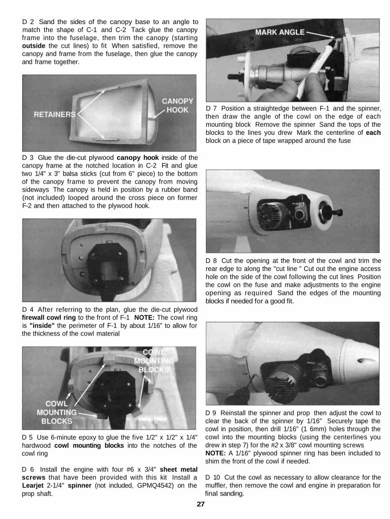
D 2 Sand the sides of the canopy base to an angle tomatch the shape of C-1 and C-2 Tack glue the canopyframe into the fuselage, then trim the canopy (startingoutside the cut lines) to fit When satisfied, remove thecanopy and frame from the fuselage, then glue the canopyand frame together.
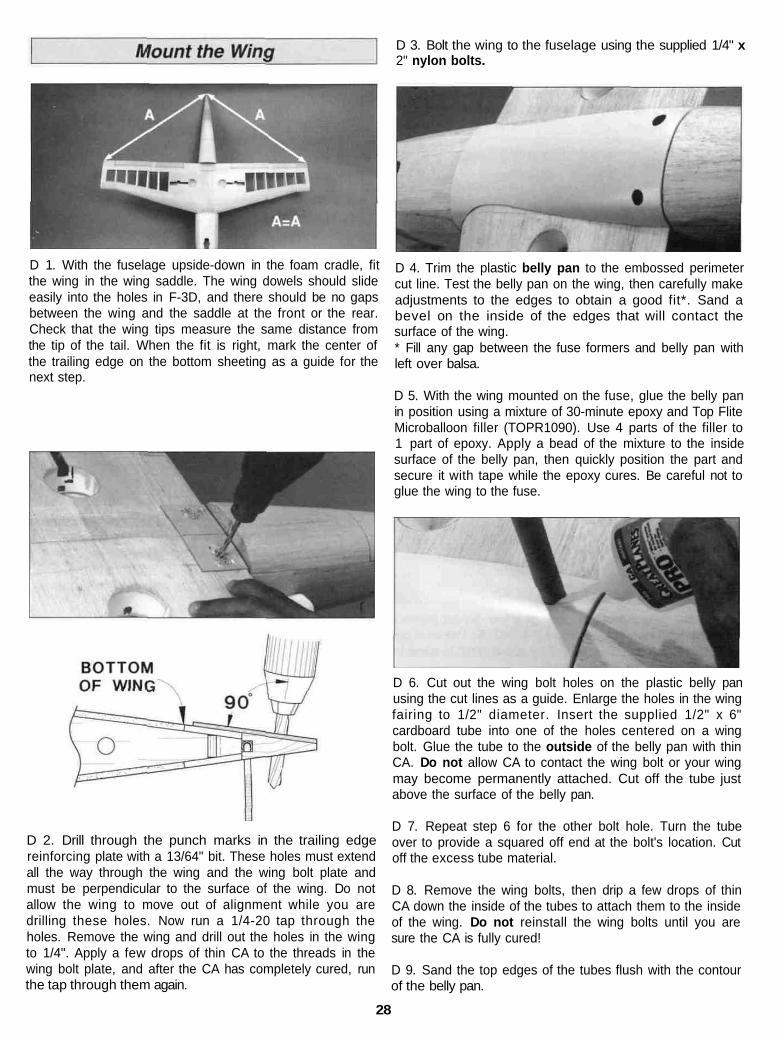
D 7 Position a straightedge between F-1 and the spinner,then draw the angle of the cowl on the edge of eachmounting block Remove the spinner Sand the tops of theblocks to the lines you drew Mark the centerline of eachblock on a piece of tape wrapped around the fuse
D 3 Glue the die-cut plywood canopy hook inside of thecanopy frame at the notched location in C-2 Fit and gluetwo 1/4" x 3" balsa sticks (cut from 6" piece) to the bottomof the canopy frame to prevent the canopy from movingsideways The canopy is held in position by a rubber band(not included) looped around the cross piece on formerF-2 and then attached to the plywood hook.
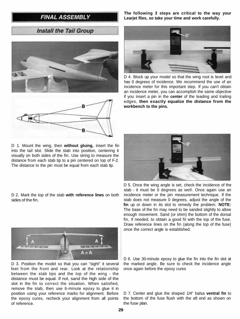
D 8 Cut the opening at the front of the cowl and trim therear edge to along the "cut line " Cut out the engine accesshole on the side of the cowl following the cut lines Positionthe cowl on the fuse and make adjustments to the engineopening as required Sand the edges of the mountingblocks if needed for a good fit.
D 4 After referring to the plan, glue the die-cut plywoodfirewall cowl ring to the front of F-1 NOTE: The cowl ringis "inside" the perimeter of F-1 by about 1/16" to allow forthe thickness of the cowl material
D 5 Use 6-minute epoxy to glue the five 1/2" x 1/2" x 1/4"hardwood cowl mounting blocks into the notches of thecowl ring
D 6 Install the engine with four #6 x 3/4" sheet metalscrews that have been provided with this kit Install aLearjet 2-1/4" spinner (not included, GPMQ4542) on theprop shaft.
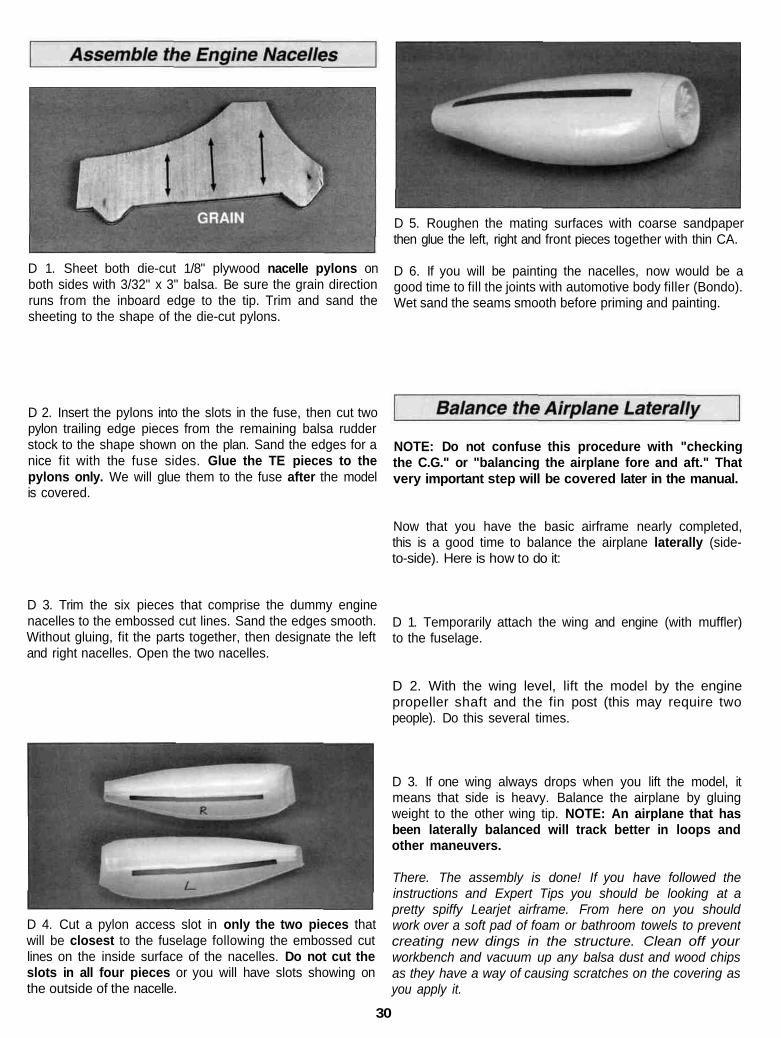
D 9 Reinstall the spinner and prop then adjust the cowl toclear the back of the spinner by 1/16" Securely tape thecowl in position, then drill 1/16" (1 6mm) holes through thecowl into the mounting blocks (using the centerlines youdrew in step 7) for the #2 x 3/8" cowl mounting screwsNOTE: A 1/16" plywood spinner ring has been included toshim the front of the cowl if needed.
D 10 Cut the cowl as necessary to allow clearance for themuffler, then remove the cowl and engine in preparation forfinal sanding.
27
D 3. Bolt the wing to the fuselage using the supplied 1/4" x2" nylon bolts.
D 1. With the fuselage upside-down in the foam cradle, fitthe wing in the wing saddle. The wing dowels should slideeasily into the holes in F-3D, and there should be no gapsbetween the wing and the saddle at the front or the rear.Check that the wing tips measure the same distance fromthe tip of the tail. When the fit is right, mark the center ofthe trailing edge on the bottom sheeting as a guide for thenext step.
D 2. Drill through the punch marks in the trailing edgereinforcing plate with a 13/64" bit. These holes must extendall the way through the wing and the wing bolt plate andmust be perpendicular to the surface of the wing. Do notallow the wing to move out of alignment while you aredrilling these holes. Now run a 1/4-20 tap through theholes. Remove the wing and drill out the holes in the wingto 1/4". Apply a few drops of thin CA to the threads in thewing bolt plate, and after the CA has completely cured, runthe tap through them again.
D 4. Trim the plastic belly pan to the embossed perimetercut line. Test the belly pan on the wing, then carefully makeadjustments to the edges to obtain a good fit*. Sand abevel on the inside of the edges that will contact thesurface of the wing.* Fill any gap between the fuse formers and belly pan withleft over balsa.
D 5. With the wing mounted on the fuse, glue the belly panin position using a mixture of 30-minute epoxy and Top FliteMicroballoon filler (TOPR1090). Use 4 parts of the filler to1 part of epoxy. Apply a bead of the mixture to the insidesurface of the belly pan, then quickly position the part andsecure it with tape while the epoxy cures. Be careful not toglue the wing to the fuse.
D 6. Cut out the wing bolt holes on the plastic belly panusing the cut lines as a guide. Enlarge the holes in the wingfairing to 1/2" diameter. Insert the supplied 1/2" x 6"cardboard tube into one of the holes centered on a wingbolt. Glue the tube to the outside of the belly pan with thinCA. Do not allow CA to contact the wing bolt or your wingmay become permanently attached. Cut off the tube justabove the surface of the belly pan.
D 7. Repeat step 6 for the other bolt hole. Turn the tubeover to provide a squared off end at the bolt's location. Cutoff the excess tube material.
D 8. Remove the wing bolts, then drip a few drops of thinCA down the inside of the tubes to attach them to the insideof the wing. Do not reinstall the wing bolts until you aresure the CA is fully cured!
D 9. Sand the top edges of the tubes flush with the contourof the belly pan.
28
The following 3 steps are critical to the way yourLearjet flies, so take your time and work carefully.
D 1. Mount the wing, then without gluing, insert the fininto the tail slot. Slide the stab into position, centering itvisually on both sides of the fin. Use string to measure thedistance from each stab tip to a pin centered on top of F-2.The distance to the pin must be equal from each stab tip.
D 4. Block up your model so that the wing root is level andhas 0 degrees of incidence. We recommend the use of anincidence meter for this important step. If you can't obtainan incidence meter, you can accomplish the same objectiveif you insert a pin in the center of the leading and trailingedges, then exactly equalize the distance from theworkbench to the pins.
D 2. Mark the top of the stab with reference lines on bothsides of the fin.
D 3. Position the model so that you can "sight" it severalfeet from the front and rear. Look at the relationshipbetween the stab tips and the top of the wing - thedistance must be equal. If not, sand the high side of theslot in the fin to correct the situation. When satisfied,remove the stab, then use 6-minute epoxy to glue it inposition using your reference marks for alignment. Beforethe epoxy cures, recheck your alignment from all pointsof reference.
D 5. Once the wing angle is set, check the incidence of thestab - it must be 0 degrees as well. Once again use anincidence meter or the pin measurement technique. If thestab does not measure 0 degrees, adjust the angle of thefin up or down in its slot to remedy the problem. NOTE:The base of the fin may need to be sanded slightly to allowenough movement. Sand (or shim) the bottom of the dorsalfin, if needed, to obtain a good fit with the top of the fuse.Draw reference lines on the fin (along the top of the fuse)once the correct angle is established.
D 6. Use 30-minute epoxy to glue the fin into the fin slot atthe marked angle. Be sure to check the incidence angleonce again before the epoxy cures
D 7. Center and glue the shaped 1/4" balsa ventral fin tothe bottom of the fuse flush with the aft end as shown onthe fuse plan.
29
D 1. Sheet both die-cut 1/8" plywood nacelle pylons onboth sides with 3/32" x 3" balsa. Be sure the grain directionruns from the inboard edge to the tip. Trim and sand thesheeting to the shape of the die-cut pylons.
D 5. Roughen the mating surfaces with coarse sandpaperthen glue the left, right and front pieces together with thin CA.
D 6. If you will be painting the nacelles, now would be agood time to fill the joints with automotive body filler (Bondo).Wet sand the seams smooth before priming and painting.
D 2. Insert the pylons into the slots in the fuse, then cut twopylon trailing edge pieces from the remaining balsa rudderstock to the shape shown on the plan. Sand the edges for anice fit with the fuse sides. Glue the TE pieces to thepylons only. We will glue them to the fuse after the modelis covered.
NOTE: Do not confuse this procedure with "checkingthe C.G." or "balancing the airplane fore and aft." Thatvery important step will be covered later in the manual.
Now that you have the basic airframe nearly completed,this is a good time to balance the airplane laterally (side-to-side). Here is how to do it:
D 3. Trim the six pieces that comprise the dummy enginenacelles to the embossed cut lines. Sand the edges smooth.Without gluing, fit the parts together, then designate the leftand right nacelles. Open the two nacelles.
D 1. Temporarily attach the wing and engine (with muffler)to the fuselage.
D 2. With the wing level, lift the model by the enginepropeller shaft and the fin post (this may require twopeople). Do this several times.
D 4. Cut a pylon access slot in only the two pieces thatwill be closest to the fuselage following the embossed cutlines on the inside surface of the nacelles. Do not cut theslots in all four pieces or you will have slots showing onthe outside of the nacelle.
D 3. If one wing always drops when you lift the model, itmeans that side is heavy. Balance the airplane by gluingweight to the other wing tip. NOTE: An airplane that hasbeen laterally balanced will track better in loops andother maneuvers.
There. The assembly is done! If you have followed theinstructions and Expert Tips you should be looking at apretty spiffy Learjet airframe. From here on you shouldwork over a soft pad of foam or bathroom towels to preventcreating new dings in the structure. Clean off yourworkbench and vacuum up any balsa dust and wood chipsas they have a way of causing scratches on the covering asyou apply it.
30
Fuelproofing may be done after covering but it is animportant step that must not be omitted.
D 1. Fuelproof the firewall and fuel tank compartmentpaying special attention to the inside of the wheel well. K&Bepoxy paint or 30-minute epoxy is recommended.
D 2. Fuelproof any exposed wood.
You can practically eliminate wrinkles in the coveringcaused when the model is left out in the sun or in the backof your car by following this technique used in the GreatPlanes model shop.
D 1. Cover your sealing iron with a Top Flite Hot Sockand turn the heat about 3/4 of the way to the high setting.
D 2. Cut a piece of MonoKote film about 2" larger allaround than the surface you are going to cover Strip off thebacking and position the film. Tack the film down smackdab in the middle of the surface.
D 1. Fill any open joints or dings (see expert tip thatfollows) with HobbyLite" balsa filler, then when dry, go overthe entire airframe with progressively finer grades ofsandpaper to obtain a glass-smooth finish. We use 400-gntas our final grade.
D 3. Pull (as in stretch) the film toward the longest end,sealing it to the balsa from the center outward. Work outany wrinkles and air pockets as you proceed with acombination of circular and back and forth motion.
Repairing Dings
Many small dings in balsa can be repaired without havingto use filler Simply moisten the area with water or rubbingalcohol, then apply a hot sealing iron to the area. The heatand moisture will cause the wood to swell back to itsoriginal shape. Lightly sand off the spot to finish the repair.Look over your work carefully with an eye to any surfaceblemish that will cause problems during covering Fix theproblems before proceeding.
NOTE:The Learjet does not require much painting toobtain the scheme shown on the box, as most of the finishis done with Top Flite MonoKote film. The only paintingthat is required are the plastic parts such as the cowl, tiptanks, engine nacelles and canopy, but as these aremolded in white plastic they may be left unpainted if youdesire There are many other schemes used on Learjetsand two colorful ones are shown on the side of the box.
The technique we will describe here is how the modelpictured on the top of the box was finished. In general, itinvolves covering most of the model with MonoKote film,then priming and painting the cowl and surface detailsRemove all dust from the structure with a Top Flite TackCloth (TOPR2185) so the MonoKote film will stick well.
Make sure the MonoKote film is thoroughly stuck downto the structure and all of the edges are sealed. Use a TopFlite MonoKote Hot Sock'" (TOPR2175) on your coveringiron to avoid scratching the MonoKote film.
D 4. Perform the same procedure working the oppositedirection from the center.
D 5 Pull and seal diagonally toward the four corners,always starting from the center. The trick is to shrink outany wrinkles before you seal the film to the surface.
D 6. Use a heat gun to heat and stretch the film aroundcurved surfaces like the stab and rudder tips, while pullingon the excess material. You may need to pull hard to getout all of the wrinkles, so wear a glove to protect your handfrom the heat Follow-up the heat gun with your sealing ironto secure the bond.
The idea behind this approach (which can be applied to anypart of the model) is to preshrink the MonoKote film asit's applied, and remove the air pockets that can expandlater and cause the sags and wrinkles.
NOTE: When covering areas that involve sharp junctions,like the tail section, cut narrow strips (3/8" to 1/2") andapply them in the corners before covering the majorsurfaces The larger pieces of MonoKote film will overlapand capture these smaller pieces. This technique alsobypasses the need to cut the MonoKote film in these areasafter it has been applied. DO NOT, under anycircumstances, attempt to cut the covering materialafter it has been applied to the fin and stab, exceptaround the leading and trailing edges and the tip.Modelers who do this often cut through the covering andpart way into the balsa stab skin. This can weaken the stabto the point where it may fail in flight!
31
D 1.Tail and nacelle junction strips as described in theprevious note
D 2.Rudder endsD 3. Rudder right and left sidesD 4. Ends of both elevatorsD 5. Bottom of elevatorsD 6. Top of elevatorsD 7. Stab bottomsD 8. Stab topD 9 Fin right and left sidesD 10. Fuse bottomD 11. Fuse sidesD 12. Fuse topD 13 Ends of aileronsD 14. Bottoms of aileronsD 15. Tops of aileronsD 16 TE surfaces of wing at aileronsD 17. Bottom of left wing panel (overlap covering 1/4" at
belly pan)D 18. Bottom of right wing panel (overlap covering 1/4"
at belly pan)D 19. Top of left wing panel (overlap covering 1/4" at
wing LE and center)D 20. Top of right wing panel (overlap covering 1/4" at
the LE and center)D 21. Nacelle pylons, bottom and topD 22. MonoKote trim stripes and accents.
D 2. Thoroughly clean your airplane before applyingdecals.
D 3. Trim the decals as close as practical. Carefully applythe decals to the model. You can float the decals intoposition by first applying soapy water (two or three drops ofdish detergent to a quart of water) to the model's surface,then smoothing on the decal Squeegee out excess waterusing a credit card wrapped with a tissue Blot the surfacedry and let the decals cure for at least 12 hours beforerunning the engine.
D 4. Most of the panel lines and access hatches areincluded on your decal sheet. The two straight black linesat the bottom of the sheet may be used to create an outlineof the door.
D 5 An identification label is also provided for yourconvenience and complies with AMA guidelines. Be sure tocover the label with the clear protective frame.
NOTE: Certain text decals are provided and may be usedat your discretion.
We recommend Top Flite LustreKote" primer and color coatfor all plastic parts.
Surface preparationSpray the cowl, nacelles, canopy and tip tanks with athin coat of primer. Add a second coat of primer to areasthat need it It's best to allow the primer to dry overnightbefore sanding Wet sand the primer with 320 and 400 gritsandpaper Most of the primer should be sanded off.
Apply the colorsSpray the parts with several light coats of Top Flite LustreKote,allowing each coat to dry before applying the next.
NOTE: The decal sheet gives you everything you need tocompletely trim your model, except for the red stripes.
D 1. Study the photos on the box to decide where to placethe decals.
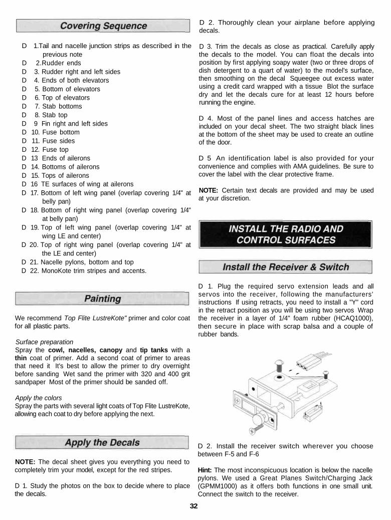
D 1. Plug the required servo extension leads and allservos into the receiver, following the manufacturers'instructions If using retracts, you need to install a "Y" cordin the retract position as you will be using two servos Wrapthe receiver in a layer of 1/4" foam rubber (HCAQ1000),then secure in place with scrap balsa and a couple ofrubber bands.
D 2. Install the receiver switch wherever you choosebetween F-5 and F-6
Hint: The most inconspicuous location is below the nacellepylons. We used a Great Planes Switch/Charging Jack(GPMM1000) as it offers both functions in one small unit.Connect the switch to the receiver.
32
D 3 Wrap the battery in 1/4" foam, then install it in theopening in the servo compartment. Connect the battery tothe switch.
D 4 Center all of the trim levers on your transmitter, thenturn on the transmitter and the receiver. Manually center allof the servo horns.
D 5. Use some scrap balsa to make a tray to support andsecure the receiver.
D 1. With reference to the above sketch, cut 18 hingesfrom the supplied 2" x 9" composite hinge material You willneed six hinges for the elevators and two for the rudder.Each aileron gets four hinges
D 2 Draw a centerline on the TE of the stab and the LE ofthe elevators. Do the same for the fin and rudder.
D 3 Use the plan as a guide to mark the locations of thehinges on all tail components - fin, rudder, stab, elevator,the wings' TE and the ailerons Refer to the Expert Tip thatfollows, then cut matching hinge slits in all parts Do notuse any glue until step 4.
INSTALLING CA HINGES
The hinge material supplied in this kit consists of a3-Iayer lamination of mylar and polyester It is speciallymade for the purpose of hinging model airplane controlsurfaces. Properly installed, this type of hinge providesthe best combination of strength, durability and ease ofinstallation We trust even our best show models to thesehinges, but it is essential to install them correctly.Please read the following instructions and follow themcarefully to obtain the best results These instructionsmay be used to effectively install any of the variousbrands of CA hinges.
The most common mistake made by modelers wheninstalling this type of hinge is not applying a sufficientamount of glue to fully secure the hinge over its entiresurface area, or, the hinge slots are very tight, restrictingthe flow of CA to the back of the hinges This results inhinges that are only "tack glued" approximately 1/8" to 1/4"into the hinge slots The following technique has beendeveloped to help ensure thorough and secure gluing.
A. Cut the hinge slot using a #11 blade in a standard #1knife handle The CA hinges provided have a thicknessthat fits this type of slot very well Trial fit the hinge intothe slot If the hinge does not slide in easily, work theknife blade back and forth in the slot a few times toprovide more clearance (it is really the back edge of theblade that does the work here in widening the slot)
B. Drill a 3/32" hole, 1/2" deep, in the center of thehinge slot. If you use a Dremel Moto-Tool® for this task, it
33
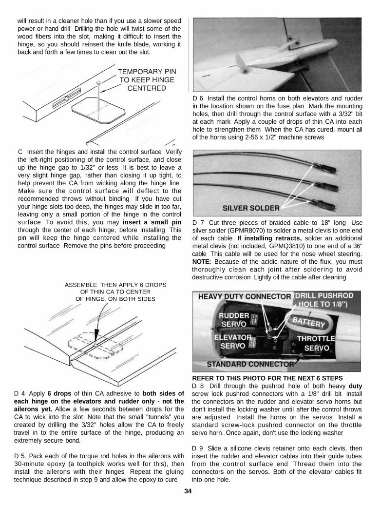
will result in a cleaner hole than if you use a slower speedpower or hand drill Drilling the hole will twist some of thewood fibers into the slot, making it difficult to insert thehinge, so you should reinsert the knife blade, working itback and forth a few times to clean out the slot.
D 6 Install the control horns on both elevators and rudderin the location shown on the fuse plan Mark the mountingholes, then drill through the control surface with a 3/32" bitat each mark Apply a couple of drops of thin CA into eachhole to strengthen them When the CA has cured, mount allof the horns using 2-56 x 1/2" machine screws
C Insert the hinges and install the control surface Verifythe left-right positioning of the control surface, and closeup the hinge gap to 1/32" or less It is best to leave avery slight hinge gap, rather than closing it up tight, tohelp prevent the CA from wicking along the hinge lineMake sure the control surface wil l deflect to therecommended throws without binding If you have cutyour hinge slots too deep, the hinges may slide in too far,leaving only a small portion of the hinge in the controlsurface To avoid this, you may insert a small pinthrough the center of each hinge, before installing Thispin will keep the hinge centered while installing thecontrol surface Remove the pins before proceeding
D 7 Cut three pieces of braided cable to 18" long Usesilver solder (GPMR8070) to solder a metal clevis to one endof each cable If installing retracts, solder an additionalmetal clevis (not included, GPMQ3810) to one end of a 36"cable This cable will be used for the nose wheel steering.NOTE: Because of the acidic nature of the flux, you mustthoroughly clean each joint after soldering to avoiddestructive corrosion Lightly oil the cable after cleaning
ASSEMBLE THEN APPLY 6 DROPSOF THIN CA TO CENTER
OF HINGE, ON BOTH SIDES
D 4 Apply 6 drops of thin CA adhesive to both sides ofeach hinge on the elevators and rudder only - not theailerons yet. Allow a few seconds between drops for theCA to wick into the slot Note that the small "tunnels" youcreated by drilling the 3/32" holes allow the CA to freelytravel in to the entire surface of the hinge, producing anextremely secure bond.
D 5. Pack each of the torque rod holes in the ailerons with30-minute epoxy (a toothpick works well for this), theninstall the ailerons with their hinges Repeat the gluingtechnique described in step 9 and allow the epoxy to cure
REFER TO THIS PHOTO FOR THE NEXT 6 STEPSD 8 Drill through the pushrod hole of both heavy dutyscrew lock pushrod connectors with a 1/8" drill bit Installthe connectors on the rudder and elevator servo horns butdon't install the locking washer until after the control throwsare adjusted Install the horns on the servos Install astandard screw-lock pushrod connector on the throttleservo horn. Once again, don't use the locking washer
D 9 Slide a silicone clevis retainer onto each clevis, theninsert the rudder and elevator cables into their guide tubesfrom the control surface end Thread them into theconnectors on the servos. Both of the elevator cables fitinto one hole.
34
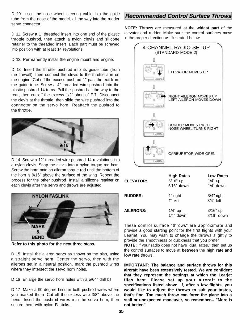
D 10 Insert the nose wheel steering cable into the guidetube from the nose of the model, all the way into the rudderservo connector.
D 11. Screw a 1" threaded insert into one end of the plasticthrottle pushrod, then attach a nylon clevis and siliconeretainer to the threaded insert Each part must be screwedinto position with at least 14 revolutions
D 12. Permanently install the engine mount and engine.
D 13 Insert the throttle pushrod into its guide tube (fromthe firewall), then connect the clevis to the throttle arm onthe engine Cut off the excess pushrod 1" past the exit fromthe guide tube Screw a 4" threaded wire pushrod into theplastic pushrod 14 turns Pull the pushrod all the way to therear, then cut off the excess 1/2" short of F-7 Disconnectthe clevis at the throttle, then slide the wire pushrod into theconnector on the servo horn Reattach the pushrod tothe throttle.
D 14 Screw a 12" threaded wire pushrod 14 revolutions intoa nylon clevis Snap the clevis into a nylon torque rod horn.Screw the horn onto an aileron torque rod until the bottom ofthe horn is 9/16" above the surface of the wing Repeat theprocess for the other pushrod Install a silicone retainer oneach clevis after the servo and throws are adjusted.
Refer to this photo for the next three steps.
D 15 Install the aileron servo as shown on the plan, usinga straight servo horn Center the servo, then with theailerons set in a neutral position, mark the pushrod wireswhere they intersect the servo horn holes.
D 16 Enlarge the servo horn holes with a 5/64" drill bit
D 17 Make a 90 degree bend in both pushrod wires whereyou marked them Cut off the excess wire 3/8" above thebend Insert the pushrod wires into the servo horn, thensecure them with nylon Faslinks.
NOTE: Throws are measured at the widest part of theelevator and rudder Make sure the control surfaces movein the proper direction as illustrated below
ELEVATOR MOVES UP
RIGHT AILERON MOVES UPLEFT AILERON MOVES DOWN
RUDDER MOVES RIGHTNOSE WHEEL TURNS RIGHT
CARBURETOR WIDE OPEN
High Rates Low Rates1/4" up1/4" down
3/4" right3/4" left
3/16" up3/16" down
5/16" up5/16" down
ELEVATOR:
1" rightRUDDER:1" left
1/4" up1/4" down
AILERONS:
These control surface "throws" are approximate andprovide a good starting point for the first flights with yourLearjet You may wish to change the throws slightly toprovide the smoothness or quickness that you preferNOTE: If your radio does not have 'dual rates," then set upthe control surfaces to move at between the high rate andlow rate throws.
IMPORTANT: The balance and surface throws for thisaircraft have been extensively tested. We are confidentthat they represent the settings at which the Learjetflies best. Please set up your aircraft to thespecifications listed above. If, after a few flights, youwould like to adjust the throws to suit your tastes,that's fine. Too much throw can force the plane into astall or unexpected maneuver, so remember... "More isnot better."
4-CHANNEL RADIO SETUP(STANDARD MODE 2)
35
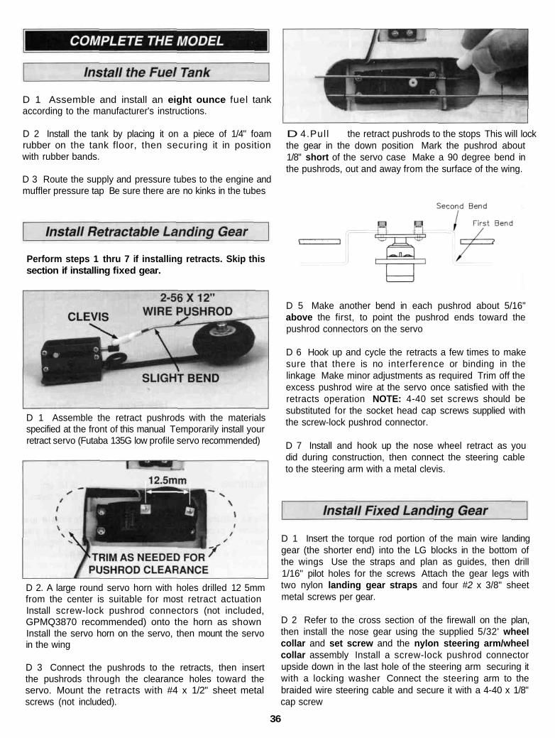
D 1 Assemble and install an eight ounce fuel tankaccording to the manufacturer's instructions.
D 2 Install the tank by placing it on a piece of 1/4" foamrubber on the tank floor, then securing it in positionwith rubber bands.
D 3 Route the supply and pressure tubes to the engine andmuffler pressure tap Be sure there are no kinks in the tubes
Perform steps 1 thru 7 if installing retracts. Skip thissection if installing fixed gear.
D 4.Pull the retract pushrods to the stops This will lockthe gear in the down position Mark the pushrod about1/8" short of the servo case Make a 90 degree bend inthe pushrods, out and away from the surface of the wing.
D 1 Assemble the retract pushrods with the materialsspecified at the front of this manual Temporarily install yourretract servo (Futaba 135G low profile servo recommended)
D 2. A large round servo horn with holes drilled 12 5mmfrom the center is suitable for most retract actuationInstall screw-lock pushrod connectors (not included,GPMQ3870 recommended) onto the horn as shownInstall the servo horn on the servo, then mount the servoin the wing
D 3 Connect the pushrods to the retracts, then insertthe pushrods through the clearance holes toward theservo. Mount the retracts with #4 x 1/2" sheet metalscrews (not included).
D 5 Make another bend in each pushrod about 5/16"above the first, to point the pushrod ends toward thepushrod connectors on the servo
D 6 Hook up and cycle the retracts a few times to makesure that there is no interference or binding in thelinkage Make minor adjustments as required Trim off theexcess pushrod wire at the servo once satisfied with theretracts operation NOTE: 4-40 set screws should besubstituted for the socket head cap screws supplied withthe screw-lock pushrod connector.
D 7 Install and hook up the nose wheel retract as youdid during construction, then connect the steering cableto the steering arm with a metal clevis.
D 1 Insert the torque rod portion of the main wire landinggear (the shorter end) into the LG blocks in the bottom ofthe wings Use the straps and plan as guides, then drill1/16" pilot holes for the screws Attach the gear legs withtwo nylon landing gear straps and four #2 x 3/8" sheetmetal screws per gear.
D 2 Refer to the cross section of the firewall on the plan,then install the nose gear using the supplied 5/32' wheelcollar and set screw and the nylon steering arm/wheelcollar assembly Install a screw-lock pushrod connectorupside down in the last hole of the steering arm securing itwith a locking washer Connect the steering arm to thebraided wire steering cable and secure it with a 4-40 x 1/8"cap screw
36
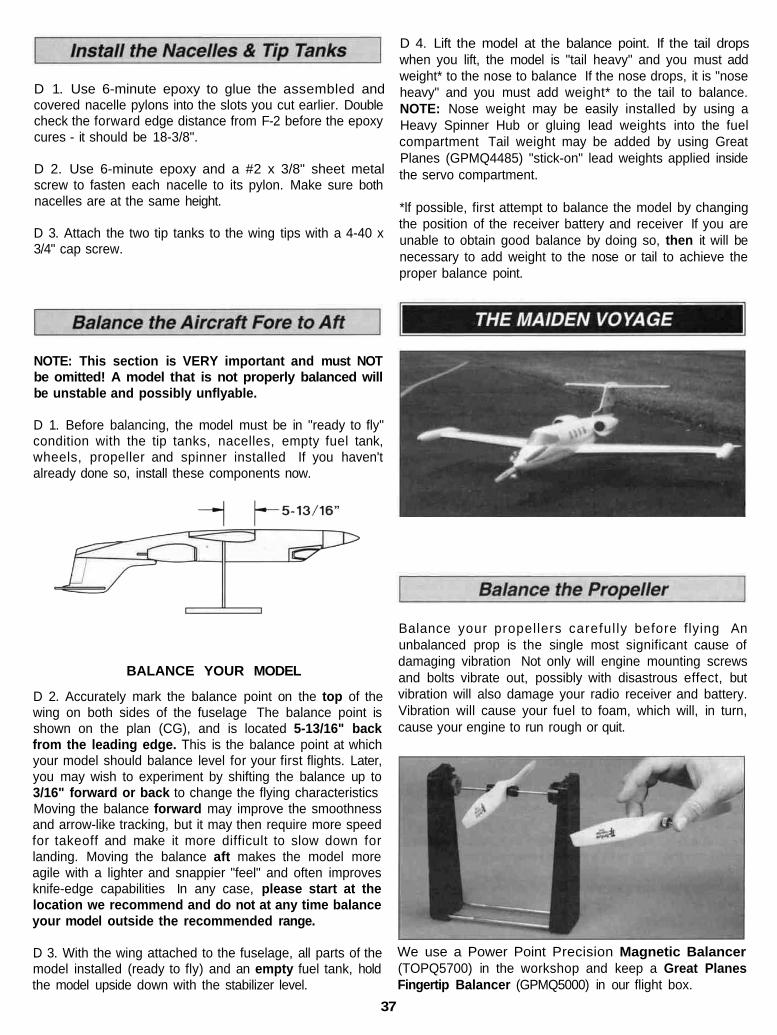
D 1. Use 6-minute epoxy to glue the assembled andcovered nacelle pylons into the slots you cut earlier. Doublecheck the forward edge distance from F-2 before the epoxycures - it should be 18-3/8".
D 2. Use 6-minute epoxy and a #2 x 3/8" sheet metalscrew to fasten each nacelle to its pylon. Make sure bothnacelles are at the same height.
D 3. Attach the two tip tanks to the wing tips with a 4-40 x3/4" cap screw.
D 4. Lift the model at the balance point. If the tail dropswhen you lift, the model is "tail heavy" and you must addweight* to the nose to balance If the nose drops, it is "noseheavy" and you must add weight* to the tail to balance.NOTE: Nose weight may be easily installed by using aHeavy Spinner Hub or gluing lead weights into the fuelcompartment Tail weight may be added by using GreatPlanes (GPMQ4485) "stick-on" lead weights applied insidethe servo compartment.
*lf possible, first attempt to balance the model by changingthe position of the receiver battery and receiver If you areunable to obtain good balance by doing so, then it will benecessary to add weight to the nose or tail to achieve theproper balance point.
NOTE: This section is VERY important and must NOTbe omitted! A model that is not properly balanced willbe unstable and possibly unflyable.
D 1. Before balancing, the model must be in "ready to fly"condition with the tip tanks, nacelles, empty fuel tank,wheels, propeller and spinner installed If you haven'talready done so, install these components now.
BALANCE YOUR MODEL
D 2. Accurately mark the balance point on the top of thewing on both sides of the fuselage The balance point isshown on the plan (CG), and is located 5-13/16" backfrom the leading edge. This is the balance point at whichyour model should balance level for your first flights. Later,you may wish to experiment by shifting the balance up to3/16" forward or back to change the flying characteristicsMoving the balance forward may improve the smoothnessand arrow-like tracking, but it may then require more speedfor takeoff and make it more difficult to slow down forlanding. Moving the balance aft makes the model moreagile with a lighter and snappier "feel" and often improvesknife-edge capabilities In any case, please start at thelocation we recommend and do not at any time balanceyour model outside the recommended range.
D 3. With the wing attached to the fuselage, all parts of themodel installed (ready to fly) and an empty fuel tank, holdthe model upside down with the stabilizer level.
Balance your propellers careful ly before flying Anunbalanced prop is the single most significant cause ofdamaging vibration Not only will engine mounting screwsand bolts vibrate out, possibly with disastrous effect, butvibration will also damage your radio receiver and battery.Vibration will cause your fuel to foam, which will, in turn,cause your engine to run rough or quit.
We use a Power Point Precision Magnetic Balancer(TOPQ5700) in the workshop and keep a Great PlanesFingertip Balancer (GPMQ5000) in our flight box.
37
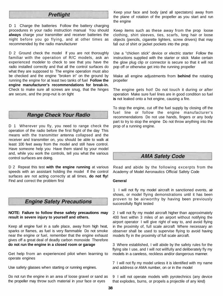
D 1 Charge the batteries Follow the battery chargingprocedures in your radio instruction manual You shouldalways charge your transmitter and receiver batteries thenight before you go f ly ing, and at other times asrecommended by the radio manufacturer
D 2 Ground check the model If you are not thoroughlyfamiliar with the operation of R/C models, ask anexperienced modeler to check to see that you have theradio installed correctly and that all the control surfaces dowhat they are supposed to The engine operation must alsobe checked and the engine "broken in" on the ground byrunning the engine for at least two tanks of fuel Follow theengine manufacturer's recommendations for break-in.Check to make sure all screws are snug, that the hingesare secure, and the prop-nut is on tight
D 1 Wherever you fly, you need to range check theoperation of the radio before the first flight of the day Thismeans with the transmitter antenna collapsed and thereceiver and transmitter on, you should be able to walk atleast 100 feet away from the model and still have control.Have someone help you Have them stand by your modeland, while you work the controls, tell you what the variouscontrol surfaces are doing.
D 2 Repeat this test with the engine running at variousspeeds with an assistant holding the model If the controlsurfaces are not acting correctly at all times, do not fly!Find and correct the problem first
NOTE: Failure to follow these safety precautions mayresult in severe injury to yourself and others.
Keep all engine fuel in a safe place, away from high heat,sparks or flames, as fuel is very flammable Do not smokenear the engine or fuel, remember that the engine exhaustgives off a great deal of deadly carbon monoxide Thereforedo not run the engine in a closed room or garage
Get help from an experienced pilot when learning tooperate engines
Use safety glasses when starting or running engines.
Do not run the engine in an area of loose gravel or sand asthe propeller may throw such material in your face or eyes
Keep your face and body (and all spectators) away fromthe plane of rotation of the propeller as you start and runthe engine
Keep items such as these away from the prop looseclothing, shirt sleeves, ties, scarfs, long hair or looseobjects (pencils, cigarette lighters, screw drivers) that mayfall out of shirt or jacket pockets into the prop.
Use a "chicken stick" device or electric starter Follow theinstructions supplied with the starter or stick Make certainthe glow plug clip or connector is secure so that it will notpop off or otherwise get into the running propeller
Make all engine adjustments from behind the rotatingpropeller
The engine gets hot! Do not touch it during or afteroperation Make sure fuel lines are in good condition so fuelis not leaked onto a hot engine, causing a fire.
To stop the engine, cut off the fuel supply by closing off thefuel line or follow the engine manufacturer 'srecommendations Do not use hands, fingers or any bodypart to try to stop the engine Do not throw anything into theprop of a running engine.
Read and abide by the fol lowing excerpts from theAcademy of Model Aeronautics Official Safety Code
General
1 I will not fly my model aircraft in sanctioned events, airshows, or model flying demonstrations until it has beenproven to be airworthy by having been previouslysuccessfully flight tested
2 I will not fly my model aircraft higher than approximately400 feet within 3 miles of an airport without notifying theairport operator I will give right of way to, and avoid flyingin the proximity of, full scale aircraft Where necessary anobserver shall be used to supervise flying to avoid havingmodels fly in the proximity of full scale aircraft.
3 Where established, I will abide by the safety rules for theflying site I use, and I will not willfully and deliberately fly mymodels in a careless, reckless and/or dangerous manner.
7 I will not fly my model unless it is identified with my nameand address or AMA number, on or in the model
9 I will not operate models with pyrotechnics (any devicethat explodes, burns, or propels a projectile of any kind)
38
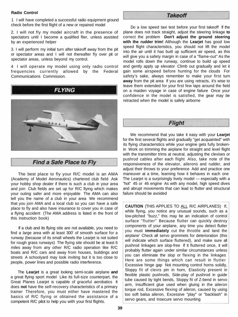
Radio Control
1 I will have completed a successful radio equipment groundcheck before the first flight of a new or repaired model
2. I will not fly my model aircraft in the presence ofspectators until I become a qualified flier, unless assistedby an experienced helper
3. I will perform my initial turn after takeoff away from the pitor spectator areas and I will not thereafter fly over pit orspectator areas, unless beyond my control.
4 I will operate my model using only radio controlfrequencies current ly allowed by the FederalCommunications Commission.
The best place to fly your R/C model is an AMA(Academy of Model Aeronautics) chartered club field Askyour hobby shop dealer if there is such a club in your areaand join Club fields are set up for R/C flying which makesyour outing safer and more enjoyable The AMA can alsotell you the name of a club in your area We recommendthat you join AMA and a local club so you can have a safeplace to fly and also have insurance to cover you in case ofa flying accident (The AMA address is listed in the front ofthis instruction book)
If a club and its flying site are not available, you need tofind a large area with at least 300' of smooth surface for arunway (because of its small wheels the Learjet is not suitedfor rough grass runways) The flying site should be at least 6miles away from any other R/C radio operation like R/Cboats and R/C cars and away from houses, buildings andstreets A schoolyard may look inviting but it is too close topeople, power lines and possible radio interference.
The Learjet is a great looking semi-scale airplane anda great flying sport model Like its full-size counterpart, theGreat Planes Learjet is capable of graceful aerobatics Itdoes not have the self-recovery characteristics of a primarytrainer Therefore, you must either have mastered thebasics of R/C flying or obtained the assistance of acompetent R/C pilot to help you with your first flights.
Do a low speed taxi test before your first takeoff If theplane does not track straight, adjust the steering linkage tocorrect the problem Don't adjust the ground steeringwith the rudder trim! Although the Learjet has good lowspeed flight characteristics, you should not lift the modelinto the air until it has built up sufficient air speed, as thiswill give you a safety margin in case of a "flame-out" As themodel rolls down the runway, continue to build up speedand gently apply up elevator Climb out gradually and let itgain some airspeed before hunting for the clouds Forsafety's sake, always remember to make your first turnaway from the pit area If you are using retracts, it's wise toleave them extended for your first few laps around the fieldon a maiden voyage in case of engine failure Once yourconfidence in the model is satisfied, the gear may beretracted when the model is safely airborne
We recommend that you take it easy with your Learjetfor the first several flights and gradually "get acquainted" withits flying characteristics while your engine gets fully broken-in Work on trimming the airplane for straight and level flightwith the transmitter trims at neutral, adjusting the clevises orpushrod cables after each flight Also, take note of theresponsiveness of the elevator, ailerons and rudder, andadjust their throws to your preference Add and practice onemaneuver at a time, learning how it behaves in each oneThe Learjet is a surprisingly lively model — especially with a"hot" 45 or 46 engine As with any model, high speed divesand abrupt movements that can lead to flutter and structuralfailure should be avoided
CAUTION (THIS APPLIES TO ALL R/C AIRPLANES) If,while flying, you notice any unusual sounds, such as alow-pitched "buzz," this may be an indication of controlsurface "f lutter" Because flutter can quickly destroycomponents of your airplane, any time you detect flutteryou must immediately cut the throttle and land theairplane' Check all servo grommets for deterioration (thiswill indicate which surface fluttered), and make sure allpushrod linkages are slop-free If it fluttered once, it willprobably flutter again under similar circumstances unlessyou can eliminate the slop or flexing in the linkagesHere are some things which can result in f lut terExcessive hinge gap Not mounting control horns solidly,Sloppy fit of clevis pin in horn, Elasticity present inflexible plastic pushrods, Side-play of pushrod in guidetube caused by tight bends, Sloppy fit of Z-bend in servoarm, Insufficient glue used when gluing in the ailerontorque rod, Excessive flexing of aileron, caused by usingtoo soft balsa aileron, Excessive "play" or "backlash" inservo gears, and Insecure servo mounting
39
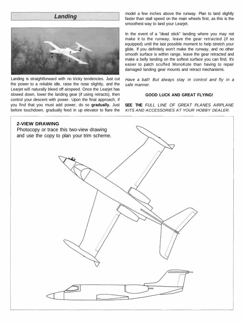
Landing is straightforward with no tricky tendencies. Just cutthe power to a reliable idle, raise the nose slightly, and theLearjet will naturally bleed off airspeed. Once the Learjet hasslowed down, lower the landing gear (if using retracts), thencontrol your descent with power. Upon the final approach, ifyou find that you must add power, do so gradually. Justbefore touchdown, gradually feed in up elevator to flare the
model a few inches above the runway. Plan to land slightlyfaster than stall speed on the main wheels first, as this is thesmoothest way to land your Learjet.
In the event of a "dead stick" landing where you may notmake it to the runway, leave the gear retracted (if soequipped) until the last possible moment to help stretch yourglide. If you definitely won't make the runway, and no othersmooth surface is within range, leave the gear retracted andmake a belly landing on the softest surface you can find. It'seasier to patch scuffed MonoKote than having to repairdamaged landing gear mounts and retract mechanisms.
Have a ball! But always stay in control and fly in asafe manner.
GOOD LUCK AND GREAT FLYING!
SEE THE FULL LINE OF GREAT PLANES AIRPLANEKITS AND ACCESSORIES AT YOUR HOBBY DEALER.
2-VIEW DRAWINGPhotocopy or trace this two-view drawingand use the copy to plan your trim scheme.