instruction manual - mettler toledo balances & scales …€¦ · · 2018-03-08• one - 5...
TRANSCRIPT

Part No. 58130082
5000TOCe Sensor
Instruction Manual

©Mettler-Toledo Thornton, Inc. 2009
No part of this manual may be reproduced or transmitted in any form or by any means, electronic or mechanical, including photocopying (other than where specifically noted), for any purpose without the express written permission of Mettler-Toledo Inc.
U.S. Government Restricted Rights: This documentation is furnished with Restricted Rights.
METTLER TOLEDO THORNTON RESERVES THE RIGHT TO MAKE REFINEMENTS OR CHANGES WITHOUT NOTICE.
This document contains proprietary information, which is protected by copyright. All rights are reserved. No part of this document may be photocopied (other than where specifically noted), reproduced or translated, into another language without the prior written consent of Mettler-Toledo Thornton, Inc.

IMPORTANT SAFETY INFORMATION
- Please read thoroughly before operating the 5000TOCe Sensor product - • Follow all warnings, cautions, and instructions indicated on and supplied with this product. • Install equipment as specified in this instruction manual. Follow appropriate local and national codes. • Use only factory documented components for repair. Tampering or unauthorized substitution of parts and
procedures can affect the performance and cause unsafe operation of your process as well as void factory warranties.
• Protective covers must be in place unless qualified personnel are performing maintenance. • If this equipment is used in a manner not specified by the manufacturer, the protection provided by the
equipment against hazards may be impaired. • Prior to shipping sensor back to the factory for repair or re-calibration, water MUST be drained from sensor to
avoid damage due to freezing.
WARNINGS: • Installation of cable connections and servicing of this product require access to shock hazard voltage levels. • Main power must employ a switch or circuit breaker as the disconnecting device for the equipment. • Electrical installation must be in accordance with the National Electrical Code and/or any other applicable
national or local codes. • Safety and performance require that this instrument be connected and properly grounded through a three-
wire power source. • PROCESS UPSETS: Because process and safety conditions may depend on consistent operation of this
instrument, provide appropriate means to maintain operation during sensor cleaning, replacement, or sensor or instrument calibration.
• Ozone gas (O3) is generated inside the 5000TOCe Sensor enclosure during normal operation. The smell of ozone may be apparent when opening the front cover of the enclosure and caution should be taken when opening. Prolonged exposure to ozone gas is hazardous and may cause health problems.
This manual includes safety information with the following designations and formats: WARNING: POTENTIAL FOR PERSONAL INJURY. CAUTION: possible instrument damage or malfunction. NOTE: important operating information.
WARNING: UV RADIATION HAZARD Apply power to UV lamp only when installed in housing in accordance with instruction manual.
DO NOT remove UV lamp from housing unless power is off. Always protect eyes and skin from exposure to UV light

Definition of Equipment Symbols
On the instrument indicates: Warning, risk of electric shock.
On the instrument indicates: Caution (refer to accompanying documents).
~ On the instrument indicates: There is alternating current present.

TABLE OF CONTENTS
1. INTRODUCTION .................................................................................................................. 1 2. INSTALLATION.................................................................................................................... 1
UNPACKING ........................................................................................................................ 1 3. INSTRUMENT DESCRIPTION............................................................................................. 2
INSTRUMENT INSTALLATION............................................................................................ 2 SAMPLE TUBING CONNECTIONS ..................................................................................... 2 SAMPLE CONDITIONING COIL P/N 58 079 511................................................................. 4 AC POWER CONNECTION ................................................................................................. 4 SMART SENSOR CONNECTION ........................................................................................ 5 SENSOR DETAILS............................................................................................................... 5 HIGH PRESSURE APPLICATIONS ..................................................................................... 6 POTENTIAL CONDENSATION APPLICATIONS ................................................................. 6 HIGH TEMPERATURE APPLICATIONS.............................................................................. 6
4. TOC FUNCTIONS ................................................................................................................ 6 770MAX TOC MENUS.......................................................................................................... 7 SET FLOW RATE................................................................................................................. 8 UV LAMP .............................................................................................................................. 8 LAMP REMAIN/LAMP RESET/LAMP LIMIT......................................................................... 8 AUTO START ....................................................................................................................... 8 RINSE TIME ......................................................................................................................... 8 AUTOBALANCE/AUTOBALANCE TIME/ AUTOBALANCE LIMIT ....................................... 8 SENSOR KEY LOCK............................................................................................................ 9 CONDUCTIVITY LIMIT......................................................................................................... 9 OVER-RIDE LIMIT................................................................................................................9
5. OPERATION ........................................................................................................................ 9 INITIAL START-UP...............................................................................................................9 SETTING SAMPLE FLOW RATE....................................................................................... 10 START TOC MEASUREMENT........................................................................................... 10 NORMAL OPERATION ...................................................................................................... 11
6. SYSTEM SUITABILITY TESTING...................................................................................... 11 7. CALIBRATION ................................................................................................................... 11
770MAX SOFTWARE REVISION 5.2 CALIBRATION “TYPE” OPTIONS. ......................... 12 CALIBRATION MENU: ....................................................................................................... 13 MEASUREMENT MENU: ................................................................................................... 13
8. SERVICE AND MAINTENANCE........................................................................................ 13 UV LAMP REPLACEMENT ................................................................................................ 14 HIGH CAPACITY INLET FILTER REPLACEMENT............................................................ 15 INTERNAL TUBING REPLACEMENT................................................................................ 15 FRONT PANEL CLEANING ............................................................................................... 15 TROUBLESHOOTING CHECKLIST................................................................................... 16 ERRORS & FAULTS .......................................................................................................... 16
9. SPECIFICATIONS.............................................................................................................. 18 TOC PERFORMANCE SPECIFICATIONS......................................................................... 18
10. ACCESSORIES AND CONSUMABLE ITEMS................................................................... 19

5000TOCE SENSOR ACCESSORIES............................................................................... 19 5000TOCE SENSOR CONSUMABLE ITEMS.................................................................... 19
11. RATINGS ........................................................................................................................... 20 CE DECLARATION ............................................................................................................ 20 UL LISTING........................................................................................................................ 20
12. WARRANTY....................................................................................................................... 21

1
1. INTRODUCTION The 5000TOCe Sensor is an addition to the Smart family of sensors available for use with the 770MAX Multiparameter Analyzer/Transmitter. This manual covers the routine operation of the 5000TOCe sensor and also includes instructions for using the functions in the 770MAX instrument that are specific to the 5000TOCe Sensor. The 5000TOCe Sensor and 770MAX instrument provide continuous, accurate and repeatable total organic carbon measurement of pure and ultrapure water. Operation of this equipment should be in accordance with its intended use only and should adhere to the installation and operational guidelines described in this manual. Please refer to the 770MAX Multiparameter Analyzer/Transmitter Manual, Part No. 84372, for detailed instructions of instrument functions beyond those specific to the 5000TOCe sensor. NOTE: Ensure that the 770MAX analyzer used with the 5000TOCe Sensor is software version 5.1 or above. You may upgrade a 770MAX instrument to operate with the 5000TOCe Sensor if the instrument is currently operating on software version 3.0 or higher. Contact Mettler-Toledo Thornton, Inc. Technical Service for details. The 5000TOCe Sensor has more functions than most 770MAX Smart sensors, providing more extensive interface between instrument and sensor. A maximum of two 5000TOCe Sensors can be installed on one 770MAX instrument, in any of the four smart input channels. A single 770MAX patch cable is used to interface each sensor with the instrument. The remaining channels may be used for other Smart Sensors.
2. INSTALLATION UNPACKING Carefully unpack the 5000TOCe sensor. The box should contain the following items: • 5000TOCe Sensor • 5000TOCe Sensor Instruction Manual • 5000TOCe Start-up Sheet • Certificate of Calibration • Installation Kit includes: • One - 6 foot (2m) length of PTFE tubing, 0.125 inch (3mm) O.D. • One - 5 foot (1.5m) length of tubing, 0.31 inch (8mm) O.D. • One stainless steel drain tube • One - Plastic 30cc Syringe • One - Tool, 5000TOCe Cover • One - High Capacity Inlet Filter Assembly • One - Adapter, 0.25 inch (6mm) O.D. to 0.125 inch (3mm) O.D. Tubing Reducer • One – Sample Conditioning Coil
2
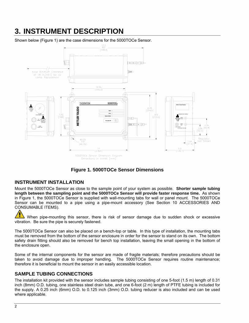
3. INSTRUMENT DESCRIPTION Shown below (Figure 1) are the case dimensions for the 5000TOCe Sensor.
RM
TTELE
OLOT
DE
Sensor Status
UV Lamp ON
Error
Fault
770MAXCONNECTION
DO NOTOPEN WHEN
UV LAMP IS ON
UV LAMPREPLACEMENT COVER
SAMPLEINLET
SAMPLEOUTLET
Mettler-Toledo ThorntonTHORNTON
DRAIN BEFORE SHIPPING
ACPOWER
HIGH VOLTAGEDISCONNECTPOWER FORSERVICING
85 PSIG MAX PRESSURE
DO NOTOPEN WHEN
UV LAMP IS ON
DO NOTOPEN WHEN
UV LAMP IS ON
FLOW CONTROL
5000TOCe
Figure 1. 5000TOCe Sensor Dimensions INSTRUMENT INSTALLATION Mount the 5000TOCe Sensor as close to the sample point of your system as possible. Shorter sample tubing length between the sampling point and the 5000TOCe Sensor will provide faster response time. As shown in Figure 1, the 5000TOCe Sensor is supplied with wall-mounting tabs for wall or panel mount. The 5000TOCe Sensor can be mounted to a pipe using a pipe-mount accessory (See Section 10 ACCESSORIES AND CONSUMABLE ITEMS).
When pipe-mounting this sensor, there is risk of sensor damage due to sudden shock or excessive vibration. Be sure the pipe is securely fastened. The 5000TOCe Sensor can also be placed on a bench-top or table. In this type of installation, the mounting tabs must be removed from the bottom of the sensor enclosure in order for the sensor to stand on its own. The bottom safety drain fitting should also be removed for bench top installation, leaving the small opening in the bottom of the enclosure open. Some of the internal components for the sensor are made of fragile materials; therefore precautions should be taken to avoid damage due to improper handling. The 5000TOCe Sensor requires routine maintenance; therefore it is beneficial to mount the sensor in an easily accessible location. SAMPLE TUBING CONNECTIONS The installation kit provided with the sensor includes sample tubing consisting of one 5-foot (1.5 m) length of 0.31 inch (8mm) O.D. tubing, one stainless steel drain tube, and one 6-foot (2 m) length of PTFE tubing is included for the supply. A 0.25 inch (6mm) O.D. to 0.125 inch (3mm) O.D. tubing reducer is also included and can be used where applicable.

3
The following items are necessary to ensure the proper installation of the sensor: • Sample isolation valve (not provided with sensor). • 0.125 inch compression tube fitting for sample point (common tube fitting adapters are available from
Thornton; see Section 10, ACCESSORIES AND CONSUMABLE ITEMS). NOTE: The sample point should contain a shut-off valve to isolate the sensor when necessary. Proper installation guidelines should be followed when installing this valve to reduce the possibility of air entrapment or sediment in the sample line.
RM
TTELE
THORNTON
OLOT
DE
Sensor Status
UV Lamp ON
Error
Fault
5000TOCe
Figure 2. Sample 5000TOCe Sensor Installation • Remove the protective covers from the sample connections on the sensor. • Attached the open tube end of the PTFE tubing to the sample isolation valve. Cut excess tubing to minimize
sample tubing length. Be sure all fittings are properly fastened to avoid leaks and the possibility of air ingress. Flush the sample inlet tubing to remove any particles that may be in the line or fittings before connecting it to the 5000TOCe Sensor, or prior to initial sensor startup. • Connect the stainless steel drain tube to the Sample Outlet connection. The fitting is attached to the tube;
therefore thread the fitting into the Sample Outlet connection on the sensor. Do not over tighten. • Locate the High Capacity Inlet Filter Assembly provided in the sensor installation kit. The male-threaded end
of the assembly is screwed into the female-threaded sample inlet fitting. Secure the assembly with a wrench to ensure the connection is tight. Do not over tighten.
• Connect the 0.125 inch (3mm) PTFE tubing to the high capacity inlet filter by securing the tubing in the compression fitting on the assembly. Do not over tighten.
• Run the safety drain tubing to an atmospheric drain located close to the sensor. See Figure 2, for dimensional detail of the drain location. Take note of the 6” (15cm) to 36” (90cm) drain requirement.
Important! The stainless steel drain tube must be fed to a nearby standpipe or drain sump to create an air gap and prevent siphoning. Installation must adhere to the dimensions shown in Figure 2 for proper sensor operation. • Once all tubing connections are complete and the sample inlet tubing has been flushed to drain, sample water
can be introduced to the sensor. The inlet needle valve is used to vary flowrate and may need adjustment to establish flow. Refer to Figure 5. First, turn the adjustment knob fully clockwise to a closed position. Then,

4
turn adjustment knob counter-clockwise three turns. Slowly open the sample point isolation valve until flow is observed at the sample outlet drain. Once there is flow, check to be sure there are no leaks inside the enclosure. Allow the sensor to initially flush with sample water (4-24 hrs is recommended). For more details on inlet needle valve operation, see Section 5. Shut off the sample flow to the sensor and connect AC power to the 5000TOCe Sensor.
SAMPLE CONDITIONING COIL P/N 58 079 511
Note: Use of the Sample Conditioning Coil requires a minimum sample pressure of 1.7 bar (25 psig) at the inlet of the coil to ensure sufficient flow through the 5000TOCe sensor. If the pressure is insufficient to meet minimum requirements, a pump will be required.
Detail A 1) Remove compression fitting from filter assembly. As shown, insert port connector into compression fitting that was removed
from filter. Reconnect compression fitting to the filter assembly and tighten to crimp. Do not over tighten. 2) Connect Fitting A (1/8”-1/16”) of Sample Conditioning Coil to the port connector and tighten to crimp. Do not over tighten. 3) Attach Fitting B (1/16” X 1/4” NPT) of Sample Conditioning Coil to an appropriate connection on the process pipe. 4) Ensure that excessive force is not applied to the inlet fittings. If necessary, support the Sample Conditioning Coil in an
appropriate manner. Note: The Sample Conditioning Coil can be extended in length to 10’ (3m) maximum. AC POWER CONNECTION As shown in the left side view of Figure 1, there is a bulkhead cable gland located on the left-hand side of the sensor enclosure labeled ‘AC POWER’ to allow for the passage of the AC power cable (not provided with sensor). If the installation requires hard conduit installation for AC power, this fitting may be removed and the hole can be used to terminate a conduit fitting. NOTE: For conduit installation, use a watertight fitting and hub that comply with the requirements of UL514B. Connect the conduit hub to the conduit before attaching the fitting to the analyzer (UL508-263.16). The opening accepts a 3/8” (9mm) NPT conduit fitting with nut. The terminal connections for AC power are located on the printed circuit board mounted to the front cover of the sensor, as shown in Figure 3. Keep AC power separated from all other internal wiring. Use the fasteners provided to secure the power wires. Be sure there is enough excess to avoid putting mechanical stress on the wiring when the front door is fully opened. The diagram below shows the terminal connections for AC power. Be sure the line fuse is properly installed when making electrical connections. A spare fuse kit is available from Thornton. See Section 10 for ordering information.

5
EARTH GROUNDNEUTRALLINE
AC LINE IN
LINE FUSE
Figure 3. Power Connection SMART SENSOR CONNECTION Also located on the left-hand side of the sensor enclosure (refer to Figure 1) is the 770MAX Smart Sensor connector, labeled ‘770MAX Connection’. The standard 770MAX patch cable attaches directly to this connector. Align the keys of the two connectors and twist the locking nut to secure the patch cable. Once both electrical connections are secured, the sample shut-off valve can be opened and the sensor flushed with sample water. Section 3 of this manual defines the TOC functions available when using the 5000TOCe Sensor in conjunction with the 770MAX instrument. Read carefully prior to operating the 5000TOCe Sensor. SENSOR DETAILS The 5000TOCe Sensor is designed with four local LED indicators and a UV Lamp control key on the front panel, as shown in Figure 4. The LEDs are designed to provide local indication of sensor status. The operation of the LEDs is synchronized with the 770MAX display status messages that appear in the 6-digit measurement name location.
LED Indicators: FUNCTION COLOR OPERATION FAULT RED Flashes during Fault condition, sensor operation stopped
ERROR AMBER (Orange) Illuminates during Error condition, sensor remains operational
SENSOR STATUS GREEN Illuminates whenever AC Power is on and 770MAX patch
cable is connected to the sensor UV LAMP ON GREEN Illuminates whenever the UV Lamp is on
The UV Lamp control key is designed to provide a local On/Off control for the UV lamp to allow for quick lamp change-out and assist the operator during troubleshooting, if necessary. NOTE: If the UV Lamp Key is pressed to turn the UV Lamp off, the UV Lamp cannot be turned on from the 770MAX, it can only be turned on by pressing the sensor key again.

6
RM
TTELE
THORNTON
OLOT
DE
Sensor Status
UV Lamp ON
Error
Fault
5000TOCe
Figure 4. 5000TOCe Sensor Front Panel The front cover of the sensor is hinged on the left side. Located at the top and bottom right corners of the sensor enclosure are two triangle-shaped door fasteners. The installation kit provided with the Sensor includes the special tool needed to loosen these fasteners and open the front door to the enclosure. Periodic access will be required to perform routine service and maintenance. Additional front cover tools are available from Thornton. See Section 10 for part numbers and descriptions. HIGH PRESSURE APPLICATIONS For installations with process pressure above 85 psig (5.9 bar), the High Pressure Regulator (p/n 58 091 552) is required (see Figure 2). Installation instructions are supplied with the High Pressure Regulator. POTENTIAL CONDENSATION APPLICATIONS Certain ambient and process temperatures may cause condensation to occur inside the 5000TOCe Sensor. The Mettler-Toledo Thornton Sample Conditioning Coil (p/n 58 091 511) is designed to eliminate condensation conditions. HIGH TEMPERATURE APPLICATIONS For water temperatures above 70°C (158°F), the Sample Conditioning Coil (p/n 58 091 511) is required. In high pressure applications, the High Pressure Regulator (p/n 58 091 552) must be installed downstream of the Sample Conditioning Coil.
4. TOC Functions The 5000TOCe Sensor is part of the 770MAX family of Smart sensors. The 770MAX will automatically identify the 5000TOCe Sensor when it is connected to the 770MAX and all cell constants and factory calibration data are automatically read and stored. The 770MAX will also provide TOC specific menus for the channel connected to the 5000TOCe Sensor. The 5000TOCe Sensor is configured with factory default settings to minimize measurement setup time. These default settings allow for sensor operation with minimal keystrokes. The 5000TOCe Sensor has more features than other Smart sensors and may require a higher level of operational setup. Once these parameters are set, the TOC sensor will function automatically, similar to other Smart sensors, and will require user interface only for periodic service and maintenance. Measurements available from the 5000TOCe Sensor include TOC, Conductivity/Resistivity (compensated and uncompensated) and Temperature. Refer to the 770MAX manual for instructions on configuring the display and the use of these measurements for other control functions available with the 770MAX instrument.

7
770MAX TOC MENUS The menu tree shown on the next page appears in the Measurements menu of the 770MAX when the 5000TOCe Sensor is connected to one of the four 770MAX Smart channels. The information shown inside the menu blocks reflects the factory default values when a new sensor is connected to the 770MAX. To the right of the menu blocks is the definition of each menu item and the user options available. Menu items shown in bold are user configurable. It is important to be familiar with the TOC menus prior to operating the 5000TOCe sensor. NOTE: All of the setup parameters described in this section are located within the MEASUREMENTS menu of the 770MAX. Once in the ‘Measurements’ screen, press page-down three times to arrive at the TOC Setup prompt screen. The menu will prompt you to ‘Push 5’ to enter the specific TOC Setup menus. The factory default values are as shown. Press Enter to move the cursor from one field to another. Press the up or down arrow to change the “Yes/No” or enter numbers using the keypad. 770MAX TOC MENUS Software revision 5.2. Main Menu Select a menu using ↑↓ then press Enter Goto: Measurements
MEASUREMENT: A ↑ Sensor Input: Chan 1 Units: gC/L Auto Name:none ↓
TOC Setup Ch 1 ↑Lamp Remain: 4500 hr Lamp Reset: 01/01/07 Lamp Limit: 4500 hr ↓
Sensor Input: Shows channel connected to measurement Units: Options are TOC (ppt, ppb, ppm, Auto), gC/L (n, µ, m, Auto) Name: 6-digit user entered name
Lamp Remain: Time remaining on UV Lamp limit. Lamp Reset: User entered date of last UV Lamp change. Lamp Limit: User selectable from 400 to 9999 hours. 4500 hours recommended.
MEASUREMENT: A ↑ Multiplier1L: 1.23456 Adder1L: 0.56789 Averaging: Special ↓
TOC Setup Ch 1 ↑Auto Start: No Rinse Time: 015 min Flow: 20.00 ml/min ↓
*Multiplier: TOC calibration constant *Adder: TOC calibration constant Averaging: Options are None, Low, Medium, High, and Special *Note: There are two Multipliers and Adders for multi-linear calibration (available on 770MAX software rev 5.2)
Auto Start: No/Yes. Allows sensor to automatically start a measurement when power is restored to a 5000TOCe Sensor. Rinse Time: Selectable from 1 to 999 minutes. Flow: Flow rate can be viewed as a displayed number (available on 770MAX software rev 5.2).
MEASUREMENT: A ↑ Set Flow Rate: No UV Lamp: Off Push 5 for TOC menu ↓
TOC Setup Ch 1 ↑AutoBal: No AutoBal Time: 4500 hr AutoBal Limit: 15% ↓
Set Flow Rate: Yes/No. Allows the user to adjust the flow rate through the sensor when Yes is selected. Must be turned back to No once complete. UV Lamp: On/Off. Turns the UV lamp on or off. (For initial start-up, the sensor key must be pushed)
AutoBal: Yes/No. Option for balancing both conductivity sensors before starting a TOC measurement. Factory default is No. AutoBal time: Selectable from 24 to 4500 hours. AutoBal limit: Selectable from 0 to 20%.
MEASUREMENT: A ↑ Resolution: Auto ↓
Resolution: Measurement display resolution (Auto, 1., 0.1, 0.01, 0.001)
TOC Setup Ch 1 ↑AutoBal in N/A hr AutoBal Hold: Yes AutoBal Now: N/A ↓
AutoBal in: If required, set time before next Autobalance. AutoBal Hold: Yes/No. Option to hold the last measurement during an Auto-balance. AutoBal Now: Yes/No. Allows an auto-balance immediately upon selecting “yes” and exiting menu.
MEASUREMENT: A ↑ Reading = 1.2345 gC/L 5803600X SN=00342391 Cal Date: 01/01/07
Reading: Shows Current TOC measurement TOC Sensor Part # and Serial # Cal Date: Date of last calibration
TOC Setup Ch 1 ↑Sensor Key Lock: No Cond Limit: 2.0000 µS Over-ride limit: No
Sensor Key Lock: Yes/No. Allows the user to disable the key on the 5000TOCe Sensor. Cond. Limit: Selectable. Set above 0.0. Over-ride limit: Yes/No. If No is selected, error message will occur when conductivity limit is exceeded. Conductivity limit will be ignored when Yes is selected.
Bold text in menus indicates user selectable field.

8
SET FLOW RATE The capability to set the flow rate is located in the main TOC screen. When Set Flow Rate is set to ‘Yes’, the sensor LED lights act as flow indicators during the flow adjustment process. See Section 4, for details on how and when to perform a flow adjustment. Once the flow is adjusted to the proper level, the user must change the Set Flow Rate: ‘Yes’ back to ‘No’ to confirm the flow rate is properly set. UV LAMP This function allows you to turn on or off the UV lamp. For initial start-up, the sensor key “UV Lamp On” must be pressed. LAMP REMAIN/LAMP RESET/LAMP LIMIT The UV lamp in the 5000TOCe Sensor is rated for 4500 hours of normal usage. The 770MAX will display an error message when the lamp operating time has exceeded the lamp limit. The user can reset the Lamp Limit from 400 to 9999 hours. It is the user’s responsibility to assure by calibration or other means that the lamp is outputting sufficient UV light for the sensor to make accurate TOC measurements. To set the Lamp Limit or the Lamp Reset date, enter the Measurement menu for the measurement displaying the TOC value. Press Page Down until “Push 5 for TOC menu” is displayed. Push 5 and then Page Down until the lamp parameters are displayed. The Lamp Remain value is the number of hours remaining before the Lamp Limit has been exceeded. This value cannot be directly changed. When a new lamp is installed, the date should be entered using the keypad into the Lamp Reset value. Press Enter after the new date is entered. The Lamp Remain time will be reset to the Lamp Limit value. The Lamp Limit is changed by directly entering a value for 400 to 9999 hours. When the lamp operating time is exceeded, an Error message will be displayed. AUTO START Auto Start is a feature that allows the 5000TOCe Sensor to automatically start making TOC measurements when it is connected to a 770MAX or when the 770MAX restarts after a power failure. The factory default setting for the Auto Start function is ‘No’. Therefore during initial start-up, the 770MAX will identify the sensor as a 5000TOCe Sensor, yet will not start a TOC measurement. To start a TOC measurement, the user must go to the ‘UV Lamp: On/Off’ screen and set this mode to ‘On’ to turn on the UV lamp and start a TOC measurement. The user may also push the UV lamp button at the Sensor to start a measurement. Once the ‘Auto Start’ mode is set to ‘Yes’, it is no longer necessary to turn the ‘UV Lamp’ option to ‘On’ as the ‘Auto Start’ function will override the UV Lamp: On/Off function. To enable Auto Start, enter the measurement menu for the measurement displaying the TOC value. Press Page Down until “Push 5 for TOC menu” is displayed. Push 5 and then press Page Down until the Auto Start function is displayed. Select ‘Yes’ if you want to enable the Auto Start feature. Select ‘No’ to disable this feature. In the event that direct human interaction is desired to re-start measurements, this feature should be set to ‘No’. RINSE TIME The Rinse Time is the time at start up (initial connection to a 770MAX, 770MAX system reset or 770MAX power reset) that the sensor will have sample water flowing through it before making TOC measurements. The Rinse Time can be set from 1 to 999 minutes. To set the Rinse Time, enter the measurement menu for the measurement displaying the TOC value. Press Page Down until “Push 5 for TOC menu” is displayed. Push 5 and then press Page Down until the Rinse Time is displayed. Using the 770MAX keypad, enter the Rinse Time desired and press Enter. AUTOBALANCE/AUTOBALANCE TIME/ AUTOBALANCE LIMIT The 5000TOCe Sensor is capable of automatically balancing the two conductivity sensors. This step is performed to account for small differences in conductivity measurement between the two conductivity sensors. The default factory condition of the AutoBalance feature of the 5000TOCe Sensor is No. This will result in no AutoBalance activity being performed automatically. The user may change this attribute to ‘Yes’ at anytime. For very low TOC (<5 ppb) AND high resistivity (>15 Mohm-cm) applications, it is advised to set this feature to ‘YES’ for improved accuracy. For applications that do not meet both criteria, such as USP water production, the user may elect to remain with ‘No’ AutoBalance with little observable effect.

9
If power to the sensor is interrupted and restored, or if the patch cable is disconnected and then re-connected, an Autobalance will occur if the Autobalance function is enabled. The user also has the ability to set or change settings for the following functions associated with Autobalance: • Enable (yes) or disable (no) Autobalance feature • Set a time interval (AutoBal Time) for the Autobalance to occur automatically • Set the tolerance (AutoBal Limit) for balancing the sensors (limit in %) • View the time remaining until the next Autobalance (AutoBal in xxxx.x hr) • Set a hold ‘last measurement’ so the analog outputs and relays are held in their current state while an
Autobalance occurs (AutoBal Hold) • Perform an immediate Autobalance (AutoBal Now) To set the Autobalance parameters, enter the measurement menu for the measurement displaying the TOC value. Press Page Down until “Push 5 for TOC menu” is displayed. Push 5 and then press Page Down until the Autobalance features are displayed. There are 2 screens of Autobalance features. In the first screen, you can enable or disable the Autobalance feature (default is no). You can select the time interval for the Autobalance. It is selectable from 24 to 4500 hours (factory default is 4500 hours). You can set the Autobalance limit. This is the percentage difference allowed between the two conductivity cell readings during an Autobalance cycle when the lamp is off. Under normal operating conditions, there is no need to reset the AutoBal Limit or AutoBal Time. Press Page Down to access the next screen of Autobalance features. You can directly view the time remaining until the next Autobalance. This time cannot be directly changed. You can select whether to hold the outputs during the Autobalance cycle. You can also elect to do an Autobalance immediately by selecting ‘Yes’ for the AutoBal Now function. SENSOR KEY LOCK The Sensor Key Lock menu is located below the Autobalance menus. You can set the Sensor Key Lock to ‘Yes’ or ‘No’. The default is ‘No’. To de-activate the Keypad at the Sensor, change this to ‘Yes’. This function can be used to avoid inadvertently turning the UV lamp off at the sensor under normal operating conditions. CONDUCTIVITY LIMIT The Conductivity Limit allows you to set a certain conductivity limit and alert the operator when the limit is exceeded. The limits are selectable, and must be set above 0.0 OVER-RIDE LIMIT Related to the Conductivity Limit setting, an error message will occur when the Conductivity Limit is exceeded when ‘Yes’ is selected. The Conductivity Limit is ignored when ‘No’ is selected.
5. OPERATION There are two basic operational procedures for the 5000TOCe Sensor and 770MAX system. Both scenarios are described below. The first procedure is called the ‘Initial Start-up’ condition and the second is called the ‘Normal Operation’ condition. INITIAL START-UP Initial start-up refers to the condition where a 5000TOCe Sensor is installed and setup for the first time. As shown in Section 4, factory default settings for a 5000TOCe Sensor are designed to minimize setup time for this sensor and allow the sensor to measure automatically. During initial start-up it is desirable to first set the flow rate through the sensor. This is performed to ensure the flow is optimized through the sensor and to avoid a potential flow rate alarm condition. Once the sensor is installed, sample water is flowing through the sensor, and the 770MAX patch cable is connected, follow these steps to ensure the sensor operates at the specified sample flow rate.

10
SETTING SAMPLE FLOW RATE The 5000TOCe Sensor is designed to operate optimally at a flow rate of 20 mL/min. The flow rate is set during the factory calibration to this value. However, since the flow rate may depend on the sample line plumbing and input pressure, it is advisable to reset the flow rate at installation and to check it periodically. To set the flow rate, enter the measurement menu for the measurement displaying the TOC value. Press Page Down until ’Set Flow Rate’ menu is displayed. Change the ‘No’ to ‘Yes’ to immediately initiate the ‘Set Flow Rate’ mode at the sensor. It will stay in this mode until the ‘Yes’ is changed back to ‘No’. In this mode, the sensor LED lights on the front cover act as a bar-graph type indicator as described below. The flow rate is set by adjusting the inlet needle valve installed on the side of the 5000TOCe Sensor (see Figure 5). Turning the adjustment knob counter-clockwise will increase the flow rate while turning it clockwise will decrease the flow rate. Initially, start adjustment with the inlet needle valve adjustment knob turned clockwise until there is no flow observed. Once this is completed, begin turning the adjustment knob counter-clockwise slowly to gradually increase flow.
Figure 5. High Capacity Inlet Filter Assembly and Side-Mounted Needle Valve The flow rate value is indicated by the four LEDs on the front of the 5000TOCe Sensor. When the flow rate is set to 20 mL/min (±5%), all four LEDs will be on as shown in the table below. If the flow rate is too high, only the top LEDs will be on (turn the adjustment knob clockwise). If the flow rate is too low, the bottom LEDs will be on (turn the adjustment knob counterclockwise). If the flow rate is far from 20 mL/min, only the top (Fault) LED or the bottom (UV Lamp) LED will be on. As the flow rate approaches the correct value more LEDs will turn on. Turning on 3 or 4 LEDs is acceptable. Refer to the table below.
LOW LOW LOW NEAR SET SET NEAR SET HIGH HIGH HIGH
= not illuminated = illuminated
Return the Set Flow Rate option to ‘No’ in order to leave this mode and this menu. The flow rate setting operation is now complete. START TOC MEASUREMENT Now that the flow rate is set, the operator can return from the TOC menus in order to start the TOC measurement process. The factory default for Auto Start is No. It is for this reason that the UV Lamp did not automatically turn
11
on. Return to the menu option to turn the UV Lamp on. Change the factory default from ‘No’ to ‘Yes’. At this point, the 770MAX display will display the following message: ‘Press the switch on Sensor # _ to turn UV Lamp on, or press enter to continue’. The number displayed in this message is the channel associated to the 5000TOCe Sensor. If more than one TOC sensor is installed, the user can change the number to whichever sensor requiring control. No more than 2 TOC sensors can be installed on one 770MAX meter. At this time, the Key on the sensor must be pressed before the UV Lamp will turn on and a TOC measurement will begin. This process is designed for safety, to insure that an operator is not working inside the sensor when someone at the 770MAX instrument is trying to turn on the UV Lamp. During the setup of the TOC sensor, if the Auto Start function in the TOC setup menus is changed from ‘No’ to ‘Yes’, the 770MAX will still prompt the operator to press the key at the sensor during this initial start-up. However after this startup, the Auto Start function takes priority and the sensor will automatically start. NORMAL OPERATION Under normal operating conditions, the 5000TOCe Sensor is continuously relaying information to and from the 770MAX. The 770MAX display also acts as a status indicator for the sensor. If the display screen is set to display a measurement from the 5000TOCe Sensor, under normal operating conditions the display will show the measurement letter, name and value, same as all other sensor measurements. If the 5000TOCe Sensor is in any mode other than measurement mode, such as Rinsing, Auto balance, Error or Fault, then this status is displayed by flashing alternately within the six-character block used for the measurement name. The 770MAX six-character TOC status indicators are as follows: UV OFF Flashes alternately with measurement name when UV lamp is turned off. RINSE Flashes alternately with the measurement name when sensor is in Rinse mode. AUTBAL Flashes alternately with the measurement name when sensor is in the Autobalance mode. ERROR Flashes alternately with measurement name when an Error exists with the TOC sensor. FAULT Continuously displayed in place of measurement name when Fault condition exists. If an ERROR or FAULT condition is displayed on the measurement screen, the user can go to the Messages screen to retrieve more information regarding the cause of the condition. Refer to Section 8 of this manual for more information. If the Auto-balance function is set to “yes”, the 5000TOCe sensor will perform an auto-balance based on the interval set within the 770MAX TOC sensor setup menus.
6. SYSTEM SUITABILITY TESTING In most pharmaceutical water applications, System Suitability Testing is required by the United States Pharmacopoeia USP ⟨643⟩ and European Pharmacopoeia EP 2.2.44 to qualify instruments used for total organic carbon (TOC) measurements. The System Suitability Test and TOC Calibration Kit (p/n 58 091 525) for the 5000TOCe Sensor is available to meet the requirements of this procedure. The 5000TOCe System Suitability Standard Operating Procedure (p/n 58 130 093) describes the System Suitability Testing procedure in detail. System Suitability Standards (p/n 58 091 526) are also available. Contact Mettler-Toledo Thornton Customer Service for ordering information. Note: System Suitability Testing should be performed relative to individual user policy, and is recommended after each UV lamp change and TOC calibration.
7. CALIBRATION A Combination System Suitability Test, TOC and Conductivity Calibration Test Kit (p/n 58 091 534) is available for the 5000TOCe Sensor. If TOC calibration only is needed, the System Suitability Test and TOC Calibration Kit (p/n 58 091 525) is sufficient to perform this function. The 5000TOCe Sensor TOC Calibration SOP (p/n 58 130 095) and 5000TOCe Sensor Full Calibration SOP (p/n 58 130 094) describe these calibrations in detail. Calibration standards (p/n 58 091 529) are also available. Contact Mettler-Toledo Thornton Customer Service for ordering information. Note: It is recommended that a TOC calibration be performed after every UV lamp change, and not to exceed 1 year. A full calibration is recommended annually.

12
770MAX SOFTWARE REVISION 5.2 CALIBRATION “TYPE” OPTIONS. There are four main TOC calibration “types” available in revision 5.2 software: • Multi (multi-linear) • 2-point • 1-point slope (or span) • 1-point offset
Multi-Linear: For most applications that operate over a wide dynamic range, the recommended TOC calibration type is Multi-Linear, referred to as “multi” in the 770MAX. A multi-linear calibration requires two TOC calibration solutions, typically at 250 ppb and 500 ppb. Two calibration multipliers and adders are determined in the range of 0 - 250 ppb TOC and 250 -500 ppb TOC. The two lines intersect at 250 ppb. This calibration features provides an improved system accuracy. The “multi” point calibration is only available with the 770MAX and software v5.2 or greater. This calibration type is recommended when low and high TOC may be encountered from either the water purification process or the calibration/SST solutions. 2-point: This application is intended when both a low and high TOC standard solution is required for calibration. Selecting a “2-point” calibration will deactivate all other active calibrations. 1-point slope: This is the default and recommended calibration type prior to 770MAX v5.2. This method will adjust the multiplier of the TOC calibration factors. If a multi-linear calibration exists with your 770MAX and the “1-point slope” is performed, it will deactivate the “multi” calibration. 1-point offset: This method will adjust the adder of the TOC calibration factors. If a multi-linear calibration exists and the “1-point offset” is performed, it will modify the adder on the 0 – 250 ppb range. The TOC calibration standard concentration used for the “1-point offset” must be lower than the midpoint of the “multi” calibration or 50 ppb, whichever is lower. This method is recommended for applications where low TOC is predominantly expected, i.e., microelectronics UPW.
Before CalibrationAfter Calibration
1-Point (slope)2-Point
Actual unit response (Illustrative purposes only)
Multi-Linear
Calibration points
1-Point (offset)

13
CALIBRATION MENU: CALIBRATE SENSOR ↑ Measure: A (none) Type: multi TOC Page-Down when set ↓
Type: Options are 1-point, 2-point, and multi.
CALIBRATE SENSOR ↑Measure: A (none) Type: 1-point TOC Page-Down when set ↓
If multi or 2-point is selected.
If 1-point is selected.
CALIBRATE SENSOR ↑ Calibrate: Slope Page-Down when set ↓
Calibrate: Options are Slope or Offset.
CALIBRATE SENSOR ↑ Set Flow Rate: Yes Page-Down when set ↓
Set Flow Rate: Options are Yes/No. You canadjust or verify the flow rate during the calibrationprocess. If “Yes” is selected, the LEDs on the5000TOCe Sensor will indicate the flow rate.
In case of 1-point TOC offset calibration the following error message may be displayed:
A standard of less than 50 ppb TOC is needed for this cal Press the Enter Key In case of 1-point, 2-point or multi-linear TOC calibration the following error message is displayed if the entered values are 0 or negative:
An invalid TOC value Has been entered Press the Enter Key MEASUREMENT MENU: If the sensor has been calibrated using the multi-linear calibration, an additional field will appear after Multiplier and Adder to let the user view the different sets of calibration factors.
MEASUREMENT: A ↑ Multiplier1: 1.06620 Adder1: 0.07639 Averaging: Special ↓ Press the enter key to move the cursor to the “1” and press ↑ or ↓ to scroll to Multiplier2 or Adder2
MEASUREMENT: A ↑ Multiplier2: 1.47023 Adder2: 0.00234 Averaging: Special ↓
Multiplier1 and Adder1 refer to the high range (typically 250-500ppb). Multiplier2 and Adder2 refer to the low range (typically 0-250 ppb).
8. SERVICE AND MAINTENANCE The 5000TOCe Sensor is designed to minimize service and maintenance. There are no moving mechanical components, therefore normal operating wear and tear is negligible. This reduces the amount of consumable components as well as the amount of time needed to maintain the sensor. Listed below are instructions on how to perform simple periodic maintenance, which includes UV Lamp change (every 4500 hours of operation), filter replacement (typically every 12-18 months), internal tubing replacement (typically every 3-5 years) and general cleaning. It is recommended to re-calibrate flow during periodic maintenance to ensure proper flow through the sensor.

14
UV LAMP REPLACEMENT
Thornton recommends replacement of the UV lamp inside the 5000TOCe Sensor after 4500 hours of operation. This is a simple procedure that requires only a few minutes to complete. The following steps explain the proper procedure for the UV lamp change-out. Refer to Figure 6. CAUTION: Use of a UV lamp other than those provided by Mettler-Toledo Thornton specifically for use with the 5000TOCe Sensor will affect performance and void the warranty of this product. Step 1 – At the sensor, turn off the UV lamp (UV lamp ON LED will turn it off). If the LED does not turn off, check that the Sensor Key Lock is in the off position in the 770MAX. Refer to Section 4 Sensor Key Lock function in this manual. Step 2 – Once power to the UV lamp is off, open the front cover of the sensor enclosure with the front cover tool. Step 3 – Remove the side cover labeled ‘UV LAMP REPLACEMENT COVER’ on the left side of the sensor enclosure. Use a flat-head screwdriver and turn the cover counterclockwise to loosen and unscrew the cover. Step 4 – Disconnect the power cable to the UV lamp. This connector is located on the backside of the front cover, above the circuit board. Step 5 – Loosen the UV lamp holding screw located on the left side of the oxidation chamber. Step 6 – Slide the cable of the UV lamp through the side opening of the enclosure and gently slide the UV lamp out of the oxidation chamber assembly (stainless steel cylinder). Be careful not to let the UV lamp hit the quartz glass tube inside the chamber. Step 7 – Use the gloves supplied with each replacement bulb. Hold the new lamp from the ends of the lamp. Do not touch the bulb. Slide the new UV lamp into the side opening of the enclosure and into the oxidation chamber opening until it stops. Do not use excessive force to insert the UV lamp as this may cause damage to the lamp or the internal components of the oxidation chamber. Step 8 – Tighten the UV lamp holding screw. Do not over-tighten. Step 9- Feed the power cable through the side opening of the enclosure. Re-connect it to the power connector on the front door. Step 10 – Close front cover of the sensor and secure fasteners with the front cover tool. Step 11 – Install the UV Lamp replacement cover on the opening on the side of the enclosure. Step 12 - In the 770MAX menus, select the measurement corresponding to the TOC sensor and page down until prompted to ‘push 5 to enter TOC menus’. Push the 5 key. Step 13 – Press the Enter key until the cursor is under the date shown for Lamp Reset: Enter the date when the lamp was replaced and hit the enter key. Back out of the menus and SAVE changes prior to exiting the measurement menu. This resets the lamp timer to the Lamp limit value (factory default is 4500 hours).
WARNING: UV RADIATION HAZARD Apply power to UV lamp only when installed in housing in accordance with instruction manual.
DO NOT remove UV lamp from housing unless power is off. Always protect eyes and skin from exposure to UV light.

15
MTTEL
Sensor Status
UV Lamp ON
Error
Fault
5000TOCe
LET
TM770MAX
CONNECTION
UV LAMPREPLACEMENT COVER
ACPOWER
HIGH VOLTAGEDISCONNECTPOWER FORSERVICING
DO NOTOPEN WHEN
UV LAMP IS ON
Figure 6. UV Lamp Replacement
HIGH CAPACITY INLET FILTER REPLACEMENT The 5000TOCe Sensor includes a high capacity filter (See Figure 7) containing a filter element that should be replaced (p/n 58 091 551, package of 2) every 6 months or sooner, depending on water quality conditions. Detailed instructions to replace this filter are included in the replacement package.
Figure 7. High Capacity Inlet Filter Replacement INTERNAL TUBING REPLACEMENT Under normal operating conditions, replacement of internal tubing is required only as a preventive maintenance measure, every 3 to 5 years of operation. In varied operating conditions, replacement may be necessary at a different timeframe. FRONT PANEL CLEANING Clean the 5000TOCe Sensor enclosure and front face-panel with a damp soft cloth (water only, no solvents). Gently wipe the surface and dry with a soft cloth.
TO 5000TOCe
TO 5000TOCe

16
TROUBLESHOOTING CHECKLIST Listed below are some techniques that may assist in troubleshooting this piece of equipment. Refer to the Fault Message Table on the next page for Fault and Error messages that appear in the 770MAX menus when a Fault or Error LED illuminates to signal the user that an undesirable condition exists with the TOC measurement system. Problem Possible Cause
None of the LEDs illuminated
• Patch cable disconnected • LED/Keypad failure. • Circuit board failure
Only the RED Fault LED is illuminated.
• Power to sensor disconnected or circuit breaker tripped with patch cable to 770MAX plugged in.
No Flow from sensor sample outlet
• High capacity inlet filter clogged. • Inlet needle valve not adjusted properly. • Sample flow shut off to sensor inlet. • Internal component leaking. • Sample feed pressure too low.
Erratic flow through the sensor
• Sample outlet tubing not installed per manufacturer’s instructions. • Inlet needle valve failure or not adjusted properly. • Sample feed pressure to low.
ERRORS & FAULTS When an Error or Fault condition exists, the 770MAX TOC measurement will display the status indication by flashing alternately with the measurement name (flashing ERROR or FAULT). In the messages menu of the 770MAX, there is an option to display the current message or the message history (last 3 messages) for any of the 16 measurements. The messages associated with the 5000TOCe Sensor are listed in the following tables. The first character of the message will be an F for a fault and an E for an error. A Fault will cause the 5000TOCe Sensor to not operate. Faults cause the 770MAX to control relays and analog outputs to the defined failsafe condition, i.e., on fault set minimum or maximum.
Fault Message Table Source Message Displayed Description Action
Sensor F-UV Lamp Failure UV lamp not lit when powered up
Check lamp connections or replace lamp
Sensor F-No AC Power AC Power loss at sensor Restore power to sensor
770MAX F-No flow detected Flow < 12 ml/min = no flow or flow sensor failed
Adjust inlet needle valve Check for obstruction in water line
770MAX F-C1 shorted C1 failure (sensor or cable) Replace C1
770MAX F-C2 shorted C2 failure (sensor or cable) Replace C2
770MAX F-C1 open C1 failure or no water Check for flow. Replace C1.
770MAX F-C2 open C2 failure or no water Check for flow. Replace C2.
770MAX F-T1 open/shorted T1 failure (sensor or cable) Replace C1
770MAX F-T2 open/shorted T2 failure (sensor or cable) Replace C2
770MAX F-Conductivity high Input conductivity > 100 μS/cm compensated on C1 User must correct
770MAX F-Temp high Temp Over range > 95 deg C at C1 User must correct
770MAX F-Communication Communication failure between MAX and sensor Set by MAX

17
An Error is generated by a condition that may cause a problem with the proper operation of the sensor. Under an error condition, the sensor can still make measurements but the measured value may be in error.
Error Message Table
Source Message Displayed Description Action
Sensor E-UV lamp over time Lamp life > user limit Override possible Change lamp
770MAX E-Insufficient flow Flow rate below 15 mL/min Adjust inlet needle valve Check for obstruction in water line Replace inlet filter
770MAX E-Flow too high Flow > 25 mL/min Adjust inlet needle valve
Sensor E-NVRAM Failure Can’t communicate or checksum invalid
Repair sensor. Will work with default settings. Set by sensor.
770MAX E-AutoBal too high ΔC12 < user limit Turn lamp off. Flush system Restart
770MAX E-Conductivity unstable ΔC1 too noisy Check for air bubbles
770MAX E-Conductivity low Input conductivity < 0.050 μS/cm compensated on C1 User must correct
770MAX E-Temp high Temp Over range > 90 °C at C1 User must correct
770MAX E-Temp low Temperature detected <2 °C at C1 User must correct
770MAX E-TOC over range TOC > 1 ppm Misapplication of sensor

18
9. SPECIFICATIONS TOC PERFORMANCE SPECIFICATIONS Measurement Range 0.05 - 1000 μgC/L (ppbC) Accuracy ± 0.1 ppb C for TOC < 2.0 ppb (for water quality > 15 MΩ-cm) ± 0.2 ppb C for TOC > 2.0 ppb and < 10.0 ppb (for water quality > 15 MΩ-cm) ± 5% of measurement for TOC > 10.0 ppb (for water quality 0.5 to 18.2 MΩ-cm) Repeatability ± 0.05 ppb C < 5 ppb, ± 1.0% > 5 ppb Resolution 0.001 ppbC (μgC/L) Analysis Time Continuous Initial response time < 60 seconds Limit of Detection 0.025 ppbC Conductivity Cell Constant Accuracy 2% Temperature Sensor Pt1000 RTD, Class A Temperature Accuracy ± 0.25°C Sample Water Requirements Temperature 0 to 100°C * Particle Size <100 micron Minimum Water Quality ≥ 0.5 MΩ–cm (≤ 2 μS/cm), pH < 7.5 ** Flow rate ≥ 20 mL/min Pressure 4 to 100 psig (0.3 bar to 6.9 bar) at sample inlet connection *** General Specifications Overall Dimensions 11" [280mm] W x 8.8" [188mm) H x 5.25" [133mm) D Sample Connections Inlet 0.125" [3mm] O.D. (6' [2m] FDA compliant PTFE tubing supplied) Outlet Stainless Steel drain tube (5' [1.5m] flexible tubing provided) Inlet Filter 316SS, inline 60 micron Weight 5.0 lb. [2.3 kg] Enclosure material Polycarbonate plastic, flame retardant, UV and chemical resistant UL # E75645, Vol.1, Set 2, CSA #LR 49336 Wetted parts 316SS/Quartz/PEEK/Titanium/PTFE/Silicone/EPDM Ambient Temperature/ 5 to 50°C / 5 to 80% Humidity, non-condensing Humidity rating Power requirements 100 - 130VAC or 200 - 240VAC, 50/60 Hz, 25W Maximum Wall Mount Standard, mounting tabs provided Pipe Mount Optional, with pipe-mount bracket accessory (for nominal pipe sizes 1" [2.4 cm] to 4" [10 cm]) Maximum Sensor Distance 300ft [91m] Local Indicators Four LED lights for Fault, Error, Sensor Status and UV Lamp ON Ratings/Approvals CE Compliant, UL and cUL (CSA Standards) listed. Conductivity and temperature sensors traceable to NIST and ASTM D1125 and D5391 Meets ASTM D5173 Standard Test Method for On-Line Monitoring of Carbon
Compounds in Water by UV Light Oxidation * Temperature above 70°C requires Sample Conditioning Coil p/n 58 079 511 (included). ** For power plant cycle chemistry samples, pH may be adjusted by measurement after cation exchange. *** Process pressure above 85 psig (5.9 bar) requires optional High Pressure Regulator p/n 58 091 552.
Specifications subject to change without notice.

19
10. ACCESSORIES AND CONSUMABLE ITEMS 5000TOCe SENSOR ACCESSORIES 58 091 520 KIT, TOOL, 5000TOCe / 5000TOC SENSOR (Includes 5/16" (8mm), 3/8" (9.5mm), 7/16" (11mm)
wrenches and offset screwdriver 58 091 521 PIPE MOUNTING KIT, 1-1/2" (3.8cm) PIPE 58 091 522 PIPE MOUNTING KIT, 2" (5cm) PIPE 58 091 523 PIPE MOUNTING KIT, 3" (7.6cm) PIPE 58 091 524 PIPE MOUNTING KIT, 4" (10cm) PIPE 58 091 525 KIT, SYSTEM SUITABILITY AND TOC CALIBRATION TEST (Standards sold separately) 58 091 558 KIT, VALIDATION SUPPORT PACKAGE 5000TOCe 58 091 528 KIT, CONDUCTIVITY TEST 5000TOCe / 5000TOC (upgrades the 58 091 525 for conductivity
calibration) 58 091 534 KIT, COMBINATION SYSTEM SUITABILITY TEST, TOC CALIBRATION AND CONDUCTIVITY
CALIBRATION 58 091 540 ADAPTER, 0.25" (6mm) TUBE TO 0.125" (3mm) TUBE, COMPRESSION TYPE 58 091 541 ADAPTER, 0.125" (3mm) O.D. TUBE X 0.25" (6mm) MALE-NPT CONNECTOR 58 091 542 ADAPTER, 0.125" (3mm) O.D. TUBE X 0.25" (6mm) FEMALE-NPT CONNECTOR 58 091 543 ADAPTER, 0.125" (3mm) TUBE TO 0.5" (13mm) 316 STAINLESS STEEL PIPE (0.75" [19mm] TRI-
CLAMP CONNECTION) 58 091 550 FILTER, LARGE CAPACITY 58 091 552 HIGH PRESSURE REGULATOR 58 091 553 STAINLESS STEEL OUTLET DRAIN ASSEMBLY 58 079 010 PRINTER, 110 VAC WITH SERIAL CABLE, DATA LOGGING & CONFIGURATION 58 079 011 PRINTER, 220 VAC WITH SERIAL CABLE, DATA LOGGING & CONFIGURATION 5000TOCe SENSOR CONSUMABLE ITEMS 58 091 519 FUSE, 1.25A, SENSOR PCB (For use on both 110VAC and 220 VAC Models) 58 079 513 REPLACEMENT UV LAMP 5000TOCe / 5000TOC (recommended every 4,500 hours of operation)58 091 526 SYSTEM SUITABILITY STANDARDS (FOR USE WITH SST KIT #58 091 525) 58 091 529 SOLUTIONS, CALIBRATION 5000TOCe / 5000TOC 58 091 537 COMBINED TOC CAL/SST SOLUTIONS 58 091 551 FILTER ELEMENT, HIGH CAPACITY (Pkg. 2) 58 079 012 THERMAL PAPER FOR PRINTER, 110 MM X 28 M, 1 ROLL

20
11. RATINGS CE DECLARATION
Declaration of Conformity
We, Mettler-Toledo Thornton, Inc. 36 Middlesex Turnpike Bedford, MA 01730, USA Declare Under our sole responsibility that the product: 5000TOCe Sensor to which this declaration relates, in conformity with the following European, harmonized and published standards at the date of this declaration: EMC Emissions: EN 55011 Class A EMC Emissions and Immunity: EN 61326 Measurement Control and Laboratory equipment EMC requirements. Safety: EN 61010-1 2001-02, Second edition UL LISTING US UL61010-1 Electrical Equipment for Measurement, Control and Laboratory Use CAN/CSA CSA 22.2 No. 61010-1

21
12. WARRANTY This Warranty is given expressly and in lieu of all other warranties, express or implied. The Buyer agrees that there is no warranty of merchantability and that there are no other warranties, express or implied, which extend beyond the description on the face of this agreement. Mettler-Toledo Thornton, Inc. (hereinafter referred to as The Company) warrants to the original Buyer each electrode, component, or instrument manufactured and/or sold by The Company to be free from defects in material and workmanship in normal use and service for a period of one (1) year from shipment, unless expressly stated otherwise by the product packaging or expressly agreed to in advance by the Company. The obligation of The Company under this warranty is limited to repair or replacement of the defective product at The Company’s discretion. All warranty claims shall be returned to The Company pursuant to The Company’s Returned Goods Authorization program. Shipping costs (including return shipping) are the responsibility of The Buyer. The Company assumes no responsibility for any direct or indirect costs associated with removal of defective products, or re-installation of replacement products. The Company shall not be responsible for damage to any electrode, component, or instrument resulting from misuse, negligence, accident or resulting from repairs, alterations, or installations made by any person or firm not duly authorized by The Company. No agent is authorized to assume for The Company any liability except as above set forth. The Company warrants that services will be performed in a workmanlike manner in conformity with standard industry practice. Should any nonconformity be detected within 30 days after the work is completed and prompt notification is made by Buyer in writing to the Company, Company will supply the necessary service, direction, or consultation to correct the nonconformity. Returned Goods Policy: A Returned Material Authorization (RMA) number must accompany all returned goods. This authorization is obtained by calling our Technical Service (800) 510-7873 or (781) 301-8600. All transportation costs on authorized returns must be prepaid. Authorized replacement parts sent prior to receipt and evaluation of merchandise being returned will be invoiced in full. Credit will be issued only after the returned part is received and evaluated by factory personnel. The Company is not responsible for products returned without proper authorization. Factory Restocking Charge: Items returned to The Company more than 30 days after shipment will be subject to a 25 % restocking charge, plus any additional charges for refurbishment to salable condition. The Company will not accept returns more than 90 days after shipment, unless returned under warranty or for non-warranty repair. Special Products: Cancellation or return of special products will not be accepted. Disclaimer of Damages: In no event shall The Company be liable for any type of special consequential, incidental or penal damages, whether such damages arise out of or are a result of breach of contract, warranty, tort (including negligence), strict liability or otherwise. Such damages shall include, but not be limited to loss of profits or revenues, loss of use of the equipment or associated equipment, cost of substitute equipment, facilities, down time costs, increased construction costs or claims of The Buyer’s customers or contractors for such damages. The Buyer agrees that in the event of a transfer, assignment, or lease of the equipment sold hereunder The Buyer shall secure for The Company the protection afforded to it in this paragraph.


Mettler-Toledo Thornton, Inc. www.mt.com/thornton 36 Middlesex Turnpike Bedford, MA 01730 Tel. +1-781-301-8600 Fax +1-781-301-8701 Toll Free +1-800-510-PURE (US and Canada only) [email protected] Part 58130082 Rev.C 07/09