instruction manual - mhz electronics€¦ · be prepared to resume artificial respiration, as he...
TRANSCRIPT
XR SERIES
Instruction Manual
Rev. 2.1 B/N 077.9.014 *077.9.014*
ⅰ
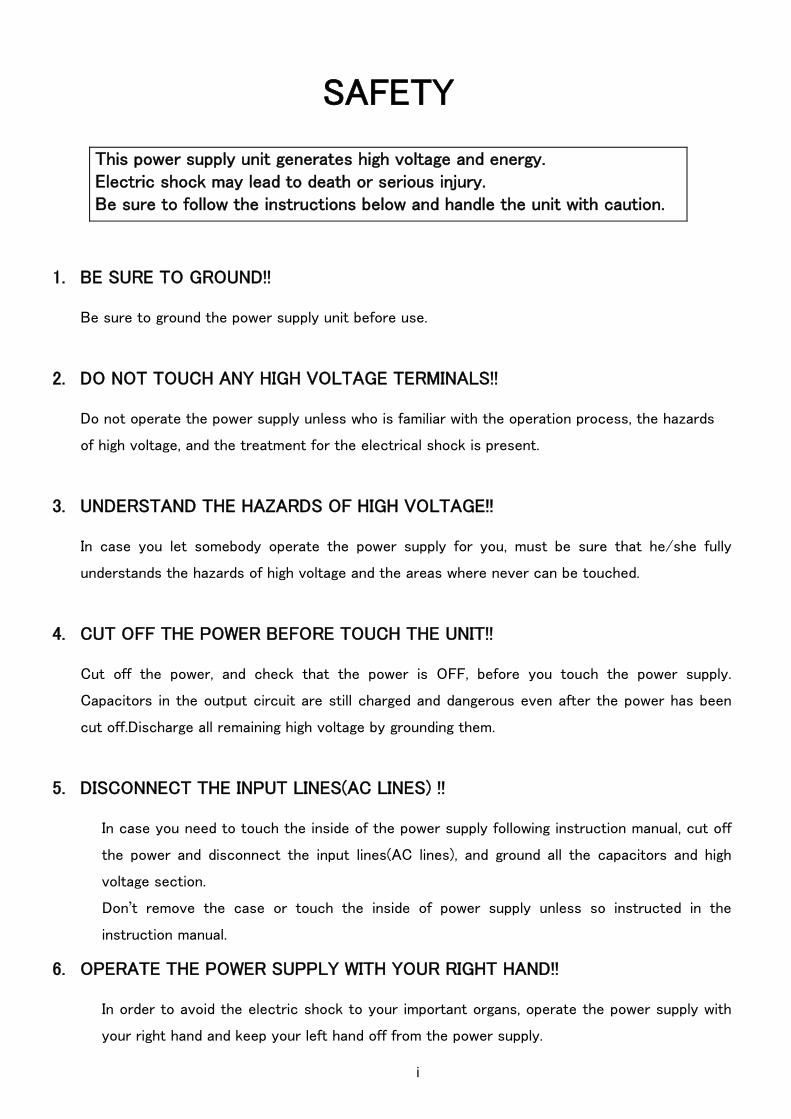
SAFETY
1. BE SURE TO GROUND!!
Be sure to ground the power supply unit before use.
2. DO NOT TOUCH ANY HIGH VOLTAGE TERMINALS!!
Do not operate the power supply unless who is familiar with the operation process, the hazards
of high voltage, and the treatment for the electrical shock is present.
3. UNDERSTAND THE HAZARDS OF HIGH VOLTAGE!!
In case you let somebody operate the power supply for you, must be sure that he/she fully
understands the hazards of high voltage and the areas where never can be touched.
4. CUT OFF THE POWER BEFORE TOUCH THE UNIT!!
Cut off the power, and check that the power is OFF, before you touch the power supply.
Capacitors in the output circuit are still charged and dangerous even after the power has been
cut off.Discharge all remaining high voltage by grounding them.
5. DISCONNECT THE INPUT LINES(AC LINES) !!
In case you need to touch the inside of the power supply following instruction manual, cut off
the power and disconnect the input lines(AC lines), and ground all the capacitors and high
voltage section.
Don’t remove the case or touch the inside of power supply unless so instructed in the
instruction manual.
6. OPERATE THE POWER SUPPLY WITH YOUR RIGHT HAND!!
In order to avoid the electric shock to your important organs, operate the power supply with
your right hand and keep your left hand off from the power supply.
This power supply unit generates high voltage and energy. Electric shock may lead to death or serious injury. Be sure to follow the instructions below and handle the unit with caution.
ⅱ
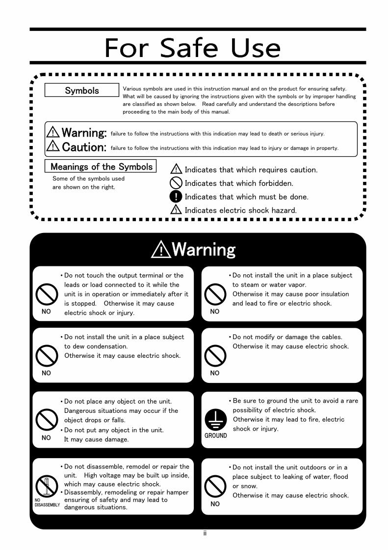
Various symbols are used in this instruction manual and on the product for ensuring safety.
What will be caused by ignoring the instructions given with the symbols or by improper handling
are classified as shown below. Read carefully and understand the descriptions before
proceeding to the main body of this manual.
Symbols
Meanings of the Symbols Some of the symbols used
are shown on the right.
Indicates that which requires caution.
Indicates that which forbidden.
Indicates that which must be done.
Indicates electric shock hazard.
failure to follow the instructions with this indication may lead to death or serious injury.
failure to follow the instructions with this indication may lead to injury or damage in property.
Warning: Caution:
!
!
!
!
!WarningDo not touch the output terminal or the
leads or load connected to it while the
unit is in operation or immediately after it
is stopped. Otherwise it may cause
electric shock or injury.
Do not install the unit in a place subject
to steam or water vapor.
Otherwise it may cause poor insulation
and lead to fire or electric shock.
Do not install the unit in a place subject
to dew condensation.
Otherwise it may cause electric shock.
Do not modify or damage the cables.
Otherwise it may cause electric shock.
Be sure to ground the unit to avoid a rare
possibility of electric shock.
Otherwise it may lead to fire, electric
shock or injury.
Do not place any object on the unit.
Dangerous situations may occur if the
object drops or falls.
Do not put any object in the unit.
It may cause damage.
Do not disassemble, remodel or repair the unit. High voltage may be built up inside, which may cause electric shock. Disassembly, remodeling or repair hamper ensuring of safety and may lead to dangerous situations.
Do not install the unit outdoors or in a
place subject to leaking of water, flood
or snow.
Otherwise it may cause electric shock.
NO
NO
NO
NO DISASSEMBLY
NO
NO
GROUND
NO

ⅲ
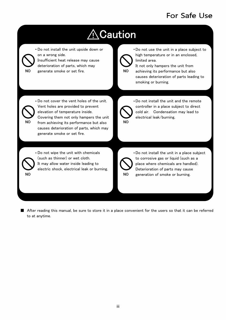
■ After reading this manual, be sure to store it in a place convenient for the users so that it can be referred
to at anytime.
!CautionDo not install the unit upside down or
on a wrong side.
Insufficient heat release may cause
deterioration of parts, which may
generate smoke or set fire.
Do not use the unit in a place subject to
high temperature or in an enclosed,
limited area.
It not only hampers the unit from
achieving its performance but also
causes deterioration of parts leading to
smoking or burning.
Do not wipe the unit with chemicals
(such as thinner) or wet cloth.
It may allow water inside leading to
electric shock, electrical leak or burning.
Do not cover the vent holes of the unit.
Vent holes are provided to prevent
elevation of temperature inside.
Covering them not only hampers the unit
from achieving its performance but also
causes deterioration of parts, which may
generate smoke or set fire.
Do not install the unit and the remote
controller in a place subject to direct
cold air. Condensation may lead to
electrical leak/burning.
Do not install the unit in a place subject
to corrosive gas or liquid (such as a
place where chemicals are handled).
Deterioration of parts may cause
generation of smoke or burning.
NO NO
NO NO
NO NO
ⅳ
(1) RESCUE
FREE VICTIM FROM CONTACT WITH LIVE CONDUCTOR QUICKLY.
AVOID CONTACT WITH FITHER LIVE CONDUCTOR OR VICTIM’S BODY.
Shut off high voltage at once and ground circuit. If high voltage cannot be turned off
quickly, ground circuit.
An ax with a dry wooden handle may be used to cut high voltage line.
Use extreme caution to avoid resulting electric flash.
If circuit cannot be broken or grounded, use a dry board, dry clothing, or other
nonconductor to free victim.
(2) SYMPTOMS
NEVER ACCEPT ORIDNARY AND GENERAL TESTS FOR DEATH.
Symptoms of electric shock may include unconsciousness, failure to breathe, absence of
pulse, pallor, and stiffness, as well as severe burns.
WHENEVER VICTIM IS NOT BREATING PROPERLY, GIVE ARTIFICIAL RESPIRATION.
(3) TREATMENT
START ARTIFICIAL RESPIRAITON IMMEDIATELY.
Perform artificial respiration at scene of accident, unless victim’s or operator’s life is
endangered. IN THIS CASE ONLY, remove victim to safe location nearby, if new location
is more than few feet away, give artificial respiration while victim is being moved.
After starting artificial respiration, continue without loss of rhythm for at least FOUR
HOURS, or until victim is breathing without help.
If you have to change operators while giving artificial respiration, do so without losing
rhythm of respiration.
(4) AFTER VICTIM REVIVES
Be prepared to resume artificial respiration, as he may stop breathing again.
When victim is CONPLETELY CONSCIOUS, give him a stimulant (NOT AN ALCOHOLIC
DRINK) such as teaspoonful of aromatic spirits of ammonia in a small glass of water, hot
coffee, or hot tea.
Keep victim warm and lying down until he has been conscious for at least fifteen minutes.
First-aid procedures to be implemented in case of electrical shock

ⅴ
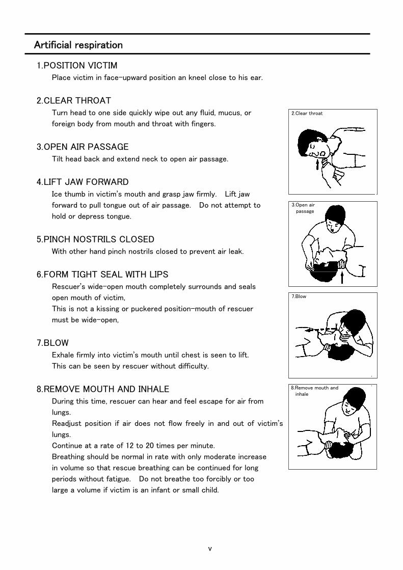
1. POSITION VICTIM Place victim in face-upward position an kneel close to his ear.
2. CLEAR THROAT Turn head to one side quickly wipe out any fluid, mucus, or
foreign body from mouth and throat with fingers.
3. OPEN AIR PASSAGE Tilt head back and extend neck to open air passage.
4. LIFT JAW FORWARD Ice thumb in victim’s mouth and grasp jaw firmly. Lift jaw
forward to pull tongue out of air passage. Do not attempt to
hold or depress tongue.
5. PINCH NOSTRILS CLOSED With other hand pinch nostrils closed to prevent air leak.
6. FORM TIGHT SEAL WITH LIPS Rescuer’s wide-open mouth completely surrounds and seals
open mouth of victim,
This is not a kissing or puckered position-mouth of rescuer
must be wide-open,
7. BLOW Exhale firmly into victim’s mouth until chest is seen to lift.
This can be seen by rescuer without difficulty.
8. REMOVE MOUTH AND INHALE During this time, rescuer can hear and feel escape for air from
lungs.
Readjust position if air does not flow freely in and out of victim’s
lungs.
Continue at a rate of 12 to 20 times per minute.
Breathing should be normal in rate with only moderate increase
in volume so that rescue breathing can be continued for long
periods without fatigue. Do not breathe too forcibly or too
large a volume if victim is an infant or small child.
8.Remove mouth and inhale
7.Blow
3.Open air passage
2.Clear throat
Artificial respiration
1
1-1 Introduction
Thank you very much for your purchase of our product, HIGH VOLTAGE POWER SUPPLY.
We do our best to exercise quality control of our products. You will please handle this unit
properly according to this operation manual so that you may display the full capacity of this
unit, operate it for smoothly in high efficiency for many years to come and safely.
We have done our best to prepare this operation but if you should recognize a doubtful or
unknown point or an omission, we are very sorry but would you please contact our company
immediately.
1-2 Unpacking the High Voltage Power Supply
When unpacked, you will please check the following accessories are enclosed together with
the power supply body.
〈Accessories〉
・ Instruction Manual
・ Output cable
・ Connector Screw terminal 2pin
Screw terminal 3pin
Screw terminal 4pin
D-type connector 9pin
・ Screw 2pc.
1-3 Environmental requirements
・ Install a high voltage power supply horizontally and use it.
・ Never place an object on the high voltage power supply.
・ Provide an ample space to the upper, right and left side of the high voltage power supply.
Use it at the place where the ventilating condition is as good as possible.
・ Avoid using the unit at such places where it is very dusty or there is much corrosive gas
etc.
1 Introduction
1 Introduction
(1pc.)
2
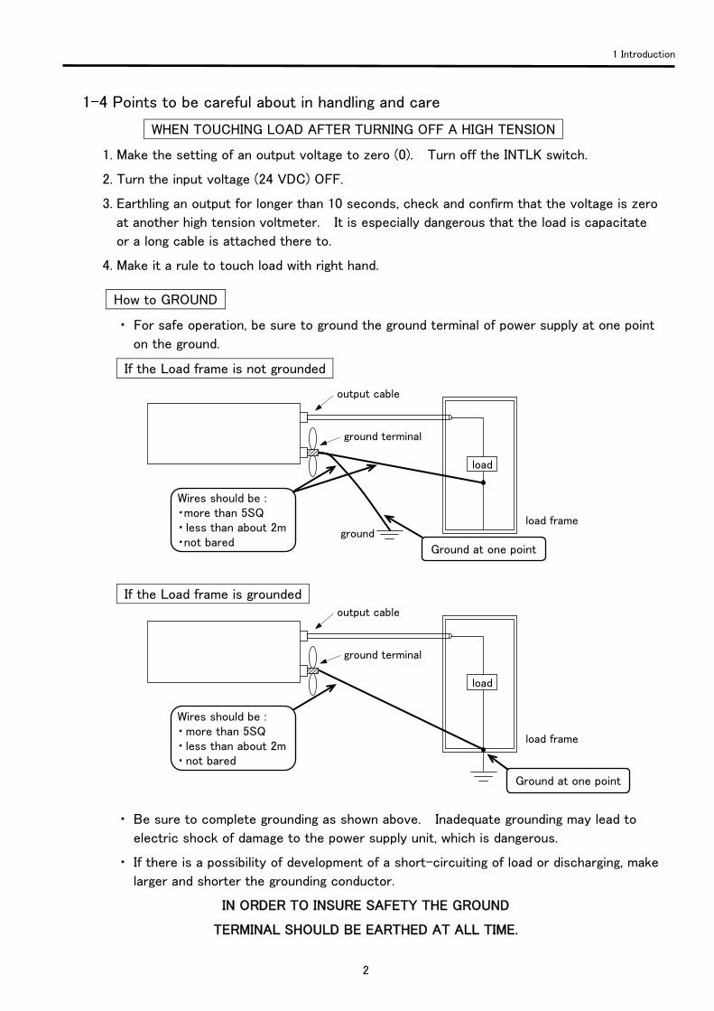
1-4 Points to be careful about in handling and care
WHEN TOUCHING LOAD AFTER TURNING OFF A HIGH TENSION
1. Make the setting of an output voltage to zero (0). Turn off the INTLK switch.
2. Turn the input voltage (24 VDC) OFF.
3. Earthling an output for longer than 10 seconds, check and confirm that the voltage is zero
at another high tension voltmeter. It is especially dangerous that the load is capacitate
or a long cable is attached there to.
4. Make it a rule to touch load with right hand. How to GROUND
・ For safe operation, be sure to ground the ground terminal of power supply at one point
on the ground.
If the Load frame is not grounded
If the Load frame is grounded
・ Be sure to complete grounding as shown above. Inadequate grounding may lead to
electric shock of damage to the power supply unit, which is dangerous.
・ If there is a possibility of development of a short-circuiting of load or discharging, make
larger and shorter the grounding conductor.
IN ORDER TO INSURE SAFETY THE GROUND
TERMINAL SHOULD BE EARTHED AT ALL TIME.
1 Introduction
output cable
ground terminal
load frame
load
Wires should be : ・ more than 5SQ ・ less than about 2m ・ not bared
Ground at one point
Wires should be : ・more than 5SQ ・ less than about 2m ・not bared
output cable
ground terminal
ground load frame
load
Ground at one point
3
FOR SAFER OPERATION
1. Laying an insulation plate which can withstand the voltage to be used on the floor on
which an operator stands, carry out the operation. If done so, it will be comparatively
safe.
2. When operating a power supply and load, do so with right hand with left hand put in the
pocket, taking care not to touch other objects.
3. After turning off the voltage (even if a long time has lapsed after turning off), if you
touch load, be sure to earth the output longer than 10 seconds.
1-5 What to do before calling for service
・ In case no output voltage is generated.
1. Check whether or not a specified voltage has been inputted.
・ Input Voltage +24Vdc ±10%
・ Control voltage 0 – 10V at the time of controlling over external voltage.
・ Control voltage 0 – 10V at the time of controlling over external current.
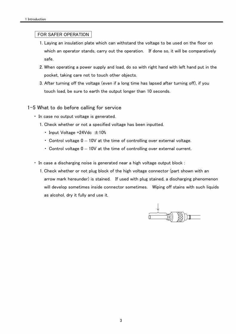
・ In case a discharging noise is generated near a high voltage output block :
1. Check whether or not plug block of the high voltage connector (part shown with an
arrow mark hereunder) is stained. If used with plug stained, a discharging phenomenon
will develop sometimes inside connector sometimes. Wiping off stains with such liquids
as alcohol, dry it fully and use it.
1 Introduction
4
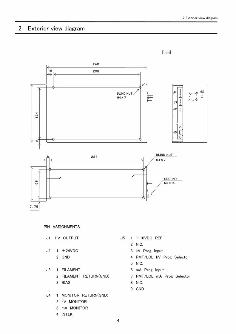
PIN ASSIGNMENTS
J1 HV OUTPUT J5 1 +10VDC REF
2 N.C.
J2 1 +24VDC 3 kV Prog Input
2 GND 4 RMT/LCL kV Prog Selector
5 N.C.
J3 1 FILAMENT 6 mA Prog Input
2 FILAMENT RETURN(GND) 7 RMT/LCL mA Prog Selector
3 BIAS 8 N.C.
9 GND
J4 1 MONITOR RETURN(GND)
2 kV MONITOR
3 mA MONITOR
4 INTLK
2 Exterior view diagram
2 Exterior view diagram
J3
J2
J4
J5
8
240
208 16
8
7.75
12
4
68
224
GROUND
M5×15
BLIND NUT
M4×7
BLIND NUT
M4×7
[mm]
5
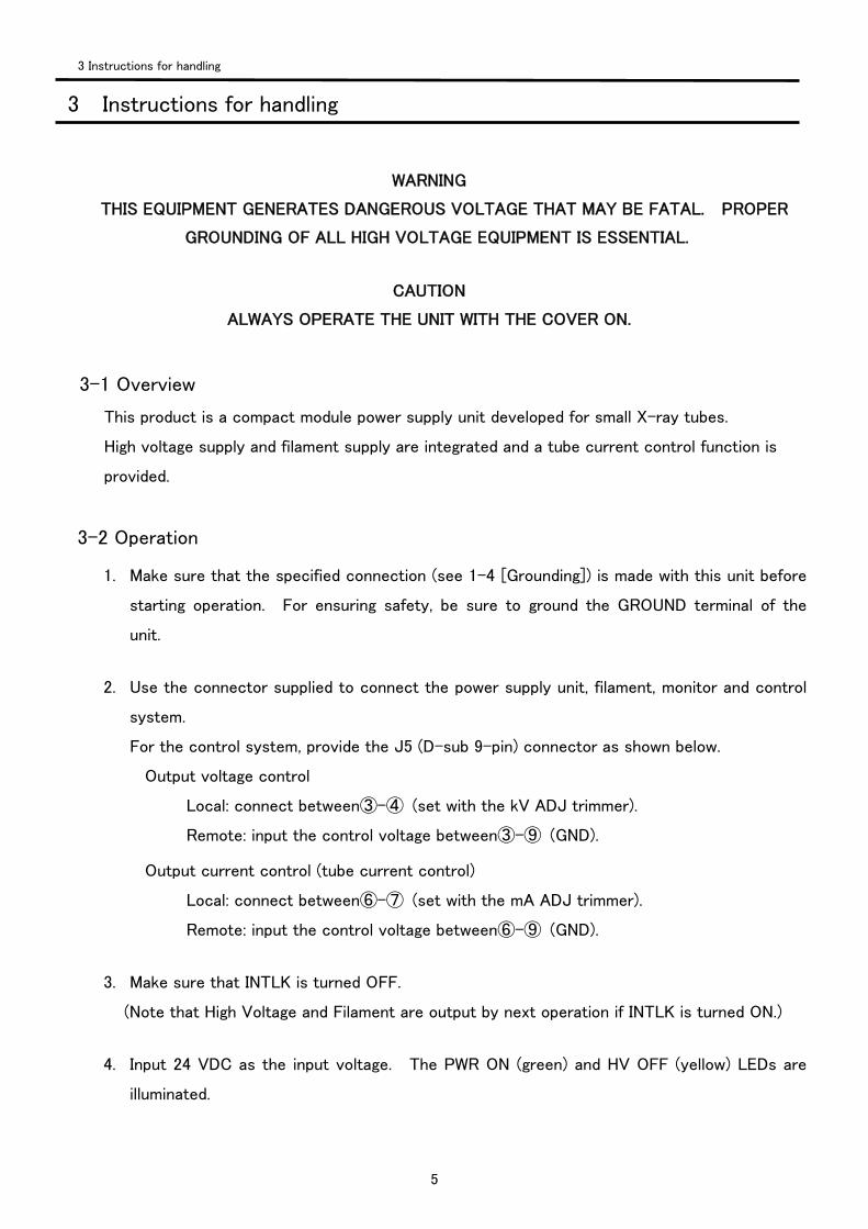
WARNING
THIS EQUIPMENT GENERATES DANGEROUS VOLTAGE THAT MAY BE FATAL. PROPER
GROUNDING OF ALL HIGH VOLTAGE EQUIPMENT IS ESSENTIAL.
CAUTION
ALWAYS OPERATE THE UNIT WITH THE COVER ON.
3-1 Overview
This product is a compact module power supply unit developed for small X-ray tubes.
High voltage supply and filament supply are integrated and a tube current control function is
provided.
3-2 Operation
1. Make sure that the specified connection (see 1-4 [Grounding]) is made with this unit before
starting operation. For ensuring safety, be sure to ground the GROUND terminal of the
unit.
2. Use the connector supplied to connect the power supply unit, filament, monitor and control
system.
For the control system, provide the J5 (D-sub 9-pin) connector as shown below.
Output voltage control
Local: connect between③-④ (set with the kV ADJ trimmer).
Remote: input the control voltage between③-⑨ (GND). Output current control (tube current control)
Local: connect between⑥-⑦ (set with the mA ADJ trimmer).
Remote: input the control voltage between⑥-⑨ (GND).
3. Make sure that INTLK is turned OFF.
(Note that High Voltage and Filament are output by next operation if INTLK is turned ON.)
4. Input 24 VDC as the input voltage. The PWR ON (green) and HV OFF (yellow) LEDs are
illuminated.
3 Instructions for handling
3 Instructions for handling
6
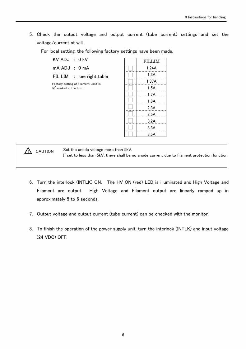
5. Check the output voltage and output current (tube current) settings and set the
voltage/current at will.
For local setting, the following factory settings have been made.
KV ADJ : 0 kV
mA ADJ : 0 mA
FIL LIM : see right table
6. Turn the interlock (INTLK) ON. The HV ON (red) LED is illuminated and High Voltage and
Filament are output. High Voltage and Filament output are linearly ramped up in
approximately 5 to 6 seconds.
7. Output voltage and output current (tube current) can be checked with the monitor.
8. To finish the operation of the power supply unit, turn the interlock (INTLK) and input voltage
(24 VDC) OFF.
3 Instructions for handling
Factory setting of Filament Limit is
□ marked in the box.
Set the anode voltage more than 5kV.
If set to less than 5kV, there shall be no anode current due to filament protection function! CAUTION
FILLIM 1.24A
1.3A
1.37A
1.5A
1.7A
1.8A
2.3A
2.5A
3.2A
3.3A
3.5A
7
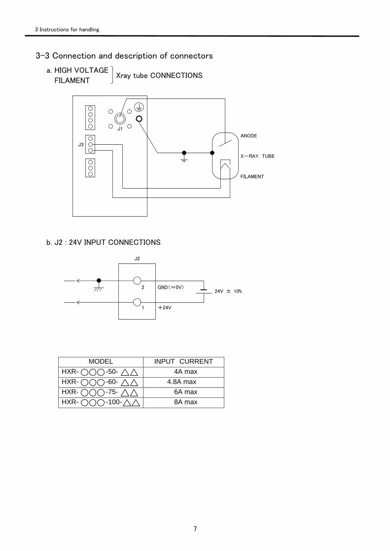
3-3 Connection and description of connectors
a. HIGH VOLTAGE
FILAMENT
b. J2 : 24V INPUT CONNECTIONS
MODEL INPUT CURRENT HXR- -50- 4A max HXR- -60- 4.8A max HXR- -75- 6A max HXR- -100- 8A max
3 Instructions for handling
J3
J1
ANODE
X-RAY TUBE
FILAMENT
Xray tube CONNECTIONS
J2
GND(=0V)
+24V
2
1
24V ± 10%
8
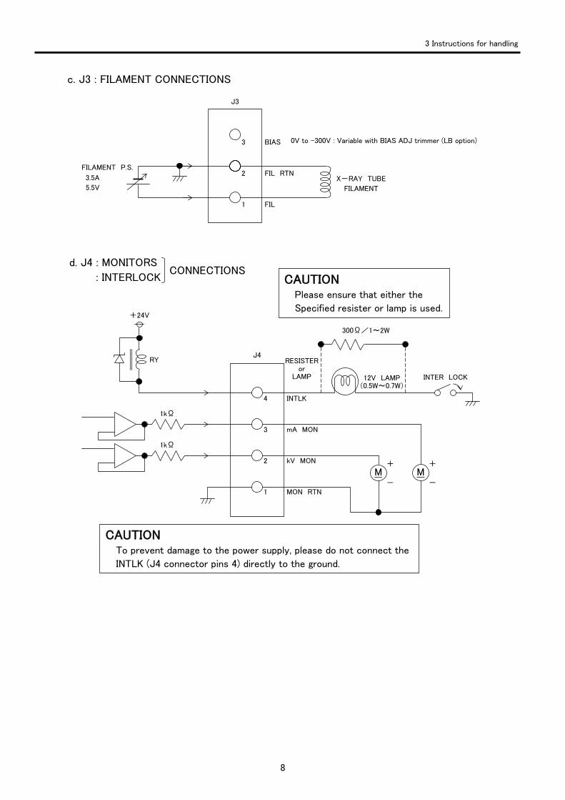
c. J3 : FILAMENT CONNECTIONS
d. J4 : MONITORS
: INTERLOCK
3 Instructions for handling
CONNECTIONS
J3
BIAS
FIL RTN
FIL
3
2
1
X-RAY TUBE
FILAMENT
FILAMENT P.S.
3.5A
5.5V
M + -
J4
INTLK
mA MON
kV MON
MON RTN
4
3
2
1
+24V
1kΩ
1kΩ
RY RESISTERor
LAMP 12V LAMP (0.5W~0.7W)
INTER LOCK
M+
-
300Ω/1~2W
CAUTION Please ensure that either the
Specified resister or lamp is used.
CAUTION To prevent damage to the power supply, please do not connect the
INTLK (J4 connector pins 4) directly to the ground.
0V to –300V : Variable with BIAS ADJ trimmer (LB option)
9
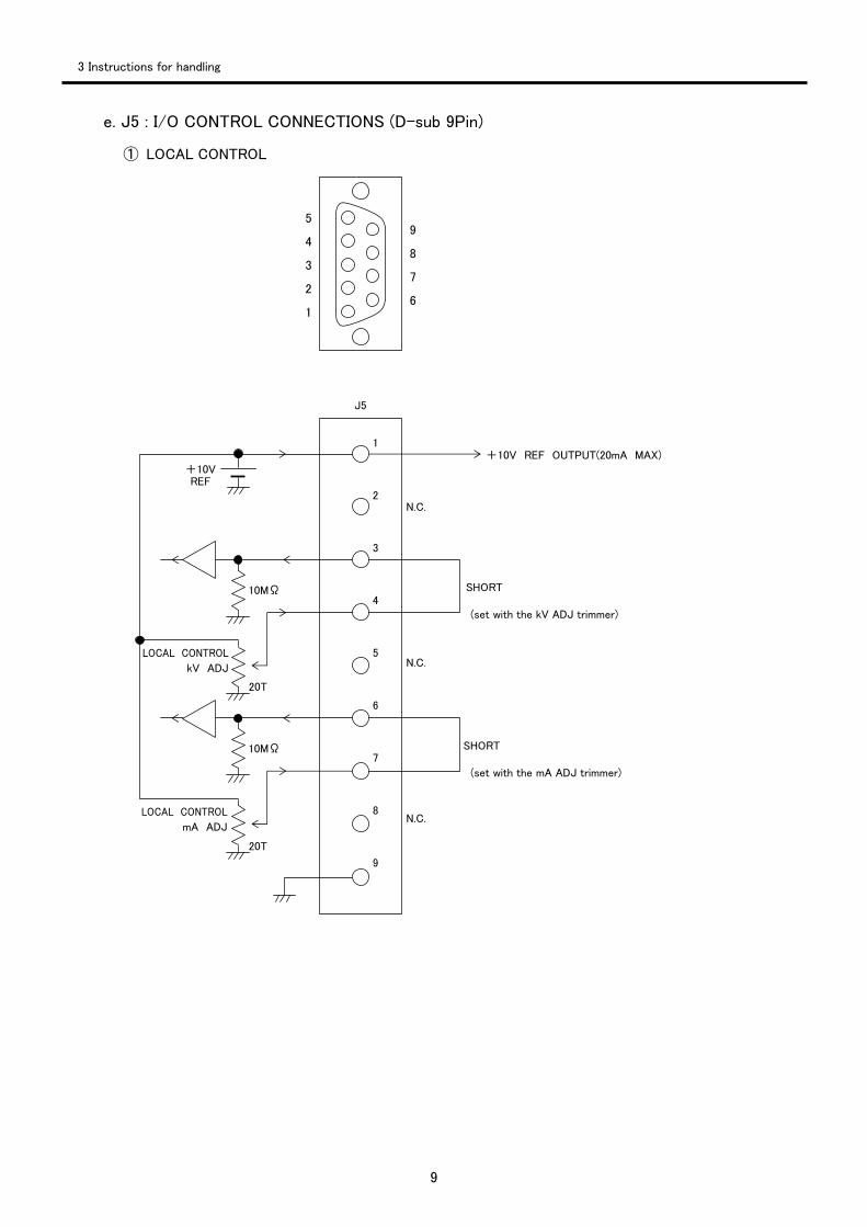
e. J5 : I/O CONTROL CONNECTIONS (D-sub 9Pin)
① LOCAL CONTROL
5
4
3
2
1
9
8
7
6
1
2
3
4
5
6
7
8
9
J5
+10V REF OUTPUT(20mA MAX) +10V REF
10MΩ
10MΩ
LOCAL CONTROL
kV ADJ
20T
LOCAL CONTROL
mA ADJ
20T
N.C.
N.C.
N.C.
SHORT
(set with the kV ADJ trimmer)
SHORT
(set with the mA ADJ trimmer)
3 Instructions for handling
10
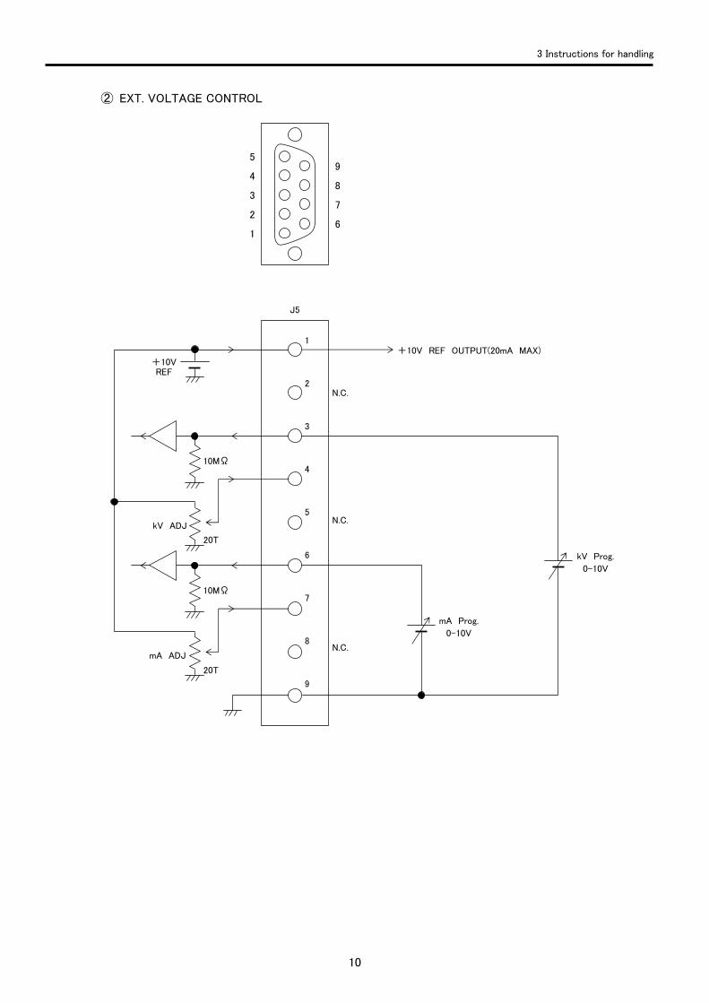
② EXT. VOLTAGE CONTROL
3 Instructions for handling
5
4
3
2
1
9
8
7
6
1
2
3
4
5
6
7
8
9
J5
+10V REF OUTPUT(20mA MAX) +10V REF
10MΩ
10MΩ
kV ADJ
20T
mA ADJ
20T
N.C.
N.C.
N.C.
mA Prog.
0-10V
kV Prog.
0-10V
11
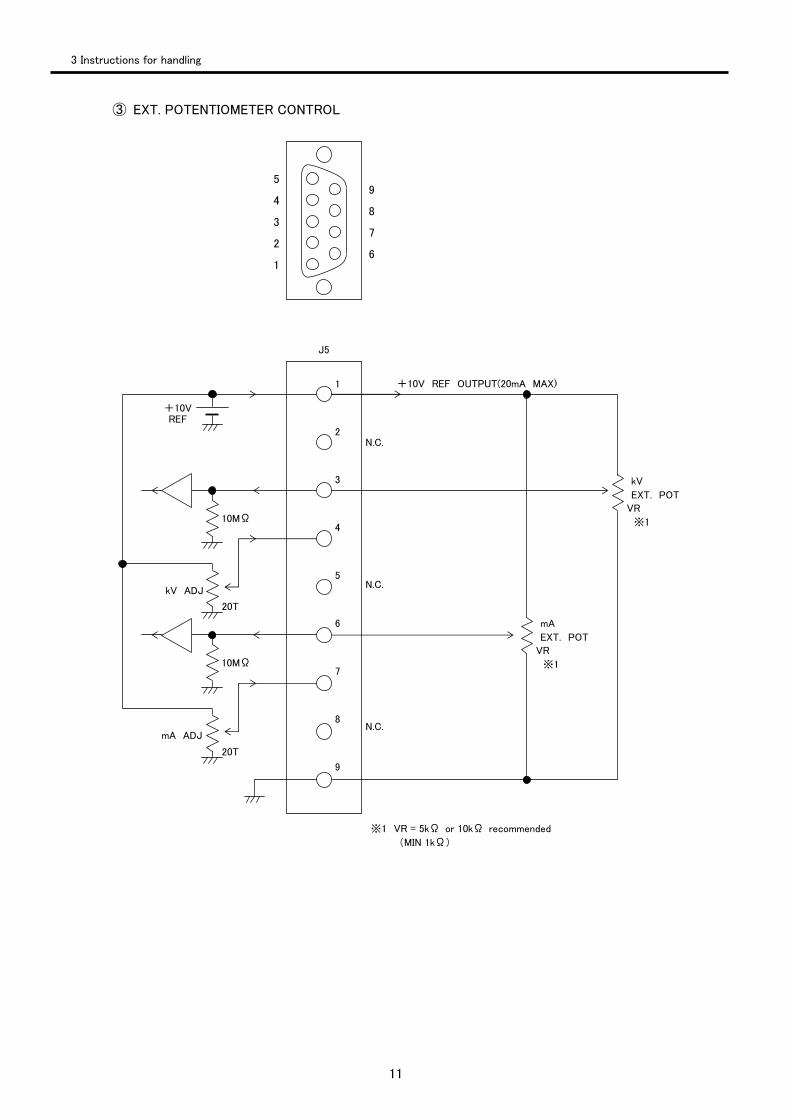
③ EXT. POTENTIOMETER CONTROL
3 Instructions for handling
5
4
3
2
1
9
8
7
6
1
2
3
4
5
6
7
8
9
J5
+10V REF OUTPUT(20mA MAX)
+10V REF
10MΩ
10MΩ
kV ADJ
20T
mA ADJ
20T
N.C.
N.C.
N.C.
mA
EXT. POT
VR
※1
kV
EXT. POT
VR
※1
※1 VR = 5kΩ or 10kΩ recommended
(MIN 1kΩ)

12
3-5 Option
Bias Supply Output terminal J3-3 Via internal multi-turn potentiometer (BIAS ADJ) 0 to –300V, adjustable. Load current is 0.25mA, load regulation is 1% The unit will be preset to 0V prior to shipment.
3 Instructions for handling