instruction manual mm-323f - xylem applied...
TRANSCRIPT

INSTRUCTION MANUAL MM-323F

PowerModel Voltage** Consumption*
WFE-24 24VAC 15VAWFE-120 120VAC 20VA
WATER FEEDER INLETVALVE
OUTLETVALVE
UNION
UNIONSTRAINER
CITYWATER SUPPLY
CHECKVALVE
BYPASSVALVE
UNION
BYPASS
CONNECT TORETURN HEADER
ON BOILER
2
1 a. Control must be installed within eyesight of boiler.b. Clearance must be provided on all sides to
service control.c. Unit must be installed in a horizontal pipe
in an upright position.d. Arrow on feeder must point in the
direction of flow into the boiler.e. Install isolation valves and unions on the
inlet and outlet piping for easier trouble shooting and repair/replacement.
f. Install manual fill valve and bypass line forremoval while the boiler is in service.
2. Water feeders are shipped from the factory equipped for a 2 gpm feed rate. A separate kit with instruction sheet and field installable orifices for 1 gpm and 4 gpm feed rates is included. If the alternate feed rates are required, refer to the instruction sheet provided with the kit for orifice replacement.
1 GPMOrifice
4 GPMOrifice
Dwell/FeedSelector Switch
Multi Function
LED
ManualFeed
Button
234
1
ONSW1
OFF
SPECIFICATIONSMaximum Water Pressure:
150 psi (10.5 kg/cm2)Maximum Boiler Pressure:
15 psi (1 kg/cm2)Pipe Connections:
3/8" NPT (sweat adapters included for connection to 1/2" copper pipe)
Flow Data:2 gpm (7.6 lpm) standardOrifices included to change feed rate to 1 gpm (3.8 lpm) or 4 gpm (15.1 lpm)
Maximum Water Temperature:120 F (49 C)
Maximum Ambient Temperature:100˚F (38˚C)
Dwell/Feed Selector SwitchThe water feeder has a DIP type switch block withfour on/off switches. Each switch has a specificdwell/feed cycle which is activated upon receivinga signal from the LWCO. The feeder will be deacti-vated when the LWCO is satisfied or if thedwell/feed period has been exceeded.
Manual FeedThere is a manual feed button which when pressedwill add water to the boiler.
Multi-Color LEDA multi-color LED indicates status during operation,incorrect switch selection and when dwell/feedcycle has been exceeded.
Dwell/Feed Cycle LimitThe feeder will stop feeding water whenever theselected dwell/feed cycle time has been exceededand the LWCO is still sending a signal.
STEP 1 - Installation
Electrical Ratings
* During Feed Cycle** 50/60 Hz
o o

3
Boiler manufacturer schematics should be followed. Inthe event that the boiler manufacturer's schematic doesnot exist, or is not available from the boiler manufacturer,refer to the schematics provided in this document.
IMPORTANTTo prevent electrical shock, turn off theelectrical power before making electricalconnections.Failure to follow this warning could causeproperty damage, personal injury or death.
WARNING
Terminal Connections
N
P
M
For all wire connections to the terminal block (M).1. Strip about 1/3" (8.5 mm) of insulation from the wire.2. Loosen the terminal screw (N) but DO NOT
REMOVE. Move the wire clamping plate (P) back until the plate touches the back side of the screw head.
3. Insert the stripped end of the wire under the wire clamping plate (P) and securely tighten the terminal screw (N).
Do not use automatic water feeders with manual resetLWCO's. Failure to follow this warning could causeflooding, property damage, personal injury or death.
WARNINGUnless otherwise noted, water feeder voltage should bethe same as the LWCO and burner circuit voltage.
NOTE
Before wiring water feeder, operate boiler and check allsafety devices.
NOTEWire must be 18 AWG (min) or as required by local code.Wire insulation rating must be at least 167˚F (75˚C)
NOTE
STEP 2 - Electrical Installation
Feeder Model LWCO Model Diagram Number Page
WFE-24 PS-802 with burner wiring harness 1 4WFE-24 PS-802 with burner terminal connections 1 4WFE-24 67 w/24 volt burner circuit 4 4WFE-24 67 w/120 volt burner circuit 6 4WFE-24 67G (millivolt burner circuit) 9 5
WFE-120 PS-801 with numbered terminals 2 4
WFE-120 PS-801 with lettered terminals 3 4WFE-120 67 w/24 volt burner circuit 7 4WFE-120 67 w/120 volt burner circuit 5 4WFE-120 67G (millivolt burner circuit) 8 5WFE-24 Hydrolevel 400 10 5WFE-24 Hydrolevel CG400 11 5WFE-120 Hydrolevel 450 12 5WFE-120 Hydrolevel CG450 13 5WFE-120 Hydrolevel CGT450 14 6WFE-24 Honeywell LWCO (24 volt) 15 6WFE-120 Honeywell LWCO (120 volt) 16 6WFE-24 TACO LWCO (24 volt) 18 6WFE-120 TACO LWCO (120 volt) 17 6
Wiring Diagram Selection Chart
Based on the water feeder and low water cut-off combination you are installing, select proper wiring diagram and proceed to that page.
WFE-24 PSE-802 with burner wiring harness 1 4
WFE-24 PSE-802 with burner terminal connections 1 4
WFE-120 PSE-801 with lettered terminals 3 4
4
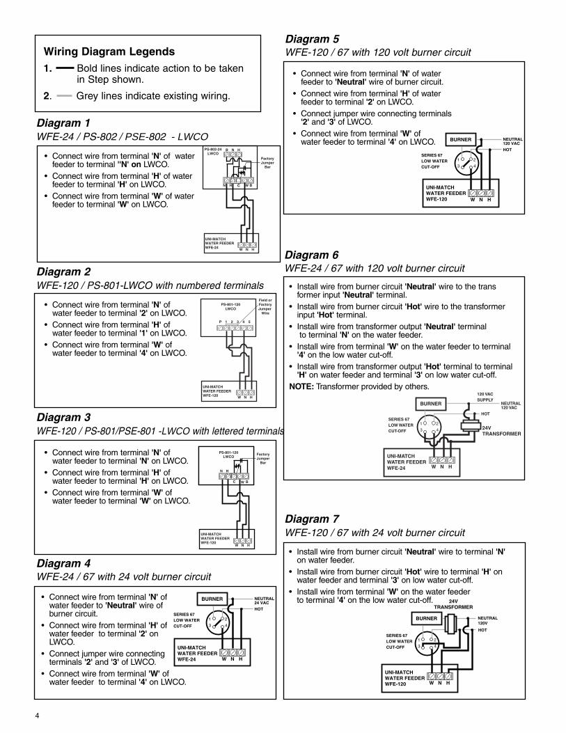
Wiring Diagram Legends1. Bold lines indicate action to be taken
in Step shown.
2. Grey lines indicate existing wiring.
PS-802-24LWCO
B N H
UNI-MATCHWATER FEEDERWFE-24
FactoryJumper
Bar
W N H
• Connect wire from terminal 'N' of waterfeeder to terminal ''N' on LWCO.
• Connect wire from terminal 'H' of water feeder to terminal 'H' on LWCO.
• Connect wire from terminal 'W' of waterfeeder to terminal 'W' on LWCO.
Diagram 1 WFE-24 / PS-802 / PSE-802 - LWCO
W N H
PS-801-120LWCO
UNI-MATCHWATER FEEDERWFE-120
Field orFactoryJumper
Wire
P 1 2 3 4 5
• Connect wire from terminal 'N' of water feeder to terminal '2' on LWCO.
• Connect wire from terminal 'H' of water feeder to terminal '1' on LWCO.
• Connect wire from terminal 'W' of water feeder to terminal '4' on LWCO.
Diagram 2 WFE-120 / PS-801-LWCO with numbered terminals
PS-801-120LWCO
UNI-MATCHWATER FEEDERWFE-120
N H
W N H
FactoryJumper
Bar
• Connect wire from terminal 'N' of water feeder to terminal 'N' on LWCO.
• Connect wire from terminal 'H' of water feeder to terminal 'H' on LWCO.
• Connect wire from terminal 'W' of water feeder to terminal 'W' on LWCO.
Diagram 3 WFE-120 / PS-801/PSE-801 -LWCO with lettered terminals
W N H
BURNER
1 2
3 4
NEUTRAL24 VAC
HOT
UNI-MATCHWATER FEEDERWFE-24
SERIES 67LOW WATERCUT-OFF
• Connect wire from terminal 'N' of water feeder to 'Neutral' wire of burner circuit.
• Connect wire from terminal 'H' of water feeder to terminal '2' on LWCO.
• Connect jumper wire connecting terminals '2' and '3' of LWCO.
• Connect wire from terminal 'W' of water feeder to terminal '4' on LWCO.
Diagram 4 WFE-24 / 67 with 24 volt burner circuit
W N H
BURNER
1 2
3 4
NEUTRAL120 VAC
HOT
UNI-MATCHWATER FEEDERWFE-120
SERIES 67LOW WATERCUT-OFF
• Connect wire from terminal 'N' of water feeder to 'Neutral' wire of burner circuit.
• Connect wire from terminal 'H' of water feeder to terminal '2' on LWCO.
• Connect jumper wire connecting terminals '2' and '3' of LWCO.
• Connect wire from terminal 'W' of water feeder to terminal '4' on LWCO.
Diagram 5 WFE-120 / 67 with 120 volt burner circuit
W N H
BURNER
24VTRANSFORMER
1 2
3 4
NEUTRAL120 VAC
120 VACSUPPLY
HOT
UNI-MATCHWATER FEEDERWFE-24
SERIES 67LOW WATERCUT-OFF
• Install wire from burner circuit 'Neutral' wire to the transformer input 'Neutral' terminal.
• Install wire from burner circuit 'Hot' wire to the transformer input 'Hot' terminal.
• Install wire from transformer output 'Neutral' terminalto terminal 'N' on the water feeder.
• Install wire from terminal 'W' on the water feeder to terminal '4' on the low water cut-off.
• Install wire from transformer output 'Hot' terminal to terminal 'H' on water feeder and terminal '3' on low water cut-off.
NOTE: Transformer provided by others.
Diagram 6 WFE-24 / 67 with 120 volt burner circuit
W N H
BURNER
24VTRANSFORMER
1 2
3 4
NEUTRAL120V
HOT
UNI-MATCHWATER FEEDERWFE-120
SERIES 67LOW WATERCUT-OFF
• Install wire from burner circuit 'Neutral' wire to terminal 'N'on water feeder.
• Install wire from burner circuit 'Hot' wire to terminal 'H' on water feeder and terminal '3' on low water cut-off.
• Install wire from terminal 'W' on the water feeder to terminal '4' on the low water cut-off.
Diagram 7 WFE-120 / 67 with 24 volt burner circuit
C W B
N H C W B

5
W N H
MILLIVOLTBURNERCIRCUIT
1 2
3 4NEUTRAL
HOT120V
UNI-MATCHWATER FEEDERWFE-120
SERIES 67LOW WATERCUT-OFF
• Install wire from 120 volt circuit 'Neutral' wire to terminal 'N'on water feeder.
• Install wire from 120 volt circuit 'Hot' wire to terminal 'H' on water feeder and terminal '3' on low water cut-off.
• Install wire from terminal 'W' on the water feeder to terminal '4' on the low water cut-off.
Diagram 8 WFE-120 / 67 with millivolt burner circuit
W N H
MILLIVOLTBURNERCIRCUIT
1 2
3 4
NE
UT
RA
L
HO
T
24V
TRANSFORMER
120V
UNI-MATCHWATER FEEDERWFE-24
SERIES 67LOW WATERCUT-OFF
• Install wire from 120 volt circuit 'Neutral' wire to the transformer input 'Neutral' terminal.
• Install wire from 120 volt circuit 'Hot' wire to the transformer input 'Hot' terminal.
• Install wire from transformer output 'Neutral'terminal to terminal 'N' on the water feeder.
• Install wire from transformer output 'Hot' terminalto terminal 'H' on water feeder and terminal '3' onlow water cut-off.
• Install wire from terminal 'W' on the water feeder to terminal '4' on the low water cut-off.
NOTE: Transformer provided by others.
Diagram 9 WFE-24 / 67 with millivolt burner circuit
UNI-MATCHWATER FEEDERWFE-24
2 1 P1 P2 A
W N H
HYDROLEVEL 400 FactoryJumper
Bar
• Connect wire from terminal 'N' of water feeder to terminal '2' on LWCO.
• Connect wire from terminal 'H' of water feeder to terminal '1' on LWCO.
• Connect wire from terminal 'W' of water feeder to terminal 'A' on LWCO.
Diagram 10WFE-24 / Hydrolevel 400
UNI-MATCHWATER FEEDERWFE-24
2 1 P1 P2 A
W N H
HYDROLEVEL CG400 FactoryJumper
BarBURNER
• Connect wire from terminal 'N' of water feeder to terminal '2' on LWCO.
• Connect wire from terminal 'H' of water feeder to terminal '1' on LWCO.
• Connect wire from terminal 'W' of water feeder to terminal 'A' on LWCO.
Diagram 11 WFE-24 / Hydrolevel CG400
UNI-MATCHWATER FEEDERWFE-120
2 1 P1 P2 A
W N H
FactoryJumper
Bar
HYDROLEVEL 450
• Connect wire from terminal 'N' of water feeder to terminal '2' on LWCO.
• Connect wire from terminal 'H' of water feeder to terminal '1' on LWCO.
• Connect wire from terminal 'W' of water feeder to terminal 'A' on LWCO.
Diagram 12 WFE-120 / Hydrolevel 450
UNI-MATCHWATER FEEDERWFE-120
2 1 P1 P2 A BURNER
W N H
HYDROLEVEL CG450 FactoryJumper
Bar
• Connect wire from terminal 'N' of water feeder to terminal '2' on LWCO.
• Connect wire from terminal 'H' of water feeder to terminal '1' on LWCO.
• Connect wire from terminal 'W' of water feeder to terminal 'A' on LWCO.
Diagram 13 WFE-120 / Hydrolevel CG450


7
STEP 3 - Testing
a. Open the inlet valve (X) and the outlet valve (Y). Check for any leakage.If there are any leaky connections, close the inlet and outlet valves and correct the problem.
b. Turn the boiler’s electric power on and fill it to the manufacturer's recommended normal water level by depressing the red manual feed button (Z) on the water feeder.
X
Y
FEED
INDICATOR
MANUAL
FEED
Z
B
c. Check the water feeder (B) operation by performing the following steps:1. Slowly drain water from the boiler.2. The burner should turn off when the water level drops below the cut-off level of the LWCO, which
will activate the water feeder's delay feed cycle.
3. Feeder should turn on to feed water to boiler after delay period has expired.NOTE: Delay period is determined by position of selector. Unit is shipped with switch in Position 2. Refer to chart on page 8 for alternate settings.
4. Feeder will be deactivated when water level is restored to level as determined by LWCO.NOTE: McDonnell & Miller Series PS LWCO's have a 15 second DOM (Delay on Make) to restore water level in boiler to an appropriate level without overfeeding. Consult other manufacturer's LWCO installation literature for DOM times.
5. Repeat steps to ensure feeder is operating satisfactorily.
If burner does not turn off when water level falls below level of LWCO, turnoff power to boiler and check operation of LWCO.
! WARNING
Multi-Color LEDUpon receiving a signal from LWCO (power to terminal ‘W’) the multi-color LED will indicate the statusof the feeder.
Flashing Green Dwell Period -Solenoid Closed ————
Solid Green Feed Period -Solenoid Open ————
Flashing Red Invalid Feed Cycle Switch Setting Only one of the switches should be in the ‘ON’ position.
Solid Red Dwell/Feed Cycle Exceeded Check operation of LWCO.
LED Condition Solution

Xylem Inc. 8200 N. Austin Avenue Morton Grove, Illinois 60053 Phone: (847) 966-3700 Fax: (847) 965-8379www.mcdonnellmiller.com
McDonnell & Miller is a trademark of Xylem Inc. or one of its subsidiaries. © 2015 Xylem Inc. MM-323F July 2015 Part No. 211163
COMMERCIAL WARRANTYWarranty. For goods sold to commercial buyers, Seller warrants the goods sold to Buyer hereunder (with the exception of membranes, seals, gaskets, elastomer materials, coatings and other “wear parts” or consumables all of which are not warranted except as otherwise provided in the quotation or sales form) will be (i) be built in accordance with the specifications referred to in the quotation or sales form, if such specifications are expressly made a part of this Agreement, and (ii) free from defects in material and workmanship for a period of one (1) year from the date of installation or two (2) years from the date of manufacture, whichever shall occur first, unless a longer period is specified in the product documentation (the “Warranty”).Except as otherwise required by law, Seller shall, at its option and at no cost to Buyer, either repair or replace any product which fails to conform with the Warranty provided Buyer gives written notice to Seller of any defects in material or workmanship within ten (10) days of the date when any defects or non-conformance are first manifest. Under either repair or replacement option, Seller shall not be obligated to remove or pay for the removal of the defective product or install or pay for the installation of the replaced or repaired product and Buyer shall be responsible for all other costs, including, but not limited to, service costs, shipping fees and expenses. Seller shall have sole discretion as to the method or means of repair or replacement. Buyer’s failure to comply with Seller’s repair or replacement directions shall terminate Seller’s obligations under this Warranty and render the Warranty void. Any parts repaired or replaced under the Warranty are warranted only for the balance of the warranty period on the parts that were repaired or replaced. Seller shall have no warranty obligations to Buyer with respect to any product or parts of a product that have been: (a) repaired by third parties other than Seller or without Seller’s written approval; (b) subject to misuse, misapplication, neglect, alteration, accident, or physical damage; (c) used in a manner contrary to Seller’s instructions for installation, operation and maintenance; (d) damaged from ordinary wear and tear, corrosion, or chemical attack; (e) damaged due to abnormal conditions, vibration, failure to properly prime, or operation without flow; (f) damaged due to a defective power supply or improper electrical protection; or (g) damaged resulting from the use of accessory equipment not sold or approved by Seller. In any case of products not manufactured by Seller, there is no warranty from Seller; however, Seller will extend to Buyer any warranty received from Seller’s supplier of such products.THE FOREGOING WARRANTY IS EXCLUSIVE AND IN LIEU OF ANY AND ALL OTHER EXPRESS OR IMPLIED WARRANTIES, GUARANTEES, CONDITIONS OR TERMS OF WHATEVER NATURE RELATING TO THE GOODS PROVIDED HEREUNDER, INCLUDING WITHOUT LIMITATION ANY IMPLIED WARRANTIES OF MERCHANTABILITY AND FITNESS FOR A PARTICULAR PURPOSE, WHICH ARE HEREBY EXPRESSLY DISCLAIMED AND EXCLUDED. EXCEPT AS OTHERWISE REQUIRED BY LAW, BUYER’S EXCLUSIVE REMEDY AND SELLER’S AGGREGATE LIABILITY FOR BREACH OF ANY OF THE FOREGOING WARRANTIES ARE LIMITED TO REPAIRING OR REPLACING THE PRODUCT AND SHALL IN ALL CASES BE LIMITED TO THE AMOUNT PAID BY THE BUYER FOR THE DEFECTIVE PRODUCT. IN NO EVENT SHALL SELLER BE LIABLE FOR ANY OTHER FORM OF DAMAGES, WHETHER DIRECT, INDIRECT, LIQUIDATED, INCIDENTAL, CONSEQUENTIAL, PUNITIVE, EXEMPLARY OR SPECIAL DAMAGES, INCLUDING BUT NOT LIMITED TO LOSS OF PROFIT, LOSS OF ANTICIPATED SAVINGS OR REVENUE, LOSS OF INCOME, LOSS OF BUSINESS, LOSS OF PRODUCTION, LOSS OF OPPORTUNITY OR LOSS OF REPUTATION. LIMITED CONSUMER WARRANTYWarranty. For goods sold for personal, family or household purposes, Seller warrants the goods purchased hereunder (with the exception of membranes, seals, gaskets, elastomer materials, coatings and other “wear parts” or consumables all of which are not warranted except as otherwise provided in the quotation or sales form) will be free from defects in material and workmanship for a period of one (1) year from the date of installation or two (2) years from the product date code, whichever shall occur first, unless a longer period is provided by law or is specified in the product documentation (the “Warranty”). Except as otherwise required by law, Seller shall, at its option and at no cost to Buyer, either repair or replace any product which fails to conform with the Warranty provided Buyer gives written notice to Seller of any defects in material or workmanship within ten (10) days of the date when any defects or non-conformance are first manifest. Under either repair or replacement option, Seller shall not be obligated to remove or pay for the removal of the defective product or install or pay for the installation of the replaced or repaired product and Buyer shall be responsible for all other costs, including, but not limited to, service costs, shipping fees and expenses. Seller shall have sole discretion as to the method or means of repair or replacement. Buyer’s failure to comply with Seller’s repair or replacement directions shall terminate Seller’s obligations under this Warranty and render this Warranty void. Any parts repaired or replaced under the Warranty are warranted only for the balance of the warranty period on the parts that were repaired or replaced. The Warranty is conditioned on Buyer giving written notice to Seller of any defects in material or workmanship of warranted goods within ten (10) days of the date when any defects are first manifest. Seller shall have no warranty obligations to Buyer with respect to any product or parts of a product that have been: (a) repaired by third parties other than Seller or without Seller’s written approval; (b) subject to misuse, misapplication, neglect, alteration, accident, or physical damage; (c) used in a manner contrary to Seller’s instructions for installation, operation and maintenance; (d) damaged from ordinary wear and tear, corrosion, or chemical attack; (e) damaged due to abnormal conditions, vibration, failure to properly prime, or operation without flow; (f) damaged due to a defective power supply or improper electrical protection; or (g) damaged resulting from the use of accessory equipment not sold or approved by Seller. In any case of products not manufactured by Seller, there is no warranty from Seller; however, Seller will extend to Buyer any warranty received from Seller’s supplier of such products.THE FOREGOING WARRANTY IS PROVIDED IN PLACE OF ALL OTHER EXPRESS WARRANTIES. ALL IMPLIED WARRANTIES, INCLUDING BUT NOT LIMITED TO THE IMPLIED WARRANTIES OF MERCHANTABILITY AND FITNESS FOR A PARTICULAR PURPOSE, ARE LIMITED TO ONE (1) YEAR FROM THE DATE OF INSTALLATION OR TWO (2) YEARS FROM THE PRODUCT DATE CODE, WHICHEVER SHALL OCCUR FIRST. EXCEPT AS OTHERWISE REQUIRED BY LAW, BUYER’S EXCLUSIVE REMEDY AND SELLER’S AGGREGATE LIABILITY FOR BREACH OF ANY OF THE FOREGOING WARRANTIES ARE LIMITED TO REPAIRING OR REPLACING THE PRODUCT AND SHALL IN ALL CASES BE LIMITED TO THE AMOUNT PAID BY THE BUYER FOR THE DEFECTIVE PRODUCT. IN NO EVENT SHALL SELLER BE LIABLE FOR ANY OTHER FORM OF DAMAGES, WHETHER DIRECT, INDIRECT, LIQUIDATED, INCIDENTAL, CONSEQUENTIAL, PUNITIVE, EXEMPLARY OR SPECIAL DAMAGES, INCLUDING BUT NOT LIMITED TO LOSS OF PROFIT, LOSS OF ANTICIPATED SAVINGS OR REVENUE, LOSS OF INCOME, LOSS OF BUSINESS, LOSS OF PRODUCTION, LOSS OF OPPORTUNITY OR LOSS OF REPUTATION. Some states do not allow limitations on how long an implied warranty lasts, so the above limitation may not apply to you. Some states do not allow the exclusion or limitation of incidental or consequential damages, so the above exclusions may not apply to you. This warranty gives you specific legal rights, and you may also have other rights which may vary from state to state.To make a warranty claim, check first with the dealer from whom you purchased the product or call +1-847-966-3700 for the name and location of the nearest dealer providing warranty service.