instruction manual plate heat exchanger · 2019-12-05 · manufactured by alfa laval for tetra pak...
TRANSCRIPT
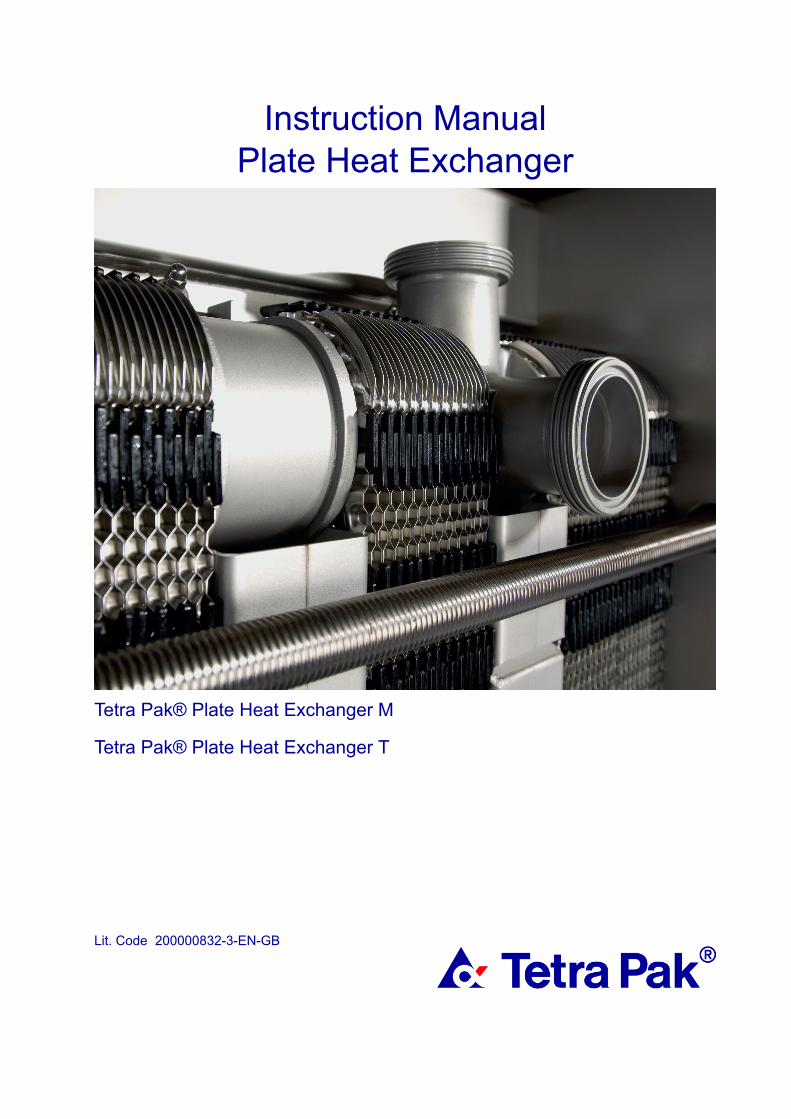
Plate Heat Exchanger
Tetra Pak® Plate Heat Exchanger M
Tetra Pak® Plate Heat Exchanger T
Lit. Code 200000832-3-EN-GB
Instruction Manual
Manufactured by Alfa Laval for Tetra PakSupplied and serviced by Tetra Pak
Always contact your local Tetra Pak representative, also where this manual states referencesto Alfa Laval.
How to contact Tetra Pak:
Contact details for all countries are continually updated on our website.
Please visit www.tetrapak.com and contact your local Tetra Pak representative
Published byAlfa Laval Lund ABBox 74Visit: Rudeboksvägen 1226 55 Lund, Sweden+46 46 36 65 00+46 46 30 50 [email protected]
The original instructions are in English
© Alfa Laval Corporate AB 2019-10
This document and its contents are subject to copyrights and other intellectual property rights owned by Alfa Laval Corporate AB. No part of this document may be copied, re-produced ortransmitted in any form or by any means, or for any purpose, without Alfa Laval Corporate AB’s prior express written permission. Information and services provided in this document aremade as a benefit and service to the user, and no representations or warranties are made about the accuracy or suitability of this information and these services for any purpose. All rightsare reserved.

EnglishDownload local language versions of this instructionmanual from www.alfalaval.com/tetrapak-manuals oruse the QR codeбългарскиИзтеглете версиите на това ръководство заупотреба на местния език от www.alfalaval.com/tetrapak-manuals или използвайте QR кода.ČeskýStáhněte si místní jazykovou verzi tohoto návodu kobsluze z www.alfalaval.com/tetrapak-manuals nebopoužijte QR kód.DanskHent lokale sprogversioner af denne brugervejledningpå www.alfalaval.com/tetrapak-manuals eller brug QR-koden.DeutschSie können die landessprachlichen Versionen diesesHandbuch von der Website www.alfalaval.com/tetrapak-manuals oder über den QR-Codeherunterladen.ελληνικάΠραγματοποιήστε λήψη εκδόσεων του παρόντοςεγχειριδίου οδηγιών σε τοπική γλώσσα από τοwww.alfalaval.com/tetrapak-manuals ήχρησιμοποιήστε τον κωδικό QR.EspañolDescárguese la versión de este Manual deinstrucciones en su idioma local desdewww.alfalaval.com/tetrapak-manualso utilice el códigoQR.EestiSelle kasutusjuhendi kohaliku keele versiooni saatealla laadida lingilt www.alfalaval.com/tetrapak-manualsvõi kasutades QR-koodi.SuomalainenLaitaa tämän käyttöohjeen suomenkielinen versioosoitteesta www.alfalaval.com/tetrapak-manuals taiQR-koodilla.FrançaisTéléchargez des versions de ce manuel d’instructionsen différentes langues sur www.alfalaval.com/tetrapak-manuals ou utilisez le code QR.HrvatskiPreuzmite lokalne verzije jezika ovog korisničkogpriručnika na poveznici www.alfalaval.com/tetrapak-manuals ili upotrijebite QR kod.
MagyarAz Ön nyelvére lefordított használati útmutatótletöltheti a www.alfalaval.com/tetrapak-manualsweboldalról, vagy használja a QR-kódot.ItalianoScarica la versione in lingua locale del manuale diistruzioni da www.alfalaval.com/tetrapak-manualsoppure utilizza il codice QR.日本の
www.alfalaval.com/tetrapak-manuals からご自分の言語の取扱説明書 をダウンロードするか、QR コードをお使いください。
한국의
www.alfalaval.com/tetrapak-manuals 에서 이 사용 설명서의 해당 언어 버전을 다운로드하거나 QR 코드를사용하십시오.LietuvosLejupielādējiet šīs rokasgrāmatas lokālo valoduversijas no vietnes www.alfalaval.com/tetrapak-manuals vai izmantojiet QR kodu.LatvijasAtsisiųskite šios instrukcijos versijas vietos kalba išwww.alfalaval.com/tetrapak-manuals arbapasinaudokite QR kodu.NederlandsDownload de lokale taalversies van deinstructiehandleiding vanaf www.alfalaval.com/tetrapak-manuals of gebruik de QR-code.NorskLast ned denne instruksjonshåndboken på lokalt språkfra www.alfalaval.com/tetrapak-manuals eller bruk QR-koden.PolskiPobierz lokalne wersje językowe tej instrukcji obsługi zwww.alfalaval.com/tetrapak-manuals lub użyj koduQR.PortuguêsDescarregue as versões locais na sua língua destemanual de instruções a partir de www.alfalaval.com/tetrapak-manuals ou use o código QR.Português do BrasilFaça download das versões deste manual deinstruções no idioma local em www.alfalaval.com/tetrapak-manuals ou use o código QR.RomânescVersiunile în limba locală ale acestui manual deinstrucţiuni pot fi descărcate de pe www.alfalaval.com/tetrapak-manuals sau puteţi utiliza codul QR.
PусскийРуководство пользователя на другом языке выможете загрузить по ссылке www.alfalaval.com/tetrapak-manuals или отсканировав QR-код.SlovenskiPrenesite različice uporabniškega priročnika v svojemjeziku s spletne strani www.alfalaval.com/tetrapak-manuals ali uporabite kodo QR.SlovenskýMiestne jazykové verzie tohto návodu na používanie sistiahnite z www.alfalaval.com/tetrapak-manuals alebopoužite QR kód.SvenskaLadda ned lokala språkversioner av dennabruksanvisning från www.alfalaval.com/tetrapak-manuals eller använd QR-koden.中国
从 www.alfalaval.com/tetrapak-manuals 或使用 QR 书下书此使用书 明书的本地书言版本。
Contents
1 Denomination table................................................................................................. 7
2 Preface............................................................................................................................ 9
2.1 Conditions and Requirements................................................................................... 92.2 Environmental compliance...................................................................................... 10
3 Safety..............................................................................................................................11
3.1 Safety considerations.............................................................................................. 113.2 Definitions of expressions........................................................................................11
4 Description..................................................................................................................13
4.1 Components............................................................................................................ 134.2 Name plate.............................................................................................................. 154.3 Function...................................................................................................................174.4 Multi-section............................................................................................................ 184.5 Multi-pass................................................................................................................ 194.6 Identification of plate side........................................................................................19
5 Installation................................................................................................................... 21
5.1 Before installation....................................................................................................215.2 Requirements.......................................................................................................... 225.3 Lifting.......................................................................................................................245.4 Raising.....................................................................................................................25
6 Operation..................................................................................................................... 27
6.1 Start-up....................................................................................................................276.2 Unit in operation...................................................................................................... 296.3 Shut-down............................................................................................................... 29
7 Maintenance.............................................................................................................. 31
7.1 Cleaning – Product side.......................................................................................... 317.2 Cleaning – Non-product side...................................................................................347.3 Opening...................................................................................................................36
7.3.1 Bolt configuration....................................................................................... 367.3.2 Opening procedure.................................................................................... 37
7.4 Manual cleaning of opened units.............................................................................397.4.1 Deposits removable with water and brush.................................................407.4.2 Deposits not removable with water and brush...........................................40
7.5 Closing.....................................................................................................................417.6 Pressure test after maintenance..............................................................................43
7.7 Regasketing.............................................................................................................447.7.1 Clip-on / ClipGrip........................................................................................45
8 Storage of the heat exchanger......................................................................47
8.1 Storage in packing box............................................................................................478.2 Taken out of service.................................................................................................48
1 Denomination tableTetra Pak® Plate Heat Exchanger M
Tetra Pak® Plate Heat Exchanger T
Manufactured by Alfa Laval for Tetra Pak
Supplied and serviced by Tetra Pak
Alfa Laval model denomination in manual Tetra Pak model denominations
Alfa Laval Base 3
Tetra Pak® Plate Heat Exchanger MS3-SRTetra Pak® Plate Heat Exchanger MS3-KSRTetra Pak® Plate Heat Exchanger MSD3-SRTetra Pak® Plate Heat Exchanger MSD3-KSR
Alfa Laval Base 6
Tetra Pak® Plate Heat Exchanger MN6-SRTetra Pak® Plate Heat Exchanger MN6-KSRTetra Pak® Plate Heat Exchanger MS6-SRTetra Pak® Plate Heat Exchanger MS6-KSRTetra Pak® Plate Heat Exchanger MSD6-SRTetra Pak® Plate Heat Exchanger MSD6-KSR
Alfa Laval Base 10
Tetra Pak® Plate Heat Exchanger MN10-SRTetra Pak® Plate Heat Exchanger MN10-KSRTetra Pak® Plate Heat Exchanger MS10-SRTetra Pak® Plate Heat Exchanger MS10-KSR
Alfa Laval Base 11
Tetra Pak® Plate Heat Exchanger MN11-SRTetra Pak® Plate Heat Exchanger MP11-SRTetra Pak® Plate Heat Exchanger MP11-KSM
Alfa Laval M line 6Tetra Pak® Plate Heat Exchanger MN6-SMTetra Pak® Plate Heat Exchanger MS6-SM
Alfa Laval M line 10Tetra Pak® Plate Heat Exchanger MN10-SMTetra Pak® Plate Heat Exchanger MS10-SM
Alfa Laval M line 15
Tetra Pak® Plate Heat Exchanger MN15-SRTetra Pak® Plate Heat Exchanger MS15-SRTetra Pak® Plate Heat Exchanger MN15-SMTetra Pak® Plate Heat Exchanger MS15-SMTetra Pak® Plate Heat Exchanger MND15-SR
Alfa Laval M line TS6 Tetra Pak® Plate Heat Exchanger T6-SR
200000832-3-EN-GB 7
EN

200000832-3-EN-GB8
1 Denomination tableEN
2 PrefaceThis manual provides information needed to install, operate and carry outmaintenance of your gasketed plate-and-frame heat exchanger.
The following models are covered in this manual:
• Base 3
• Base 6
• Base 10
• Base 11
• M line 6
• M line 10
• M line 15
• M line TS6
2.1 Conditions and Requirements
Prior knowledge
The heat exchanger shall be operated by persons who have studied theinstructions in this manual and have knowledge of the process. This includesknowledge of precautions regarding media type, pressures, temperatures inthe heat exchanger as well as specific precautions required by the process.
Maintenance and installation of the heat exchanger shall be done by personswho have knowledge and authorization according to local regulations. Thismay include actions such as piping, welding and other kind of maintenance.
For maintenance actions not described in this manual, contact your Alfa Lavalrepresentative for advice.
PHE drawings
PHE (plate heat exchanger) drawings mentioned in the manual are thedrawings included in the delivery of the heat exchanger.
Warranty conditions
The warranty conditions are usually included in the signed sales contract priorto the order of the delivered heat exchanger. Alternatively, the warrantyconditions are included in the sales offer documentation or with a reference tothe document specifying the valid conditions. If faults occur during thespecified warranty period, always consult your local Alfa Laval representativefor advice.
Report the date when the heat exchanger was put into operation to the localAlfa Laval representative.
Advice
Always consult your local Alfa Laval representative for advice on:
200000832-3-EN-GB 9
EN
• New plate pack dimensions if you intend to change the number of plates
• Selection of gasket material if operating temperatures and pressures arepermanently changed, or if another medium is to be processed in the heatexchanger
2.2 Environmental complianceAlfa Laval endeavours to perform its own operations as cleanly and efficientlyas possible, and to take environmental aspects into consideration whendeveloping, designing, manufacturing, servicing and marketing its products.
Unpacking
Packing material consists of wood, plastics, cardboard boxes and, in somecases, metal straps.
• Wood and cardboard boxes can be reused, recycled or used for energyrecovery.
• Plastics should be recycled or burnt at a licensed waste incineration plant.
• Metal straps should be sent for material recycling.
Maintenance
• All metal parts should be sent for material recycling.
• Oil and all non-metal wear parts must be taken care of in accordance withlocal regulations.
Scrapping
At end of use, the equipment shall be recycled according to relevant, localregulations. Besides the equipment itself, any hazardous residues from theprocess liquid must be considered and dealt with in a proper manner. When indoubt, or in the absence of local regulations, please contact the local AlfaLaval sales company.
200000832-3-EN-GB10
2 PrefaceEN
3 Safety3.1 Safety considerationsThe heat exchanger shall be used and maintained in accordance with AlfaLaval’s instructions in this manual. Incorrect handling of the heat exchangermay result in serious consequences with injuries to persons and/or propertydamage. Alfa Laval will not accept responsibility for any damage or injuryresulting from not following the instructions in this manual.
Your heat exchanger should be used in accordance with the specifiedconfiguration of material, media types, temperatures and pressure for yourspecific heat exchanger
3.2 Definitions of expressions
WARNING Type of hazard
WARNING indicates a potentially hazardous situation which, if notavoided, could result in death or serious injury.
CAUTION Type of hazard
CAUTION indicates a potentially hazardous situation which, if not avoided,may result in minor or moderate injury.
NOTE
NOTE indicates a potentially hazardous situation which, if not avoided,may result in property damage.
200000832-3-EN-GB 11
EN
Safe
ty

200000832-3-EN-GB12
3 SafetyEN
Safe
ty
4 Description4.1 Components
1
2
6
4
7
5
3
8
Main components
1. Frame plateFixed plate with a various number of portholes for the connection of thepiping system. The carrying and guiding bar are attached to the frameplate.
2. Carrying barCarries the plate pack and the pressure plate
3. Plate pack
Heat is transferred from one media to the other through the plates. Theplate pack consists of channel plates, end plates, gaskets and in somecases transition plates. The measurement of the plate pack is the Adimension, i.e the measurement between frame plate and pressure plate.Refer to the PHE drawing.
4. Pressure plate
Moveable plate that can contain a various number of portholes for theconnection of the piping system.
5. Guiding bar
Keeps the channel plates, connection plates and the pressure platealigned at their lower end
6. Support column
Supports carrying and guiding bars.
7. Tightening boltsCompress the plate pack between the frame plate and the pressure plate.Remaining bolts are used as locking bolts.
8. Sanitary connections
Pipes with sanitary fittings or flanges allow the media to enter into or exitfrom the heat exchanger.
200000832-3-EN-GB 13
EN
Multi-section and multi-pass
• Connection plate
Plate used to separate two or more services in one heat exchanger. Theplate pack performing such a service is called a section.
• Corners
The connection plates can be configured by selecting different cornerconnections such as single, double, pass-through or blind.
• Partition plates
Solid stainless steel plates used in multi-pass configurations. Supports theunholed ports of a turning plate.
• Section
When using connection plates, the heat exchanger will contain severalsections (plate packs).
Optional components
• Foot
Adjustable feet.
• Protection sheets
Cover the plate pack and protect against leakage of hot or aggressive fluidsand the hot plate pack.
• Bolt protection
Plastic or stainless steel tubes that protect the threads of the tighteningbolts.
200000832-3-EN-GB14
4 DescriptionEN
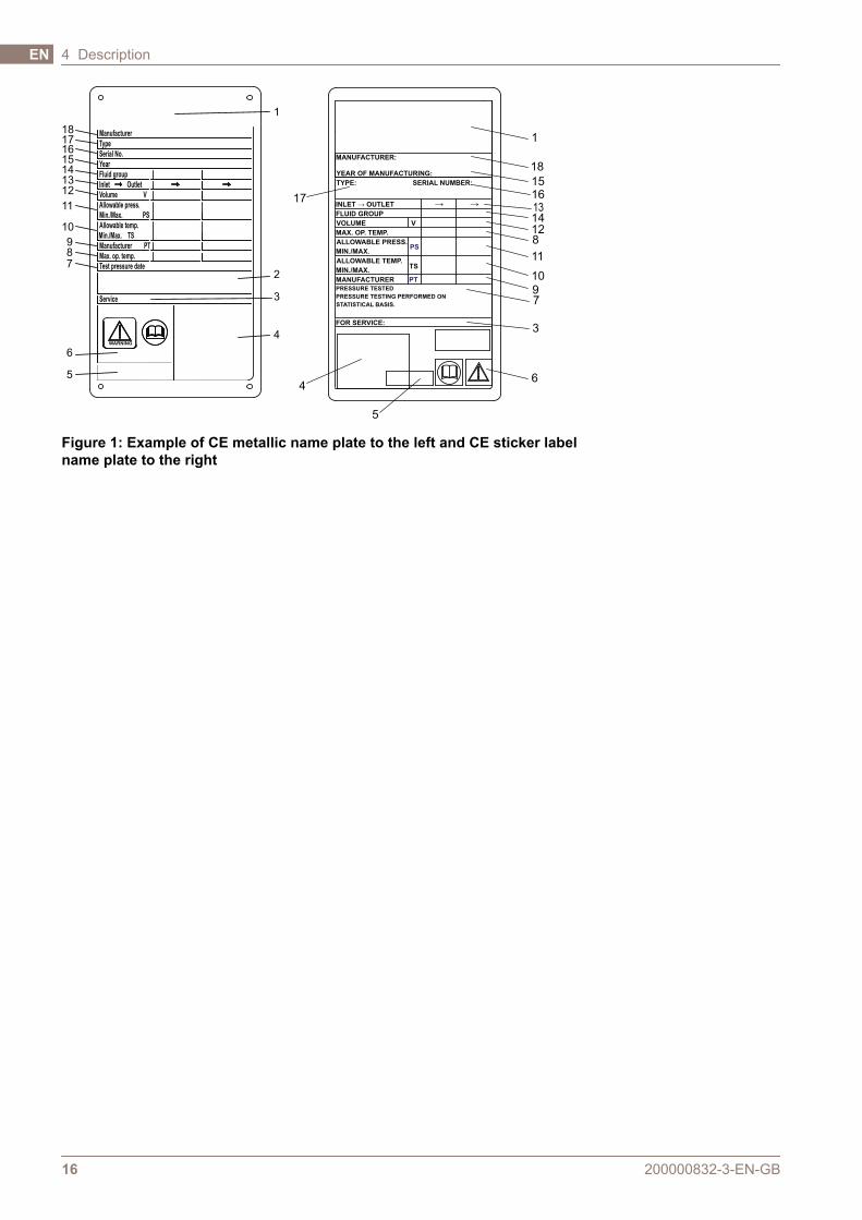
4.2 Name plateThe type of unit, manufacturing number and manufacturing year can be foundon the name plate. Pressure vessel details in accordance with the applicablepressure vessel code are also given. The name plate is fixed to the frameplate, most commonly, or the pressure plate. The name plate can be a steelplate or a sticker label.
WARNING
The design pressures and temperatures for each unit are marked on thename plate. These must not be exceeded.
CAUTION
Avoid aggressive chemicals for cleaning the heat exchanger when asticker label is used.
The design pressure (11) and the design temperature (10), as given on thename plate, are the values against which the heat exchanger is approvedaccording to the pressure vessel code in question. The design temperature(10) may exceed the maximum operating temperature (8) for which thegaskets have been selected for. If the operating temperatures as specified onthe PHE drawing are to be changed the supplier should be consulted.
1. Space for logotype
2. Open space
3. Website for service
4. Drawing of possible locations of connections/Location of 3A tag for 3Aunits
5. Space for mark of approval
6. Warning, read manual
7. Date of pressure test
8. Maximum operating temperature
9. Manufacturer test pressure (PT)
10. Allowable temperatures Min/Max (TS)
11. Allowable pressures Min/Max (PS)
12. Decisive volume or volume for each fluid (V)
13. Locations of the connections for each fluid
14. Decisive fluid group
15. Year of manufacture
16. Serial number
17. Type
18. Manufacturer’s name
200000832-3-EN-GB 15
Description 4 EN
1
2
3
4
18
1716
15
14
13
12
11
10
9
8
7
6
5
1
18
15
1314
128
11
10
9
6
5
4
17
7
3
TS
V
INLET → OUTLET
VOLUME
MIN./MAX.
ALLOWABLE PRESS.
→ →
STATISTICAL BASIS.
MANUFACTURER
FOR SERVICE:
PRESSURE TESTING PERFORMED ON
PRESSURE TESTED
MAX. OP. TEMP.
FLUID GROUP
YEAR OF MANUFACTURING:
MANUFACTURER:
ALLOWABLE TEMP.
MIN./MAX.
TYPE: SERIAL NUMBER:
PT
PS
Service
Year
Manufacturer
Fluid group
Inlet Outlet
Allowable press.
Allowable temp.
Volume V
Manufacturer
Serial No.
Type
Max. op. temp.
Test pressure date
WARNING
Min./Max. PS
Min./Max. TS
PT
16
Figure 1: Example of CE metallic name plate to the left and CE sticker labelname plate to the right
200000832-3-EN-GB16
4 DescriptionEN
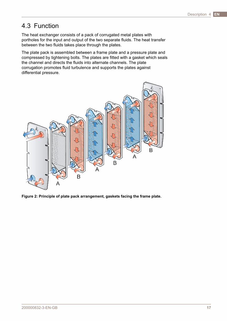
4.3 FunctionThe heat exchanger consists of a pack of corrugated metal plates withportholes for the input and output of the two separate fluids. The heat transferbetween the two fluids takes place through the plates.
The plate pack is assembled between a frame plate and a pressure plate andcompressed by tightening bolts. The plates are fitted with a gasket which sealsthe channel and directs the fluids into alternate channels. The platecorrugation promotes fluid turbulence and supports the plates againstdifferential pressure.
Figure 2: Principle of plate pack arrangement, gaskets facing the frame plate.
200000832-3-EN-GB 17
Description 4 EN
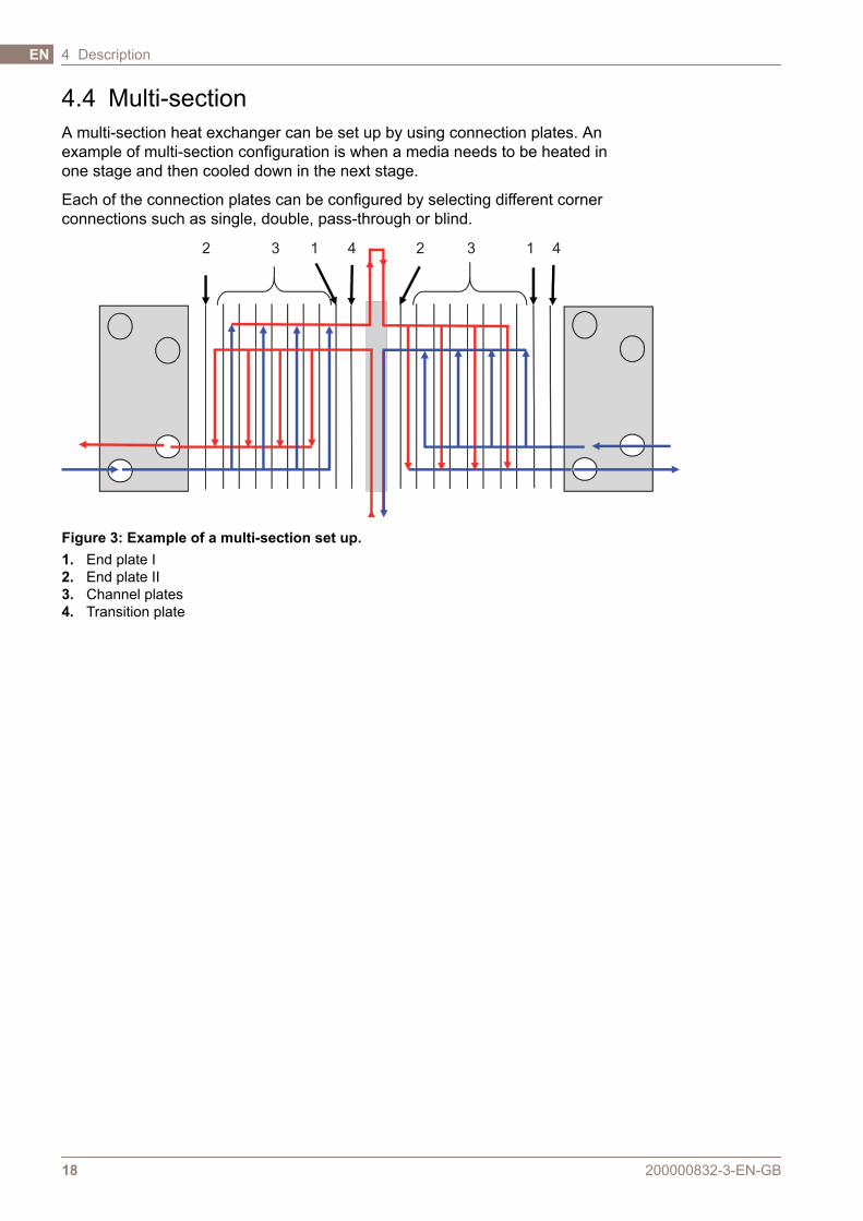
4.4 Multi-sectionA multi-section heat exchanger can be set up by using connection plates. Anexample of multi-section configuration is when a media needs to be heated inone stage and then cooled down in the next stage.
Each of the connection plates can be configured by selecting different cornerconnections such as single, double, pass-through or blind.
1 12 23 34 4
Figure 3: Example of a multi-section set up.1. End plate I2. End plate II3. Channel plates4. Transition plate
200000832-3-EN-GB18
4 DescriptionEN
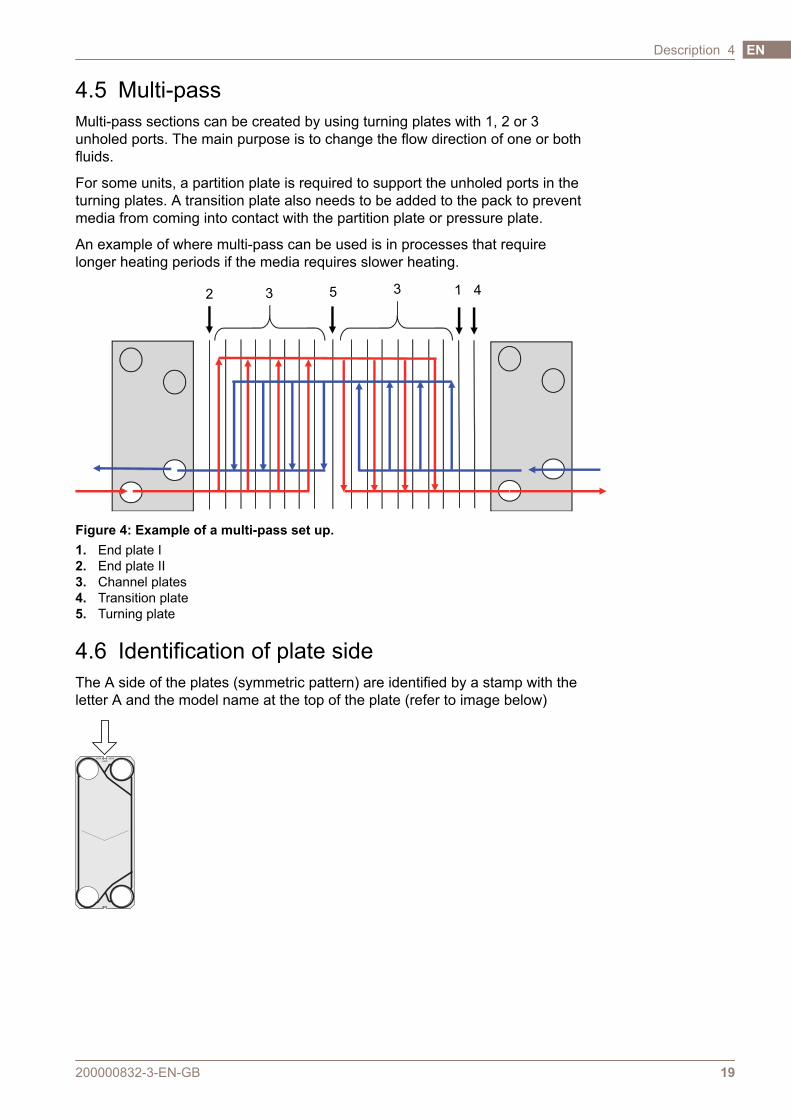
4.5 Multi-passMulti-pass sections can be created by using turning plates with 1, 2 or 3unholed ports. The main purpose is to change the flow direction of one or bothfluids.
For some units, a partition plate is required to support the unholed ports in theturning plates. A transition plate also needs to be added to the pack to preventmedia from coming into contact with the partition plate or pressure plate.
An example of where multi-pass can be used is in processes that requirelonger heating periods if the media requires slower heating.
3 3 12 45
Figure 4: Example of a multi-pass set up.1. End plate I2. End plate II3. Channel plates4. Transition plate5. Turning plate
4.6 Identification of plate sideThe A side of the plates (symmetric pattern) are identified by a stamp with theletter A and the model name at the top of the plate (refer to image below)
AXXX
AXXX AXXX
200000832-3-EN-GB 19
Description 4 EN

200000832-3-EN-GB20
4 DescriptionEN

5 Installation5.1 Before installation
CAUTION
During installation or maintenance, precautions must be taken to avoiddamaging the heat exchanger and its components. Damage tocomponents can adversely affect the performance or serviceability of theheat exchanger.
To consider before installation
• Before connecting any piping, make sure all foreign objects have beenflushed out of the piping system that should be connected to the heatexchanger.
• Before start-up, check that all the tightening bolts are firmly tightened andthat the plate pack has the correct measurements. Refer to the PHEdrawing.
• When connecting the piping system, make sure the pipes do not subjectthe heat exchanger to stress or strain.
• To avoid water hammer, do not use fast-closing valves.
• In automated installations, the stopping and starting of pumps andactuation of valves should be programmed so that the resulting amplitudeand frequency of the pressure variation will be as low as possible.
• If pressure variance is expected, install efficient dampers.
• Make sure that no air remains inside the heat exchanger.
• Safety valves shall be installed according to current pressure vesselregulations.
• It is recommended that protection sheets are used to cover the plate pack.Protect against the leakage of hot or aggressive fluids and the hot platepack.
• Design pressures and temperatures for each model are marked on thename plate. These shall not be exceeded.
200000832-3-EN-GB 21
EN
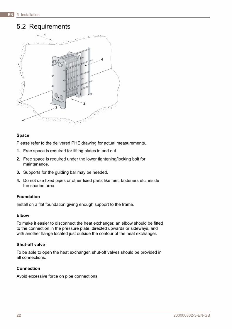
5.2 Requirements
4
1
3
2
Space
Please refer to the delivered PHE drawing for actual measurements.
1. Free space is required for lifting plates in and out.
2. Free space is required under the lower tightening/locking bolt formaintenance.
3. Supports for the guiding bar may be needed.
4. Do not use fixed pipes or other fixed parts like feet, fasteners etc. insidethe shaded area.
Foundation
Install on a flat foundation giving enough support to the frame.
Elbow
To make it easier to disconnect the heat exchanger, an elbow should be fittedto the connection in the pressure plate, directed upwards or sideways, andwith another flange located just outside the contour of the heat exchanger.
Shut-off valve
To be able to open the heat exchanger, shut-off valves should be provided inall connections.
Connection
Avoid excessive force on pipe connections.
200000832-3-EN-GB22
5 InstallationEN

CAUTION
Turning of the connections will damage the gaskets on the end plate andcause leakage.
Fit the pipes so that no tension is transferred to the heat exhanger. Nozzleloads are not permitted.
Pipes connected to the pressure plate and to the connection plates must allow±1% of the distance from the connection to the frame plate (see the assemblyPHE drawing).
Connections in the pressure plate
It is important that the plate pack has been tightened to the correct dimensionA (check against the PHE drawing) before the piping system is connected.
NOTE
Dismantle pipes from the pressure plate and the connections plate(s) sothat the pressure plate and the connection plate(s) are free to move alongthe carrying bar.
Applicable for 3A standards
Once the unit is in position and the feet have been properly adjusted, it is theresponsibility of the end user to seal around the feet with silicone or caulkingto fulfil 3A standard.
200000832-3-EN-GB 23
Installation 5 EN
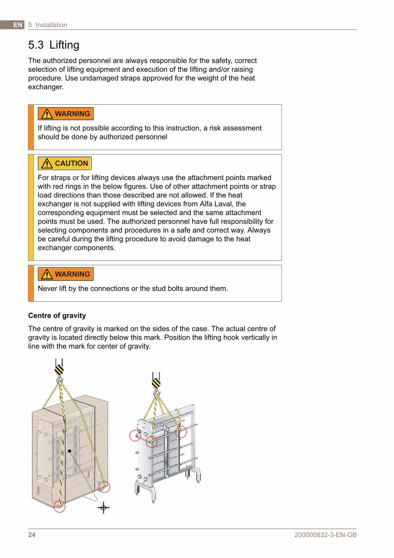
5.3 LiftingThe authorized personnel are always responsible for the safety, correctselection of lifting equipment and execution of the lifting and/or raisingprocedure. Use undamaged straps approved for the weight of the heatexchanger.
WARNING
If lifting is not possible according to this instruction, a risk assessmentshould be done by authorized personnel
CAUTION
For straps or for lifting devices always use the attachment points markedwith red rings in the below figures. Use of other attachment points or strapload directions than those described are not allowed. If the heatexchanger is not supplied with lifting devices from Alfa Laval, thecorresponding equipment must be selected and the same attachmentpoints must be used. The authorized personnel have full responsibility forselecting components and procedures in a safe and correct way. Alwaysbe careful during the lifting procedure to avoid damage to the heatexchanger components.
WARNING
Never lift by the connections or the stud bolts around them.
Centre of gravity
The centre of gravity is marked on the sides of the case. The actual centre ofgravity is located directly below this mark. Position the lifting hook vertically inline with the mark for center of gravity.
200000832-3-EN-GB24
5 InstallationEN
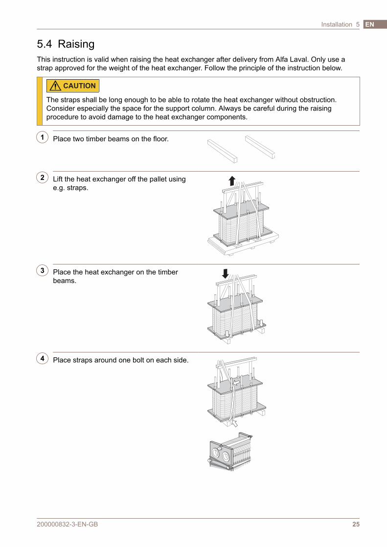
5.4 RaisingThis instruction is valid when raising the heat exchanger after delivery from Alfa Laval. Only use astrap approved for the weight of the heat exchanger. Follow the principle of the instruction below.
CAUTION
The straps shall be long enough to be able to rotate the heat exchanger without obstruction.Consider especially the space for the support column. Always be careful during the raisingprocedure to avoid damage to the heat exchanger components.
1 Place two timber beams on the floor.
2 Lift the heat exchanger off the pallet usinge.g. straps.
3 Place the heat exchanger on the timberbeams.
4 Place straps around one bolt on each side.
200000832-3-EN-GB 25
Installation 5 EN
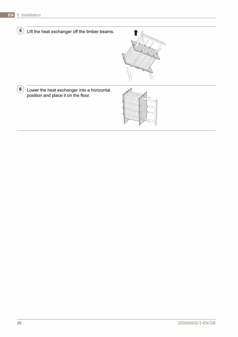
5 Lift the heat exchanger off the timber beams.
6 Lower the heat exchanger into a horizontalposition and place it on the floor.
200000832-3-EN-GB26
5 InstallationEN
6 Operation6.1 Start-upDuring the start-up, check that there are no visible leakages from the plate pack, valves or pipingsystem.
CAUTION
Before pressurizing the heat exchanger, it is important to ensure that the temperature of the heatexchanger is within the temperature range as stated on the name plate.
CAUTION
If the temperature of the heat exchanger is below the minimum temperature for the gaskets priorto the service, it is recommended to heat the heat exchanger above this limit to avoid coldleakage.
NOTE
If several pumps are included in the system, make sure you know which one should be activatedfirst.
Centrifugal pumps must be started with valves closed and the valves must be operated as smoothlyas possible.
Do not run pumps temporarily empty on the suction side.
NOTE
Adjustments of flow rates should be made slowly in order to avoid the risk of pressure surge(water hammer).
Water hammer is a short lasting pressure peak that can appear during the start-up or shut-downof a system, causing liquids to travel along a pipe as a wave at the speed of sound. This cancause considerable damage to the equipment.
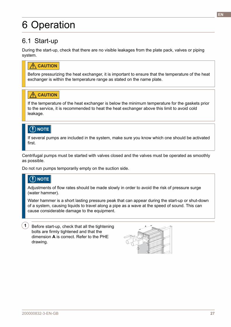
1 Before start-up, check that all the tighteningbolts are firmly tightened and that thedimension A is correct. Refer to the PHEdrawing.
A
200000832-3-EN-GB 27
EN
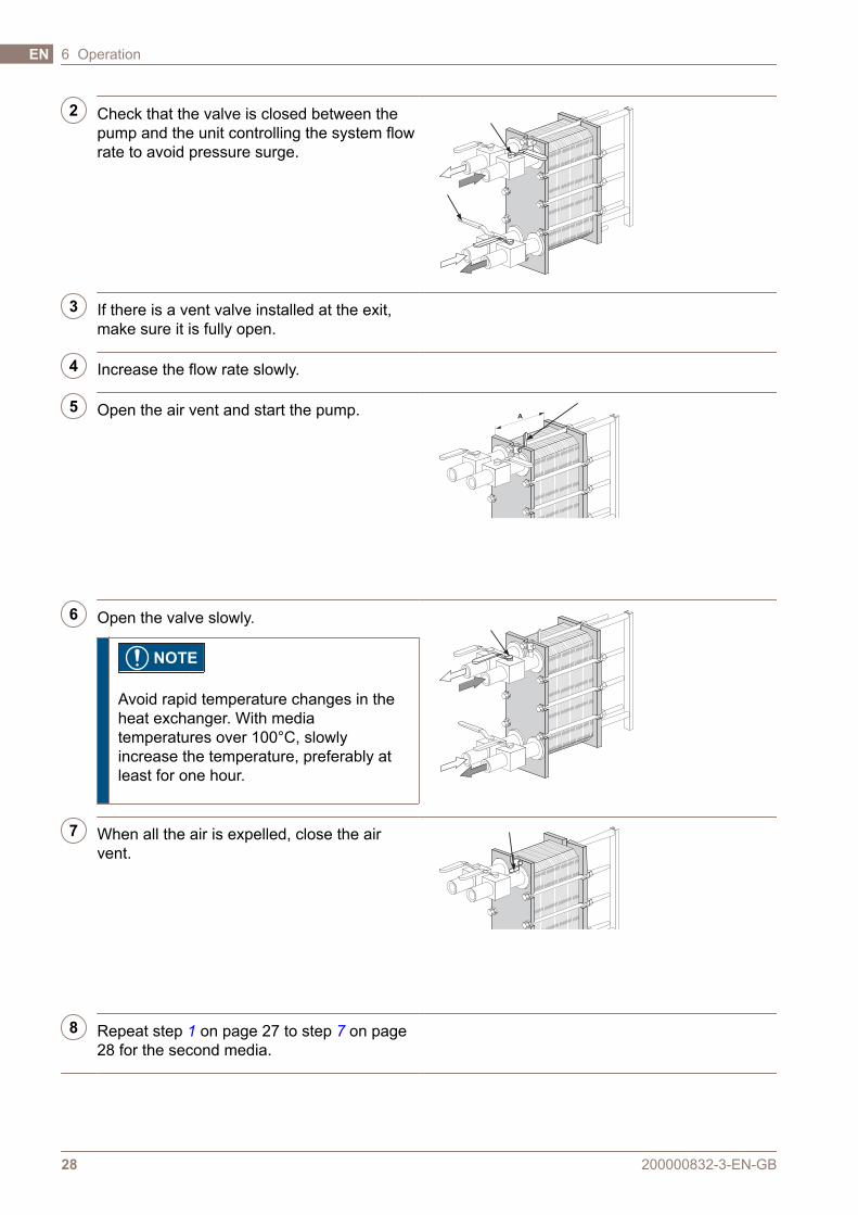
2 Check that the valve is closed between thepump and the unit controlling the system flowrate to avoid pressure surge.
3 If there is a vent valve installed at the exit,make sure it is fully open.
4 Increase the flow rate slowly.
5 Open the air vent and start the pump.A
6 Open the valve slowly.
NOTE
Avoid rapid temperature changes in theheat exchanger. With mediatemperatures over 100°C, slowlyincrease the temperature, preferably atleast for one hour.
7 When all the air is expelled, close the airvent.
8 Repeat step 1 on page 27 to step 7 on page28 for the second media.
200000832-3-EN-GB28
6 OperationEN
6.2 Unit in operationAdjustments of flow rates should be made slowly in order to protect thesystem against sudden and extreme variations of temperature and pressure.
During operation, check that media temperatures and pressures are within thelimits stated on the name plate and the PHE drawing.
WARNING
In case of failures that endanger safety operation, turn off the flows to theheat exchanger in order to decrease the pressure.
6.3 Shut-down
NOTE
If several pumps are included in the system, make sure you know which one should be stoppedfirst.
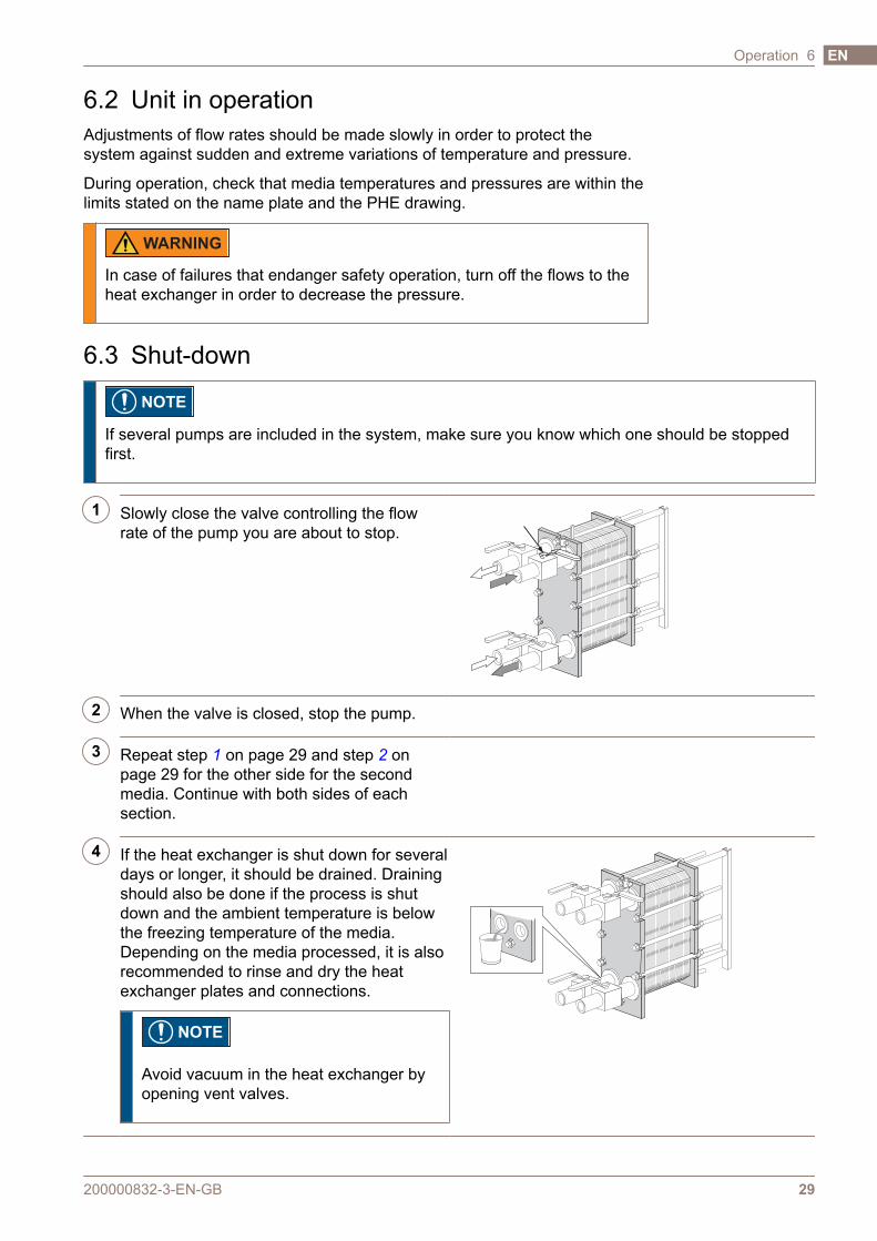
1 Slowly close the valve controlling the flowrate of the pump you are about to stop.
2 When the valve is closed, stop the pump.
3 Repeat step 1 on page 29 and step 2 onpage 29 for the other side for the secondmedia. Continue with both sides of eachsection.
4 If the heat exchanger is shut down for severaldays or longer, it should be drained. Drainingshould also be done if the process is shutdown and the ambient temperature is belowthe freezing temperature of the media.Depending on the media processed, it is alsorecommended to rinse and dry the heatexchanger plates and connections.
NOTE
Avoid vacuum in the heat exchanger byopening vent valves.
200000832-3-EN-GB 29
Operation 6 EN

200000832-3-EN-GB30
6 OperationEN
7 MaintenanceTo keep the heat exchanger in good condition, regular maintenance isrequired. It is recommended to record all maintenance of the heat exchanger.
The plates need to be cleaned on a regular basis. The frequency depends onseveral factors such as type of media and temperature.
Different methods can be used for cleaning (refer to Cleaning – Product sideon page 31 and Cleaning – Non-product side on page 34) or reconditioningcan be performed at an Alfa Laval service center.
After a long period of use, it can be required to regasket the heat exchanger.Refer to Regasketing on page 44.
Other maintenance that should be performed regulary:
• Keep carrying bar and guiding bar clean with paraffin oil.
• Keep the tightening bolts cleaned.
• The stainless steel surfaces of the frame plate, the pressure plate andconnection plates are glass blasted. Clean with a cloth wetted by paraffinoil. Do not degrease the surface!
• Lubricate the threads of the tightening bolts with an EP (extreme pressure)grease. For example, use Gleitmo 800 or its equivalent.
• Grease the suspension wheels on the pressure plate and the connectionplates.
7.1 Cleaning – Product sideImmediately after a production cycle, the product side is normally cleanedthrough the circulation of acid and/or lye as a built-in sequence in theproduction cycle.
NOTE
After the first test run of the product, the heat exchanger should becleaned following a cleaning program applicable to the product inquestion. The heat exchanger should then be opened, refer to Opening onpage 36, and the plate surfaces carefully inspected. The cleaning resultsshould be checked at regular intervals.
WARNING
Use proper protective equipment, such as safety boots, safety gloves andeye protection, when using the cleaning agents.
200000832-3-EN-GB 31
EN
WARNING
Corrosive cleaning liquids. Can cause serious injuries to skin and eyes!
Sterilisation is performed immediately before starting the next productioncycle. Refer to Sterilisation on page 32
Flow rates
The flow rate during the cleaning of the product side should always be at leastthe same as the production’s flow rate. An increased flow rate may be requiredin some cases, e.g. in milk sterilisation and the processing of viscous liquids orliquids containing particles.
Recommended limits for cleaning solutions:
• 5% by volume AlfaCaus at max. 70°C
• 0.5% by weight acid solution at max. 70°C
For detailed information regarding cleaning and sterilisation contact an AlfaLaval representative.
Sterilisation
The methods of sterilisation below are recommendations. Instructions forsterilisation can also be included in the documentation of the complete systemdelivered with the heat exchanger as one part.
Method Instructions
By heatCirculate water of 90°C until all parts of the systemhave been kept at the required temperature for atleast ten minutes.
Chemically by hypochlorite
Before introducing the hypochlorite solution, makesure that the equipment is clean, has cooled downand is free from deposits and that no acid residuesare left.
Gradually add 100 cm3 of hypochlorite solution,containing max. 150 g/l of active chlorine to 100 l ofcirculating water at a max. temperature of 20°C.
Treat for five minutes, up to maximum of 15minutes. Rinse well after sterilisation.
Typical cleaning programs
Consult your local Alfa Laval representative for advice on suitable cleaningprogrammes.
Table 1: Coolers
Products rich in protein
Daily Weekly
Rinsing 5 min Rinsing 5 min
Lye 20 min Acid 15 min
200000832-3-EN-GB32
7 MaintenanceEN

Products rich in protein
Daily Weekly
Rinsing 10 min Rinsing 5 min
Stop Lye 20 min
Sterilisation 10 min Rinsing 10 min
Stop
Sterilisation
Table 2: Pasteurisers and other heaters
Products rich in protein
Daily
Rinsing 5 min
Acid 15 min
Rinsing 5 min
Lye 20 min
Rinsing 5 min 1
Acid 15 min 1
Rinsing 10 min
Stop
1 The need for an additional acid cycle in order to removecalcium carbonate scaling depends on the product. Inmany cases, it is possible to carry out cleaning atconsiderably longer intervals. Sometimes, it is possible toeliminate acid cleaning altogether.
Table 3: High content of insoluble components, e.g. nectar and tomato juice
Products poor in protein
Daily Weekly
Rinsing 10 min Rinsing 10 min
Lye 30 min Lye 30 min
Rinsing 10 min Rinsing 5 min
Stop Acid 15 min
Sterilisation 10 min Rinsing 10 min
Stop
Sterilisation 10 min
Table 4: Low content of insoluble components, e.g. beer and wine
Products poor in protein
Daily 1 Weekly
Rinsing 5 min Rinsing 5 min
Lye 15 min Lye 15 min
Rinsing 10 min Rinsing 5 min
Stop Acid 15 min
1 In some cases, where the risk of growth ofmicroorganisms is low, it is possible to eliminate dailycleaning and replace it with the following procedure:Rinsing 20 min – Stop – Sterilisation 20 min.
200000832-3-EN-GB 33
Maintenance 7 EN

Products poor in protein
Daily 1 Weekly
Sterilisation 10 min Rinsing 10 min
Stop
Sterilisation 10 min
1 In some cases, where the risk of growth ofmicroorganisms is low, it is possible to eliminate dailycleaning and replace it with the following procedure:Rinsing 20 min – Stop – Sterilisation 20 min.
Applicable for 3A standards
When used in a processing system to be sterilised, the system shall beprovided with an automatic shutdown if the product pressure becomes lessthan that of the atmosphere and not be restarted without resterilisation (seeparagraph D10.3). The information plate will then state that the heatexchanger “is” designed for steam sterilisation.
7.2 Cleaning – Non-product sideThe cleaning-in-place (CIP) equipment permits cleaning of the heat exchangerwithout opening it. The purpose of cleaning with CIP is as follows:
• Cleaning of fouling and descaling of lime deposits
• Passivation of cleaned surfaces to reduce susceptibility to corrosion
• Neutralization of cleaning liquids before draining
Follow the instructions of the CIP equipment.
WARNING
Use proper protective equipment, such as safety boots, safety gloves andeye protection, when using the cleaning agents.
WARNING
Corrosive cleaning liquids. Can cause serious injuries to skin and eyes!
CIP equipment
Contact an Alfa Laval sales representative for the size of CIP equipment.
200000832-3-EN-GB34
7 MaintenanceEN
WARNING
The residuals after a cleaning procedure shall be handled according tolocal environmental regulations. After neutralization most cleaningsolutions may be drained into the waste water system under the conditionthat the fouling deposits do not contain heavy metals or other toxic orenvironmentally dangerous compounds. Prior to disposal, it isrecommended to analyze the neutralized chemicals for any hazardouscompounds that were removed from the system.
Cleaning liquidsLiquid Description
AlfaCaus A strong alkaline liquid, for removing paint, fat, oil and biological deposits.
AlfaPhos An acid cleaning liquid for removing metallic oxides, rust, lime and other inorganicscale. Contains repassivation inhibitor
AlfaNeutra A strong alkaline liquid for neutralization of AlfaPhos before drainage.
Alfa P-Neutra For neutralization of Alfa P-Scale.
Alfa P-Scale An acidic powder cleaner for the removal of primary carbonate scale but also otherinorganic scale.
AlfaDescalent A non-hazardous acidic cleaning agent for the removal of inorganic scale.
AlfaDegreaser A non-hazardous cleaning agent for the removal of oil, grease or wax deposits. Alsoprevents foaming when using Alpacon Descaler.
AlfaAdd
AlfaAdd is a neutral cleaning strengthener designed to be used with AlfaPhos,AlfaCaus and Alfa P-Scale. 0.5–1 vol% is added to the total diluted cleaningsolution to provide better cleaning results on oily and fatty surfaces and wherebiological growth occurs. AlfaAdd also reduces any foaming.
If CIP cannot be done, cleaning must be done manually. Refer to Manualcleaning of opened units on page 39.
Chlorine as a growth inhibitor
Chlorine, commonly used as a growth inhibitor in cooling water systems,reduces the corrosion resistance of stainless steels (including high alloys likeAlloy 254).
Chlorine weakens the protection layer of these steels making them moresusceptible to corrosion attacks then they otherwise would be. It is a matter oftime of exposure and concentration.
In all cases where the chlorination of non-titanium equipment cannot beavoided, your local representative must be consulted.
Water of more than 330 ppm Cl ions may not be used in the preparation ofcleaning solutions.
200000832-3-EN-GB 35
Maintenance 7 EN
CAUTION
Ensure that the handling of residuals after using chlorines follow localenvionmental regulations.
NOTE
Titanium is not affected by chlorine.
7.3 OpeningDuring manual cleaning, it is necessary to open the heat exchanger to cleanthe plates.
NOTE
Before opening the heat exchanger, check the warranty conditions. If inany doubt, contact the Alfa Laval sales representative. Refer to Warrantyconditions on page 9.
WARNING
If the heat exchanger is hot, wait until it has cooled down to about 40°C(104°F).
WARNING
If necessary, use proper protective equipment, such as safety boots,safety gloves and eye protection, depending on the type of media in theheat exchanger.
7.3.1 Bolt configurationThe bolt configuration of the heat exchanger varies between different models.The major force of the plate pack is held by the tightening bolts (TB). Todistribute the force evenly over the frame plate and pressure plate, lockingbolts (LB) are used as well. The locking bolts can be shorter and can havesmaller dimensions. In the opening and closing procedure, it is important toidentify the tightening bolts (TB) and the locking bolts (LB). Refer to the picturebelow.
200000832-3-EN-GB36
7 MaintenanceEN
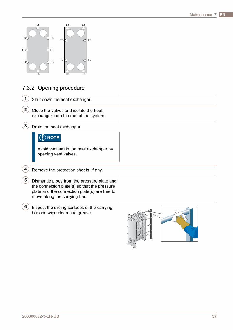
TB TB
TB TB
TB TB
TB TB
LB
LB
LB
LB
LB
LB
LB LB
7.3.2 Opening procedure
1 Shut down the heat exchanger.
2 Close the valves and isolate the heatexchanger from the rest of the system.
3 Drain the heat exchanger.
NOTE
Avoid vacuum in the heat exchanger byopening vent valves.
4 Remove the protection sheets, if any.
5 Dismantle pipes from the pressure plate andthe connection plate(s) so that the pressureplate and the connection plate(s) are free tomove along the carrying bar.
6 Inspect the sliding surfaces of the carryingbar and wipe clean and grease.
200000832-3-EN-GB 37
Maintenance 7 EN
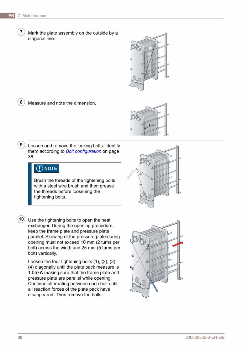
7 Mark the plate assembly on the outside by adiagonal line.
8 Measure and note the dimension.
A
9 Loosen and remove the locking bolts. Identifythem according to Bolt configuration on page36.
NOTE
Brush the threads of the tightening boltswith a steel wire brush and then greasethe threads before loosening thetightening bolts.
10 Use the tightening bolts to open the heatexchanger. During the opening procedure,keep the frame plate and pressure plateparallel. Skewing of the pressure plate duringopening must not exceed 10 mm (2 turns perbolt) across the width and 25 mm (5 turns perbolt) vertically.
Loosen the four tightening bolts (1), (2), (3),(4) diagonally until the plate pack measure is1.05×A making sure that the frame plate andpressure plate are parallel while opening.Continue alternating between each bolt untilall reaction forces of the plate pack havedisappeared. Then remove the bolts.
1
4
3
2
200000832-3-EN-GB38
7 MaintenanceEN
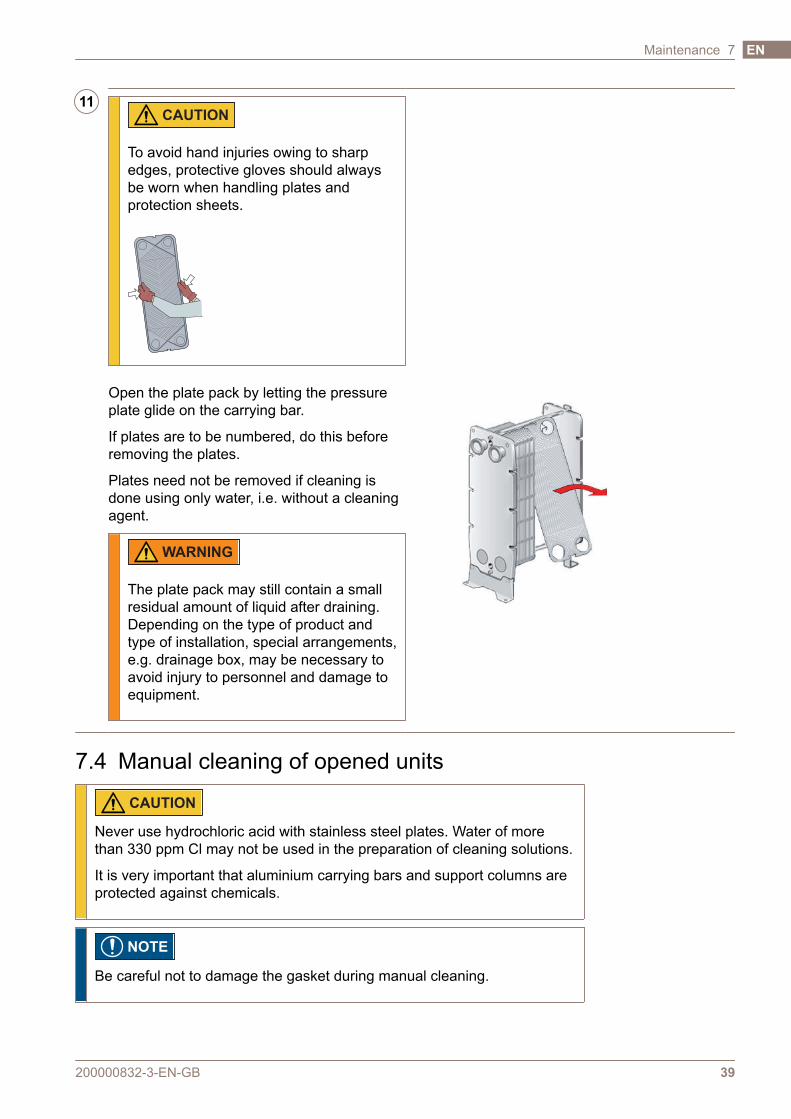
11 CAUTION
To avoid hand injuries owing to sharpedges, protective gloves should alwaysbe worn when handling plates andprotection sheets.
Open the plate pack by letting the pressureplate glide on the carrying bar.
If plates are to be numbered, do this beforeremoving the plates.
Plates need not be removed if cleaning isdone using only water, i.e. without a cleaningagent.
WARNING
The plate pack may still contain a smallresidual amount of liquid after draining.Depending on the type of product andtype of installation, special arrangements,e.g. drainage box, may be necessary toavoid injury to personnel and damage toequipment.
7.4 Manual cleaning of opened units
CAUTION
Never use hydrochloric acid with stainless steel plates. Water of morethan 330 ppm Cl may not be used in the preparation of cleaning solutions.
It is very important that aluminium carrying bars and support columns areprotected against chemicals.
NOTE
Be careful not to damage the gasket during manual cleaning.
200000832-3-EN-GB 39
Maintenance 7 EN
WARNING
Use proper protective equipment, such as safety boots, safety gloves andeye protection, when using the cleaning agents.
WARNING
Corrosive cleaning liquids. Can cause serious injuries to skin and eyes!
7.4.1 Deposits removable with water and brushPlates do not need to be removed from the heat exchanger during cleaning.
WARNING
If necessary, use proper protective equipment. Consider risks such as loose particles and the kindof media that has been used in the heat exchanger.
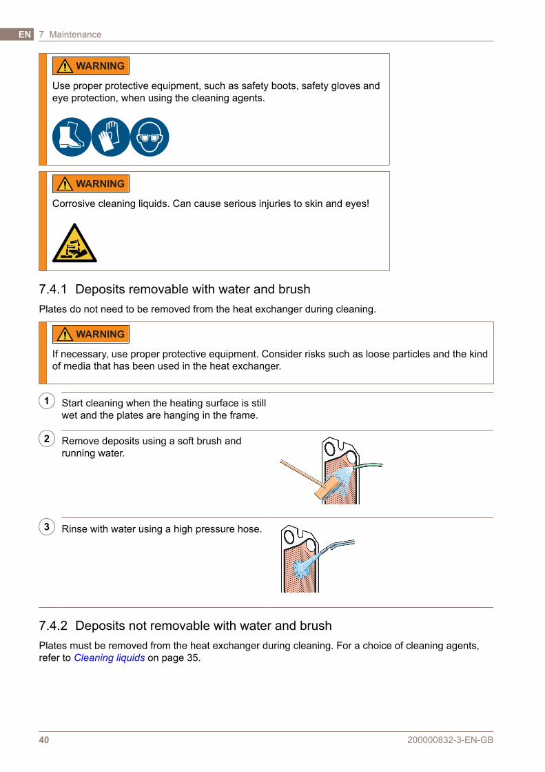
1 Start cleaning when the heating surface is stillwet and the plates are hanging in the frame.
2 Remove deposits using a soft brush andrunning water.
3 Rinse with water using a high pressure hose.
7.4.2 Deposits not removable with water and brushPlates must be removed from the heat exchanger during cleaning. For a choice of cleaning agents,refer to Cleaning liquids on page 35.
200000832-3-EN-GB40
7 MaintenanceEN
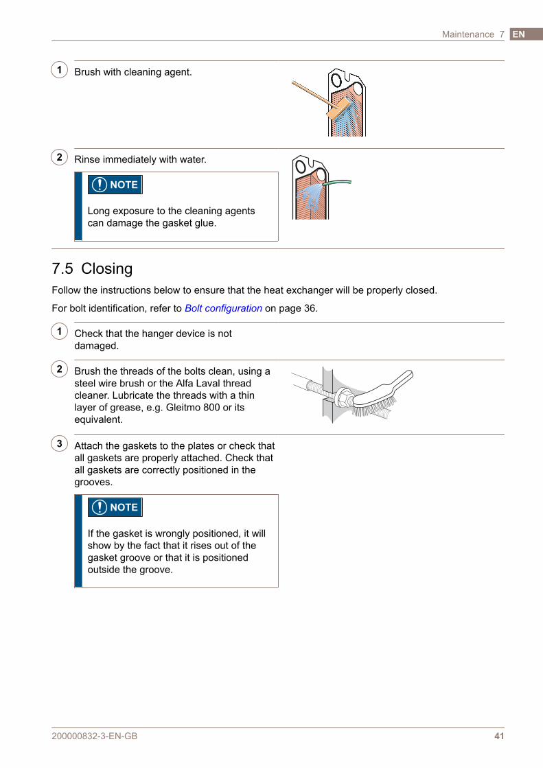
1 Brush with cleaning agent.
2 Rinse immediately with water.
NOTE
Long exposure to the cleaning agentscan damage the gasket glue.
7.5 ClosingFollow the instructions below to ensure that the heat exchanger will be properly closed.
For bolt identification, refer to Bolt configuration on page 36.
1 Check that the hanger device is notdamaged.
2 Brush the threads of the bolts clean, using asteel wire brush or the Alfa Laval threadcleaner. Lubricate the threads with a thinlayer of grease, e.g. Gleitmo 800 or itsequivalent.
3 Attach the gaskets to the plates or check thatall gaskets are properly attached. Check thatall gaskets are correctly positioned in thegrooves.
NOTE
If the gasket is wrongly positioned, it willshow by the fact that it rises out of thegasket groove or that it is positionedoutside the groove.
200000832-3-EN-GB 41
Maintenance 7 EN

4 If the plates have been removed, insert themin alternate directions and with the gasketsturned towards the frame plate or pressureplate as specified on the plate hanging list.Use the marked line that was made when theheat exchanger was opened, refer to step 7on page 38 in Opening on page 36.
5 If the plate pack has been marked on theoutside, check this (see step 7 on page 38 in Opening on page 36). If the plates arecorrectly assembled (A/B/A/B etc.), the edgesform a “honeycomb” pattern, see picture.
6 Press the plate pack together. Position thefour tightening bolts according to thefigure.Tighten the four bolts (1), (2), (3), (4)until the plate pack measure is 1.10×Amaking sure the frame plate and pressureplate are parallel when closing.
1
4
3
2
200000832-3-EN-GB42
7 MaintenanceEN
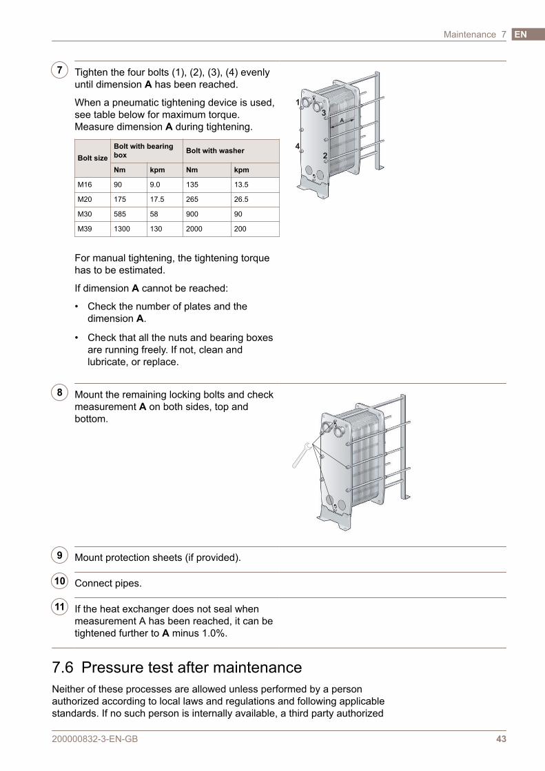
7 Tighten the four bolts (1), (2), (3), (4) evenlyuntil dimension A has been reached.
When a pneumatic tightening device is used,see table below for maximum torque.Measure dimension A during tightening.
Bolt sizeBolt with bearingbox Bolt with washer
Nm kpm Nm kpm
M16 90 9.0 135 13.5
M20 175 17.5 265 26.5
M30 585 58 900 90
M39 1300 130 2000 200
For manual tightening, the tightening torquehas to be estimated.
If dimension A cannot be reached:
• Check the number of plates and thedimension A.
• Check that all the nuts and bearing boxesare running freely. If not, clean andlubricate, or replace.
A
3
1
4
2
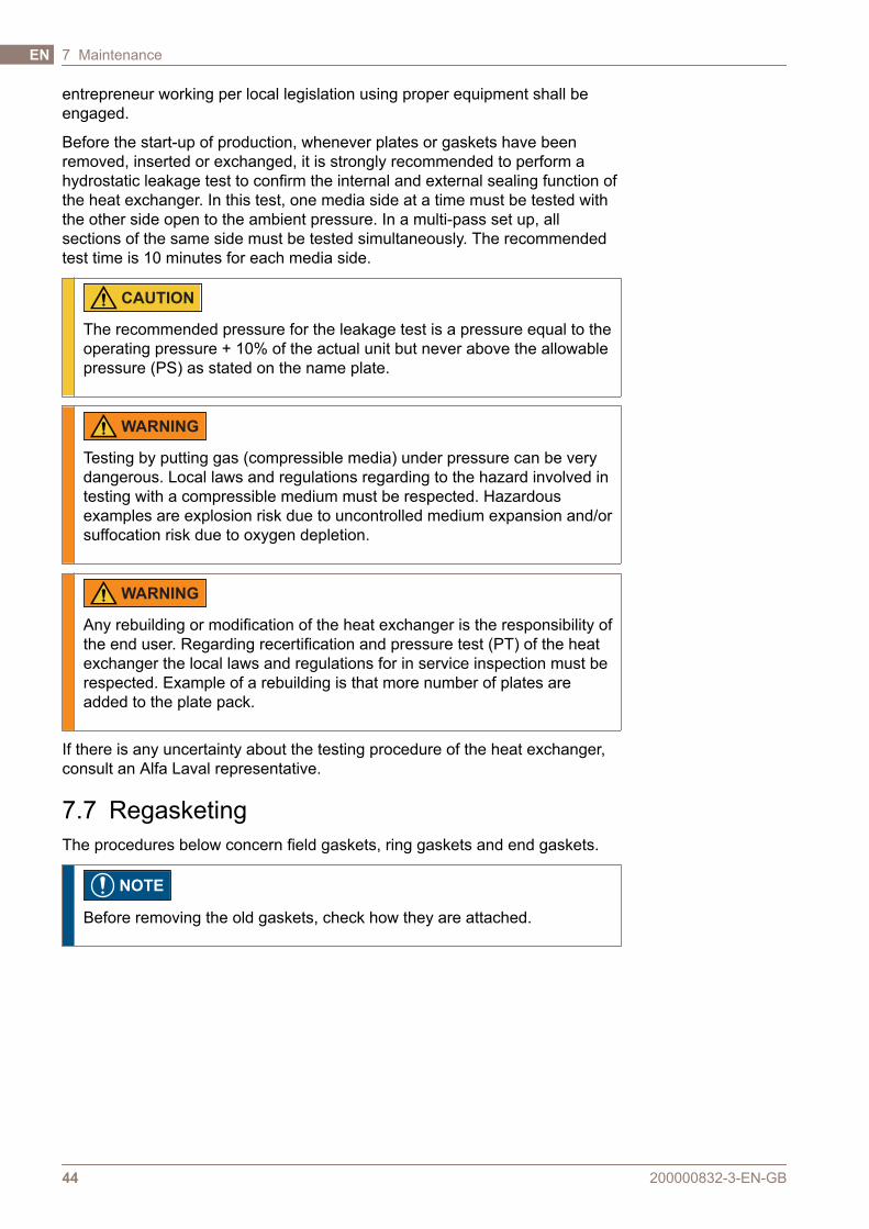
8 Mount the remaining locking bolts and checkmeasurement A on both sides, top andbottom.
9 Mount protection sheets (if provided).
10 Connect pipes.
11 If the heat exchanger does not seal whenmeasurement A has been reached, it can betightened further to A minus 1.0%.
7.6 Pressure test after maintenanceNeither of these processes are allowed unless performed by a personauthorized according to local laws and regulations and following applicablestandards. If no such person is internally available, a third party authorized
200000832-3-EN-GB 43
Maintenance 7 EN
entrepreneur working per local legislation using proper equipment shall beengaged.
Before the start-up of production, whenever plates or gaskets have beenremoved, inserted or exchanged, it is strongly recommended to perform ahydrostatic leakage test to confirm the internal and external sealing function ofthe heat exchanger. In this test, one media side at a time must be tested withthe other side open to the ambient pressure. In a multi-pass set up, allsections of the same side must be tested simultaneously. The recommendedtest time is 10 minutes for each media side.
CAUTION
The recommended pressure for the leakage test is a pressure equal to theoperating pressure + 10% of the actual unit but never above the allowablepressure (PS) as stated on the name plate.
WARNING
Testing by putting gas (compressible media) under pressure can be verydangerous. Local laws and regulations regarding to the hazard involved intesting with a compressible medium must be respected. Hazardousexamples are explosion risk due to uncontrolled medium expansion and/orsuffocation risk due to oxygen depletion.
WARNING
Any rebuilding or modification of the heat exchanger is the responsibility ofthe end user. Regarding recertification and pressure test (PT) of the heatexchanger the local laws and regulations for in service inspection must berespected. Example of a rebuilding is that more number of plates areadded to the plate pack.
If there is any uncertainty about the testing procedure of the heat exchanger,consult an Alfa Laval representative.
7.7 RegasketingThe procedures below concern field gaskets, ring gaskets and end gaskets.
NOTE
Before removing the old gaskets, check how they are attached.
200000832-3-EN-GB44
7 MaintenanceEN
7.7.1 Clip-on / ClipGrip
1 Open the heat exchanger, refer to Openingon page 36.
NOTE
Before opening the heat exchanger,check the warranty conditions. If in anydoubt, contact the Alfa Laval salesrepresentative. Refer to Warrantyconditions on page 9.
2 Remove the old gasket with the plate stillhanging in the frame.
3 Make sure that all sealing surfaces are dry,clean and free of foreign matter such as fat,grease or similar.
4 Check the gasket and remove rubber residualbefore attaching it.
NOTE
Especially the end plate gasket!
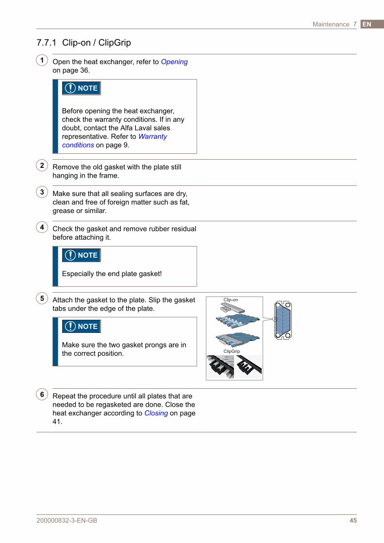
5 Attach the gasket to the plate. Slip the gaskettabs under the edge of the plate.
NOTE
Make sure the two gasket prongs are inthe correct position.
Clip-on
ClipGrip
6 Repeat the procedure until all plates that areneeded to be regasketed are done. Close theheat exchanger according to Closing on page41.
200000832-3-EN-GB 45
Maintenance 7 EN

200000832-3-EN-GB46
7 MaintenanceEN
8 Storage of the heat exchangerAlfa Laval delivers the heat exchanger ready to be put into service uponarrival, if nothing else has been agreed. Nevertheless, keep the heatexchanger in the packing box until installation.
If storing for longer periods of time, such as one month or longer, certainprecautions should be made to avoid unnecessary damage to the heatexchanger. Refer to Outdoor storage on page 47 and Indoor storage on page47.
NOTE
Alfa Laval and its representatives reserve the right to inspect the storagespace and/or equipment whenever necessary until the expiration of thewarranty period stipulated in the contract. Notification must be given 10days prior to the date of inspection.
If there is any uncertainty about the storage of the heat exchanger, consult anAlfa Laval representative.
8.1 Storage in packing boxIf storage of the heat exchanger after delivery is known in advance, inform AlfaLaval when ordering the heat exchanger to ensure that it will be properlyprepared for storage before packing.
Indoor storage
• Store inside a room with the temperature between 15 and 20°C (60–70°F)and humidity up to 70%. For outdoor storage read Outdoor storage on page47.
• To prevent damage to the gaskets, there should not be any ozone-producing equipment in the room such as electric motors or weldingequipment.
• To prevent damage to the gaskets, do not store organic solvents or acids inthe room and avoid direct sunlight, intensive heat radiation or ultravioletradiation.
• The tightening bolts should be well covered with a thin layer of grease.Refer to Closing on page 41.
Outdoor storage
If you need to store your heat exchanger outdoors, follow all the precautions in Indoor storage on page 47 as well as the precautions listed below.
The stored heat exchanger shall be visually checked every third month. Whenclosing the packing it shall be restored to original condition. The checkincludes:
200000832-3-EN-GB 47
EN
• Greasing of the tightening bolts
• Metal port covers
• Protection of the plate pack and gaskets
• The packing
8.2 Taken out of serviceIf, for any reason, the heat exchanger is shut down and taken out of servicefor a long period of time, follow the precautions in Indoor storage on page 47.However, before storage the following actions must be done.
• Check the measurement of the plate pack (measure between frame plateand pressure plate, the A dimension).
• Drain both media sides of the heat exchanger.
• Depending on media, the heat exchanger should be rinsed and then dried.
• The connection should be covered if the piping system is not connected.Use a plastic or plywood cover for the connection.
• Cover the plate pack with non-transparent plastic film.
Start-up after long-term out of service
If the heat exchanger has been taken out of service for an extensive period oftime, longer than one year, the risk of leakage when starting up increases. Toavoid this problem it is recommended to let the gasket rubber rest to regainmost of its elasticity.
1. If the heat exchanger is not in position, follow the instructions in Installationon page 21.
2. Note the measurement between frame plate and pressure plate (Adimension).
3. Remove the feet attached to the pressure plate.
4. Loosen the tightening bolts. Follow the instructions in Opening on page 36.Open the heat exchanger until the plate pack measure is 1.25×A.
5. Leave the heat exchanger for 24–48 hours, the longer the better, forgaskets to relax.
6. Re-tighten according to the instructions in Closing on page 41.
7. Alfa Laval recommends a hydraulic test should be carried out. The media,usually water, should be entered at intervals to avoid sudden shocks to theheat exchanger. It is recommended to test up to the Design Pressure.Refer to the PHE drawing.
200000832-3-EN-GB48
8 Storage of the heat exchangerEN