instruction manual - rc airplanes, multirotors, cars ... · instruction manual fs-l10 ... read this...
TRANSCRIPT

INSTRUCTION MANUAL
FS-l10Digital Proportional Radio Control System
Copyright ©2013-2017 Flysky RC model technology co., ltd

Thank you for purchasing our product, an ideal radio system for beginners or experienced users alike.
Read this manual carefully before operation in order to ensure your safety, and the safety of others or the safe operation of your system.
If you encounter any problem during use, refer to this manual first. If the problem persists, contact your local dealer or visit our service and support website for help: http://www.flysky-cn.com

1. Safety .....................................................1 1.1 Safety Symbols ............................................................1 1.2 Safety Guide ................................................................1
2. Introduction ..........................................3 2.1 System Features ..........................................................3 2.2 Transmitter Overview ...................................................4 2.2.1 Transmitter Antenna ................................................5 2.2.2 Stick/Switche/Knob ................................................5 2.2.3 Status Indicator ........................................................5 2.2.4 Trims ..............................................................................5 2.2.5 SD Card .........................................................................5 2.2.6 Stick Mode ...................................................................6 2.3 Receiver Overview .....................................................7 2.3.1 Receiver Antenna ......................................................7 2.3.2 Status Indicator ..........................................................7 2.3.3 Ports ...............................................................................7
3. Before Use .............................................8 3.1 Transmitter Battery Installation .............................8 3.2 Installing Receiver and servos ................................9
4. Operation Instructions ......................10 4.1 Power On ....................................................................10 4.2 Binding ........................................................................10 4.3 Preflight Inspection ................................................11 4.4 Model Setup ..............................................................11 4.5 Power Off ....................................................................11
5. System Interface.................................12 5.1 Home Screen ............................................................12 5.1.1 Status Bar ...................................................................12 5.1.2 Interface Quick Guide ............................................13 5.2 Interface ...........................................................................13 5.2.1 Bottom Bar Icons .....................................................13 5.3 Built-in Contextual Help ........................................14 5.4 Stick/Knob/Switch Assignment Interface ........14 5.5 Reset Function Interface .......................................14 5.6 Main Menu ................................................................14
6.Function Settings ................................15 6.1 Reverse Function .....................................................15 6.2 End Points Function ................................................15 6.3 Subtrim Function .....................................................15 6.4 Trims ............................................................................16 6.5 Exponentials ..............................................................16 6.6 Aileron to Rudder ....................................................17 6.7 Rudder to Aileron ....................................................17 6.8 Throttle Curve ...........................................................17 6.9 Throttle Delay ...........................................................18
Table of Contents 6.10 Throttle Down ........................................................18 6.11 AUX Channels..........................................................19 6.12 Channel Offset .......................................................19 6.13 Function Delay .......................................................19 6.14 Channel Delay .............................................................19 6.15 Conditions Delay ........................................................20 6.16 Linear Mixes .................................................................20 6.17 Curve Mixes ..................................................................20 6.18 Conditions ....................................................................21 6.19 Logic Switches ........................................................21 6.20 Airplane Structure .................................................22 6.21 Timers ......................................................................23 6.22 Trainer Mode ..........................................................24 6.23 Display Servos ........................................................24 6.24 Spectrum Analyzer ...............................................24 6.25 Models ......................................................................25
7. Airplane / Glider Menu Functions ....27 7.1 Aileron Function ......................................................27 7.2 Flap Function ............................................................27 7.3 Spoiler Function .......................................................27 7.4 Elevator to Flap ........................................................28 7.5 Throttle Needle ........................................................28 7.6 Butterfly ......................................................................28 7.7 Elevator Function .....................................................28 7.8 Rudder Function ......................................................29 7.9 V-tail ............................................................................29
8.Helicopter Menu Functions ...............30 8.1 Throttle Hold .............................................................30 8.2 Throttle Mix ...............................................................30 8.3 Pitch Curve .................................................................30 8.4 Swashplate Mix ........................................................31 8.5 Swashplate Ring .......................................................31 8.6 Hover Adjust .............................................................31 8.7 Gyroscope ..................................................................31 8.8 Governor ....................................................................32 8.9 Helicopter Structure ...............................................32 8.10 Swashplate Type ....................................................32
9.RX Setup ..............................................33 9.1 Bind with a Receiver ...............................................33 9.2 RF Std............................................................................33 9.3 RX PPM Output ........................................................33 9.4 RX Battery Monitor .................................................33 9.5 Low Signal Alarm .....................................................33 9.6 Failsafe ........................................................................34 9.7 Display Sensors ........................................................34 9.8 Choose Sensors ........................................................35 9.9 Set ASL Pressure .......................................................35

9.10 i-BUS Setup .............................................................35 9.11 Servos Frequency ..................................................35 9.12 Range Test ...............................................................36 9.13 Update Receiver ....................................................36
10. System Settings ................................37
10.1 Blacklight Timeout: (Time) .................................37 10.2 Backlight: (%) ..........................................................37 10.3 System Sound .........................................................37 10.4 Alarm Sound ...........................................................37 10.5 Auto Power Off ......................................................37 10.6 Screen Calibration .................................................37 10.7 Units ..........................................................................37 10.8 USB Function ..........................................................37 10.9 Language .................................................................37 10.10 Firmware Update ................................................38 10.11 Factory Reset ........................................................38 10.12 About FS-i10 ...................................................38
11. Product Specification ......................39 11.1 Transmitter Specification (FS-i10) ....................39 11.2 Receiver Specification (FS-iA10B) ....................39 11.3 Sensor Specification .............................................40 11.3.1 RPM Telemetry (Magnetic) Module (FS-
CPD01) ........................................................................40 11.3.2 RPM Telemetry (Optical) Module (FS-
CPD02) .........................................................................40 11.3.3 Temperature Acuquisition Module (FS-
CTM01) ........................................................................40 11.3.4 Voltage Acquisition Module ( FS-CVT01) ....
........................................................................................40 11.3.5 Altitude Acquisition Module (FS-CAT01) ...
......................................................................................40 11.3.6 i-Bus Receiver(FS-CVT01).............................41 11.3.7 i-Bus Receiver (FS-CVT02)............................41 11.3.8 i-Bus Receiver (FS-CVT04)............................41
Appendix 1 FCC Statement ...................42

1
• Do not fly at night or in bad weather like rain or thunderstorm. It can cause erratic operation or loss of control.
• Do not use the product when the visibility is limited.
• Do not use the product on rainy or snowy days. Should any type of moisture (water or snow) enter any component of the system, erratic operation and loss of control may occur.
• Interference could cause loss of control. To ensure the safety of you and others, do not operate in the following places:• Near any site where other radio control activity may occur• Near high voltage power lines or communication broadcasting antennas• Near people or roads• On waterways where passenger boats are present
• Do not store your R/C system in the following places:• In extremely hot or cold environments• Where the system will be exposed to sunlight• Where the humidity is high• Near sources of steam or condensation
• Do not use this product when you are tired, uncomfortable, or under the influence of alcohol or drugs. It may cause serious injury to yourself as well as others.
• Do not leave within reach of small children or animals.
• Never grip the transmitter antenna when operating a model. It significantly degrades the RF signal quality and strength and may cause loss of control.
• Do not touch any part of the model that generates heat during operating or immediately after use, like the engine, motor, or speed control. These parts may be very hot and can cause serious burns.
1. Safety
1.1 Safety Symbols
Pay close attention to the following symbols and their meanings. Failure to follow these warnings could cause damage, injury or death.
1.2 Safety Guide
Warning • Not following these instructions may lead to major injuries.
Danger • Not following these instructions may lead to serious injuries or death.
Attention • Not following these instructions may lead to minor injuries.
Prohibited Mandatory

FS-l10Digital proportional radio control system
2
• Misuse of this product can lead to serious injuries or death. To ensure the safety of you and your equipment, read this manual and follow the instructions.
• Make sure the product is properly installed in your model. Failure to do so may result in serious injury.
• Make sure to disconnect the receiver battery before turning off the transmitter. Failure to do so may lead to unintended operation and cause an accident.
• Ensure that all motors operate in the correct direction. If not, adjust the direction first.
• Make sure the model flies within a certain distance. Otherwise, it would cause loss of control.
• Before powering up the model, make sure that the throttle is at its lowest position.
• The 2.4GHz radio band is completely different from the previously used lower frequency bands. Always keep your model in sight as a large object can block the RF signal and lead to loss of control.
• Note that 2.4GHz systems may affect nearby planes or cars after you turn on the transmitter.
• Set the failsafe function to protect your model.
• Check the model functions before operation.
• Stop operation if any abnormal activity is observed.
• Always store the battery in a cool, dry place.
3
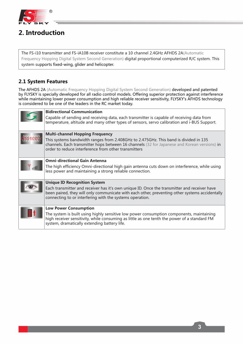
2. Introduction
The FS-i10 transmitter and FS-iA10B receiver constitute a 10 channel 2.4GHz AFHDS 2A(Automatic Frequency Hopping Digital System Second Generation) digital proportional computerized R/C system. This system supports fixed-wing, glider and helicopter.
2.1 System FeaturesThe AFHDS 2A (Automatic Frequency Hopping Digital System Second Generation) developed and patented by FLYSKY is specially developed for all radio control models. Offering superior protection against interference while maintaining lower power consumption and high reliable receiver sensitivity, FLYSKY's AFHDS technology is considered to be one of the leaders in the RC market today.
Bidirectional CommunicationCapable of sending and receiving data, each transmitter is capable of receiving data from temperature, altitude and many other types of sensors, servo calibration and i-BUS Support.
Multi-channel Hopping FrequencyThis systems bandwidth ranges from 2.408GHz to 2.475GHz. This band is divided in 135 channels. Each transmitter hops between 16 channels (32 for Japanese and Korean versions) in order to reduce interference from other transmitters
Omni-directional Gain AntennaThe high efficiency Omni-directional high gain antenna cuts down on interference, while using less power and maintaining a strong reliable connection.
Unique ID Recognition SystemEach transmitter and receiver has it's own unique ID. Once the transmitter and receiver have been paired, they will only communicate with each other, preventing other systems accidentally connecting to or interfering with the systems operation.
Low Power ConsumptionThe system is built using highly sensitive low power consumption components, maintaining high receiver sensitivity, while consuming as little as one tenth the power of a standard FM system, dramatically extending battery life.

FS-l10Digital proportional radio control system
4
2.2 Transmitter Overview
VRA Knob
SWD Switch
SWB Switch
SWA Switch
VRD Knob
SWC Switch
Trim 1
Rudder/Aileron
Throttle/Elevator
Power Button
VRB Knob
VRC Knob
SWE Switch
SWF Switch
SWH Switch
VRE Knob
SWG Switch
Trim 3
Trim 4
Power Button
LCD
Trim 2
Rudder/Aileron
Throttle/Elevator
Trainer Port
Antenna
Handle
USB Port
Stylus
SD Card Slot Battery Compartment Battery Compartment cover
Grip

5
2.2.1 Transmitter Antenna
Note• To ensure high signal quality, the antenna should be perpendicular to the models
fuselage. When adjusting the angle of the antenna, make sure that the antenna does not point directly towards the front or back of the model.
Note • Never grip the transmitter antenna during operation. It significantly degrades signal quality and strength and may cause loss of control.
Note • Do not bend the antenna wire beyond 90 degrees. Bending the antenna further could result in damage to the wire.
2.2.2 Stick/Knob/Switch
The FS-i10 has 2 gimbals, 8 switches and 5 knobs, 3 of which can be locked.
• Sticks: The sticks are used for rudder, elevator, alieron and throttle control. • Switches: The switches can be assigned to various functions for quick access. • Knob/VR: The knobs/VRsc an be assigned to various functions to make quick adjustments during use.
Lockable rotary knob: Press the knob down to lock it into position. To bring the knob back up, press down again and release after which the knob can be rotated normally.
2.2.3 Status Indicator
The status indicator is used to indicate the power and working status of the transmitter.
• Off: the transmitter is powered off. • Blue light: the transmitter is on and working.• Flashing: low voltage alarm.
2.2.4 Trims
There are 4 groups of trim switches affecting surface position. Each time a trim is toggled, the trim will move one step. You can hold the trim in the desired direction to make quicker trim adjustments. When the trim position reaches the middle, the transmitter beeps in a higher tone.
2.2.5 SD Card
This system only supports SD 2.0 with a capacity of 1GB or above.
SupportsModelImportandexport.Refereto【6.25Models】fordetails.
Note • Turn off the transmitter before removing SD card.

FS-l10Digital proportional radio control system
6
Instructions:
1. Open the battery compartment and remove the battery. 2. Remove the grips located on each side of the transmitter. 3. Use a hex screwdriver to remove the 6 screws securing the back cover. 4. Gently open the transmitter cover and remove the connectors attaching the front to the back from the
botherboard. 5. Use a philips screwdriver to remove the 8 screws at each corner of the gimbals.6. Switch the left and right gimbal, rotate 180 degrees, adjust the wire and secure using the 8 screws.7. Carefully insert the connectors back into the motherboard, reclose the transmitter and secure with the
back covers screws. 8. Reattach the grips and install the battery. 9. Turn on the transmitter, enter the main menu and open the [Display servos] function. Check the channels
and trims are responding as expected.
2.2.6 Stick Mode
The system supports 4 stick modes, the default is [Mode 2]. The blue icon indicates the currently selected mode. Enter the main menu, touch the [System] icon and select your prefered mode.
Changing from modes 2/4 to 1/3 will change the throttle position. This will require the user to open the system and switch the stick positions. The gimbals can be switched by following these instructions.
Elevator
Mode
Throttle
Rudder
Aileron
Mode
Elevator Throttle
Rudder
Aileron
Mode
Mode
Throttle Elevator
Rudder
Aileron
Throttle Elevator
Rudder
Aileron

7
2.3 Receiver Overview
Power/Bind Port
To Servos
PPM Output /To Servos
Antenna
Status Indicator
i-BUS Sensor Interface
i-BUS Serial Interface
2.3.1 Receiver Antenna
Attention • Do not pull or tie the antenna or use the antenna as a servo cable.
2.3.3 Ports
Power, Bind, Channel,Serial and PPM output ports for connecting various components to the receiver.
• PPM/CH1:CanbeconnectedtoservoorusedasaPPMoutput.• CH2 ~CH10:Canbeconnectedtoservos,powersupplyorothercompatiblecomponents.• B/VCC: During the binding process a bind cable is connected here. During normal opertaion the power
is applied to this port. • i-Bus Serial Interface: For connecting an i-BUS module, expansion.• i-Bus Sensor Interface: For connecting sensors.
2.3.2 Status Indicator
The status indicator is used to indicate the power and working status of the receiver.
• Off: the power is not connected. • Lit in red: the receiver is on and working.• Flashing quickly: the receiver is binding mode.• Flashing slowly: the bound transmitter is off or signal is lost.
FS-iA10B uses dual 26mm antenna and can receive and send information at the same time.

FS-l10Digital proportional radio control system
8
3. Before Use
Before using the product please follow the guidelines below to install the battery and connect the device.
3.1 Transmitter battery Installation
Danger • Only use specified battery.
Danger • Do not open, disassemble, or attempt to repair the battery.
Danger • Do not crush/puncture the battery, or short the external contacts.
Danger • Do not expose to excessive heat or liquids.
Danger • Do not drop the battery or expose to strong shocks or vibrations.
Danger • Always store the battery in a cool, dry place.
Danger • Do not use the battery if damaged.
To install the transmitters battery, follow these steps:
1. Open the battery compartment.2. Insert fully charged battery into the battery compartment. Make sure that the metal contacts on the
battery and transmitter have a good connection. 3. Replace the battery compartment cover.

9
Battery
3.2 Installing Receiver and Servos
Make sure that you find an appropriate location to mouth the receiver in order to, ensure performance, stability and prevent outside interference.
Note • Do not power on the receiver during the setup process to prevent loss of control.
90° 90°
接收机
(26mm)
接收机 接收机
Installation:
1. Make sure the receiver is mounted away from motors, electonic speed controllers or any device that emmits excessive electrical noise.
2. Keep the receivers antenna away from conductive materials such as carbon or metal. To ensure normal function make sure there is a gap of at least 1cm between the antenna and the conductive material.
3. Ensure that the two antennas are mounted at 90 degrees to each other, as shown below.
Rudder servo
Throttle servo
Elevator servo
Alieron servo
Aux.1
Aux.2
Aux.3
Aux.4
Aux.5
Aux.6
Switch
Receiver Receiver Receiver

FS-l10Digital proportional radio control system
10
4. Operation Instructions
Follow these guidlines to ensure proper use of your system
Follow these steps to power on the system:
1. Check the system and make sure that:• Thebatteryisfullychargedandinstalledproperly.。• The receiver is off and correctly installed.
2. Hold both power buttons on either side of the LCD until it lights up 3. Connect the receiver power supply to the B/VCC port on the receiver.
Note • Use with caution to prevent damage, injuries or death.
Note• As a safety precaution, the system will not power on unless all the switches are in • their highest position and the throttle is at its lowest position.
4.2 Binding
The transmitter and receiver have been pre-bound before delivery.
1. Turn on the transmitter, enter the main menus, swipe from right to left and select [RX Settings]
2. Check the chart below to find out what RF standard your receiver is using. To change enter the [RF std] menu, press yes when prompted and select the corresponding RF protocol from the list.
3. Select [Bind with a receiver] and press [Yes] to enter bind mode.
14
4.1 Power On
4. Connect the bind cable to the B/VCC port of the receiver.
5. Connect the power to any other port. The indicator will start to flash, indicating that the receiver is in bind mode.• For [AFHDS 2A 2-way], once binding is
complete, the transmitter should exit the bind menu automaticlly.
• For other protocols, select the back button to exit the bind menu.
6. Remove the bind and power cable from the receiver. Then connect the power cable to the B/VCC port.
7. Check the servos' operation. If anything does not work as expected, restart this procedure from the beginning.
If you are using another transmitter or receiver, follow the steps below to bind the TX and RX:
RF Standard Receiver TypeAFHDS GR3F,GR3E,R6B,R9B,R6CAFHDS 2 iR4,iR4B,iR6B,iR10AFHDS 2A 1-way A3, A6AFHDS 2A 2-way iA4B,iA6,iA6B,iA10,iA10B,X6
Bind cable
Battery
Receiver
11
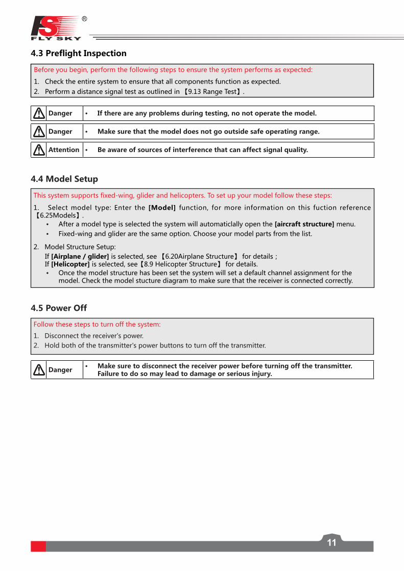
4.3 Preflight Inspection
Before you begin, perform the following steps to ensure the system performs as expected:
1. Check the entire system to ensure that all components function as expected.2.Performadistancesignaltestasoutlinedin【9.13RangeTest】.
Danger • If there are any problems during testing, no not operate the model.
Danger • Make sure that the model does not go outside safe operating range.
Attention • Be aware of sources of interference that can affect signal quality.
This system supports fixed-wing, glider and helicopters. To set up your model follow these steps:
1. Select model type: Enter the [Model] function, for more information on this fuction reference 【6.25Models】.
• After a model type is selected the system will automaticlally open the [aircraft structure] menu.• Fixed-wing and glider are the same option. Choose your model parts from the list.
2. Model Structure Setup: If [Airplane / glider]isselected,see【6.20AirplaneStructure】fordetails; If [Helicopter] isselected,see【8.9HelicopterStructure】fordetails.
• Once the model structure has been set the system will set a default channel assignment for the model. Check the model stucture diagram to make sure that the receiver is connected correctly.
4.4 Model Setup
4.5 Power Off
Danger • Make sure to disconnect the receiver power before turning off the transmitter. Failure to do so may lead to damage or serious injury.
Follow these steps to turn off the system:
1. Disconnect the receiver's power.2. Hold both of the transmitter's power buttons to turn off the transmitter.

FS-l10Digital proportional radio control system
12
5. System Interface
This chapter is an introduction to the menu and menu functions.
5.1 Home Screen
The home screen displays useful information about your model, including sensors and function status etc.
Model NameTransmitter Battery
StatusReceiver Battery
Status
Sensor Output
Model Timer
Engine Timer
Trim 3
Multi Timer 1
Multi Timer 2
Trim 4
SettingsHelp
Trim 2
Airplane/Helicopter Structure
Trim 1
Mute
Throttle Cut Enabled
Trainer Function Enabled
Logic Switches Enabled
Exponential Function Enabled
Flap Function Enabled
Throttle Hold Enabled
Butterfly Function Enabled
Active Condition
5.1.1 Status Bar
Battery Full
Receiver Not Connected
External voltage sensor is chosen, but not connected.
Charged Charging Full Low Battery (Charging Required)
Currently selected model number and name.
Received signal strength. When 5 bars are displayed the signal is at full strength, if the signal displays 2 or less the system will sound an alarm.
Receiver Signal
13
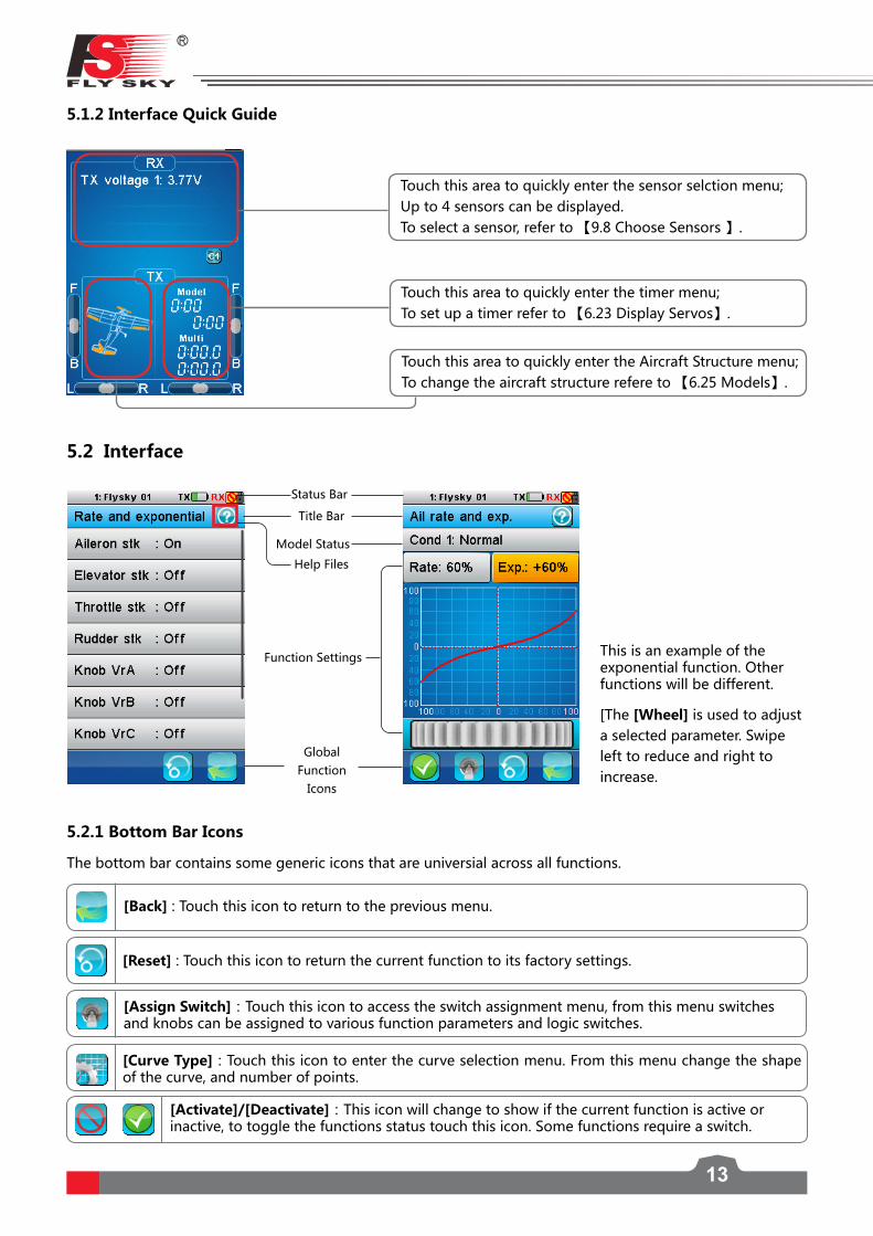
Touch this area to quickly enter the sensor selction menu; Up to 4 sensors can be displayed.Toselectasensor,referto【9.8ChooseSensors】.
Touch this area to quickly enter the timer menu;Tosetupatimerreferto【6.23DisplayServos】.
5.1.2 Interface Quick Guide
Touch this area to quickly enter the Aircraft Structure menu;Tochangetheaircraftstructurerefereto【6.25Models】.
5.2 Interface
Status Bar
Global Function
Icons
Title Bar
Model Status
Function Settings This is an example of the exponential function. Other functions will be different.
Help Files
[The [Wheel] is used to adjust a selected parameter. Swipe left to reduce and right to increase.
The bottom bar contains some generic icons that are universial across all functions.
[Back] : Touch this icon to return to the previous menu.
[Reset] : Touch this icon to return the current function to its factory settings.
[Assign Switch]:Touchthisicontoaccesstheswitchassignmentmenu,fromthismenuswitchesand knobs can be assigned to various function parameters and logic switches.
[Activate]/[Deactivate]:Thisiconwillchangetoshowifthecurrentfunctionisactiveorinactive, to toggle the functions status touch this icon. Some functions require a switch.
5.2.1 Bottom Bar Icons
[Curve Type]:Touchthisicontoenterthecurveselectionmenu.Fromthismenuchangetheshapeof the curve, and number of points.
FS-l10Digital proportional radio control system
14
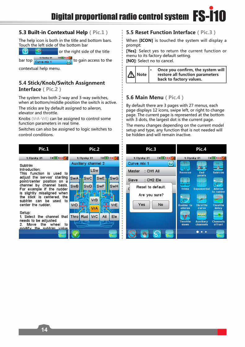
5.3 Built-in Contextual Help(Pic.1) The help icon is both in the title and bottom bars. Touch the left side of the bottom bar
or the right side of the title
bar top to gain access to the
contextual help menu.
5.5 Reset Function Interface(Pic.3) When [ICON] is touched the system will display a prompt:[Yes]: Select yes to return the current function or menu to its factory default setting.[NO]: Select no to cancel.
The system has both 2-way and 3-way switches, when at bottom/middle position the switch is active.The sticks are by default assigned to aileron, elevator and throttle.Knobs (VrA-VrE) can be assigned to control some function parameters in real time. Switches can also be assigned to logic switches to control conditions.
By default there are 3 pages with 27 menus, each page displays 12 icons, swipe left, or right to change page. The current page is represented at the bottom with 3 dots, the largest dot is the current page.The menu changes depending on the current model setup and type, any function that is not needed will be hidden and will remain inactive.
5.4 Stick/Knob/Switch Assignment Interface(Pic.2)
Note• Once you confirm, the system will
restore all function parameters back to factory values.
5.6 Main Menu(Pic.4)
Pic.1 Pic.2 Pic.3 Pic.4

15
6. Function Settings
This section contains the default menu function settings.
The Reverse function is used to correct a servo or motor’s direction in relation to the systems controls. For example, if a servo is mounted upside down in order to fit inside a model.
Endpoints are the limits of the channels’ range of movement. There are two endpoints, one is the low endpoint and one is the high end point.
6.1 Reverse Function (Pic.5)
6.2 End Points Function (Pic.6)
To reverse a channel:This menu contains 10 check boxes, one for each channel, when a channel is reversed the corresponding box will be checked.
• At the top of the current channel, the selected endpoint and percentage are shown.
• The endpoints location is shown as a bar and needle.
• The red needle indicates the current setting for the selected side and channel.
• A real time readout of the channels position can be seen in this menu as a green bar.
2. Select the Up side or Down side as appropriate. 3. Move the wheel at the bottom of the screen
left to reduce the value or right to increase the value.
Pic.5
Pic.6
To set an endpoint:
1. Touch the channel you wish to change. The setup menu for the selected channel displays.
Subtrim changes the center point of the channel. For example, if the ailerons are slightly out of alignment, the subtrim could be used to fix this.
6.3 Subtrim Function (Pic.7)
To set the subtrim function:1. Select the desired channel from the list. The
setup menu for the selected channel displays.• At the top of the current channel, the
selected channel and percentage are shown.
• The center point location is shown as a bar and needle.
• The red needle indicates the current setting for the selected channel.
Pic.7• A real time
readout of the channels position can be seen in this menu as a green bar.
2. Move the wheel at the bottom of the screen left to reduce the value or right to increase the value.
FS-l10Digital proportional radio control system
16
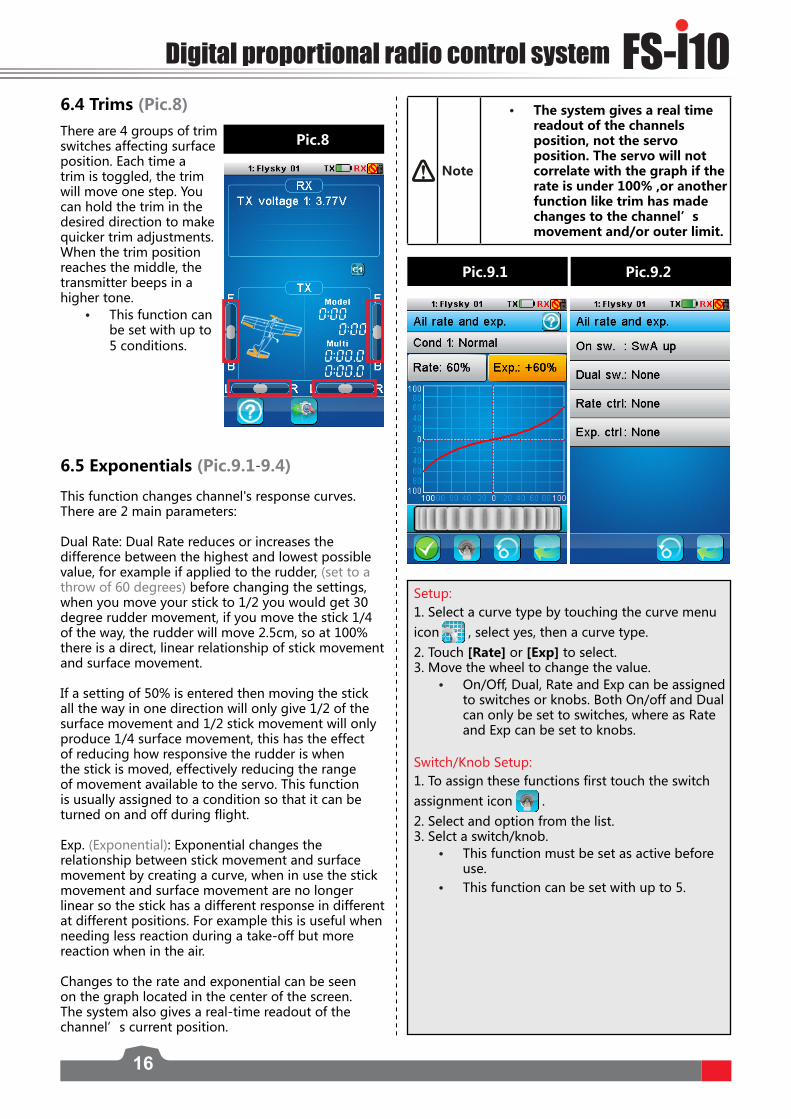
6.4 Trims (Pic.8)There are 4 groups of trim switches affecting surface position. Each time a trim is toggled, the trim will move one step. You can hold the trim in the desired direction to make quicker trim adjustments. When the trim position reaches the middle, the transmitter beeps in a higher tone.
• This function can be set with up to 5 conditions.
6.5 Exponentials (Pic.9.1-9.4)
Pic.8
Pic.9.1 Pic.9.2
This function changes channel's response curves. There are 2 main parameters:
Dual Rate: Dual Rate reduces or increases the difference between the highest and lowest possible value, for example if applied to the rudder, (set to a throw of 60 degrees) before changing the settings, when you move your stick to 1/2 you would get 30 degree rudder movement, if you move the stick 1/4 of the way, the rudder will move 2.5cm, so at 100% there is a direct, linear relationship of stick movement and surface movement.
If a setting of 50% is entered then moving the stick all the way in one direction will only give 1/2 of the surface movement and 1/2 stick movement will only produce 1/4 surface movement, this has the effect of reducing how responsive the rudder is when the stick is moved, effectively reducing the range of movement available to the servo. This function is usually assigned to a condition so that it can be turned on and off during flight. Exp. (Exponential): Exponential changes the relationship between stick movement and surface movement by creating a curve, when in use the stick movement and surface movement are no longer linear so the stick has a different response in different at different positions. For example this is useful when needing less reaction during a take-off but more reaction when in the air.
Changes to the rate and exponential can be seen on the graph located in the center of the screen. The system also gives a real-time readout of the channel’s current position.
Setup:1. Select a curve type by touching the curve menu icon , select yes, then a curve type.2. Touch [Rate] or [Exp] to select.3. Move the wheel to change the value.
• On/Off, Dual, Rate and Exp can be assigned to switches or knobs. Both On/off and Dual can only be set to switches, where as Rate and Exp can be set to knobs.
Switch/Knob Setup: 1. To assign these functions first touch the switch assignment icon .2. Select and option from the list. 3. Selct a switch/knob.
• This function must be set as active before use.
• This function can be set with up to 5.
Note
• The system gives a real time readout of the channels position, not the servo position. The servo will not correlate with the graph if the rate is under 100% ,or another function like trim has made changes to the channel’s movement and/or outer limit.

17
This function enables the user to adjust the ratio between stick and servo movement using a linear line or non-linear curves.
• If the airplane does not have an engine, such as a glider, this icon will not be displayed.
This is useful when wanting to change how the throttle reacts at between different stick positions, for example having a smaller throttle change when the stick is between 0-30%, then a larger throttle change between 30% and 100%. If your models throttle is not linear, it is also possible to use this function to create a more linear movement.
Curve Type
The number of points in the curve is shown below the line graph, L being the lowest point and H being the highest point.
6.6 Aileron to Rudder (Pic.10)The aileron to rudder automatically creates a coordinated turn for the aircraft with aileron and rudder. The pre-programmed mix is 10% by default, meaning that if your aileron has moves to 100% of its range of movement the rudder will move 10%. If the aircraft does not have ailerons or a rudder, these function icon will not be displayed. When this function is activated, a tick will be shown on the bottom left side of the screen, if not press the bottom left icon.
6.7 Rudder to Aileron (Pic.11)This function can be used to counteract undesirable roll of aircraft with rudders and ailerons. The pre-programmed mix is 10% by default, meaning that if your rudder has moves to 100% of its range of movement the aileron will move 10%.
Pic.10
Pic.11
Setup:
1. Activate the function by touching the function on/off icon located at the bottom left of the screen.
2. Touch [High side rate] or [Low side rate] to select.3. Use the wheel to change the value. Repeat as necessary.
• This function must be set as active before use.• This function can be toggled using a switch/button, which is assigned in
the [Keys function] .
• This function can be set with up to 5 conditions.
Setup:
1. Activate the function by touching the function on/off icon located at the bottom left of the screen.
2. Touch [High side rate] or [Low side rate] to select.3. Use the wheel to change the value. Repeat as necessary.
• This function must be set as active before use. • This function can be set with up to 5 conditions.
6.8 Throttle Curve (Pic.12)
FS-l10Digital proportional radio control system
18
This function contains two options, idle up and throttle cut.
• The idle up function is useful for the models with fuel engines to keep the engine idling and prevent an accidental stall (If an engines throttle is cut too far it will cut out, this function is designed to prevent that).
• Throttle cut is used to cut the engine by bringing the throttle down to the 0 position.
• Both these functions must be assigned to a toggle to be activated or deactivated. Once idle up has been assigned to a toggle use the wheel to change the value.
Setup:
1. In order to make changes to this function ensure that switches have been assigned to each idle up and throttle cut.
2. Use the wheel at the bottom of the screen to change the idle down value. The required setting will change from model to model, consult your engines user manual for recommendations.
3. Use the assigned switches to turn idle down and throttle cut on or off. The functions current state is show below the channel position bar. • This function can be set with up to 5
conditions.
6.10 Throttle Down (Pic.14)
Pic.12
Pic.13 Pic.14
Setup:
1. Activate the function by touching the function on/off icon located at the bottom left of the screen.
2. To change the number of points or the curve type press the [Gear Symbol] second from the left at the bottom of the screen and touch the desired option. There are 2 types of curve available, linier and V curve. • Changeing the curve will delete any changes made to the old curve.
3. Select a point by touching it and use the wheel to change the value.
Editing Curves
To edit a curve touch one of the points listed at the bottom of the screen then use the wheel to change its value.
• This function can be set with up to 5 conditions.
Throttle delay is used to reduce the response speed of throttle output and imitate non electrical engine. If the model does not have an engine, such as a glider, this icon will not be displayed. The delay can be set from 0s to 10s, if a delay of 10 seconds is set, it will take 10 seconds for the throttle to catch up with stick movements.
Setup: Move the wheel to set the throttle delay time. The red bar represents throttle stick position and the green bar represents current channel position.
As shown in the picture below: The delay time is 5 seconds. There will be 5 seconds delay when moving throttle stick from bottom side to top side. Due to 5 seconds delay, the throttle is in the position when it is one second and it displays 20%.
6.9 Throttle Delay (Pic.13)

19
Setup:
1. It is possible to rename the AUX channels by selecting name and using the onscreen keyboard.
2. To select the AUX channel controller (Toggle/Stick/Knob), select the control option then select the desired controller from the menu.
6.11 Aux Channels(Pic.15)
The model function allows users to set auxiliary channels. Every channel that is not assigned during the model setup will be set as an AUX channel. AUX channels can be used to control various extra features on an aircraft including landing gear, brakes, lights...
Setup:Select the desired channel to offset and move the wheel to make changes. The position of the corresponding channel is displayed in real time.
6.12 Channel Offset (Pic.16)
This function can be used to correct problems with alignment. For example if a servos range of motion is too great in one direction and not enough in another, it is possible to offset the channel by +/- 50%.
Pic.15
Setup:Select the desired function and move the wheel to change the delay time. The position of the corresponding function output is displayed in real-time represented by the red bar. The green bar represents the stick position.
6.13 Function Delay(Pic.17)
Pic.16
Function delay is used to slow down the response speed of basic function output. It can be adjusted from 0 to 10 seconds. For example if the delay is set to 5 seconds it will take 5 seconds for the function to catch up with the knob or sticks position.
Pic.17
6.14 Channel Delay(Pic.18)
Channel delay is used to slow down the response speed of channel output. It can be adjusted from 0 to 10 seconds. For example if the delay is set to 5 seconds it will take 5 seconds for the channel to catch up with the stick position. The position of the corresponding channel output is displayed in real-time. The red bar represents the stick position and the green bar represents channel output position.
Pic.18

FS-l10Digital proportional radio control system
20
Setup:
1. Select a condition from the list.
2. Use the onscreen wheel to set the value.
Conditions delay adds a delay to response time of a condition. This is used in order to provide more realism in certain models.
Pic.19
Setup:
1. Select the bottom left icon to ensure there is a tick in the box.
2. Select the [master], this channel/input will control the slaves output. It is possible to select stick/knob, basic functions or a channel output.
3. Select a slave, slaves may only be output channels however may also include aux channels.
4. If desired set an offset to the slave channel, this works in the same way as the channel offset function.
6.16 Linear Mixes (Pic.20)
This function is used to create a mix between channels. For example if at low throttle some automated flap movement was desired then it is possible to create a mix to do this. The difference between curve mixes and linear mixes is that it is not possible to create a nonlinear relationship between the master and slave.
Pic.20
Setup:
1. Select the bottom left icon to ensure there is a tick in the box.
6.17 Curve Mixes(Pic.21)
This function is used to create a non-linear mix between channels. For example if at lower throttle some automated flap movement was desired then it is possible to create a mix to do this. The difference between linear mixes and curve mixes is that it is possible to create a nonlinear relationship between the master and slave.
Pic.21
Setup:
1. Select desired channel.2. Move the wheel to modify the delay time.
• This function can be used to emulate movements of real aircraft. For example if a scale model of a real airplane is being used, it is possible to use this function to imitate the reaction time of the real plane.
6.15 Conditions Delay (Pic.19)
5. Select low side and high side to set the limits of movement for the slave channel. For example, if high side is set to 10 percent when the master channel is at 100% the slave will move 1/10th of its full range of motion.
21
Setup:
1. To rename a condition, select a condition between 1 and 5, select name.
2. Use the onscreen keyboard to enter in the new name.
3. To copy a condition, select a condition you wish to copy and select copy, then select the condition you wish to copy to. The system will prompt if you are sure, select [yes] to confirm. • To assign a condition to a switch refere to
【6.19 Logic Switches】.
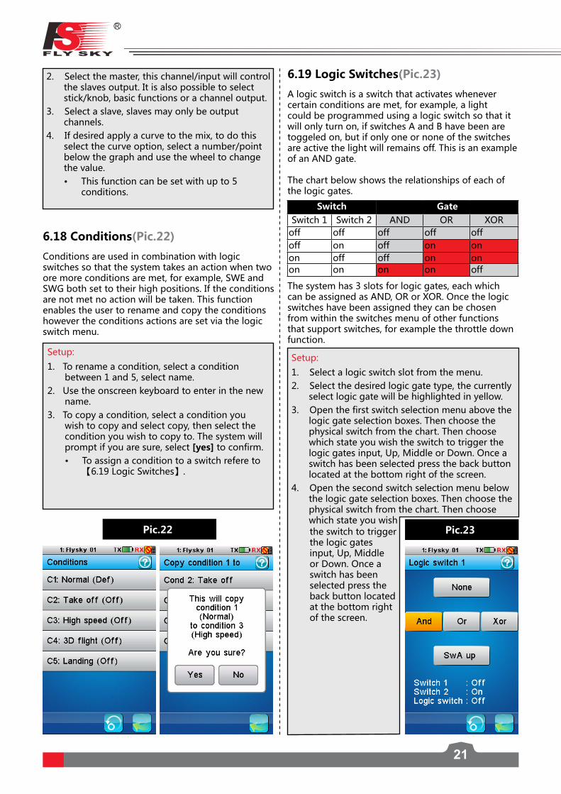
6.18 Conditions(Pic.22)
Conditions are used in combination with logic switches so that the system takes an action when two ore more conditions are met, for example, SWE and SWG both set to their high positions. If the conditions are not met no action will be taken. This function enables the user to rename and copy the conditions however the conditions actions are set via the logic switch menu.
Pic.22
2. Select the master, this channel/input will control the slaves output. It is also possible to select stick/knob, basic functions or a channel output.
3. Select a slave, slaves may only be output channels.
4. If desired apply a curve to the mix, to do this select the curve option, select a number/point below the graph and use the wheel to change the value. • This function can be set with up to 5
conditions.
6.19 Logic Switches(Pic.23)
A logic switch is a switch that activates whenever certain conditions are met, for example, a light could be programmed using a logic switch so that it will only turn on, if switches A and B have been are toggeled on, but if only one or none of the switches are active the light will remains off. This is an example of an AND gate.
The chart below shows the relationships of each of the logic gates.
The system has 3 slots for logic gates, each which can be assigned as AND, OR or XOR. Once the logic switches have been assigned they can be chosen from within the switches menu of other functions that support switches, for example the throttle down function.
Setup:
1. Select a logic switch slot from the menu.2. Select the desired logic gate type, the currently
select logic gate will be highlighted in yellow. 3. Open the first switch selection menu above the
logic gate selection boxes. Then choose the physical switch from the chart. Then choose which state you wish the switch to trigger the logic gates input, Up, Middle or Down. Once a switch has been selected press the back button located at the bottom right of the screen.
4. Open the second switch selection menu below the logic gate selection boxes. Then choose the physical switch from the chart. Then choose which state you wish
Pic.23the switch to trigger the logic gates input, Up, Middle or Down. Once a switch has been selected press the back button located at the bottom right of the screen.
Switch GateSwitch 1 Switch 2 AND OR XOR
off off off off offoff on off on onon off off on onon on on on off
FS-l10Digital proportional radio control system
22
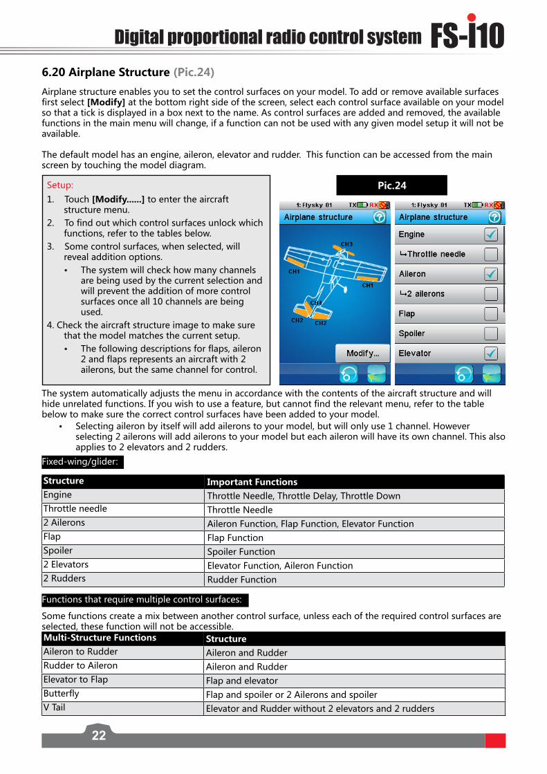
Airplane structure enables you to set the control surfaces on your model. To add or remove available surfaces first select [Modify] at the bottom right side of the screen, select each control surface available on your model so that a tick is displayed in a box next to the name. As control surfaces are added and removed, the available functions in the main menu will change, if a function can not be used with any given model setup it will not be available.
The default model has an engine, aileron, elevator and rudder. This function can be accessed from the main screen by touching the model diagram.
Pic.24Setup:
1. Touch [Modify......] to enter the aircraft structure menu.
2. To find out which control surfaces unlock which functions, refer to the tables below.
3. Some control surfaces, when selected, will reveal addition options.• The system will check how many channels
are being used by the current selection and will prevent the addition of more control surfaces once all 10 channels are being used.
4. Check the aircraft structure image to make sure that the model matches the current setup. • The following descriptions for flaps, aileron
2 and flaps represents an aircraft with 2 ailerons, but the same channel for control.
The system automatically adjusts the menu in accordance with the contents of the aircraft structure and will hide unrelated functions. If you wish to use a feature, but cannot find the relevant menu, refer to the table below to make sure the correct control surfaces have been added to your model.
• Selecting aileron by itself will add ailerons to your model, but will only use 1 channel. However selecting 2 ailerons will add ailerons to your model but each aileron will have its own channel. This also applies to 2 elevators and 2 rudders.
Structure Important FunctionsEngine Throttle Needle, Throttle Delay, Throttle DownThrottle needle Throttle Needle2 Ailerons Aileron Function, Flap Function, Elevator FunctionFlap Flap FunctionSpoiler Spoiler Function2 Elevators Elevator Function, Aileron Function2 Rudders Rudder Function
Multi-Structure Functions Structure Aileron to Rudder Aileron and RudderRudder to Aileron Aileron and RudderElevator to Flap Flap and elevatorButterfly Flap and spoiler or 2 Ailerons and spoilerV Tail Elevator and Rudder without 2 elevators and 2 rudders
6.20 Airplane Structure (Pic.24)
Fixed-wing/glider:
Functions that require multiple control surfaces:
Some functions create a mix between another control surface, unless each of the required control surfaces are selected, these function will not be accessible.

23
Model/Engine Timer:
The engine timer triggers when throttle value exceeds the set value, and stops when back under that value.
These functions are also known as basic functions, as referred to in the [Trainer Mode], [Curve Mixes], [Function Delay] and [Linear mixes] sections of this user manual. Some functions can apply the function of one control surface to another, for example, the aileron function can apply aileron control to flaps and elevators. This can be used to enhance the effect of a control surface in order to make the model more responsive and agile. To see what control surfaces are required for these functions refer to the table below. Basic Functions Airplane StructureAileron function 2 Ailerons 2 Flaps,2 ElevatorsElevator function 2 Ailerons, 2 ElevatorsThrottle Curve EngineRudder Function RudderFlap Function 2 Flaps, 2 AileronsSpoiler Function 2 SpoilersThrottle Needle Throttle NeedlePitch Curve Variable pitchGyroscope Function GyroscopeGovernor Function Governor
6.21 Timers (Pic.25)
This function is usually used to keep track of time to reduce the risk of aircraft running out of battery/fuel and crashing. These are very useful when used in conjunction with a toggle.
Setup:
1. Activate the function by pressing the function on/off icon .
2. To change the timer trigger percentage just move the wheel. • Both timers can be reset by touching [Reset] button.
Multi-purpose timer:
Up timer: starts counting from zero when triggered. Down timer: counts down from a selected time, to select the time you wish to count down from select min/sec/ms and use the wheel to select the time. Down then up timer: start from a selected time and count down, once they reach 0 they go into the negative and effectively start counting up again.
Pic.25
Setup:1. Select a timer type.2. Select start to start the timer and reset to reset.

FS-l10Digital proportional radio control system
24
Setup:
1. Select a channel to assign2. Select [Stick or Knob], [Basic function],
[Channel output] or [None].3. Depending on which selection you make
different options will be available. The next choice will be controlled by the master controller.
4. Activate the function using the on/off icon in the bottom left of the screen. • To give the slave control of the model the
SWE switch must be held down, as soon as SWE is in the up position the master has full control.
Pic.26
This function allows you to connect 2 transmitters together using a dedicated cable connected to the back of the FS-i10. The FS-i10 that enables the trainer function will become the master, and will be able to override the other FS-i10. Usually this function is used by instructors to teach students how to fly, they can give the student full control but can quickly step in if anything goes wrong.
The master can control up to 8 of the slaves channels and can select stick, knob, basic functions (for example aileron function), output channel or none.
6.23 Display Servos(Pic.27)
This function displays the model’s channel output and can be used to test output and servo range.
Pic.27
6.24 Spectrum Analyzer (Pic.28)
6.22 Trainer Mode (Pic.26)
Setup:
Press the icon and the servos will move slowly though their entire range. Press the icon again to toggle the function.
Warning• Make sure the model engine is powered off while
the test function is activated. If powered on, it will rev up and cause unexpected results
The spectral analyzer function is used to monitor other devices that are emitting radio signals and at what frequency. This is useful as it is possible to find out if there is likely to be any interference from other sources such as WIFI. Because it is only useful to know about frequencies that may interfere with the function of the system, this function is limited to 2.4GHz to 2.48GHz.
From bottom to top of this graph is measured in dBm, which is a measurement of the [loudness] or strength

25
Pic.28
of the signal. This is measured from -120dBm to -60dBm. The higher up the graph the signal appears the stronger it is, and has a bigger chance of causing interference.
Along the bottom of the graph is a solid block of red, this in this case is just background noise. Background noise usually isn’t a problem and a level of background noise can be expected everywhere.
Along the graph at different frequencies red spikes can be seen. Each of these spikes is a signal which is almost constant, hence their red color, and most likely is another ADFHS system communicating with a receiver. Each of these red spikes is the result of the transmitter and receiver hopping between different frequencies in an attempt to reduce interference, by moving around different parts of the frequency band. This reduces the risk of losing control due to the signal being masked, or drowned out by another signal that is static.
Function Use
This function uses a buffer that layers information on top of the graph, this enables the system to calculate how often a signal is present, the most often the signal is there the closer to red it will be. This means that the function keeps the information on the graph until the allotted time (in this case 1 min) is up, after that the information will be deleted from the buffer and removed from the graph. So in this case all information gathered over 1 min ago will be deleted automatically and will no longer be represented in the graph.
There are two settings in this function, [Reset] and [Period].
Reset removes all data from the graph starting from scratch. A prompt will appear asking if you wish to continue.
Period… changes the amount of time the buffer holds information before deleting it. For example if the buffer is only 10 seconds long, any information stored 10 seconds ago will be deleted.
6.25 Models (Pic.29.1-29.4)
This function is used to change, reset, rename or copy model setups. The FS-iT4S can store up to 20 different models in the internal memory.
[Select model]: Changes the current model. Touch [Select model] and then choose the name of the model to load it.
[Reset model]: Changes the current model settings to the factory default.
To reset a model:
1. Make sure the current model is the one you want to reset. If not, select the desired model as described above.
2. Select [Reset model] and then [Yes] in the confirmation box. The model will be reset to the factory default.
[Name]: Renames the current model.
To name a model:
1. Make sure the current model is the one you want to rename. If not, select the desired model as described above.
2. Touch [Name] and a keyboard is displayed.
3. Enter the name using the keyboard. Then press the icon to save.

FS-l10Digital proportional radio control system
26
Pic.29.1 Pic.29.2 Pic.29.3 Pic.29.4
[Copy model]: Copies the settings of a model to overwrite another model.
To copy a model:1. Select [Copy model].2. Select a copy source the setting of which will be copied.3. Select a target model that you wish to overwrite.4. Select [Yes] in the confirmation box and the target model will be overwritten by the copied model.
[Import model]: Imports models from an SD card. To import select the desired model from the list.
[Export model]: Exports a model to an SD card. To export a model, select create file or select a file to overwrite and name the file. When you press the back button the system will prompt yes or no, select [yes].
Warning • Be carefull when overwriting a model. Once a model has been overwritten, it is impossible to recover.

27
7. Airplane / Glider Menu Functions
This chapter introduces airplane / glider features, in addition to features already described in the chapter 6.
Setup:
1. Touch the box in either the [UP] or [DOWN] columns to select it.
2. Use the wheel to change the value.
3. Assign to a switch, knob or logic gate . This function can be set with up to 5 conditions. This function needs to be assigned to a switch,
knob or logic gate.
7.1 Aileron Function(Pic.30)
The aileron function enables flaps to be used as ailerons. The function sets a ratio between aileron and flap movement which can be customized for the users’needs. For example if flap one is set to 10% in the down column, when the aileron is at 100% movement the flap will have moved 1/10th of that distance.
This function can also mix aileron movement to flaps and elevators.
7.2 Flap Function(Pic.31)
Flaps increase lift at lower airspeeds by increasing the camber of the wing or, in some cases, increasing the camber and surface area of the wing, this is quite useful during landing and take off. If your model has flaps this function will set the [UP] and [DOWN]positions for the flaps. The flaps can also be controller by a switch, knob or logic gate.This function can also mix flap movement to ailerons.
Pic.30
Pic.31
Setup:
1. Touch the box in either the [UP] or [DOWN] columns to select it.
2. Use the wheel to change the value.
This function can be set with up to 5 conditions.
7.3 Spoiler Function(Pic.32)Spoilers are designed to increase down force, normally during landing, in order to stop the model quickly. This function enables the control of spoilers using a switch, knob or stick or logic switch.
Pic.32Setup:
1. Touch the box in either the [UP] or [DOWN] columns to select it.
2. Use the wheel to change the value.
3. Assign to a switch, knob, stick or logic gate.
This function can be set with up to 5 conditions.

FS-l10Digital proportional radio control system
28
Setup:
1. Activate the function by touching the function on/off.
2. Select a curve type by touching the curve menu icon , select [YES], then a curve type.
3. Touch a point, located under the graph.
4. Use the wheel to change the points position. Repeat for each point as necessary.
7.4 Elevator to Flap(Pic.33)The elevator to flap function creates a mix between the elevator and flaps. For example if flaps are 10% on the high side, when the elevator is at 100% movement the flap will have moved 1/10th of that distance.
Setup:
1. Touch either the [Low side rate] or [High side rate] to select it.
2. Use the wheel to change the value.
3. Activate the function using the function on/off icon or assign to a switch, knob, stick or logic gate .
This function can be set with up to 5 conditions.
7.5 Throttle Needle(Pic.34)The throttle needle controls the air to fuel ratio in aircraft that have a gas powered engine. Refer to the engines manual for the correct ratios for your engine.This function applies a curve to the throttle stick, by default this is a straight linear curve. The system will display the current throttle position on the graph in real time. Different curve type can be chosen in the curve menu.
Pic.33
Pic.34
Setup:
1. Select a control surface by touching its box in the [Rate] column.
2. Use the wheel to change the value. Repeat for as many surfaces as necessary.
3. Assign to a switch, knob, stick or logic gate .
This function can be set with up to 5 conditions.
7.6 Butterfly(Pic.35)The Butterfly function is used with gliders and is a wing function is used when landing. Usually when the butterfly function is activated the flaps drop down and the ailerons move upwards. This creates drag from the flaps and reduced lift from the ailerons, now acting as spoilers. This results in reducing the gliders airspeed, making it easier to land. The butterfly function can be applied to ailerons, flaps, spoilers or elevators.
Pic.35
7.7 Elevator Function(Pic.36)
The elevator function limits the range of the elevators by changing the ratio of movement in relation to stick movement. For example if an elevator is set to 10% in the up column, when the stick is at 100% the elevator will move 1/10th of its full range of movement。
Pic.36
Setup:1. Touch the box in
either the [UP] or [DOWN] columns to select it.
2. Use the wheel to change the value.

29
Setup:
1. Touch either elevator rate or rudder rate to select it.
2. Use the wheel to change the value.
Setup:1. Touch the box in
either the [UP] or [DOWN] columns to select it.
2. Use the wheel to change the value. Repeat as necessary until both the up and down side of both rudders are set.
7.8 Rudder Function(Pic.37)The rudder function is used for aircraft that have 2 rudders. Each rudder can set its own ratio to the sticks movement.
Pic.37
7.9 V-tail(Pic.38)
The V-tail option will only be visible in the model setup menu when both elevators and rudders are not ticked. The V-tail function has 2 variables, elevator rate and rudder rate, which control how much elevator and rudder are applied when the sticks are moved.
Pic.38
For example if rudder 1 is set to 10% on the up side, when the stick is at 100% movement in that direction, the rudder will only move 10% of its full range of motion.
The V-tail function is used for planes that have no elevators and has a V-tail rudder configuration.
FS-l10Digital proportional radio control system
30
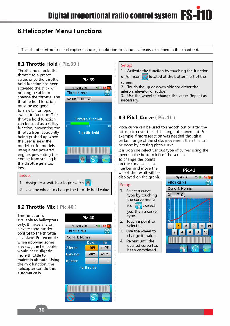
8.1 Throttle Hold(Pic.39)Throttle hold locks the throttle to a preset value, once the throttle hold function has been activated the stick will no long be able to change the throttle. The throttle hold function must be assigned to a switch or logic switch to function. The throttle hold function can be used as a saftey function, preventing the throttle from accidently being pushed up when the user is near the model, or for models using a gas powered engine, preventing the engine from stalling if the throttle gets too low.
Setup:
1. Assign to a switch or logic switch .
2. Use the wheel to change the throttle hold value.
8.2 Throttle Mix(Pic.40)
This function is available to helicopters only. It mixes aileron, elevator and rudder control to the throttle as a slave. For example, when applying some elevator, the helicopter would need slightly more throttle to maintain altitude. Using the mix function, the helicopter can do this automatically.
Setup:
1. Select a curve type by touching the curve menu icon , select yes, then a curve type.
2. Touch a point to select it.
3. Use the wheel to change its value.
4. Repeat until the desired curve has been completed.
8.Helicopter Menu Functions
This chapter introduces helicopter features, in addition to features already described in the chapter 6.
8.3 Pitch Curve(Pic.41)
Pitch curve can be used to smooth out or alter the rotor pitch over the sticks range of movement. For example if more reaction was needed though a certain range of the sticks movement then this can be done by altering pitch curve.It is possible select various type of curves using the menu at the bottom left of the screen.
Pic.39
Pic.40
Pic.41
Setup:1. Activate the function by touching the function on/off icon located at the bottom left of the screen. 2. Touch the up or down side for either the aileron, elevator or rudder.3. Use the wheel to change the value. Repeat as necessary.
To change the points on the curve select a number and move the wheel, the result will be displayed on the graph.

31
This function is used for adjusting the gyro sensitivity. If the sensitivity is too high the helicopter will oscillate (Tail moving from side to side) and if the sensitivity is too low the helicopter
2. Select pitch or throttle by touching its box located in the rate column.
3. Use the wheel to change the value.
4. Test and repeat until the model can hover predictably.
Take weather conditions, wind and drafts into account.
This function can be set with up to 5 conditions.
8.4 Swashplate Mix(Pic.42)
Adjust the motion range of these three functions to achieve the desired maneuverability. Refer to your models manual to ensure best results.
Setup:
1. Select aileron, elevator or pitch..
2. Move the wheel to modify the value.
3. Repeat as needed.
This function can be set with up to 5 conditions.
8.5 Swashplate Ring(Pic.43)
This function is to limit swash plates range of movement achieve different control difficulties. For example a beginner might use a smaller swashplate ring setting in order to prevent any extreme movement caused by mistakes when flying. The swashplate ring will be displayed on the graph with a real time display of stick movement. When stick movement moves beyond the swashplate ring setting, an X will be displayed showing the swashplate limited
Setup:
1. Activate the function by touched the function on/off icon located at the bottom left of the screen.
2. Move the wheel to change the value.
Pic.42
8.6 Hover Adjust(Pic.44)
If your model is moving up or down, or moving in a direction when hovering, use this function to correct this. If the model is gaining or losing altitude, adjust the throttle setting. If the model is drifting back or forward then adjust the pitch setting.
Setup:
1. Move the wheel to change the value.
2. If required this function can be assigned to a switch or logic switch .
3. Test and repeat until you have the desired result. This function can be set with up to
8.7 Gyroscope (Pic.45)
Pic.43
This function is used to edit the pre-programmed mix control of the helicopter’s aileron, elevator and pitch.
position, however the system will still display the sticks real position, shown as a line leading to a box.
Setup:
1. Assign both throttle control and pitch control in the switch assignment menu [icon].
Pic.44
will be sluggish and unresponsive. The default channel is channel 5.
Pic.45

FS-l10Digital proportional radio control system
32
8.8 Governor(Pic.46)
Setup:
1. Use the wheel to change the value.2. Test and adjust as necessary until you have the desired result. This function can be set with up to 5 conditions.
8.9 Helicopter Structure(Pic.47)Helicopter structure enables you to set the control surfaces on your model. Touch each control surface available on your model so that a tick is displayed in a box next to the name.
8.10 Swashplate Type(Pic.48)
The system supports 7 different types of swash plate, consult your models user manual to determine which type of swash plate you have.
Pic.47 Pic.48
Surface Function Variable pitch Pitch Curve, Swashplate Mix, Swashplate ringThrottle Needle Throttle CurveGyroscope GyroscopeGovernor Governor
Setup:
Touch the relevant swashplate type for your model. The currently selected swashplate type will be highlighted in yellow.
The function of a governor is to keep the head speed constant, independent of varying load on the motor. A constant RPM is a good thing for 3D flight since the cyclic and rudder functions (and gyro gain) will remain constant throughout the entire flight envelope. Depending on the size of the helicopter the governors responsiveness needs to be adjusted in order to stop the helicopter from oscillating (The tail moving from side to side) or being too sluggish. The governor channel is channel 9.
Pic.46

33
9. RX Setup
This chapter introduces receiver features.
9.1 Bind with a ReceiverThis menu is for binding the transmitter and receiver. For instructions on binding, please refer to [4.2 Binding].
9.2 RF StdThis menu allows you to change the communication protocol for the transmitter. Select the protocol according to the table below:
RF Standard Receiver TypeAFHDS GR3F,GR3E,R9B,R6B,R6CAFHDS 2 iR4,iR4B,iR6B,iR10AFHDS 2A 1-way A3, A6AFHDS 2A 2-way iA4B, iA6, iA6B, iA10, iA10B,X6
9.3 RX PPM OutputPPM is capable of transferring all channels through one physical output. When [RX PPM output] is checked, the receiver outputs PPM on CH1 output and the other outputs are disabled.To enable PPM output, touch [RX PPM output] in this menu. When the box is checked, the PPM is active.
9.4 RX Battery Monitor (Pic.49)This function is used to monitor the receiver battery voltage. Use the supplied battery’s user manual to set the lower and higher voltages, so that the system can monitor battery level effectively.Setting the voltage alarm sets a custom low battery level alarm.
Pic.49
• AFHDS 2A 2-Way is the latest, most stable and advanced communication protocol. • When changing mode, a confirmation message will display.
You can set the following parameters in this menu:
• External sensor: Enables monitoring battery status using an external sensor.
• Low voltage: Sets your battery’s low voltage value which is 4.00V by default.
• Alarm voltage: Sets the low voltage alarm limit. • High voltage: Set the maximum voltage when the battery is full. The
default high voltage is 5.00V (Check your battery specifications). To change settings, touch the desired item and move the wheel to set the new value.
9.5 Low Signal AlarmThis function is used to enable or disable the low signal alarm function. [Low Signal] When checked, will alert the user with an alarm if the receiver signal strength is less than or equal to 4.

FS-l10Digital proportional radio control system
34
Types of sensors:
[TX Voltage]:Displays the transmitter’s voltage supply.[RX Voltage]:Displays the receiver’s voltage supply. [Signal Strength]:Displays how strong the signal is between the transmitter and receiver. This is measured on a scale of 0 to 10, 10 being the best and 0 being the worst signal strength. When the signal drops to 4 or below the system will alert the user via an alarm. The signal strength is calculated using the SNR (Signal To Noise Ratio) etc.[SNR](Signal To Noise Ratio):The SNR gives an indication of how much signal noise in comparison to clean signal. The more noise there is in the signal, the more likely you will have problems, like losing connection with the receiver. Noise is usually created by other nearby transmitters, such as WI-FI, as such in an area that has a lot of transmitters will have a higher SNR. The SNR is calculated as SNR = RSSI - Noise, if the SNR drops to 4 or below, bring the model closer to you in order to avoid unintended operation.[RSSI](Receiver Signal Strength Indication):RSSI is used to measure signal strength between the receiver and the transmitter. [Noise]:Noise is caused by other transmitter’s, such as wifi. If there is too much noise in an area, this will affect the transmitters maximum range.
Setup:
1. Select a channel. 2. Select the icon at the bottom left of the screen, if it has a tick, it is
active. 3. Set the value by moving the channel to the desired position using the
stick/knob it is assigned to.
4. Use the icon to return to the failsafe channel list.
You can set the failsafe position for all channels with the [All channels] button at once. To do so,
1. Move all your channels to the desired position.2. Select [All channels] and then [Yes] in the confirmation box.
• Once the failsafe has been set, a percentage will be displayed.
9.6 Failsafe (Pic.50)This function is used to protect the models and users, if the receiver loses signal and therefore is no longer controllable. All channels are listed in the failsafe menu. [Off] means that in case of a loss of signal, the corresponding servo will keep its last received position. If it displays a percentage, the servo will instead move to the selected position.
Pic.50
9.7 Display Sensors
This function is used to display information from the current active sensors.[Type]:The type of sensor is displayed on the left hand side under [Type];[ID]:The numerical ID of each sensor is in the middle under [ID],[Value]:the sensor’s output is on the right under [Value]. At the bottom of the list this menu has an error rate display, which is a good indicator of signal quality.
35
To choose a sensor:
1. Select a slot, 1, 2, 3 or 4. Any sensors that are connected will automatically populate this list.2. Select the desired sensor and exit the function.
To set the alarm limits for a sensor:
1. Activate the function. Make sure that the icon is displayed in the bottom left corner. If not, press the
icon to enable.
2. Select [Low alarm] or [High alarm] and then move the wheel to adjust the value.
3. Select the icon to return to the previous menu.
9.8 Choose Sensors The main screen can display the value of up to 4 sensors. This function is used to select which sensors to display.
9.9 Set ASL PressureThe set ASL (Above Sea Level) function is used to calibrate an altitude sensor. When an altitude sensor is connected, change the [Air pressure] setting until the altitude is at 0m.
• Make sure that your model is at ground level during this process.
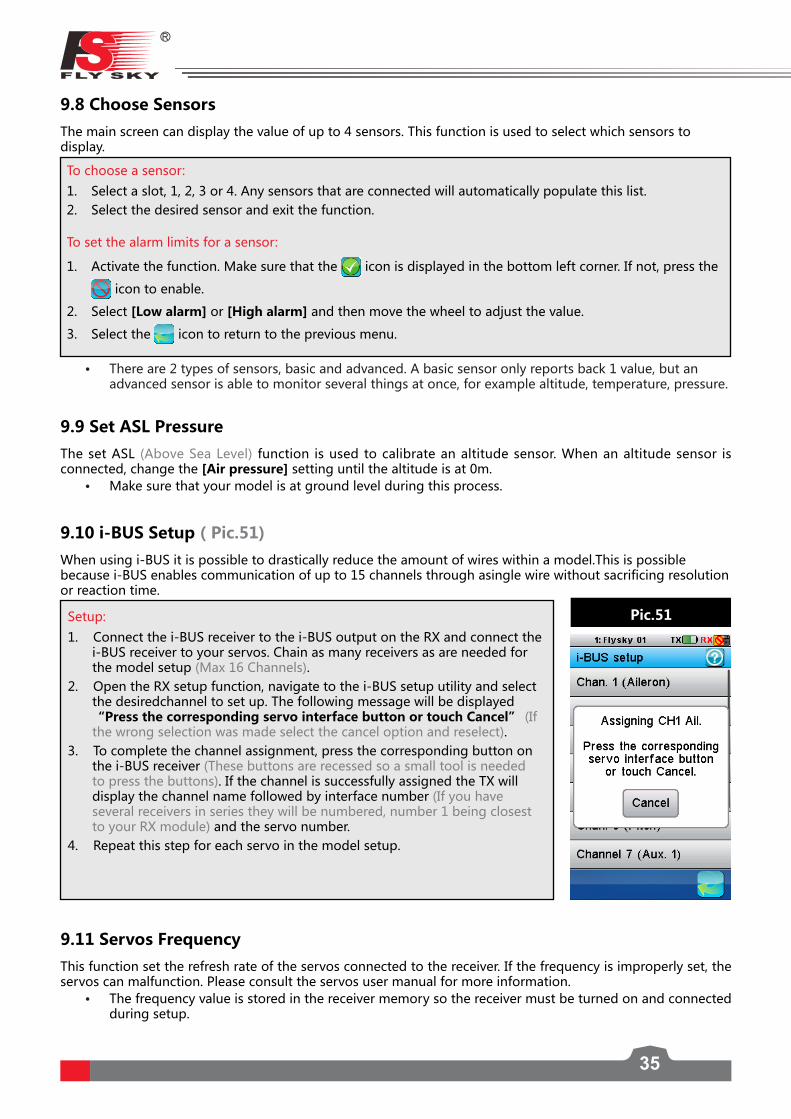
When using i-BUS it is possible to drastically reduce the amount of wires within a model.This is possible because i-BUS enables communication of up to 15 channels through asingle wire without sacrificing resolution or reaction time.
9.10 i-BUS Setup(Pic.51)
Setup:
1. Connect the i-BUS receiver to the i-BUS output on the RX and connect the i-BUS receiver to your servos. Chain as many receivers as are needed for the model setup (Max 16 Channels).
2. Open the RX setup function, navigate to the i-BUS setup utility and select the desiredchannel to set up. The following message will be displayed “Press the corresponding servo interface button or touch Cancel” (If the wrong selection was made select the cancel option and reselect).
3. To complete the channel assignment, press the corresponding button on the i-BUS receiver (These buttons are recessed so a small tool is needed to press the buttons). If the channel is successfully assigned the TX will display the channel name followed by interface number (If you have several receivers in series they will be numbered, number 1 being closest to your RX module) and the servo number.
4. Repeat this step for each servo in the model setup.
Pic.51
• There are 2 types of sensors, basic and advanced. A basic sensor only reports back 1 value, but an advanced sensor is able to monitor several things at once, for example altitude, temperature, pressure.
This function set the refresh rate of the servos connected to the receiver. If the frequency is improperly set, the servos can malfunction. Please consult the servos user manual for more information.
• The frequency value is stored in the receiver memory so the receiver must be turned on and connected during setup.
9.11 Servos Frequency

FS-l10Digital proportional radio control system
36
Setup:After selecting [Update receiver], the FS-i10 will ask for a conformation. Select [Yes].
• If the FS-i10 has an update for the receiver, the update will be displayed as a percentage. when the update is complete the function will exit automatically.
• If no updates are available, the FS-i10 will display [Receivers firmware is already up to date].
9.12 Range TestThis function temporarily reduces the transmitter’s power to allow for a manageable range test. Instead of having to walk several hundred meters away from the receiver, it is possible to test the range by pressing SW2 and walking at most 30 meters away from your model.
9.13 Update ReceiverThis function is used to update the firmware of the receiver.

37
10. System Settings
The menu system is used to set transmitter functions such as screen and audio settings.
10.1 Blacklight Timeout: (Time)The blacklight timeout function controls how long the system will wait before turning off screens backlight.
• Backlight time can affect the battery life of your system, the longer the time, the shorter the battery will last.To change the backlight time enter the function and select the desired time from the list.
10.2 Backlight: (%)This function controls the backlight brightness. Note that increasing the brightness will reduce battery life.To change the backlight brightness, move the wheel at the bottom of the screen to change the percentage.
10.3 System SoundThis function is used to toggle all system sounds, including power-on/power-off sounds, key sounds and so on. The alarm sound is not included.To disable the system sounds, uncheck the box by touching it.
10.4 Alarm SoundThis function is used to toggle all alarm sounds.To disable the alarm sounds, uncheck the box by touching it.
10.5 Auto Power OffThis function powers off the system automatically after 2 minutes, unless a receiver is connected. To enable this function, check the box by touching it.
10.6 Screen CalibrationIf the touch screen is not functioning correctly, use this function to recalibrate. To recalibrate once inside the function touch the center of the crosses as they appear on the screen. The system will exit the function once calibration is complete.
• It is recommended that you use the supplied stylus to calibrate the screen.
10.7 UnitsThis function is used to change between Metric and Imperial measurement systems.
10.8 USB Function The system can be used with various computer based simulators via USB.
Setup:1. To enable the simulator function select [FS-i10 emulator] from the menu. 2. To disable this function select [None].
• When the emulator mode is active, the system cannot transmit data wirelessly.
To change the system language simply touch the desired language.
10.9 Language
FS-l10Digital proportional radio control system
38
This option contains basic information about the system such as currents hardware and software versions and the TX ID.
10.10 Firmware UpdateThe internal software of the transmitter can be updated using the USB interface connected via a PC computer. Once this function is activated, all functions of the transmitter stop. To avoid any loss of control of the vehicle, turn its receiver off before entering this mode. A confirmation is requested.When the firmware is updating, never disconnect the USB cable or remove the battery or the transmitter will become unusable.
This function can be used only when connected with a computer. Follow the steps as shown below:1. Download and open the newest official software.2. Connect a transmitter with a computer by USB cable.3. Enter [Firmware Update] menu and press [OK] to complete.
10.11 Factory ResetTo reset the system to its factory settings press this option, then select [Yes] to confirm.
10.12 About FS-i10

39
11. Product Specification
This section contains the FS-i10, FS-iA10B and sensor specifications.
11.1 Transmitter Specification (FS-i10)
Channels 10Model type Fixed-Wing/Glider/HelicopterRF range 2.408 ~ 2.475GHzBandwidth 500 KHzBand 135RF power Less then 20 dBm2.4G system AFHDS 2ACode type GFSKStick Resolution 4096Low voltage alarm Yes (lower than 3.75V)DSC port Yes (Micro-USB)Power input 3.7 V (1700 mAh)
Antenna length 26 mm
Weight 720gDimension (Length x Width x Height) 190*95*255 mmColor Silver
DisplayWQGA 3.55inch Touch Resistive TFT Colour Screen, 262k, 240*400 Pixels
Certificate CE0678,FCC:N4ZFLYSKYI10
11.2 Receiver Specification (FS-iA10B) Channels 10Model type Fixed-Wing/Glider/HelicopterRF range 2.408-2.475 GHzBand 135RF power Less than 20 dBm2.4G system AFHDS 2ACode type GFSKPower input 4.0 to 6.5 V DCWeight 17.6gAntenna length 26mm Dimension (Length x Width x Height) 50.6*34.9*14.9 mmColor BlackCertificate CE0678,FCC:N4ZFLYSKYIA10BRX sensitivity -105dBmi-Bus port YesData acquisition port Yes

FS-l10Digital proportional radio control system
40
11.3 Sensor Specification
11.3.1 RPM Telemetry (Magnetic) Module(FS-CPD01)
Model type Car/Boat/PlaneSpeed range 0 to 60000 rpmPower input 4.0 to 6.5 V DCWeight 6.6gDimension (Length x Width x Height) 31*15*8.5 mmColor Black
11.3.2 RPM Telemetry (Optical) Module(FS-CPD02)
Model type Car/Boat/PlaneSpeed range 0 to 60000 rpmPower input 4.0 to 6.5 V DCWeight 6.8gDimension (Length x Width x Height) 31*15*8.5 mmColor Black
11.3.3 Temperature Acuquisition Module(FS-CTM01)
Model type Car/Boat/PlaneTemperature range -40 to 250 ° CPower input 4.0 to 6.5 V DCWeight 5.9gDimension (Length x Width x Height) 31*15*8.5 mmColor Black
11.3.4 Voltage Acquisition Module (FS-CVT01)
Model type Car/Boat/PlaneVoltage range 0 to 100 V DCPower input 4.0 to 6.5 V DCWeight 6gDimension (Length x Width x Height) 31*15*8.5 mmColor Black
11.3.5 Altitude Acquisition Module (FS-CAT01)
Model type Car/Boat/PlaneAltitude range 0to8000m、40to100kpaPower input 4.0 to 6.5 V DCWeight 5.3gDimension (Length x Width x Height) 31*15*8.5 mmColor Black

41
11.3.6 i-Bus Receiver(FS-CEV01)
Model type Car/Boat/PlanePower input 4.0 to 6.5 V DCWeight 7 gDimension (Length x Width x Height) 32*15.6*7.5mmColor Blacki-Bus port YesChannels 1
11.3.7 i-Bus Receiver(FS-CEV02)
Model type Car/Boat/PlanePower input 4.0 to 6.5 V DCWeight 7.6 gDimension (Length x Width x Height) 32*16*10 mmColor Blacki-Bus port YesChannels 2
11.3.8 i-Bus Receiver(FS-CEV04)
Model type Car/Boat/PlanePower input 4.0 to 6.5 V DCWeight 6.8gDimension (Length x Width x Height) 33.2*14.8*7.5mmColor Blacki-Bus port YesChannels 4

FS-l10Digital proportional radio control system
42
Appendix 1 FCC Statement This equipment has been tested and found to comply with the limits for a Class B digital device pursuant to part 15 of theFCC rules. These limits are designed to provide reasonable protection against harmful interference in a residential installation. This equipment generates, uses and can radiate radio frequency energy and, if not installed and used in accordance with the instructions, may cause harmful interference to radio communications. However, there is no guarantee that interference will not occur in a particular installation. If this equipment does cause harmful interference to radio or televison reception, which can be determined by turning the equipment off and on, the user is encouraged to try to correct the interference by one or more of the following measures:
• Reorient or relocate the receiving antenna.• Increase the separation between the equipment and receiver.• Connect the equipment into an outlet on a circuit different from that to which the receiver is
connected.• Consult the dealer or an experienced radio/TV technician for help.
To assure continued compliance, any changes or modifications not expressly approved by the party responsible for compliance could void the user’s authority to operate this equipment. (Example use only shielded interface cables when connecting to computer or peripheral devices).
This equipment complies with Part 15 of the FCC Rules. Operation is subject to the following two conditions:
1. This device may not cause harmful interference, and2. This device must accept any interference received, including interference that may cause undesired
operation.
Caution!
The manufacturer is not responsible for any radio or TV interference caused by unauthorized modifications to this equipment. Such modifications could void the user authority to operate the equipment.
1. Move all your channels to the desired position.2. Select [All channels] and then [Yes] in the confirmation box.

Copyright ©2013-2017 Flysky RC model technology co., ltd
http://www.flysky-cn.com
Edition:2016-06-06