instruction manual - horizonhobbymanuals.hobbico.com/gpm/gpma0480-manual.pdf · the dazzler 40 is...
TRANSCRIPT

WARRANTYGreat Planes Model Manufacturing Co. guarantees this kit to be free from defects in both material and workmanship at the date of purchase. This warranty does not cover any component parts damaged by use or modification. In no case shall Great Planes' liability exceed the original cost of the purchased kit. Further, Great Planes reserves the right to change or modify this warranty without notice.
In that Great Planes has no control over the final assembly or material used for final assembly, no liability shall be assumed nor accepted for any damage resulting from the use by the user of the final user-assembled product. By the act of using the user-assembled product, the user accepts all resulting liability.
If the buyer is not prepared to accept the liability associated with the use of this product, the buyer is advised to return this kit immediately in new and unused condition to the place of purchase.
While this kit has been flight tested to exceed normal use, if the plane will be used for extremely high stress flying, such as racing, the modeler is responsible for taking steps to reinforce the high stress points.
READ THROUGH THIS MANUAL BEFORE STARTING CONSTRUCTION. IT CONTAINS IMPORTANT WARNINGS AND INSTRUCTIONS CONCERNING THE ASSEMBLY AND USE OF THIS MODEL.
© 2011 Hobbico®, Inc. All rights reserved. DAZ4P02 v1.2
P.O. Box 788 Urbana, IL 61803 (217) 398-8970
INSTRUCTION MANUAL
™

2
TABLE OF CONTENTS
Introduction ........................................................................... 2Precautions ........................................................................... 2Decisions You Must Make .................................................... 3 Engine Selection .............................................................. 3Preparations .......................................................................... 3 Required Accessories ...................................................... 3 Building Supplies and Tools ............................................. 3 Optional Supplies and Tools ............................................ 3 Types of Wood ................................................................. 4 Common Abbreviations ................................................... 4 Building Notes.................................................................. 4 Get Ready to Build........................................................... 5 Die-Cut Patterns .............................................................. 5 Inch/Metric Ruler & Conversions ..................................... 5Build the Tail Surfaces ......................................................... 6 Build the Stabilizer ........................................................... 6 Fin and Rudder ................................................................ 7Build the Wing ....................................................................... 7 Ailerons ............................................................................ 7 Wing Panels ..................................................................... 7 Join the Wing Panels ....................................................... 9 Add Wing Sheeting .......................................................... 9Build the Fuselage .............................................................. 10Final Assembly ................................................................... 12Covering & Finishing ......................................................... 14 Final Sanding ................................................................. 14 Fuelproofing ................................................................... 14 Balance the Airplane Laterally ....................................... 14 Cover the Structure with MonoKote® Film ...................... 14 Repairing Surface Dings ................................................ 15 Recommended Covering Sequence .............................. 15Final Hookups & Checks ................................................... 15 Control Surface Throws ................................................. 17 Balance Your Model ....................................................... 18AMA Safety Code (excerpt) ............................................... 18 General .......................................................................... 18 Radio Control ................................................................. 18Preflight ............................................................................... 19 Balance the Prop ........................................................... 19 Charge the Batteries ...................................................... 19 Ground Check the Model ............................................... 19 Range Check Your Radio ............................................... 19 Engine Safety Precautions ............................................ 19Flying ................................................................................... 19 Takeoff .............................................................Back Cover Flying ...............................................................Back Cover Landing ............................................................Back Cover2-View Drawing ....................................................Back Cover
PROTECT YOUR MODEL,YOURSELF & OTHERS...FOLLOW THIS
IMPORTANT SAFETY PRECAUTION
Your Dazzler 40 is not a toy, but a sophisticated, working model that functions very much like a full size airplane. Because of its aerobatic performance, the Dazzler 40, if not
assembled and operated correctly, could possibly cause injury to yourself or spectators and damage property.
If this is your first sport model, we recommend that you get help from an experienced, knowledgeable modeler with your first flights. You’ll learn faster and avoid risking your model before you’re ready to take the controls for yourself.
For information on flying clubs in your area, you can contact the national Academy of Model Aeronautics (AMA), which has more than 2,500 chartered clubs across the country. Contact AMA at the address or toll-free phone number below:
Academy of Model Aeronautics5151 East Memorial DriveMuncie, IN 47302-9252
Tele. (800) 435-9262Fax (765) 741-0057
Or via the internet at: modelaircraft.org
INTRODUCTION
The Dazzler 40 is very stable and forgiving, allowing even intermediate skill level pilots to enjoy it.
This is not a beginner’s airplane! While the Dazzler 40 is easy to build and flies great, we must discourage you from selecting this kit as your first R/C airplane. It lacks the self-recovery characteristics of good basic trainers such as the Great Planes PT™ Series. On the other hand, if you have already learned the basics of R/C flying, and you are able to safely handle a .40-size taildragger, the Dazzler 40 is an excellent choice to try your skills at flying an aerobatic sport airplane.
PRECAUTIONS
1. You must assemble the model according to the instructions. Do not alter or modify the model, as doing so may result in an unsafe or unflyable model. In a few cases the instructions may differ slightly from the photos. In those instances the plans and written instructions should be considered as correct.
2. Take time to build straight, true and strong.
3. Use an R/C radio system that is in first-class condition, and a correctly sized engine and components (fuel tank, wheels, etc.) throughout your building process.
4. You must properly install all R/C and other components so that the model operates properly on the ground and in the air.

3
5. You must test the operation of the model before every flight to insure all equipment is operating, and you must make certain the model has remained structurally sound. Be sure to check clevises or other connectors often and replace them if they show signs of wear or fatigue.
NOTE: We, as the kit manufacturer, provide you with a top quality kit and great instructions, but ultimately the quality of your finished model depends on how you build it; therefore, we cannot in any way guarantee the performance of your completed model, and no representations are expressed or implied as to the performance or safety of your completed model arirplane.
Remember: Take your time and follow directions to end up with a well-built model that is straight and true. Please inspect all parts carefully before starting to build! If any parts are missing, broken or defective, or if you have any questions about building or flying this airplane, please call us at (217) 398-8970. If you are calling for replacement parts, please reference the part numbers and the kit identification number (stamped on the end of the carton) and have them ready when calling.
We can also be reached by E-Mail at:
DECISIONS YOU MUST MAKE
Engine Selection
There are several engines that will work well in your Dazzler 40. We recommend a hot 2-stroke such as an O.S.® .40FX or SuperTigre™ G45. For unsurpassed power and realistic sound, an O.S. FS-52 Surpass™
4-stroke can’t be beat. The engine you select will determine how you build the firewall section, so it is important that you have the engine close at hand while building.
PREPARATIONS
Required AccessoriesItems in parentheses (GPMQ4243) are suggested part numbers recognized by distributors and hobby shops and are listed for your ordering convenience. GPM is the Great Planes brand, TOP is the Top Flite® brand, and HCA is the Hobbico® brand.
❏ Four-channel radio with five servos ❏ Engine – See Engine Selection above ❏ Propeller (Top Flite® Power Point™); Refer to your
engine’s instructions for proper size
❏ Fuel tank 6 oz. (SULQ1426) ❏ Medium fuel tubing (GPMQ4131) ❏ 2-1/2" Main wheels (DUBQ0875) ❏ 1" Tailwheel (GPMQ4241) ❏ Top Flite MonoKote® (2 to 3 rolls) ❏ 1/4" Latex foam rubber padding (HCAQ1000) ❏ Switch and Charge Jack (GPMM1000) ❏ (4) 4-40 Blind Nuts (GPMQ3324) ❏ Engine Mount .20 to .48 (GPMG1041) ❏ (4) 4-40 x 1" Machine Screws (GPMQ3016) ❏ 24" Flex Cable Pushrod (GPMQ3700)
Building Supplies and Tools
These are the building tools that are required. We recommend Great Planes Pro™ CA and Epoxy glue.
❏ 2 oz. Pro CA (Thin, GPMR6003) ❏ 2 oz. Pro CA+ (Medium, GPMR6009) ❏ 6-Minute Pro Epoxy (GPMR6045) ❏ 30-Minute Pro Epoxy (GPMR6047) ❏ Hand or electric drill ❏ Sealing iron (TOPR2100) ❏ Heat gun (TOPR2000) ❏ Hobby saw ❏ Hobby knife, #11 Blades (HCAR0311) ❏ Razor plane (Master Airscrew®) ❏ Pliers (Common and Needle Nose) ❏ Screwdrivers (Phillips and flat tip) ❏ T-pins (HCAR5150) ❏ 60" Retractable Tape Measure (HCAR0478) ❏ Straightedge with scale ❏ Masking tape (GPMR1010) ❏ Sandpaper (coarse, medium, fine grit) ❏ Easy-Touch™ Bar Sander (or similar) ❏ Plan Protector (GPMR6167) ❏ Lightweight balsa filler such as Hobbico® HobbyLite™
(Hobbico HCAR3400) ❏ 1/4-20 Tap and Drill (GPMR8105) ❏ Isopropyl rubbing alcohol (70%) ❏ Ballpoint pen ❏ 90° Building square (HCAR0480) ❏ Canopy glue ❏ Drill bits: 1/16", 1/8", 5/32", 3/16", 1/4"
Optional Supplies and Tools ❏ CA Applicator Tips (HCAR3780) ❏ Epoxy brushes (GPMR8060) ❏ Epoxy mixing sticks (GPMR8055) ❏ CA Debonder (GPMR6039) ❏ Hot Sock™ (TOPR2175) ❏ Single-edge razor blades (HCAR0312) ❏ Curved tip canopy scissors for trimming plastic parts
(DTXR1150) ❏ 4 oz. Pro Wood Glue (GPMR6161)

On our workbench, we have three 11" Great Planes Easy-Touch Bar Sanders, equipped with 80, 150 and 220-grit sandpaper. This setup is all that is required for almost any sanding task. We also keep some 320-grit wet-or-dry sandpaper handy for finish sanding before covering.
Great Planes Easy-Touch Bar Sanders are made from lightweight extruded aluminum and can be found at most hobby shops. They are available in five sizes – 5-1/2" (GPMR6169) for those tight, hard-to-reach spots; 11" (GPMR6170) for most general purpose sanding; and 22" (GPMR6172), 33" (GPMR6174) and 44" (GPMR6176) for long surfaces such as wing leading edges. The Easy-Touch Adhesive-Backed Sandpaper comes in 2" x 12' rolls of 80-grit (GPMR6180), 150-grit (GPMR6183), 180-grit (GPMR6184) and 220-grit (GPMR6185) and an assortment of 5-1/2" long strips (GPMR6189) for the short bar sander. The adhesive-backed sandpaper is easy to apply and remove from your sanding bar when it’s time for replacement.
Custom sanding blocks can be made from balsa or hardwood blocks and dowels for sanding difficult to reach spots.
Types of Wood
Balsa Basswood Plywood
Common Abbreviations
Elev = Elevator Fuse = Fuselage LE = Leading Edge (front) LG = Landing Gear Ply = Plywood Stab = Stabilizer TE = Trailing Edge (rear) " = Inches
Building Notes
There are two types of screws used in this kit:
Sheet metal screws are designated by a number and a length. For example #6 x 3/4"
Machine screws are designated by a number, threads per inch and a length. For example 4-40 x 3/4"
When you see the term “test fit” in the instructions, it means you should first position the part on the assembly without using any glue and then slightly modify or sand the part as necessary for the best fit.
Whenever the instructions tell you to glue pieces together, CA or epoxy may be used. When a specific type of glue is required, the instructions will state the type of glue that is highly recommended. When 30-minute epoxy is specified, it is highly recommended that you use only 30-minute (or slower) epoxy because you will need either the working time or the additional strength.
Several times during construction we refer to the “top” or “bottom” of the model or a part of the model. For example, during wing construction we tell you to “glue the top main spar” or “trim the bottom of the former.” It is understood that the “top” or “bottom” of the model is as it would be when the airplane is right side up and will be referred to as the “top” even if the model is being worked on upside down (i.e. the “top” main spar is always the “top” main spar, even when the wing is being built upside down).
4

5
Get Ready to Build
❏ 1. Unroll the plan sheet. Reroll the plan sheet inside out to make it lie flat. Place wax paper or Great Planes Plan Protector over the area of the plan you are working on to prevent glue from sticking to the plan. Use tape or tacks to hold the plan and protector securely in place.
❏ 2. Remove all parts from the box. As you do, determine the name of each part by comparing it with the plan and the parts list included with this kit. Using a felt-tip or ballpoint pen, lightly write the part name or size on each
piece to avoid confusion later. Use the die-cut patterns shown below to identify the die-cut parts and mark them before removing them from the sheet. Save all scraps. If any of the die-cut parts are difficult to remove, do not force them! Instead, cut around the parts. Use your Easy-Touch Bar Sander or sanding block to lightly sand the edges to remove any die-cutting irregularities.
❏ 3. As you identify and mark the parts, separate them into groups, such as fuse (fuselage), wing, fin, stab (stabilizer) and hardware. Resealable food storage bags are handy to store parts as you sort, identify and separate them into subassemblies.
0" 1" 2" 3" 4" 5" 6" 7"
0 10 20 30 40 50 60 70 80 90 100 110 120 130 140 150 160 170 180
Inch Scale
DIE-CUT PATTERNS
Metric Conversions 1/64" = .4 mm 1/32" = .8 mm 1/16" = 1.6 mm 3/32" = 2.4 mm 1/8" = 3.2 mm 5/32" = 4.0 mm 3/16" = 4.8 mm
1/4" = 6.4 mm 3/8" = 9.5 mm 1/2" = 12.7 mm 5/8" = 15.9 mm 3/4" = 19.0 mm 1" = 25.4 mm 2" = 50.8 mm 3" = 76.2 mm
6" = 152.4 mm 12" = 304.8 mm 18" = 457.2 mm 21" = 533.4 mm 24" = 609.6 mm 30" = 762.0 mm 36" = 914.4 mm

6
BUILD THE TAIL SURFACES
Build the Stabilizer
(Refer to this photo for the following 3 steps.)
❏ 1. After covering the plan with wax paper, pin the shaped 1/4" balsa stab center section over its location on the plan. Use 1/4" x 1/2" x 30" balsa to build the outer framework of the stabilizer and both elevators, gluing each piece in position as you proceed.
❏ 2. Cut and install four corner gussets and two elevator joiner wire gussets from 1/4" x 1" x 24" balsa.
❏ 3. Cut and install the 1/4" x 1/4" and 1/4" x 3/16" internal bracing as shown on the plan.
❏ 4. Remove the stabilizer and elevators from the plan and attach them with masking tape, making sure the outer edges are flush. Position the 1/8" elevator joiner wire over the elevators as shown on the plan. Mark the location of the joiner wire.
❏ 5. While the parts are taped together, round off all outside edges around the perimeter of the assembly.
❏ 6. Remove the elevators. Drill a 1/8" hole (1" deep) through the center of each elevator’s leading edge at the locations you marked in step #4. Cut a groove from the hole you drilled to the root end of each elevator. The groove will allow the joiner wire to fit flush with the elevator’s leading edge.
Use the expert tip shown below to assist you in cutting the groove.
HOW TO CUT A GROOVE FOR A TORQUE ROD
A. Use a hobby knife to sharpen the inside of a piece of 1/8" brass tube. Roll the tube as you carve the end.
B. Use the sharpened tube to carefully gouge the leading edge. You’ll have to make several passes to make the recess deep enough for the torque rod.
❏ 7. Draw a centerline on the leading edge of both elevators. Refer to the cross section on the plan, then sand the elevator leading edges to a “V” shape.

7
❏ 8. Test fit the joiner wire into both elevators. Make sure that both elevators are flat on the work surface and the tips of the elevators align with the tips of the stab. If necessary, remove the joiner wire, then make adjustments by bending the wire.
❏ 9. Roughen the joiner wire with coarse sandpaper. Pack 30-minute epoxy into the elevator’s holes with a toothpick, then permanently install the joiner wire. Be sure the elevators are flat on the work surface and the leading edge is perfectly straight.
Fin and Rudder
❏ 1. Working over the waxed paper covered plan, assemble the outside framework of the fin and rudder using 1/4"x 1/2" x 30" balsa.
❏ 2. Add the corner gussets cut from 1/4" x 1" balsa.
❏ 3. Add the 1/4" x 3/16" balsa internal bracing.
❏ 4. Remove the rudder and fin from the plan. Using the plan for reference, mark and drill a 1/8" hole (3/4" deep) into the lower leading edge of the rudder to accept the tail gear torque arm. Cut a groove from the hole to the bottom of the rudder for the tail gear bearing.
❏ 5. Refer to the cross section on the plan, then round off the leading and top edge of the fin and the trailing and top edge of the rudder with sandpaper. Shape only the leading edge of the rudder to a “V” along the hinge line.
BUILD THE WING
Ailerons
❏ ❏ 1. Working over the waxed paper covered plan, build an aileron frame from 1/4" x 1/2" balsa (the ends are at 45° angles).
❏ ❏ 2. Add the 1/4" x 1/2" internal bracing. Carefully cut and install the aileron control horn brace using 1/4" x1" balsa.
❏ ❏ 3. Remove the aileron from the plan and draw a centerline on the leading edge of both ailerons. Sand the leading edge of the ailerons to a “V” shape as shown on the plan.
❏ ❏ 4. Don’t round off the trailing edge of the aileron. Just knock off the corners.
❏ 5. Build the second aileron frame over the same plan (repeat steps 1 through 4).
Wing Panels
Before building the wing it is necessary to cut the right wing tip from the plan and tape it into position. Use care to make sure the plan is aligned correctly before taping it. The wing panels will be assembled in two parts and joined later.
❏ 1. Trim the four 1/4" x 1/4" x 30" basswood wing spars down to a length of 24". Save the remaining 6" pieces for later use.

8
❏ ❏ 2. Cover the right wing plan with waxed paper. Use cross-pinning (see illustration) to hold a wing spar in position where shown on plan. The spar should be even with the wing’s centerline and tip.
❏ ❏ 3. Cut the four 1/16" x 1-1/8" x 30" balsa trailing edge sheets down to 24". Pin one sheet over the plan flush with the trailing edge of the wing. NOTE: These sheets extend past the aft edge of the ribs by 1/4".
❏ ❏ 4. Position the die-cut R1 (see note) through R3 wing ribs on the spar at the locations shown. Be sure the flat portion of the airfoil is toward the building board and the ribs are fully seated on the spar. Use a small drafting triangle to hold each rib vertical while you glue it in position. NOTE: The main spar is centered in the spar notch in the R1 rib to allow room for the spar joiners to fit on both sides of the spars.
❏ ❏ 5. Cut a 24" trailing edge stick from a piece of 1/4" x 3/8" x 30" balsa. Glue the trailing edge (3/8" dimension is vertical) to the ribs and bottom trailing edge sheeting. Sand the top of the trailing edge (with a long sanding block) flush with the top of the ribs at an angle that matches the slope of the airfoil.
❏ ❏ 6. Cut two 24" sub-leading edges from the 1/16" x 1" x 30" balsa sheets. Center the sub-leading edge vertically on the front of the ribs (and flush with the wing’s centerline), then glue it in position. Remove the wing from the plan and sand the top and bottom edges of the sub-leading edge flush with the top and bottom of the airfoil.
❏ ❏ 7. Cut two 5/16" x 1-3/16" x 30" balsa leading edges to 24". Vertically center, then glue, a leading edge to the sub-leading edge of the wing panel.
❏ ❏ 8. Glue the 1/4" x 1/4" x 24" top basswood spar in position. Use a drafting triangle to be sure the root end is even with the bottom spar.
❏ ❏ 9. Use the leftover 1/4" basswood spar material to make two aileron servo rails 1-5/8" long. Insert the rails into the notches between the closely spaced R2 ribs. Use a servo of your choice to set the correct spacing between the rails, then glue the rails securely in position.

9
❏ 10. Remove the wing panel from the plan and set it aside. Follow steps 2 - 9 to build the left wing panel using the extra pieces you cut previously.
Join the Wing Panels
❏ 1. Pin both wing panels down onto the plan, checking the alignment of each panel. Test fit the die-cut 1/8" ply leading and trailing edge joiners and the four 1/16" x 1/4" x 6-1/2" ply main spar joiners in the wing. Test fit the die-cut plywood servo tray between the R1 ribs. Use a metal straightedge to make sure the spars, leading edge and trailing edge are aligned and straight. When everything fits well, glue the servo tray to both R1 ribs, then remove the joiner pieces in preparation for gluing.
❏ 2. Be sure the wing is right-side up and flat on the workbench. Use 30-minute epoxy to glue the leading and trailing edge joiners in position. Next, install the top and bottom main spar joiners, also using 30-minute epoxy. Double check that there is no twisting or bowing and that everything is straight before the epoxy cures.
Add Wing SheetingBe sure the wing is pinned flat on your work surface from the spar to the trailing edge before you begin sheeting.
❏ 1. Glue a 1/16" x 1-1/8" x 24" trailing edge sheet to the top of both wing panels.
❏ 2. Trim the four 1/16" x 3" x 30" balsa leading edge sheets to 24". Save the leftover 6" pieces for use later during construction. Cut the 3" x 24" pieces down to 2-3/8" x 24". Save the 5/8" x 24" sticks to make the R1 cap strips.
❏ ❏ 3. Align a leading edge sheet with a wing tip, then hold it tightly against the leading edge while using thin CA to glue it to the sub-leading edge. (See photo at step 5.)
❏ ❏ 4. Carefully lift up the leading edge sheet, away from the ribs. Working quickly, apply a bead of medium or thick CA to each rib, then roll the sheet into contact. Hold the sheet until the CA cures. Wick some thin CA between the sheet and the spar to glue the aft edge of the sheet to the spar.
❏ ❏ 5. Glue a scrap piece of 1/16" x 1/2" x 2" balsa to the bottom edge of the leading edge sheet at the root end to reinforce the joint between the leading edge sheets. Sheet the other top leading edge by repeating steps 3 and 4.
❏ ❏ 6. Cut and install cap strips for the top of each R2 and R3 rib from 1/16" x 5/16" x 30" balsa sticks. Use the 1/16" x 1/2" x 24" balsa left over from the leading edge sheeting to make the R1 cap strips. Refer to the photo and plan for the correct position of the root and tip cap strips.
❏ ❏ 7. Use the leftover 1/16" x 3" x 6" leading edge sheeting to cut and install shear webs on the aft edge of the spars as shown on the plan.
❏ ❏ 8. Remove the wing from your work surface. Pin it back to your building board, upside-down, making sure it’s straight without any twists.
❏ 9. Repeat steps 3 - 8 to sheet the bottom of the wing.
❏ 10. Use the leftover cap strip balsa to frame the servo openings on the bottom of the wing as detailed on the plan.

10
❏ 11. Use a razor plane or carving blade and coarse sandpaper to shape the leading edge. Cut the template from the plan. Glue it to a piece of scrap cardboard. Use it to test the accuracy of your work as you proceed.
❏ 12. Cut two 4-1/4" x 11" strips from an 8-1/2" x 11" sheet of paper. Roll the strips lengthwise into tubes, and insert them through the holes in the wing ribs between the servo bay and W1. Apply a couple of drops of medium CA to secure their position. These tubes make it easy to install your servo wires.
BUILD THE FUSELAGE
❏ 1. Cover the fuselage top view on the plan with waxed paper. Designate a right and left die-cut balsa fuselage side. If you look at the rear end of the fuse sides you will see three die-cut lines. These lines show the pushrod exits. Use a hobby knife to cut between the top and middle lines on the right fuse side to open an exit slot 1-1/4" long for the elevator pushrod. Perform the same procedure between the middle and bottom lines on the left fuse side for the rudder pushrod exit.
❏ 2. Align and glue the top, bottom and aft die-cut balsa doublers to the die-cut balsa right fuse side as shown. Be
sure the notches on the doublers match the fuse sides perfectly. Repeat this operation for the left fuse side but be sure to check your work before using any glue so that you don’t make two right sides! The doublers must face toward the inside of the model.
❏ 3. Drill a 3/16" pushrod hole through each of the punch marks on die-cut ply formers, F2 through F5. Without using any glue, insert the formers into the notches in the fuse sides with the die-stamped numbers facing the rear of the model and all of the 3/16" pushrod holes toward the bottom of the fuselage. Use masking tape to hold the assembly together.
❏ 4. Position F2 over its location on the plan, then pin the fuse sides to the building surface. Carefully align the length of the fuse over the plan, squaring up the formers and pinning the assembly in place as you proceed. Be sure the front and rear ends are aligned and the fuse is not twisted.
❏ 5. Once satisfied the fuse is trued up, wick some thin CA into all of the joints between the fuse side and formers.
❏ 6. Glue the shaped balsa tail post between the fuse sides, flush with the rear end of the fuse sides. Check to make sure the tail post is vertical with a drafting triangle before the glue cures. After the glue has cured, remove the fuselage from the plan.

11
❏ 7. Cut two 18" pieces from the 36" outer pushrod tube. Sand the outside of the tubes to create a better surface for gluing, then slide the tubes through the holes in the formers and out through the pushrod exits at the rear of the fuse. Glue the tubes to the formers and exit slots with medium CA.
❏ 8. Cut the rear hatch rail from 1/4" x 1/4" basswood leftover from a main spar. Glue it in position into the notches in the fuse doubler at F3. Cut two side hatch rails 1/4" x 1/4" x 7-1/8" from an 18" basswood stick. Glue them in position to the inside of the fuse. Cut the front hatch rail (to match the plan) from 1/4" x 1/4" basswood left over from a main spar. Glue it in position.
❏ 9. Use 6-minute epoxy to glue the 1/8" birch ply landing gear plate into the notches ahead of F2 and to the forward edge of F2. Wipe off any excess epoxy before it cures with a paper towel and rubbing alcohol.
❏ 10. Use CA to glue the die-cut 1/8" ply forward fuse bottom in position. Hold the fuse sides in tight contact while the CA cures.
❏ 11. Sheet the fuse bottom from the rear edge of F3 to the tail post with 3/32" x 3" x 24" cross-grain sheeting. The sheeting from F2 to the hatch rail will be completed after the wing is installed.
❏ 12. Use the firewall cross section on the plan to draw two center lines on the 1/4" birch ply firewall. Center your engine mount on these lines and mark the location of the mounting holes. Drill 1/8" holes through these marks and install 4-40 blind nuts (not included) on the back side of the firewall. Drill a 3/16" hole for the throttle pushrod. Now would also be a good time to drill 1/4" holes for your fuel and vent lines.
❏ 13. Use 6-minute epoxy to glue the firewall between the fuse sides and to the fuse bottom. Secure the firewall with tape, clamps or rubber bands until the epoxy has fully cured.
❏ 14A. Use 6-minute epoxy for the following operations. Cut and glue two pieces of 3/8" triangular balsa to the fuse sides and the firewall between the fuse doublers. Cut and glue two pieces of triangular balsa to the landing gear plate and the fuse doublers.
❏ 14 B. Remove the left and right cockpit floor from the die sheet. Test fit the two pieces, making sure they fit together without any gaps. Glue the two pieces together by wicking thin CA into the joint.

12
❏ 14 C. Test fit the cockpit floor to the top of the fuselage. It may be necessary to slightly spread the two fuse sides at the rear to allow a 1/16" edge from F3 to the location for the canopy backrest. Glue the cockpit floor to the top of the fuselage using medium CA.
❏ 15. Cut and glue a 1/4" x 1/4" basswood hatch rail to fit between the fuse sides in front of F2. Sand the top of the rail to match the tapered angle of the fuse.
❏ 16. Position a sheet of 3/32" x 4" wide balsa over the fuel tank compartment with an edge butted against the top sheeting at F2. The grain must run from front to rear. Trace the outline on the bottom surface, then cut and sand the hatch to fit. Drill four 1/16" pilot holes through the top of the hatch into the hatch rail and firewall at the locations shown for the #2 x 3/8" sheet metal screws.
❏ 17. Test fit the canopy backrest former into position. Use the Backrest Gauge to set the correct angle of the former. After checking to make sure the former is aligned to both sides of the cockpit floor, glue the backrest into position. Glue the gauge into position to help support the former and prevent it from getting accidentally knocked out of position.
FINAL ASSEMBLY
IMPORTANT: The wing is designed to fit snugly into the fuse to provide a good glue joint between it and the fuse sides. Work slowly and carefully when sliding the wing into location to avoid damaging the cap strips or ribs. If too much resistance is felt, remove the wing, then sand the inside of the opening in the fuse to enlarge it slightly.
❏ 1. With one wing tip on the floor, work the fuse down the wing from the opposite end. Due to the close fit, the fuse must be kept perpendicular to the wing or it will bind. You will probably need to help each cap strip through the fuse so take your time and work carefully.
❏ 2. Once the wing is centered in the fuse, measure the distance from each wing tip to the tail post. Shift the wing until the measurements are equal. Mark the location of the throttle pushrod through the F2 former onto the leading edge of the wing. Slide the wing out of the fuse, far enough to drill the location marked, using a 3/16" drill bit. Return the wing to its previous location. When the wing alignment is correct, use medium CA to securely glue the circumference of the R1 ribs to the fuse. Fill any gaps with thick CA.
13
❏ 3. Center the stabilizer on the stab saddle and temporarily pin it in position. Measure from each stab tip to the center of the firewall to set the correct alignment. Draw a couple of reference marks on the stab and fuse sides once it is in position. Look at the rear of the model from several feet away. The stab must be parallel with the wing. See photo at next step. If not, lightly sand the high side of the stab saddle to correct the problem. Once the stab is fully aligned, use 30-minute epoxy to glue the stab in position. Hold it in position with masking tape and pins until the epoxy has cured.
❏ 4. Pin the fin on the centerline of the stab. Check its alignment with the centerline of the fuse with a long straightedge, then mark its aligned location. Glue the fin to the stab with 6-minute epoxy. Make sure the fin is square to the stab with a drafting triangle, then pin and tape the fin in position until the epoxy cures.
❏ 5. Finish sheeting the bottom of the fuse with 3/32" x 3" balsa sheet from F2 to just past the front edge of the front bottom hatch rail.
❏ 6. Cut the bottom hatch cover from 3/32" x 4" balsa. Fit the hatch, then drill 1/16" pilot holes through the hatch and hatch rails. TIP: Use leftover balsa to reinforce the hatch cover by applying two or three cross-grain strips to the inside surface.
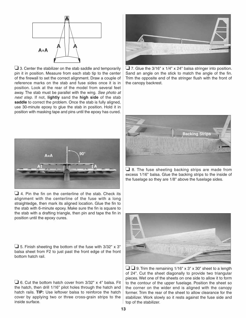
❏ 7. Glue the 3/16" x 1/4" x 24" balsa stringer into position. Sand an angle on the stick to match the angle of the fin. Trim the opposite end of the stringer flush with the front of the canopy backrest.
❏ 8. The fuse sheeting backing strips are made from excess 1/16" balsa. Glue the backing strips to the inside of the fuselage so they are 1/8" above the fuselage sides.
❏ ❏ 9. Trim the remaining 1/16" x 3" x 30" sheet to a length of 24". Cut the sheet diagonally to provide two triangular pieces. Wet one of the sheets on one side to allow it to form to the contour of the upper fuselage. Position the sheet so the corner on the wider end is aligned with the canopy former. Trim the rear of the sheet to allow clearance for the stabilizer. Work slowly so it rests against the fuse side and top of the stabilizer.

14
❏ ❏ 10. Using masking tape, secure the lower edge of the sheeting in position. Do not glue the sheet into position, as it will not conform correctly if glued from the bottom up. Rub a piece of chalk along the top stringer. Carefully shape the sheeting to the contour of the former, pressing it against the top stringer. Remove the sheet, and cut it along the chalk line.
❏ 11. Glue the sheet into position, starting from the top stringer. Work slowly, fitting the sheet as you go. Once the sheet is in position, return to step 9 and repeat the process for the opposite side. Trim and sand the sheeting flush to the front of the canopy former.
❏ 12. Attach the main landing gear using four nylon straps and eight #2 x 3/8" sheet metal screws.
COVERING & FINISHING
We recommend using a lightweight film covering material such as MonoKote® film to finish your Dazzler. For best results, apply the film following the manufacturer’s instructions using the sequence we suggest on page 15.
Final Sanding
Fill any scuffs, dings and the forward end of the pushrod tube exit slots with balsa filler. After the filler has hardened, cut and sand the pushrod tubes flush with the fuse sides, then sand the entire structure with progressively finer grades of sandpaper, ending with 320-grit.
FuelproofingFuelproof the firewall and fuel tank compartment by painting them with thinned 30-minute epoxy. Prevent the epoxy from clogging the blind nuts by first packing the holes with petroleum jelly applied with a toothpick. Be sure to clean off any “external” petroleum jelly “messes” with rubbing alcohol before fuelproofing.
Balance the Airplane LaterallySPECIAL NOTE: Do not confuse this procedure with “checking the C.G.” or “balancing the airplane fore and aft.” That very important step will be covered later in the instruction manual.
❏ 1. Install the engine (with muffler) and landing gear to the fuselage.
❏ 2. With the wing level, lift the model by the engine propeller shaft and the fin (this may require two people). Do this several times.
❏ 3. If one wing always drops when you lift the model, it means that side is heavy. Balance the airplane by gluing a weight to the inside of the other wing tip. NOTE: An airplane that has been laterally balanced will track better in loops and other maneuvers.
Cover the Structure with MonoKote® Film
The Dazzler does not require any painting to obtain the scheme shown on the box, as all of the finish is done with MonoKote Film.
Make sure the structure is smoothly sanded with 320-grit sandpaper. Remove all dust from the structure with a vacuum cleaner and Top Flite® Tack Cloth so the MonoKote film will stick well. Cover the aircraft with MonoKote film using the sequence that follows. Make sure the MonoKote film is thoroughly stuck to the structure and all of the edges are sealed. Use a Top Flite Hot Sock™ on your covering iron to avoid scratching the finish.
When covering areas that involve sharp junctions, like the tail section or around the root of the wing, cut narrow strips (1/4" to 3/8") and apply them in the corners before covering the major surfaces. The larger pieces of MonoKote film will overlap and capture these smaller pieces. This technique also bypasses the need to cut the MonoKote film in these areas after it has been applied. DO NOT, under any circumstances, attempt to cut the covering material after it has been applied to the fin and stab, except around the leading and trailing edges.

15
Repairing Surface Dings
Here is an easy method to remove minor dents in wood where the wood grain has not been broken.
A. Wet the area of the dent with water.
B. Carefully rub a hot sealing iron over the dent.
C. As the wet wood is heated, the wood grain will swell up.
D. Allow the wood to dry before sanding smooth.
Recommended Covering Sequence
❏ 1. Tail junction strips as described above❏ 2. Wing/fuse junction❏ 3. TE surfaces of wing❏ 4. Bottom of left wing panel❏ 5. Bottom of right wing panel❏ 6. Top of left wing panel❏ 7. Top of right wing panel❏ 8. Fuse bottom❏ 9. Fuse sides (use your precut pieces)❏ 10. Fuse top❏ 11. Stab bottom❏ 12. Stab top❏ 13. Fin left and right side❏ 14. Rudder left and right side❏ 15. Bottom of elevators❏ 16. Top of elevators❏ 17. Ends of ailerons❏ 18. Bottom of ailerons❏ 19. Top of ailerons❏ 20. Top and bottom hatch covers
FINAL HOOKUPS & CHECKS
❏ 1. Cut a slot in the aft end of the fuse for the tail gear bearing. Work some 6-minute epoxy into the slot, then insert the nylon tail gear bearing. Wipe off any epoxy before it cures with a paper towel moistened with alcohol.
❏ 2. Draw a centerline on the trailing edge of the fin, stabilizer and wing. Refer to the plan and the following expert tip, then mark and cut hinge slots for all control surfaces. Mark and cut matching hinge slots on all control surfaces. A #11 blade in a hobby knife works well for cutting the slots.
1"
1"
3/4"
❏ 3. Cut nineteen 3/4" x 1" hinges from the supplies strip and install the elevators and ailerons. Pack the tail gear torque rod hole in the rudder with 6-minute epoxy, then install the rudder with its hinges.
INSTALLING CA HINGES
The hinge material supplied in this kit consists of a 3-layer lamination of mylar and polyester. It is specially made for the purpose of hinging model airplane control surfaces. Properly installed, this type of hinge provides the best combination of strength, durability and ease of installation. We trust even our best show models to these hinges, but it is essential to install them correctly. Please read the following instructions and follow them carefully to obtain the best results. These instructions may be used to effectively install any of the various brands of CA hinges.
The most common mistake made by modelers when installing this type of hinge is not applying a sufficient amount of glue to fully secure the hinge over its entire surface area; or, the hinge slots are very tight, restricting the flow of CA to the back of the hinges. This results in hinges that are only “tack glued” approximately 1/8" to 1/4" into the hinge slots. The following technique has been developed to help ensure thorough and secure gluing.
DRILL A 3/32" HOLE1/2" DEEP, IN CENTER
OF HINGE SLOT
Drill a 3/32" hole, 1/2" deep, in the center of the hinge slot. If you use a Dremel® MultiPro™ for this task, it will result in a cleaner hole than if you use a slower speed drill. Drilling the hole will twist some of the wood fibers into the slot, making it difficult to insert the hinge, so you should reinsert the knife blade, working it back and forth a few times to clean out the slot.

16
It is best to leave a very slight hinge gap, rather than closing it up tight, to help prevent the CA from wicking along the hinge line. Make sure the control surfaces will deflect to the recommended throws without binding. If you have to cut your hinge slots too deep, the hinges may slide in too far, leaving only a small portion of the hinge in the control surface. To avoid this, you may insert a small pin through the center of each hinge before installing. This pin will keep the hinge centered while you install the control surfaces.
ASSEMBLE, THEN APPLY 6 DROPSOF THIN CA TO CENTER
OF HINGE, ON BOTH SIDES
Apply 6 drops of thin CA adhesive to both sides of each hinge. Allow a few seconds between drops for the CA to wick into the slot.
❏ 4. Cut eight 1/8" long pieces of inner pushrod tube from the 6-1/2" piece supplied. Cut 8" from one end of both of the 35" wire pushrods. Slide four of the plastic bushings onto each 27" long pushrod wire, spaced as shown on the plan. If the plastic bushings will not slide on the wire, cut them shorter. Screw a nylon clevis fourteen revolutions on to each pushrod.
❏ 5. Remove the backing plate from two nylon control horns, then snap a pushrod clevis on each of the horns. Slide the pushrods into the guide tubes at the rear of the fuse. Position the control horns on the elevator and rudder where shown on the plan, then mark and drill 5/64" holes through the control surfaces for the horn mounting screws. Mount the control horns with the 2-56 x 5/8" machine screws. Remove the pushrods but leave the control horns in position.
❏ 6. Install three servos in the fuse as shown in the sketch. Note: Sketch shows the bottom of the model looking through the hatch.
❏ 7. Reinstall the pushrods and attach them to the horns. With the rudder and elevator positioned at neutral, mark the pushrod where it aligns with the servo horn. Make a 90° bend at the mark and cut off the excess 3/8" above the bend. Use faslink pushrod connectors to attach the pushrods to the servos.
❏ 8. Install a throttle linkage pushrod (not included) using your preferred method.
❏ 9. Install the aileron servos in the wing, fishing the servo leads through the paper tubes as you proceed. Connect the servo leads to a Y-harness, then center the servo arms.
❏ 10. Install the aileron control horns where shown on the plan. Attach clevises to the two 8" threaded pushrods (left

over from the elevator and rudder), then install them using faslink pushrod connectors.
❏ 11. Hook up the radio and adjust the control throws. The control throws are suggested as a starting point and may be increased or decreased once you are familiar with the flight characteristics of your particular model.
Control Surface Throws
Control throw adjustment: By moving the position of the clevis at the control horn toward the outermost hole, you will decrease the amount of throw of that control surface. Moving it toward the control surface will increase the amount of throw. If these adjustments don’t accomplish the job, you may need to work with a combination of adjustments by also repositioning the pushrod at the servo end. Moving the pushrod toward the splined shaft on the servo will decrease the control surface throw – outward will increase it.
We recommend the following Control Surface Throws:
NOTE: Throws are measured at the widest part of the elevators, rudder, and ailerons. If your radio does not have dual rates, set the control throws halfway between the specified high and low rates.
ELEVATOR: High Rate Low Rate 1/2" up [12.7mm] 3/8" up [9.5mm] 1/2" down [12.7mm] 3/8" down [9.5mm]
RUDDER: 1" right [25.4mm] Same as high rates 1" left [25.4mm] Same as high rates
AILERONS: 3/4" up [9mm] 3/8" up [9.5mm] 3/4" down [9mm] 3/8" down [9.5mm]
❏ 12. Make sure the control surfaces move in the proper direction as illustrated in the following sketch:
4-CHANNELTRANSMITTER
4-CHANNELTRANSMITTER
4-CHANNELTRANSMITTER
4-CHANNEL RADIO SET-UP(STANDARD MODE 2)
TRANSMITTER4-CHANNEL
ELEVATOR MOVES UP
RIGHT AILERON MOVES UPLEFT AILERON MOVES DOWN
RUDDER MOVES RIGHT
CARBURETOR WIDE OPEN
❏ 13. Install the 2-1/2" main wheels (not included) and 1" tail wheel (not included).
❏ 14. Install the fuel tank, engine and muffler. Install the propeller and spinner.
❏ 15. Trim the canopy to size. It is best to cut below the line to allow some excess material for final fitting. Once the canopy is “rough” trimmed, block up the aft edge with your ruler so it is level. Carefully draw a line around the front of the canopy and trim it to this line.
17

18
❏ 16. Make final adjustments to the canopy to allow it to fit to the fuselage. Draw a line on the fuselage around the perimeter of the canopy on the fuse top using a felt-tip marker. Cut away a narrow strip of covering film, following the line you just drew. Glue the canopy in position with RC-56 canopy glue or 6-minute epoxy (GPMR6045).
Balance Your Model
NOTE: This section is VERY important and must NOT be omitted! A model that is not properly balanced will be unstable and possibly unflyable.
3"
❏ 1. Accurately mark the balance point on the bottom of the wing on both sides of the fuselage. The balance point is shown on the plan (CG), and is located 3" (76mm) behind the leading edge. This is the balance point at which your model should balance for your first flights. Later, you may wish to experiment by shifting the balance up to 1/4" forward or back to change the flying characteristics. Moving the balance forward may improve the smoothness and arrow-like tracking, but it may then require more speed for takeoff and make it more difficult to slow down for landing. Moving the balance aft makes the model more agile with a lighter and snappier feel. In any case, please start at the location we recommend and do not at any time balance your model outside of the recommended ranges shown.
❏ 2. With all equipment installed (ready to fly) and an empty fuel tank, lift the model at the balance point. If the tail drops when you lift, the model is “tail heavy” and you must move weight toward the nose to balance. If the nose drops, it’s “nose heavy” and you must move weight toward the tail to balance. Try to balance the model by changing the position of the receiver battery and receiver. If this is not enough, you may need to add stick-on weights to the tail or a heavy prop hub to the nose. The Great Planes C.G. Machine™ (GPMR2400) makes this job easy.
AMA SAFETY CODE (excerpt)
Read and abide by the following Academy of Model Aeronautics Official Safety Code:
General
1. I will not fly my model aircraft in sanctioned events, air shows or model flying demonstrations until it has been proven to be airworthy by having been previously successfully flight tested.
2. I will not fly my model aircraft higher than approximately 400 feet within 3 miles of an airport without notifying the airport operator. I will give right of way to and avoid flying in the proximity of full scale aircraft. Where necessary an observer shall be used to supervise flying to avoid having models fly in the proximity of full scale aircraft.
3. Where established, I will abide by the safety rules for the flying site I use and I will not willfully and deliberately fly my models in a careless, reckless and/or dangerous manner.
7. I will not fly my model unless it is identified with my name and address or AMA number, on or in the model.
9. I will not operate models with pyrotechnics (any device that explodes, burns or propels a projectile of any kind).
Radio Control
1. I will have completed a successful radio equipment ground check before the first flight of a new or repaired model.

19
2. I will not fly my model aircraft in the presence of spectators until I become a qualified flier, unless assisted by an experienced helper.
3. I will perform my initial turn after takeoff away from the pit or spectator areas and I will not thereafter fly over pit or spectator areas, unless beyond my control.
4. I will operate my model using only the radio control frequencies currently allowed by the Federal Communications Commission.
PREFLIGHT
Balance the Prop
Balance your propellers carefully before flying. An unbalanced prop is the single most significant cause of damaging vibration. Not only will engine mounting screws and bolts vibrate out, possibly with disastrous effect, but vibration will also damage your radio receiver and battery.
Charge the Batteries
Follow the battery charging procedures in your radio instruction manual. You should always charge your transmitter and receiver batteries the night before you go flying, and at other times as recommended by the radio manufacturer.
Ground Check the ModelIf you are not thoroughly familiar with the operation of R/C models, ask an experienced modeler to check if you have installed the radio correctly and that all the control surfaces move in the correct direction. The engine operation also must be checked and the engine “broken-in” on the ground. Follow the engine manufacturer’s recommendations for break-in. Check to make sure all screws remain tight, that the hinges are secure and that the prop is on tight.
Range Check Your Radio
Wherever you fly, you need to check the operation of the radio before the first flight of the day. This means with the transmitter antenna collapsed and the receiver and transmitter on, you should be able to walk at least 100 feet [30.5 meters] away from the model and still have control. Have someone stand by your model and, while you work the controls, tell you what the various control surfaces are doing.
Repeat this test with the engine running at various speeds, with an assistant holding the model. If the control surfaces are not always acting correctly, do not fly! Find and correct the problem first.
Engine Safety Precautions
Failure to follow these safety precautions may result in severe injury to yourself and others.
Keep all engine fuel in a safe place, away from high heat, sparks or flames, as fuel is very flammable. Do not smoke near the engine or fuel; and remember that the engine exhaust gives off a great deal of deadly carbon monoxide. Therefore do not run the engine in a closed room or garage.
Get help from an experienced pilot when learning to operate engines.
Use safety glasses when starting or running engines. Do not run the engine in an area of loose gravel or sand, as the propeller may throw such material in your face or eyes.
Keep your face and body as well as all spectators away from the plane of rotation of the propeller as you start and run the engine.
Keep items such as these away from the prop: loose clothing, shirt sleeves, ties, scarfs, long hair or loose objects (pencils, screwdrivers) that may fall out of shirt or jacket pockets into the prop.
Use a “chicken stick” device or electric starter; follow instructions supplied with the starter or stick. Make certain the glow plug clip or connector is secure so that it will not pop off or otherwise get into the running propeller.
Make all engine adjustments from behind the rotating propeller.
The engine gets hot! Do not touch it during or after operation. Make sure fuel lines are in good condition so fuel will not leak onto a hot engine causing a fire.
To stop the engine, cut off the fuel supply by closing off the fuel line or follow the engine manufacturer’s recommendations. Do not use hands, fingers or any part of your body to try to stop the engine. Do not throw anything into the prop of a running engine.
FLYING
The Great Planes Dazzler is a great-flying sport airplane that fl ies smoothly and predictably, yet is highly maneuverable. It does not, however, have the self-recovery characteristics of a primary R/C trainer; therefore, you must either have mastered the basics of R/C flying or obtained the assistance of a competent R/C pilot to help you with your first flights.

Takeoff: If you have dual rates on your transmitter, set the switches to “high rate” for takeoff, especially when taking off in a crosswind. Although this model has excellent low speed characteristics, you should always build up as much speed as your runway will permit before lifting off, as this will give you a safety margin in case of a “flame-out.” When you first advance the throttle, the plane will start to turn left (a characteristic of all “taildraggers”). Be ready for this, and correct by applying sufficient right rudder to hold it straight down the runway. The left-turning tendency will diminish as soon as the tail is up and the plane picks up speed. Be sure to allow the tail to come up. Don’t hold the tail on the ground with too much up elevator, as the plane will become airborne prematurely and possibly stall. When the plane has sufficient flying speed, lift off by smoothly applying up elevator (don’t “jerk” it off to a steep climb!), and climb out gradually.
Flying: We recommend that you take it easy with your Dazzler for the first several flights, gradually “getting acquainted” with this responsive sport plane as your engine gets fully broken-in. Add and practice one maneuver at a time, learning how she behaves in each. For ultra-smooth flying and most normal maneuvers, we recommend using the “low rate” settings as listed on page 17. “High rates” should be used for tearing up the sky, low level loops, snaps and spins, and most quick response flying.
CAUTION (THIS APPLIES TO ALL R/C AIRPLANES): If, while f ly ing, you not ice any unusual sounds, such as a low-pitched “buzz,” this may be an indication of control surface “flutter.” Because flutter can quickly destroy components of your airplane, any time you detect flutter you must immediately cut the throttle and land the airplane! Check all servo grommets for deterioration (this will indicate which surface fluttered), and make sure all pushrod linkages are slop-free. If it fluttered once, it probably will flutter again under similar circumstances unless you can eliminate the slop or flexing in the linkages. Here are some things which can result in flutter: excessive hinge gap; not mounting control horns solidly; sloppy fit of clevis pin in horn; elasticity present in flexible plastic pushrods; side-play of pushrod in guide tube caused by tight bends; sloppy fit of Z-bend in servo arm; insufficient glue used when gluing in the elevator joiner wire or aileron torque rod; excessive flexing of aileron, caused by using too soft balsa aileron; excessive “play” or “backlash” in servo gears; and insecure servo mounting.
Landing: When it’s time to land, fly a normal landing pattern and make your final approach into the wind. For your first landings, plan to land slightly faster than stall speed and on all three wheels, as this is the easiest way to land your Dazzler. Later, with a little technique, you will find you can make slow landings on just the main gear, with the tail “flyin high.”
We hope you enjoy your Dazzler and have a blast wowing the guys at the field.
TWO-VIEW DRAWINGPhotocopy this two-view drawing and use the copy to plan
your trim scheme.
Printed in USA