instruction manual za8 zirconia oxygen analyzercdn2.us.yokogawa.com/za8c_im.pdfinstruction manual...
TRANSCRIPT

InstructionManual
ZA8 Zirconia Oxygen Analyzer
IM 11M6A2-YIA2nd Edition, February 1999
Printed in U.S.A.

TABLE OF CONTENTS
IM 11M6A2-YIA2nd edition, February 1999
i
I. INTRODUCTION ............................................................................................................................. 11.1 General ............................................................................................................................. 11.2 Overview ............................................................................................................................. 11.3 System Configuration .................................................................................................................. 2
1.3.1 Detectors and Accessories ................................................................................................. 21.3.2 Features ............................................................................................................................. 2
1.4 Standard Specifications ............................................................................................................... 3
II. STANDARD CONVERTER, DETECTOR AND CALIBRATION UNITS................................. 42.1 ZA8C Converter ......................................................................................................................... 42.2 MC1, Manual Calibration Plate ................................................................................................ 102.3 AC1 Single Point Automatic Calibration .................................................................................. 112.4 ZO21D-L Standard Detector ..................................................................................................... 142.5 ZO21D-H High Temperature Detector with ZO21P-H Adapter ............................................... 18
2.5.1 ZO21P Adapter for the High Temperature Probe ............................................................ 202.5.2 Temperature Controller (/HT) ......................................................................................... 242.5.3 Water Eductor (/WE) ...................................................................................................... 242.5.4 Auxiliary Ejector Assembly for High Temperature Use (M1132KE).............................. 25
2.6 ZO21D-W Pressure Compensating Oxygen Detector ............................................................... 272.6.1 ZO21D-W Reference Air System, Model ZA8R............................................................. 29
2.7 Accessories ........................................................................................................................... 292.7.1 ZO21R Probe Protector .................................................................................................. 302.7.2 ZO21V, Probe Support .................................................................................................... 322.7.3 Check Valve, M1132KN ................................................................................................. 332.7.4 Silicon Carbide Filter & Dust Guard, E7042UQ and E7042UU .................................... 332.7.5 Fly Ash Filter, M1100DA ............................................................................................... 342.7.6 Hastelloy X Sintered Filter Assembly, M1100DA-2 ....................................................... 352.7.7 Quick Disconnect Cable (/A option on probe) ................................................................. 352.7.8 Flexible Metallic Conduit, WZ-FC ................................................................................. 38
III. QUICK START-UP PROGRAMMING FOR ZA8C SINGLE POINT O2 SYSTEM ............... 393.1 Installation of the ZO21D-L Detector ....................................................................................... 39
3.1.1 Installation Site ............................................................................................................... 393.1.2 Probe Insertion Hole ........................................................................................................ 393.1.3 ZO21D-L Detector Installation ....................................................................................... 403.1.4 Installation of ZO21D-L Accessories .............................................................................. 413.1.5 Silicon Carbide Filter and Dust Guard Installation ......................................................... 413.1.6 Fly Ash Filter Installation ................................................................................................ 423.1.7 Flame Arrestor................................................................................................................. 423.1.8 Detector with probe support or protector ........................................................................ 42
3.2 Installation of the High-Temperature Detector .......................................................................... 443.2.1 Installation Site ............................................................................................................... 443.2.2 Probe Insertion Hole ........................................................................................................ 443.2.3 Mounting the ZO21D-H detector and ZO21P adapter tee............................................... 453.2.4 Installation of the ZO21D-H High Temperature System ................................................. 463.2.5 Auxiliary Ejector Assembly, M1132KE .......................................................................... 46
3.3 Installation of the ZA8C Converter ........................................................................................... 473.3.1 Location .......................................................................................................................... 473.3.2 Mounting ......................................................................................................................... 47
TABLE OF CONTENTS
IM 11M6A2-YIA2nd edition, February 1999ii
3.4 Mounting of the Calibration System (AC1 or MC1) ................................................................ 493.4.1 Location .......................................................................................................................... 503.4.2 Mounting (AC1) .............................................................................................................. 503.4.3 Mounting (MC1) ............................................................................................................. 50
IV. CALIBRATION AND PIPING ....................................................................................................... 514.1 Piping ........................................................................................................................... 514.2 Air Purge Fitting in the Converter ............................................................................................ 524.3 Calibration Gas ......................................................................................................................... 53
4.3.1 Zero Gas .......................................................................................................................... 534.3.2 Span Gas ......................................................................................................................... 534.3.3 Reference Gas ................................................................................................................. 534.3.4 Piping of Gases to Cal Unit ............................................................................................ 53
4.4 Piping to ZO21D Probe ............................................................................................................ 544.5 Initial flow Rate Setup (AC1) ................................................................................................... 54
4.5.1 Setting of Reference Air Flow Rate ................................................................................ 554.5.2 Balancing Pressure drops in the cal lines ........................................................................ 55
4.6 Checking for Leaks ................................................................................................................... 554.7 MC1 Flow Rate Setup .............................................................................................................. 55
V. WIRING ........................................................................................................................... 575.1 Overview of types of wires ....................................................................................................... 57
5.1.1 Initial Preparations .......................................................................................................... 585.1.2 Safety Precaution During wiring ..................................................................................... 585.1.3 Power and Ground Wiring ............................................................................................... 585.1.4 Wiring for the Detector ................................................................................................... 595.1.5 Quick Disconnect Wiring ................................................................................................ 62
5.2 Analog Output Wiring ............................................................................................................... 625.3 Solenoid Wiring for Calibration Unit ........................................................................................ 635.4 Contact output Wiring ............................................................................................................... 64
5.4.1 Changing Relay Contact for Contact output ................................................................... 655.5 Contact input Wiring ................................................................................................................. 665.6 Temperature Input Signal Wiring .............................................................................................. 66
VI. PROGRAMMING ........................................................................................................................... 686.1 Quick Start-Up programming for ZA8C Single Point O2 System ............................................. 68
6.1.1 Configuring the ZA8C Converter ................................................................................ 686.1.2 Power up ZA8C ........................................................................................................... 686.1.3 Procedure to Enter Maintenance Mode ........................................................................ 696.1.4 Procedure to set internal date and time ........................................................................ 696.1.5 Procedure to enter calibration gas values ..................................................................... 706.1.6 Procedure to set up calibration mode for manual or auto calibration systems ............. 716.1.7 Procedure to configure (0 to 100%) ............................................................................. 716.1.8 Procedure to set up alarm setpoints ............................................................................. 726.1.9 Procedure to perform a manual calibration and record diagnostic parameters ............ 726.1.10 Table of Diagnostic Values .......................................................................................... 74

TABLE OF CONTENTS
IM 11M6A2-YIA2nd edition, February 1999
iii
6.2 Operating Keys ......................................................................................................................... 766.2.1 Types and Functions of Operating Keys ...................................................................... 766.2.2 Examples of Applications of the Operating Keys ........................................................ 76
6.3 Readout Displays ...................................................................................................................... 836.3.1 Status Display .............................................................................................................. 836.3.2 Data Display ................................................................................................................ 846.3.3 Message Display .......................................................................................................... 84
6.4 Start-Up ........................................................................................................................... 956.4.1 Supplying Power to Converter ..................................................................................... 956.4.2 During Warm-Up ......................................................................................................... 956.4.3 Data Setting Configuration .......................................................................................... 966.4.4 Calibration ................................................................................................................. 115
6.5 Stationary Operations ............................................................................................................. 1166.5.1 Collection of Control Data ......................................................................................... 1166.5.2 Troubleshooting ......................................................................................................... 1166.5.3 Checking Operating Conditions ................................................................................. 1176.5.4 Frequent Stopping and Restarting Operations ........................................................... 117
6.6 Calibration from the ZA8C Converter .................................................................................... 1186.6.1 Set-Up Menus for Calibration.................................................................................... 118
VII. SERIAL COMMUNICATION ...................................................................................................... 1197.1 Wiring with RS-232C Communications Cable ....................................................................... 1197.2 Wiring with RS-422A Communications Cable ....................................................................... 1197.3 Specifications for ZA8C Converter Communications ............................................................. 121
VIII. CALIBRATION ......................................................................................................................... 1298.1 Calibration Procedures ............................................................................................................ 129
8.1.1 Principles of the Zirconia Oxygen Analyzer .............................................................. 1298.1.2 Calibration Gas .......................................................................................................... 1308.1.3 Compensation ............................................................................................................. 1318.1.4 Diagnostic Data from a Sensor Measured During Calibration .................................. 1328.1.5 Operation Flowchart Section ..................................................................................... 1328.1.6 Operation Flowchart of Semi-Automatic and Automatic Calibrations ...................... 1338.1.7 Operation Flowchart of One-Touch Calibrations ....................................................... 134
IX. INSPECTION AND MAINTENANCE ........................................................................................ 1369.1 Inspection and Maintenance of the Detector ........................................................................... 136
9.1.1 Precautions for Inspecting the Detector ..................................................................... 1369.1.2 Cleaning the Filter in the Sensor Assembly ................................................................ 1369.1.3 Cleaning the Calibration Gas Tube ............................................................................ 1369.1.4 Replacing the Sensor Assembly ................................................................................. 1379.1.5 Cleaning the High Temperature Probe Adapter .......................................................... 138
9.2 Inspection and Maintenance of the Converter ......................................................................... 1389.2.1 Replacing Fuses ......................................................................................................... 1399.2.2 Replacing the Message Display Unit ......................................................................... 140
TABLE OF CONTENTS
IM 11M6A2-YIA2nd edition, February 1999iv
X. TROUBLESHOOTING ................................................................................................................ 14310.1 Error Code Descriptions ......................................................................................................... 143
10.1.1 Types of Error Codes ................................................................................................. 14310.1.2 Causes of "E-1 Sensor (Cell) Failure" and Procedure for Restoration....................... 14410.1.3 Causes of "E-2 Sensor Temperature Error (Low)" and Procedure for Restoration.... 14510.1.4 Causes of "E-3 Sensor Temperature Error (High)" and Procedure for Restoration ... 14610.1.5 Causes of "E-4 A/D (Analog Circuit) Failure" and Procedure for Restoration.......... 14810.1.6 Causes of "E-5 Calibration Value Error (Zero)" and Procedure for Restoration ....... 14810.1.7 Causes of "E-6 Calibration Value Error (Span)" and Procedure for Restoration....... 14910.1.8 Causes of "E-7 EMF Stabilization Time Over" and Procedure for Restoration ......... 15010.1.9 Causes of "E-8 ROM and RAM Failure" and Procedure for Restoration ................. 15010.1.10 Causes of Display Disappearance (Data Display) and Procedure for Restoration .... 150
10.2 Measures When Measured Value Shows and Error ................................................................ 15110.2.1 Measured Value Higher Than True Value .................................................................. 15110.2.2 Measured Value Lower Than True Value ................................................................... 15210.2.3 Measured Value Sometimes Show Abnormal Values ................................................. 152
XI. SPARE PARTS ......................................................................................................................... 15311.1 Model ZO21D-L ..................................................................................................................... 15311.2 Model ZO21P ......................................................................................................................... 15411.3 ZA8C Spare Parts ................................................................................................................... 155
APPENDICES .......................................................................................................................... A1Figures .......................................................................................................................... A1Tables .......................................................................................................................... A2

INTRODUCTION
IM 11M6A2-YIAPage 1
I. INTRODUCTION
1.1 GENERAL
The ZA8C In-Situ Zirconia Oxygen Analyzer has been designed to measure excess oxygen in a widevariety of combustion processes. It is an outstanding unit for monitoring oxygen concentrations incombustion gas of large or small boilers, industrial furnaces and combustion processes or for thecontrol of low percent oxygen combustion.
The analyzer consists of a detector, converter and calibration unit. Optional accessories may beselected to enhance installation, add system care, minimize maintenance and automate calibration. Anoptimal control system can be realized if the appropriate supplemental equipment is selected.
The ZA8C converter utilizes a high performance microprocessor-based electronics unit incorporatingthe latest technology. When combined with the proven, reliable output of the ZO21D zirconia oxidedetector, the user receives an accurate, dependable oxygen concentration measurement needed forcontrol and monitoring capabilities.
Featuring a single chip microprocessor, the ZA8C incorporates the industry's latest technologicaladvances. Reliable and simple one-chip operating is achieved through interactive operation with themicrocomputer. A backlit, 40-dot matrix, liquid crystal display provides excellent readability of datawhile reduced components create an easy to handle, lightweight design.
1.2 OVERVIEW
The ZA8C In-Situ Type Zirconia Oxygen Analyzer is used to monitor and control the excess oxygenconcentration in combustion gases of boilers, incinerators and other industrial furnaces.
Two types of detectors are available for the ZA8C: A low temperature detector (model ZO21D-L)sampling gases up to 1200ºF (700ºC) and a high temperature detector (model ZO21D-H) to samplegases up to 3400ºF (1871ºC). The flue gas temperature determines which detector will give the bestoxygen measurement for combustion control, as the detector is inserted into the flue via flange andspool piece attached to the flue wall.
The ZA8C is equipped with user friendly displays, featuring measurement information, celldiagnostics and help functions. Because of an easily accessible pre-configured display menu, valuessuch as display menu, min/max values of O2 concentration, averaging values, air ratio and more aredisplayed on the LCD with the push of a button. The ZA8C lets the user select the calibration method:Automatic (with an AC1 unit) or Manual (with a MC1 unit). The converter is equipped with variousfunctions which perform such tasks as measurement and calculation as well as maintenance functions,including self-diagnostics.

INTRODUCTION
IM 11M6A2-YIAPage 2
1.3 SYSTEM CONFIGURATION
The basic system consists of a detector, converter and calibration unit.
1.3.1 Detectors and Accessories
MEASMAINTALMFAIL
DATA
vol%O2
Detector
Reference Air piping
Heater power supply wiring
Converter
Analog output (O concentration)2
Digital communication
Contact output
Temperature input
Contact input
THIS PANELBEFORE OPENING
ISOLATE MAINS
HAZARDOUS VOLTAGES
WARNING
O CALIBRATION SYSTEM2
ZA8C
ZO21D
(1 pair, twisted with overall shield)
Sensor signal wiring(3 pair, twisted with overall shield)
Calibration Gas piping
AC1Reference Air
Zero Gas
Check Valve(Optional)
Incoming AC Power
Figure 1: Typical System Configuration
1.3.2 FeaturesRepeatability: ±0.5% full scaleLinearity: ±1% full scale (for a maximum range of 0 to 25 vol% O
2)
Drift: Span -0.8% of full scale/month;Zero 0.7% of full scale/month
Response: 90% response within five seconds (measured from the time gas isswitched on at the detector calibration gas inlet until the analogoutput signal starts to vary)

INTRODUCTION
IM 11M6A2-YIAPage 3
1.4 STANDARD SPECIFICATIONS
Measurement: % oxygen concentrationMeasurement Method: Zirconium OxideMeasurement Range: 0 to 100 vol% O
2Output: 0 to 5 vol% O
2 to 0 to 100 vol% O
2Warm up time: 10 minutes (4 hours for stability)
Wiring between the detector and converter:1. Separate conduits are required for the signal cable and heater cable.2. Probe signal cable should be three pair twisted, with overall shield.3. Probe heater cable should be one pair twisted, with overall shield.4. The maximum distance between the detector and converter is 1500 feet using 16# AWG
shielded wire; however, the electrical resistance of cable is less than 10Ω of loop resistance.
Power Requirements: 110 (standard), 115, 220, 240 VAC (-15%, +10%) 50/60 Hz.
Power Consumption:1. Approximately 80 VA during normal operation.2. During start-up, maximum 270 VA are required.

SPECIFICATIONS
IM 11M6A2-YIAPage 4
II. STANDARD CONVERTER, DETECTOR AND CALIBRATION UNITS
2.1 ZA8C CONVERTER
External Dimensions
1.0
4.7
4- ø0.24(6) HOLE
2.05.9
2.1
2-INCH PIPE
5.0
PURGE AIR CONNECTION
ELECTRICAL CONNECTIONS
2-PT 1/8 FEMALE SCREW
ø1.1(27.5), 7 HOLES(WITH RUBBER CAP)
(WITH PLUG)
PANEL FACEMOUNTING HOLE
4.3
1.3
13.4
0.03(1) TO 0.23(6) (PANEL THICKNESS)
3.5 3.5
9.4
0.5 1.5
1.4
10.2
(340)
(260)
(54)
(149)
(33)
(52)
(108)
(120)
(126.5)
(25)(25)
1.0
(25)
1.0(25)
1.0
(25)
1.0(25)
1.0
(90) (90)
(238)
(12) (37)
(36)
MEASMAINTALMFAIL
DATA
vol%O2
Figure 2: ZA8C

SPECIFICATIONS
IM 11M6A2-YIAPage 5
Standard Specifications
Construction: Dust-proof, watertight (by sealing the wiring port) NEMA 4
Case Material: Aluminum alloy
Coating: Epoxy resin, baked finish
Color: Mansell 2.5GY5.01/1.0 equivalent
Installation: Attached to 2" pipe, wall or panel
Weight: 26 lbs
Ambient Temperature: -4º to 131ºF (-20º to 55ºC)
Storage Temperature: -4º to 140ºF (-20º to 60ºC)
Power Source: 110, 115, 220, or 240 VAC (-15%, +10%), 50/60 Hz
Display: Dual Display - LCD and LED
Data display: 40 Dot Matrix LCD; 4 digit LED
Oxygen concentration: 0.0 to 100.0 vol% O2
Error Codes:E--1 Cell failureE--2 Cell temperature lowE--3 Cell temperature highE--4 A/D failureE--5 Calibration failure of the zero gasE--6 Calibration failure of the span gasE--7 Stabilizing time too shortE--8 ROM, RAM failure
(No display) Digital circuit failure, or power disconnected
Status Display: The operational status is identified by backlit indicators as follows:
Operation Mode: GREEN pilot lamp is ONMEAS (Measurement mode)MAINT (Maintenance, data-setting mode)
Error Mode: RED pilot lamp is ONALM (Contact signal of upper or lower limit alarm is output.)FAIL (An error was detected during the self-test.)

SPECIFICATIONS
IM 11M6A2-YIAPage 6
Message Display: Dot matrix LCD, 40 charactersGroup A (1st level)A-0 Analog bar-graph, output range, preset alarm output valueA-1 Maximum and Minimum oxygen concentration within a specified time
intervalA-2 Average oxygen concentration within a specified time intervalA-3 Cell emf in mVA-4 Cell temperature in ºF/ºC, Thermocouple emf in mVA-5 Output current in mA, Output range in vol% O2A-6 Year, month, date, hour, minuteA-7 Air ratioGroup B (2nd level)B-0 History of the span calibrationB-1 History of the zero calibrationB-2 Cell response time in secondsB-3 Cell internal resistance in ohmsB-4 Cell health statusB-5 Thermocouple cold junction temperature in ºF/ºCB-6 Cell heater ON timeB-7 Dry oxygen concentration/Wet oxygen concentrationB-8 Exhaust gas temperature, combustion efficiency
NOTE: For Groups C through J, refer to Table 14 Configurable Items and their Defaults.
Analog Output: 1 output pointRange: Two ranges can be specified, each within 0 to 5, 100 vol% O2. (Range
switching may be local or remote by contact input.)Output: 4 to 20 mA or 0 to 20 mADC; Maximum load resistance: 550Ω; Input/
Output isolatedCharacteristic: Linear or Log (0.1 to 5, 0.1 to 10, 0.1 to 25, or 0.1 to 100 vol% O2 range)
Contact Output: Three output pointsContact capacity: 30 VDC 2A, 250 VAC 2A: Resistance loadRelay status: Normally energized or normally de-energized can be programmed. (The
contact status is selected with a jumper pin).
Application:The following functions can be configured for contact outputs #1 to #3:
Errors Entry in progress; Range switching instruction answer back; Warm-up in progress;
Calibration in progress; Blow back initiated; Calibration gas pressure low; Abnormal processgas temperature
O2 Alarm Low-Low; Low; High-High; High
Relay output status (factory default configuration) Contact Output #1 - NC (Relay coil is normally energized) Contact Output #2 - NO (Relay coil is normally non-energized) Contact Output #3 - NO (Relay coil is normally non-energized)

SPECIFICATIONS
IM 11M6A2-YIAPage 7
Digital Communication:Serial communication using RS-232C or RS-422A (driver not included)
Communication Specifications (RS-232C or RS-422A):Transmission Items: Time, O2 concentration (wet and dry), cell emf, cell temperature, fail
code, alarm code, status number, calibration coefficient, cellresistance, response time, cell life, measuring gas temperature,average oxygen concentration, average computing time, maximumand minimum oxygen concentration, output current and calibrationstart day/time.
Communication: Start-stop system, Half duplexRS-232C two-wire systemRS-422A four-wire, multi-drop system
Communication Rate: 9600, 4800, or 2400 bps may be selectedTransmission: Transferable between No Procedure and Handshaking (No procedure
is only for data transmission)Data Length: 8 bitsParity: NoStart Bit: 1Stop Bit: 1Comm. Code: ASCIIComm. Format: (Refer to section 7.4)
Analog Input Signal:Temperature input: (1 point) 4-20 mADC (Measurement range 0 to 3000 ºF/ºC)
NOTE: This input can be used for the boiler efficiency calculation as well as controlling an alarm output.
Contact Input: Two points, IsolatedInput: Contact (Resistor) input or Voltage input1) Contact (resistor) input
ON (maximum 220 W)OFF (minimum 100 kW)
2) Voltage inputON -1 to 1 VDCOFF 4.5 to 25 VDC
Application:One of the following can be specified:
Calibration gas pressure low Range switching Calibration start command Process gas failure alarm (See Note) Blow back start command
NOTE: When process gas failure is specified, the alarm contact will cut off heater power.
SPECIFICATIONS
IM 11M6A2-YIAPage 8
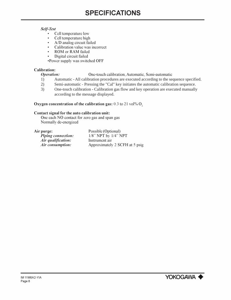
Self-Test Cell temperature low Cell temperature high A/D analog circuit failed Calibration value was incorrect ROM or RAM failed Digital circuit failedPower supply was switched OFF
Calibration:Operation: One-touch calibration, Automatic, Semi-automatic1) Automatic - All calibration procedures are executed according to the sequence specified.2) Semi-automatic - Pressing the "Cal" key initiates the automatic calibration sequence.3) One-touch calibration - Calibration gas flow and key operation are executed manually
according to the message displayed.
Oxygen concentration of the calibration gas: 0.3 to 21 vol% O2
Contact signal for the auto calibration unit:One each NO contact for zero gas and span gasNormally de-energized
Air purge: Possible (Optional)Piping connection: 1/8 NPT by 1/4 NPTAir qualification: Instrument airAir consumption: Approximately 2 SCFH at 5 psig
SPECIFICATIONS
IM 11M6A2-YIAPage 9
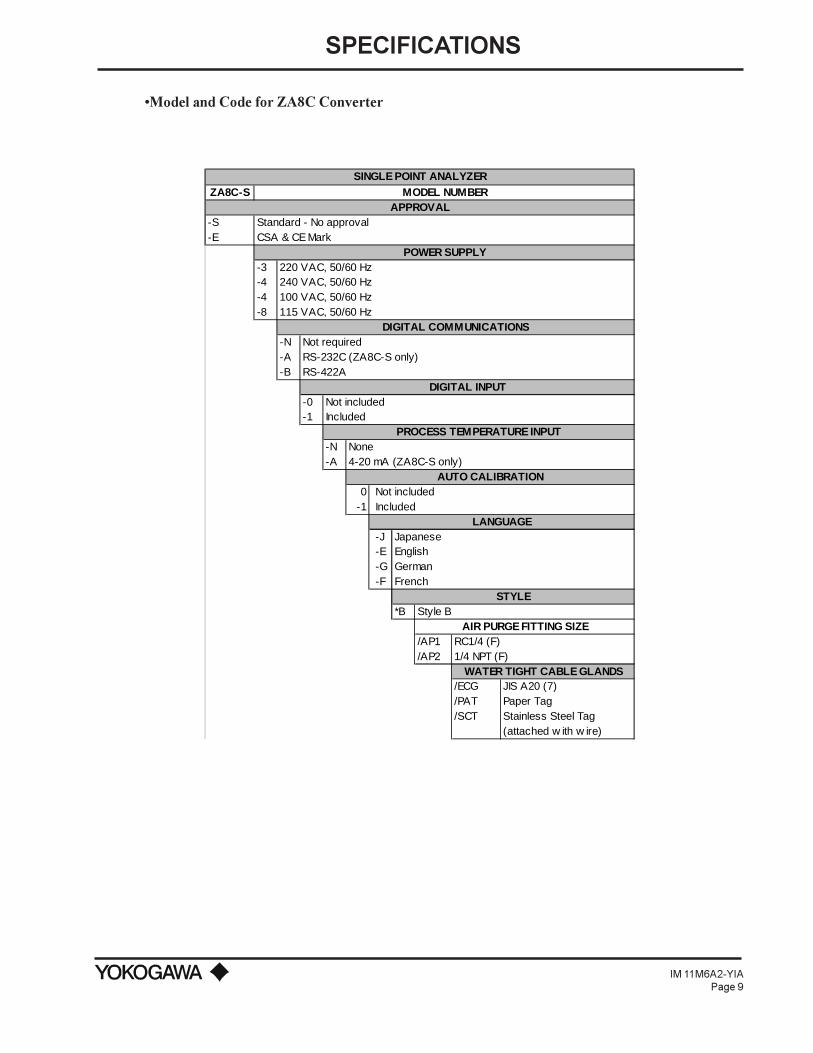
Model and Code for ZA8C Converter
SINGLE POINT ANALYZERZA8C-S MODEL NUMBER
APPROVAL-S Standard - No approval-E CSA & CE Mark
POWER SUPPLY-3 220 VAC, 50/60 Hz-4 240 VAC, 50/60 Hz-4 100 VAC, 50/60 Hz-8 115 VAC, 50/60 Hz
DIGITAL COMMUNICATIONS-N Not required-A RS-232C (ZA8C-S only)-B RS-422A
DIGITAL INPUT-0 Not included-1 Included
PROCESS TEMPERATURE INPUT-N None-A 4-20 mA (ZA8C-S only)
AUTO CALIBRATION0 Not included
-1 IncludedLANGUAGE
-J Japanese-E English-G German-F French
STYLE*B Style B
AIR PURGE FITTING SIZE/AP1 RC1/4 (F)/AP2 1/4 NPT (F)
WATER TIGHT CABLE GLANDS/ECG JIS A20 (7)/PAT Paper Tag/SCT Stainless Steel Tag
(attached w ith w ire)

SPECIFICATIONS
IM 11M6A2-YIAPage 10
2.2 MC1 MANUAL CALIBRATION PLATE
The MC1 is the manual calibration unit for a single oxygen probe. It provides flowrate regulation ofthe reference air and cal gas, allowing the operator to easily interface with ZA8C commands duringcalibration. Separate flowmeters are used to set cal gas and reference air flowrates.
•External Dimensions
Figure 3: Manual Calibration Unit

SPECIFICATIONS
IM 11M6A2-YIAPage 11
Standard Specifications
Flowrates: Cal gas - 0.6 LPM (1.3 SCFH); Reference air - 0.8 LPM (1.7SCFH)
NOTE: Exceeding recommended flowrates may damage the detector cell.
Maximum pressure: 35 psig
Cal plate: Stainless steel
Connection: 1/4 FNPT
Cal tubing: 1/4 copper (standard); 1/4 stainless steel (optional)
Weight: Approximately 4.4 lb (2 kg)
Ambient Temperature: 176ºF (80ºC) maximum
Model and Code for MC1 Cal Unit
SINGLE CHANNEL O2 MANUAL CALIBRATIONMC1 MODEL NUMBER
TUBING/FITTINGS-C 1/4" copper tubing and brass f ittings-S 1/4" stainless steel tubing and fittings
REFERENCE AIR FLOWMETER-R*U Reference air flow meter
2.3 AC1 SINGLE POINT AUTOMATIC CALIBRATION
The AC1 Automatic Calibration System is designed to work with the ZA8C Oxygen Converter toprovide accurate, automatic or semi-automatic calibration of the ZO21D oxygen detector. Thesolenoids of the AC1 are sequentially activated by internal contacts at the ZA8C converter.Calibration is achieved using instrument air and a compressed gas composed of oxygen balanced inNitrogen (typically 1%). The AC1 unit controls the flow of calibration gases and reference air.
To simplify operation of your O2 monitoring system, the AC1 comes fully assembled with plumbing,
flow control hardware, and solenoid wiring for calibrating the oxygen probe. All the User need provideis plumbing to the ZO21D probe and plumbing of the gases to the AC1, along with regulators andinterconnecting wiring between the AC1 and ZA8C. The AC1 requires 120 VAC.
The AC1 calibration unit is available with a choice of stainless steel fittings and tubing or brassfittings and copper tubing. Reference air flow control is a standard feature of the AC1, with separateflow indicators for cal gas and reference air. A clean, dry air source such as instrument air is used asboth span gas and reference air. The AC1 enclosure is available in NEMA 4 or 4X rating.
Initial setup of the auto calibration unit is simplified by the use of manual overrides for all solenoids.The overrides allow for a quick balancing of the calibration gas, without the use of power.

SPECIFICATIONS
IM 11M6A2-YIAPage 12
•EXTERNAL DIMENSIONS
Figure 4: Auto Calibration Unit
Figure 4 shows the mounting dimensions for the unit. It should be located in an accessible spot asclose to the oxygen probe as possible. Even though the enclosure is rated for NEMA 4 or 4X, it isadvisable to keep the unit out of direct rain. All external tubing should be 1/4” stainless steel orcopper. Connections to the unit are 1/4” FNPT.
•Standard Specifications
Operating pressure: up to 35 PSI
Maximum pressure: 50 PSI
Flowmeter range: 0.15 to 1 LPM (separate flowmeter for cal gas and reference air)
Flowrate: Cal Gas - 0.6 LPM; Reference Air - 0.8 LPM
Cal tubing: 1/4” copper (standard); 1/4” stainless steel (optional)
Gas connection: 1/4” FNPT
Voltage: 110 VAC, 50/60 Hz (standard)
Ambient Temperature: 176ºF (80ºC) maximum

SPECIFICATIONS
IM 11M6A2-YIAPage 13
Model and Code for AC1 Auto-Cal Unit
SINGLE CHANNEL O2 AUTO CALIBRATIONAC1 MODEL NUMBER
ENCLOSURE-4 NEMA 4, metal enclosure-5 NEMA 4X, f iberglass enclosure
TUBING/FITTINGS-C 1/4" copper tubing and brass fittings-S 1/4" stainless steel tubing and f ittings
REFERENCE AIR FLOWMETER-R*U Reference air flow meter

SPECIFICATIONS
IM 11M6A2-YIAPage 14
2.4 ZO21D-L STANDARD DETECTOR
The ZO21D-L general purpose low temperature detector is a direct insertion (in-situ) type oxygendetector used to continuously monitor the oxygen concentration of combustion gas. A zirconia cellmaintained by an internal heater at 1382ºF (750ºC) is the measuring sensor. Detector options include acheck valve, flame arrester (for FM approval), derakane coating and quick disconnect cabling.
External Dimensions
7.4
4.75
0.3
INLET-1/8 FNPT
1.7
CAL. GAS INLET-1/8 NPTF
WIRING HOLE 2-1.06 (27)
4.7
(188)(8)
(120
.7)
(120)
(42)
WITH RUBBER PLUG
7 8
654321
+ -HTR
CJ+ -
TC+ -
CELL+ -
GND
1.2 2.1(30) (53)
1.69(42.9)
0.5(12.7)WITH COVER REMOVED.
THIS VIEW SHOWN
CHECK VALVE
OPTIONAL FLAME ARRESTOR
(42.
4)
ø1.
67
ø6.1(155.0)
ON A ø5.0(127.0) BC4-ø0.45(11.5) HOLES
"L"
ON THE CAL. GAS INLET
8-ø0.75(19.1) HOLESON A ø7.5(190.5) BC
ø9.0(228.6)
ANSI CLASS 4", 150# FF FLANGE
ON A ø6.0(152.4) BC4-ø0.75(19.1) HOLES
ø7.5(190.5)
ANSI CLASS 3", 150# FF FLANGE
ø6.0(152.4)
ON A ø4.75(120.7) BC4-ô0.75(19.1) HOLES
ANSI CLASS 2", 150# FF FLANGE WESTINGHOUSE FLANGE
REFERENCE AIR
JIS FLANGE
Figure 5: Standard Detector
SPECIFICATIONS
IM 11M6A2-YIAPage 15
ZO21D WITH TRI-CLAMP FITTING
120
[4.7
]
5[0.2]
78.9
[?3.
11]
77.4
[3.0
5]
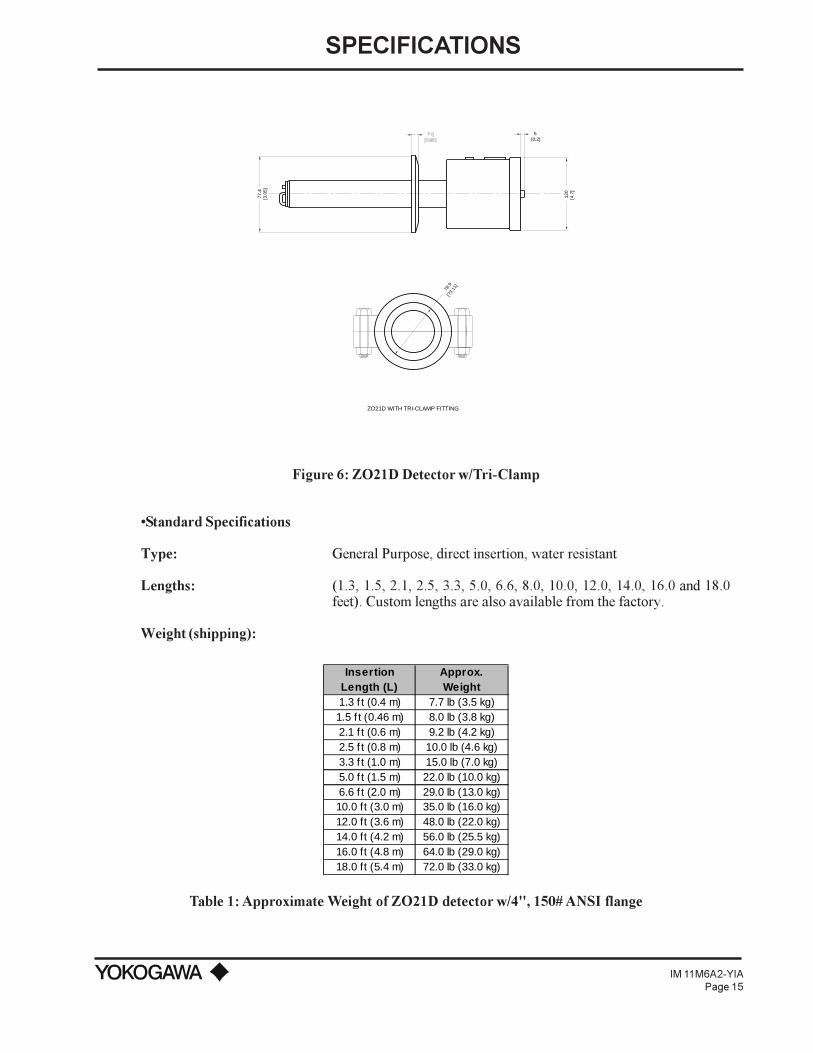
Figure 6: ZO21D Detector w/Tri-Clamp
Standard Specifications
Type: General Purpose, direct insertion, water resistant
Lengths: (1.3, 1.5, 2.1, 2.5, 3.3, 5.0, 6.6, 8.0, 10.0, 12.0, 14.0, 16.0 and 18.0feet). Custom lengths are also available from the factory.
Weight (shipping):
Insertion Length (L)
Approx. Weight
1.3 f t (0.4 m) 7.7 lb (3.5 kg)1.5 f t (0.46 m) 8.0 lb (3.8 kg)2.1 f t (0.6 m) 9.2 lb (4.2 kg)2.5 f t (0.8 m) 10.0 lb (4.6 kg)3.3 f t (1.0 m) 15.0 lb (7.0 kg)5.0 f t (1.5 m) 22.0 lb (10.0 kg)6.6 f t (2.0 m) 29.0 lb (13.0 kg)10.0 ft (3.0 m) 35.0 lb (16.0 kg)12.0 ft (3.6 m) 48.0 lb (22.0 kg)14.0 ft (4.2 m) 56.0 lb (25.5 kg)16.0 ft (4.8 m) 64.0 lb (29.0 kg)18.0 ft (5.4 m) 72.0 lb (33.0 kg)
Table 1: Approximate Weight of ZO21D detector w/4", 150# ANSI flange

SPECIFICATIONS
IM 11M6A2-YIAPage 16
Material: Terminal Box - 304SSProbe - 316SSProbe Flange - 304SSZirconium Oxide Sensor
Installation: Flange MountingFlange specs: 4” ANSI, Class 150# FF reduced bulk
3” ANSI, Class 150# FF reduced bulk2” ANSI, Class 150# FF reduced bulk2½" Tri-CloverWestinghouse flange
NOTE: Custom flanges are available upon request.
Mounting angle: The probe may be mounted vertically with cell end down or any angleto horizontal. A probe support (or protector) is required for allprobes longer than two meters.
Reference air andCalibration gas inlets: 1/8 NPT female
Cable inlet: 27 mm (2 locations)
Ambient temperature: 14º to 176ºF (-10º to 80ºC)
Sample temperature: 0º to 1230ºF (0º to 700ºC)
Sample gas pressure: ±0.7 psig (±500 mm H2O)

SPECIFICATIONS
IM 11M6A2-YIAPage 17
Model and Code
LOW TEMPERATURE DETECTORZO21D-L General PurposeZO21D-E CE Mark
INSERTION LENGTH 1
-040 0.40 m (1.3’, 15.6")-046 0.46 m (1.5’, 18") ZO21D-L only-064 0.64 m (2.1’, 25") ZO21D-L only-076 0.76 m (2.5’, 30") ZO21D-L only-100 1.0 m (3.3’)-150 1.5 m (5.0’)-200 2.0 m (6.6’)-245 2.45 m (8.0’) ZO21D-L only-300 3.0 m (10.0’)-360 3.6 m (12.0’) These detector lengths ZO21D-L only-420 4.2 m (14.0’) These detector lengths ZO21D-L only-480 4.8 m (16.0’) These detector lengths ZO21D-L only-540 5.4 m (18.0’) ZO21D-L only
FLANGE MOUNTING 3, 6
-A*U ANSI 4", 150# FF flange 5
-B*U ANSI 3", 150# FF flange ZO21D-L only-C*U ANSI 2", 150# FF flange ZO21D-L only-J*U JIS 5K, 65A FF f lange-T*U 2½" Tri-clamp flange ZO21D-L only-W*U Westinghouse flange ZO21D-L only
OPTIONS (can select more than one)/A Quick disconnects (male portion)/C Check Valve (M1132KN)/D Derakane coating 4
/F Flame arrester 2/PAT Paper Tag (attached w ith w ire)/SCT Stainless Steel Tag (attached w ith w ire)/T Welded NPT Collar w ithout Flame arrester
NOTES:1) For special Detector lengths and flanges contact Yokogaw a Corporation of America.2) The Filter Assemblies (E7042UQ and M1100DA or DA-2) are not compatible w ith, nor required w hen the flame arrester option is selected. The f lame arrester includes its ow n f ilter. Replacement part number for f lame arrester filter is E7042VG. Filter assemblies and/or f lame arrester option w ill not fit through a 2", ANSI mounting f lange (-C*U) or 2½" Tri-clamp (-T*U).3) The (*U) portion of the part number indicates that the detector is made in the United States at Yokogaw a Corporation of America, New nan, Georgia.4) Derakane coating is recommended for any application up to 390° F (200º C) w here elements corrosive to the detector may be present, such as those found in chemical incinerators.5) The 4" ANSI Flange (-A*U) is suggested for probe lengths 2 m or greater. 6) Detector lengths greater than 10.0 ft (3.0 m) use a RF f lange instead of a FF flange. 7) Only available w ith -040 and -100 lengths.

SPECIFICATIONS
IM 11M6A2-YIAPage 18
2.5 ZO21D-H HIGH TEMPERATURE DETECTOR WITH ZO21P-H ADAPTER
The high temperature detector is a general purpose probe utilized in conjunction with a hightemperature adapter tee (ZO21P) in applications with temperatures ranging between 1200ºF and3400ºF . The detector is mounted to an adapter reducing the heat of the process gas throughconduction. Probe options include derakane coating, flame arrester (for FM approval), and quickdisconnect wiring.
External Dimensions
FLANGE
(WITH RUBBER PLUG)
2-ø1.06 (ø27) WIRING HOLES
CALIBRATION GAS INLET
(38)
1/8 FNPT
ø1.7[43.2]
4-ø0.63(ø16.0) HOLESON A 3.54 (89.9) DIABOLT CIRCLE
ø4.
50
(ø11
4.3)
2.1
(53)
1.5
1.7
(43)
ø1.
7
(ø43
)(150)
0.2
(5)
4.7
(120
)
0.31
(8)
THIS VIEW SHOWN
WITH COVER REMOVED.
GND
TCCELL
+
1
-
2
+
3
HTR
+
7
CJ
-
8
-
4
+
5
-
6
(168)
5.9 6.6
REFERENCE AIR INLET
1/8 FNPT
Figure 7: ZO21D-H-015-K-UHigh Temperature detector with 150# JIS flange and junction box

SPECIFICATIONS
IM 11M6A2-YIAPage 19
ANSI 3" 150LB FF
FLANGE
(WITH RUBBER PLUG)
2-ø1.06 (ø27) WIRING HOLES
CALIBRATION GAS INLET
(38)
1/8 FNPT
FLAME ARRESTOR
ø1.7[43.2]
4-ø0.75 (ø19.1) HOLESON A ø6.00 (152.4)DIABOLT CIRCLE
ø7.
50
(ø19
0.5)
2.1
(53)
1.5
1.7
(43)
ø1.
7
(ø43
)
0.2
(5)0.38
(9.5)
4.7
(120
)
1.0(25.4)
THIS VIEW SHOWN
WITH COVER REMOVED.
GND
TCCELL
+
1
-
2
+
3
HTR
+
7
CJ
-
8
-
4
+
5
-
6
(ø60
)
ø2.
38
7.13(181)
3.25
MA
X.
(83
MA
X.)
(173)
6.8 6.6
(168)
REFERENCE AIR INLET
1/8 FNPT
Figure 8: ZO21D-H-017-L*U/FHigh Temperature Detector with Junction Box and flange
Standard Specifications
Type: General Purpose, Water-vapor Resistant
Material: Terminal Box- 304SSProbe - 316SSFlange - 304SS
Zirconium Oxide Sensor
Weight: 7 lbs (3.2 kgs); /F option - add 8 lbs (3.6 kgs)
Installation: Flange mounting with the high temperature probe adapter any anglefrom vertical to horizontal.
Reference air andCalibration gas inlet: 1/8 NPT female fittings
Cable inlet: Two holes of 27 mm

SPECIFICATIONS
IM 11M6A2-YIAPage 20
Ambient Temperature: 14º to 302ºF (-10º to 150ºC)
Sample Gas Temp: 32º to 1230ºF (0º to 700ºC) when no adapter is used and 32º to3600ºF (0º to 1400ºC) when probe adapter is used.
Sample Gas Pressure: ±0.7 psi (±500 mm H2O)
Optional Quick Disconnects: (Refer to sections 2.7.6 and 2.7.7)
Model and Code
HIGH TEMPERATURE DETECTORMODEL NUMBER DESCRIPTIONZO21D-H-015-K*U High temperature detector includes a JIS5K32A f langeZO21D-H-017-K*U High temperature detector for flame arrester
Includes a 3" ANSI f lange 1
ZO21D-F-015-K*U CE MarkOPTIONS (can select more than one)
/A Quick disconnects (male portion) (not available on ZO21D-F)/C Check Valve (M1132KF)/D Derakane coating 2
/F Flame arrester (ZO21D-H-017 only) 1
/SCT Stainless Steel Tag (attached w ith w ire)/PAT Paper Tag (attached w ith w ire)/T Welded NPT Collar w ithout Flame Arrester 1
NOTES:1) /F VERSION - Order ZO21D-H-017-L*U/F for probe w ith preattached f lame arrester. Probe adapter ZO21P-F is used w ith flame arrester option. /T on a probe includes the mounting threads w ithout the f lame arrester. DO NOT SPECIFY /T/F.2) /D DERAKANE COATING - Used for corrosive applications. Cannot be used if the tee temperature is maintained above 390º F (200º C).
2.5.1 ZO21P Adapter for the High Temperature ProbeThe probe adapter is used to reduce the sample gas temperature below 1230ºF (700ºC) before it ismeasured by the detector. The adapter tee cools the process gas through conduction, preventingoverheating of the cell. A transport tube and eductor assembly provide the extraction of the processgas in negative pressure applications. A heated eductor option helps prevent condensation fromforming in the ejector assembly. See Table 2 for the transport tube material and insertion lengths. Inapplications prone to blockage, an optional manual Blow Back system is used. Instrument air isblown through the transport tube, removing possible obstructions. Refer to IM 11M6Z2-YIA fordetails regarding the "Blow Back" system.

SPECIFICATIONS
IM 11M6A2-YIAPage 21
External Dimensions
1/4 FNPT
(Ø6
0) 4 - ø0.63(ø16.0) HOLES
ON A 3.54 (89.9) DIABOLT CIRCLE
3/4 FNPT6.1
9.71
1.7
NOTES:1. MATERIAL IS 316 SST, EXCEPT FOR ANSIFLANGE WHICH IS 304 SST.
2. WEIGHT: 24.3 LBS(11 Kg)
(ø114.3)0.38(9.7) THK FLANGE
(193)
(ø22
8.6)
8 - ø0.75(4819.1) HOLESON A 7.50(190.5)DIABOLT CIRCLE0.94(23.8) THK FLANGE4" ANSI 150#RAISED FACE FLANGE
(297)
(246)
Ø2
.4
(155)
(2 PLACES)
[1.0
m]
7.60
ø9.
00
3.3F
T
ø4.50
Figure 9: ZO21P-HHigh Temperature Adapter Tee
11.8
(301
)
9.1
(232
)
ø4.
5
(ø11
4)
5.7
(145
)
1/4 FNPT4 - ø0.75(ø19.1) HOLESON A 6.00(152.4) DIABOLT CIRCLE
ø7.5
(ø191)0.38 (9.7) THK FLANGE
10.4
(265)
3/4 FNPT
ø9.
0
(ø22
8.6)
8 - ø0.75(ø19) HOLESø7.50[ 190.5] BOLT CIRCLE0.94(23.8) THK FLANGE
4" ANSI 150#RAISED FACE FLANGE
3" ANSI 150#RAISED FACE FLANGE[1
.0m
]
3.3F
T
ø0.8[ø20]
ø1.9
(ø48)
2.5
(64)
Figure 10: ZO21P-FHigh Temperature Adapter for the Flame Arrester
SPECIFICATIONS
IM 11M6A2-YIAPage 22
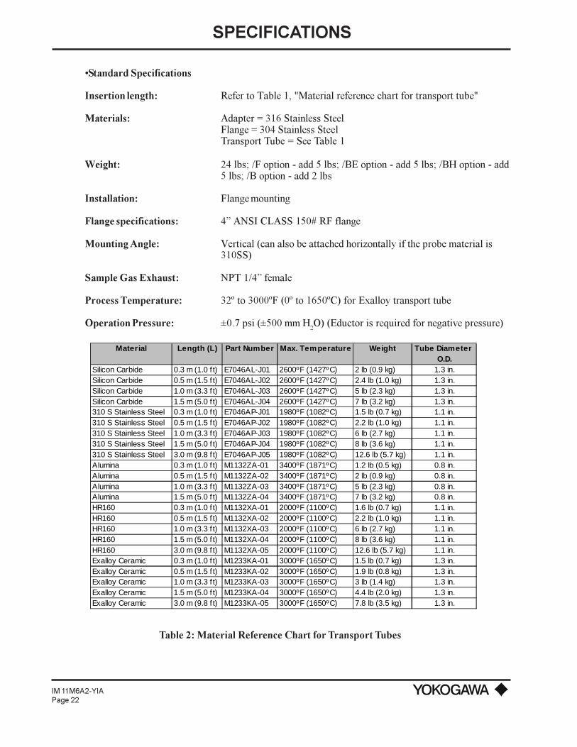
Standard Specifications
Insertion length: Refer to Table 1, "Material reference chart for transport tube"
Materials: Adapter = 316 Stainless SteelFlange = 304 Stainless SteelTransport Tube = See Table 1
Weight: 24 lbs; /F option - add 5 lbs; /BE option - add 5 lbs; /BH option - add5 lbs; /B option - add 2 lbs
Installation: Flange mounting
Flange specifications: 4 ANSI CLASS 150# RF flange
Mounting Angle: Vertical (can also be attached horizontally if the probe material is310SS)
Sample Gas Exhaust: NPT 1/4 female
Process Temperature: 32º to 3000ºF (0º to 1650ºC) for Exalloy transport tube
Operation Pressure: ±0.7 psi (±500 mm H2O) (Eductor is required for negative pressure)
Table 2: Material Reference Chart for Transport Tubes
Material Length (L) Part Number Max. Temperature Weight Tube Diameter O.D.
Silicon Carbide 0.3 m (1.0 f t) E7046AL-J01 2600ºF (1427ºC) 2 lb (0.9 kg) 1.3 in.Silicon Carbide 0.5 m (1.5 f t) E7046AL-J02 2600ºF (1427ºC) 2.4 lb (1.0 kg) 1.3 in.Silicon Carbide 1.0 m (3.3 f t) E7046AL-J03 2600ºF (1427ºC) 5 lb (2.3 kg) 1.3 in.Silicon Carbide 1.5 m (5.0 f t) E7046AL-J04 2600ºF (1427ºC) 7 lb (3.2 kg) 1.3 in.310 S Stainless Steel 0.3 m (1.0 f t) E7046AP-J01 1980ºF (1082ºC) 1.5 lb (0.7 kg) 1.1 in.310 S Stainless Steel 0.5 m (1.5 f t) E7046AP-J02 1980ºF (1082ºC) 2.2 lb (1.0 kg) 1.1 in.310 S Stainless Steel 1.0 m (3.3 f t) E7046AP-J03 1980ºF (1082ºC) 6 lb (2.7 kg) 1.1 in.310 S Stainless Steel 1.5 m (5.0 f t) E7046AP-J04 1980ºF (1082ºC) 8 lb (3.6 kg) 1.1 in.310 S Stainless Steel 3.0 m (9.8 f t) E7046AP-J05 1980ºF (1082ºC) 12.6 lb (5.7 kg) 1.1 in.Alumina 0.3 m (1.0 f t) M1132ZA-01 3400ºF (1871ºC) 1.2 lb (0.5 kg) 0.8 in.Alumina 0.5 m (1.5 f t) M1132ZA-02 3400ºF (1871ºC) 2 lb (0.9 kg) 0.8 in.Alumina 1.0 m (3.3 f t) M1132ZA-03 3400ºF (1871ºC) 5 lb (2.3 kg) 0.8 in.Alumina 1.5 m (5.0 f t) M1132ZA-04 3400ºF (1871ºC) 7 lb (3.2 kg) 0.8 in.HR160 0.3 m (1.0 f t) M1132XA-01 2000ºF (1100ºC) 1.6 lb (0.7 kg) 1.1 in.HR160 0.5 m (1.5 f t) M1132XA-02 2000ºF (1100ºC) 2.2 lb (1.0 kg) 1.1 in.HR160 1.0 m (3.3 f t) M1132XA-03 2000ºF (1100ºC) 6 lb (2.7 kg) 1.1 in.HR160 1.5 m (5.0 f t) M1132XA-04 2000ºF (1100ºC) 8 lb (3.6 kg) 1.1 in.HR160 3.0 m (9.8 f t) M1132XA-05 2000ºF (1100ºC) 12.6 lb (5.7 kg) 1.1 in.Exalloy Ceramic 0.3 m (1.0 f t) M1233KA-01 3000ºF (1650ºC) 1.5 lb (0.7 kg) 1.3 in.Exalloy Ceramic 0.5 m (1.5 f t) M1233KA-02 3000ºF (1650ºC) 1.9 lb (0.8 kg) 1.3 in.Exalloy Ceramic 1.0 m (3.3 f t) M1233KA-03 3000ºF (1650ºC) 3 lb (1.4 kg) 1.3 in.Exalloy Ceramic 1.5 m (5.0 f t) M1233KA-04 3000ºF (1650ºC) 4.4 lb (2.0 kg) 1.3 in.Exalloy Ceramic 3.0 m (9.8 f t) M1233KA-05 3000ºF (1650ºC) 7.8 lb (3.5 kg) 1.3 in.

SPECIFICATIONS
IM 11M6A2-YIAPage 23
Model and Code
HIGH TEMPERATURE PROBE ADAPTERZO21P MODEL NUMBER
TEE CONFIGURATION 1
-H Basic design (side eductor port)-T Basic design (bottom port)-S Split design (for blow back)-F Oversized design (for f lame arrester, includes studs)-C All Hastelloy C (conf igured as -T only)
TRANSPORT TUBE MATERIAL-A Silicon Carbide (SiC) (Up to 2600ºF/1427ºC)-B 310 Stainless Steel (Up to 1980ºF/1082ºC)-C Alumina Ceramic (Up to 3400ºF/1871ºC)-H HR160 Stainless Steel (Up to 2000ºF/1100ºC)-X Exalloy Ceramic (Up to 3000ºF/1650ºC)-N NO TRANSPORT TUBE
INSERTION LENGTH-033 0.3 m (13")-050 0.5 m (20")-100 1.0 m (3.3')-150 1.5 m (5.0')-300 3.0 m (9.8') (not for -A or -C tubes)-NNN NO TRANSPORT TUBE
FLANGE CONNECTION-A*U ANSI 4", 150# RF
OPTIONS(m ay select one from each group)
Options Heater System/HT Aux heater system (to 600º F)
[includes controller and heaters]Blow back Block Valve (for ZO21P-S)
/AV Automatic valve/MV Manual valve
Eductor/BE Wrapped air eductor pre-attached w ith
regulator and gauge (for ZO21P-H w ithout /HT only)/ER Air ejector w /return exhaust pre-
attached w ith regulator and gauge (for ZO21P-H or ZO21P-S only)
/SE Separate air ejector, regulator and gauge (not preattached)
/WE Self-cleaning w ater ejector (regulator and gauge not included)
/E4 Tag/SCT Stainless Steel Tag (attached w ith w ire)/PAT Paper Tag (attached w ith w ire)
NOTES:1) The -H option is the standard tee. T-eductor port is mounted on the side - (180º f rom the probe.) -S i designed for applications that require blow back to keep the transport tube clean. It must have a valv installed (1" NPT, full port, high temp). Customer must specify option /MV or /AV. -F is an oversized tee for applications requiring a f lamer arrester.

SPECIFICATIONS
IM 11M6A2-YIAPage 24
2.5.2 Temperature Controller (/HT)Controller is installed in NEMA 4X enclosure, and is preconfigured with a setpoint value of 600ºFwith 700ºF alarm.
Standard Specifications
Supply Voltage: 85 to 264 VAC; 50/60 Hz; Rating: 100 to 240 VAC
Thermocouple: Type J included, preset @ 600ºF (316ºC) setpoint
Power Consumption: Less than 17 VA for standard AC type.
Operating environment: 30º to 122ºF (0º to 50ºC); 45 to 85% RH
Control: Preset for PD control.
Alarm: Heater break alarm preset at 700ºF (371ºF)
Net Weight: 6 oz (0.17 kg)
Certification: UL recognized; CSA listing.
2.5.3 Water Eductor (option /WE )Used as the pumping mechanism for obtaining a sample from the process, water is used to create avacuum, thereby directing the sample through the adapter tee.
Standard Specifications
Water Pressure: 20 PSI minimumWater Consumption: 2.5 GPMWater Vacuum Flow: .56 GPMAir Vacuum Flow: .08 SCFMVacuum Force: 29" HgMaterial: Anodized AluminumWeight: 6 oz
1/4" MNPT
P/N M1133CW
MOUNTING PLATE
WATER SUPPL1/8" FNPT
1/8" FNPT
Figure 11: Water Eductor Ejector Assembly
SPECIFICATIONS
IM 11M6A2-YIAPage 25
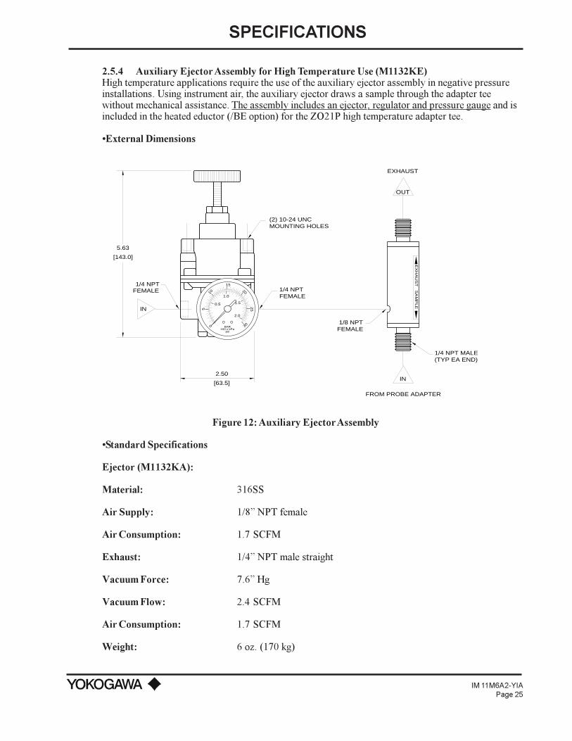
2.5.4 Auxiliary Ejector Assembly for High Temperature Use (M1132KE)High temperature applications require the use of the auxiliary ejector assembly in negative pressureinstallations. Using instrument air, the auxiliary ejector draws a sample through the adapter teewithout mechanical assistance. The assembly includes an ejector, regulator and pressure gauge and isincluded in the heated eductor (/BE option) for the ZO21P high temperature adapter tee.
External Dimensions
0 3025
20
15
10
5
BAR100 x kPa
psi
0.5
1.0
1.5
2.0
2.50
[63.5]
5.63
[143.0]
IN
IN
FROM PROBE ADAPTER
1/4 NPTFEMALE 1/4 NPT
FEMALE
1/8 NPTFEMALE
(2) 10-24 UNCMOUNTING HOLES
OUT
EXHAUST
1/4 NPT MALE(TYP EA END)
EX
HA
US
TS
AM
PLE
Figure 12: Auxiliary Ejector Assembly
Standard Specifications
Ejector (M1132KA):
Material: 316SS
Air Supply: 1/8 NPT female
Air Consumption: 1.7 SCFM
Exhaust: 1/4 NPT male straight
Vacuum Force: 7.6 Hg
Vacuum Flow: 2.4 SCFM
Air Consumption: 1.7 SCFM
Weight: 6 oz. (170 kg)
SPECIFICATIONS
IM 11M6A2-YIAPage 26
Vacuum: 1/4 NPT male
Connection to high-tempprobe adapter: 1/4 NPT
Piping Connection: 1/4 NPT female
Connection tube: 1/4 stainless pipe
Pressure Gauge (M1132CG):
Indicates the pressure of instrument air flowing into the eductor.
Gauge Size: 2
Measuring Range: 0 to 60 psi
Piping Connection: 1/4 NPT male
Scaling: 0 to 30 psig (0 to 2 bar)
Ambient Temperature: 140ºF (40ºC) at maximum
Pressure Regulator (M1132KD):
This general purpose regulator is used to adjust the flow of instrument air entering the ejector. Madeof durable materials and corrosion resistant construction, it provides reliable operation in harshindustrial environments.
Flow Capacity: 20 SCFM (33.6 m3/hr) at 100 psig(700 kPa) supply - 20 psig (140 kPa) outlet.
Exhaust Capacity: 0.1 SCFM (0.17 m3/hr) - downstream pressure 5 psig (35 kPa) abovesetpoint.
Sensitivity: 1 H2O (25.4 mm)
Effect of SupplyPressure variation: Less than 0.2 psig (1.4 kPa) for 25 psi (170 kPa) change
Maximum Supply Pressure: 250 psig (1700 kPa)
Air Consumption: Less than 6 SCFH (0.17 m3/hr)
Output Range: 0 to 60 psi (0-400 kPa)
Port Size: 1/4 NPT
Materials: Body - Die cast aluminum alloy; Diaphragm - Nitrile elastomer andnylon fabric; Trim - Brass, zinc plated steel, acetal.
Weight: 4.0 lbs (1.8 kgs)
SPECIFICATIONS
IM 11M6A2-YIAPage 27
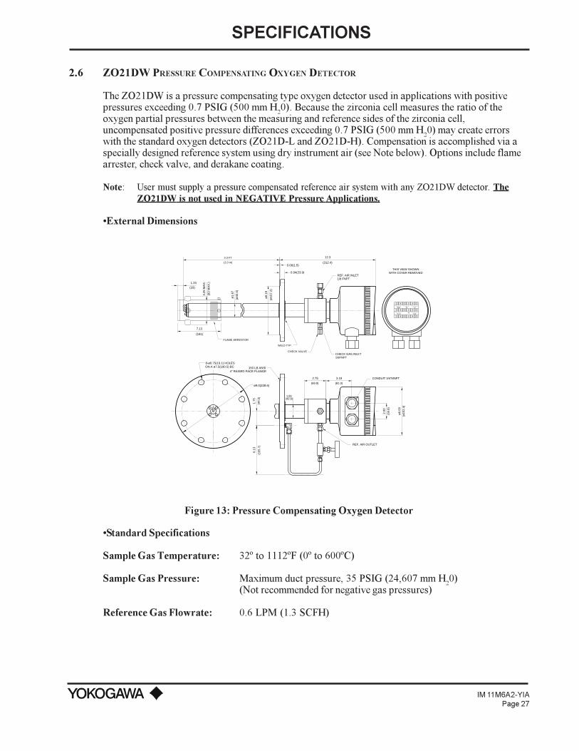
2.6 ZO21DW PRESSURE COMPENSATING OXYGEN DETECTOR
The ZO21DW is a pressure compensating type oxygen detector used in applications with positivepressures exceeding 0.7 PSIG (500 mm H20). Because the zirconia cell measures the ratio of theoxygen partial pressures between the measuring and reference sides of the zirconia cell,uncompensated positive pressure differences exceeding 0.7 PSIG (500 mm H20) may create errorswith the standard oxygen detectors (ZO21D-L and ZO21D-H). Compensation is accomplished via aspecially designed reference system using dry instrument air (see Note below). Options include flamearrester, check valve, and derakane coating.
Note: User must supply a pressure compensated reference air system with any ZO21DW detector. TheZO21DW is not used in NEGATIVE Pressure Applications.
External Dimensions
1.69(42.9)
4" RAISED FACE FLANGE
ø6.
19
150 LB ANSI
0.94(23.9)
0.06(1.5)
3.3 FT
ø9.0(228.6)
ON A ø7.5(190.5) BC 8-ø0.75(19.1) HOLES
CHECK VALVE
FLAME ARRESTOR
(ø42
.4)
ø1.
67
WELD TYP.
+
+
TC
TC-IN
-
-
CELL+
HTR
+-
+
CJ-
-
12.3
(312.4)
THIS VIEW SHOWN WITH COVER REMOVED
ø6.
00(ø
152.
4)
2.00
(50.
8)
2.75 3.19
(69.9) (81.0)
1.75
(44.
5)
6.13
(155
.7)
REF. AIR INLET1/8 FNPT
CHECK GAS INLET1/8FNPT
REF. AIR OUTLET
CONDUIT 3/4"MNPT
(ø15
7.2)
(1.0 m)
3.25
MA
X.
(83
MA
X.)
7.13
(181)
1.33
(33)
Figure 13: Pressure Compensating Oxygen Detector
Standard Specifications
Sample Gas Temperature: 32º to 1112ºF (0º to 600ºC)
Sample Gas Pressure: Maximum duct pressure, 35 PSIG (24,607 mm H20)(Not recommended for negative gas pressures)
Reference Gas Flowrate: 0.6 LPM (1.3 SCFH)

SPECIFICATIONS
IM 11M6A2-YIAPage 28
Insertion Length and Weight:
Length (L) Weight1.3 ft (0.4 m) 14 lb (6.5 kg)3.3 ft (1.0 m) 22 lb (10 kg)5.0 ft (1.5 m) 29 lb (13 kg)6.6 ft (2.0 m) 37 lb (17 kg)10 ft (3.0 m) 44 lb (20 kg)12 ft (3.6 m) 52 lb (23.5 kg)
Table 3: Probe lengths and weights for ZO21DW
Ambient Temperature: 14º to 176ºF (-10º to 80ºC)
Material in Contact with Gas: Terminal box: Aluminum casting; probe: 316SS; flange: 304SS;sensor: Zirconia
Construction: Water-resistant, direct insertion
Installation: Flange Mounted, ANSI Class 4, 150# RF Flange
Flange Connection: 1/8 FNPT Fitting with NPSM 3/4 Conduit Fitting.
Probe Mounting Angle: Vertically with cell end down or horizontally, or at an angle inbetween. When probe length is greater than 2.0 m, use a probesupport or probe protector (see Accessories).
Wiring: For description, refer to Accessories.
Model and Code
PRESSURE COMPENSATING (Low Temperature)ZO21DW-L MODEL NUMBER
INSERTION LENGTH 1
-040 0.40 m (1.3’, 15.6")-100 1.0 m (3.3’)-150 1.5 m (5.0’)-200 2.0 m (6.6’)-300 3.0 m (10.0’) These detector lengths require a probe -360 3.6 m (12.0’) support or probe protector.
FLANGE CONNECTION-A*A ANSI 4", 150# RF flange
FLANGE CONNECTION-NPT 1/8" FNPT fitting w ith NPSM 3/4" conduit fitting
OPTIONS (can select more than one)/C Check Valve (required)/D Derakane coating 1
/F Flame Arrestor/SCT Stainless Steel Tag (attached w ith w ire)/PAT Paper Tag (attached w ith w ire)/T Welded NPT Collar w ithout f lame arrester
NOTES:1) Derakane coating is recommended for applications up to 390º F (200º C) w here elements corrosive to the detector may be present. Such as those found in chemical incinerators.
SPECIFICATIONS
IM 11M6A2-YIAPage 29
2.6.1 ZO21DW Reference Air System, Model ZA8RThe model ZA8R is a dual calibration unit that in addition to performing automatic calibration, alsoprovides pressure compensation for the model ZO21DW pressure compensating detector. Optionally,instrument air may be used to provide Safety Blowback. Consult factory for more detailedinformation.
Standard Specifications
Calibration Air: Clean dry instrument grade air
Flowmeter Range: 0.15 to 1 LPM
Flowrate: Cal Gas - 0.6 LPM (1.3 SCFH)Reference Air - 0.8 LMP (1.7 SCFH)
Operating Pressure: Pressure setting for Cal Gas and Reference Air is approximately 14PSIG above wind box pressure.
Maximum pressure: 35 PSIG
Operating pressure: 0.7 to 35 PSIG
Gas connection: 1/4 FNPT
Voltage: 110 VAC, 50/60 Hz (standard)220 VAC, 50/60 Hz (optional)
Ambient Temperature: 14º to 176ºF (-10º to 80ºC)
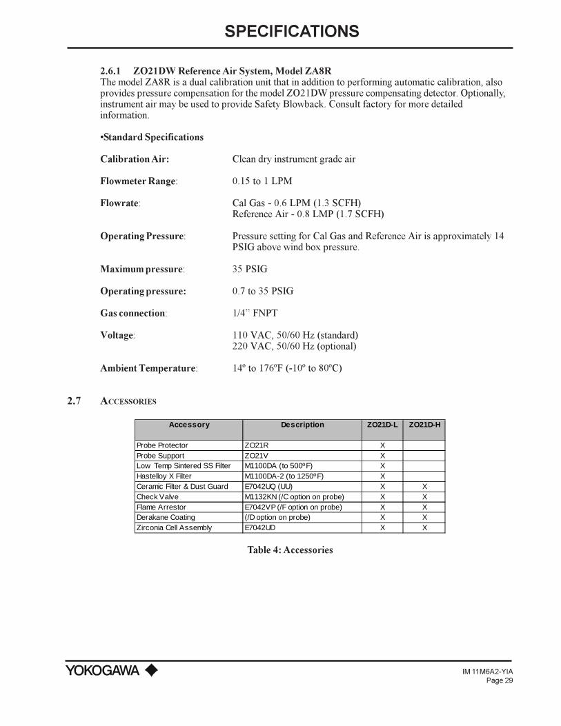
2.7 ACCESSORIES
Accessory Description ZO21D-L ZO21D-H
Probe Protector ZO21R XProbe Support ZO21V XLow Temp Sintered SS Filter M1100DA (to 500ºF) XHastelloy X Filter M1100DA-2 (to 1250ºF) XCeramic Filter & Dust Guard E7042UQ (UU) X XCheck Valve M1132KN (/C option on probe) X XFlame Arrestor E7042VP (/F option on probe) X XDerakane Coating (/D option on probe) X XZirconia Cell Assembly E7042UD X X
Table 4: Accessories

SPECIFICATIONS
IM 11M6A2-YIAPage 30
2.7.1 ZO21R Probe ProtectorA probe protector is required for most coal fired boilers, lime kilns, cement kilns and incineratorswhere the abrasive particles in the flue gas may erode the wall of the oxygen detector. Probe protectorsmay only be used in conjunction with the ZO21D-L.
External Dimensions
Detector
PROBE PROTECTOR316 SS
3.3 ID
(83.82)
"A"
"B"
FLY ASH FILTER
4.0
(101
.6)
ANSI CLASS 2", 150# FF FLANGE
4-ô0.75(19.1) HOLESON A ø4.75(120.7) BC
ø6.0(152.4)
JIS FLANGE
WESTINGHOUSE FLANGE
ø6.1(155.0)
4-ø0.45(11.5) HOLESON A ø5.0(127.0) BC
0.70(17.8) W/ ø1.38(35.1)
ANSI 4" 150 LB FLANGE
4-ø0.75(19.1) HOLES EVENLY SPACEDON A ø7.5(190.5) BC
ON A ø7.5(190.5) BC
4-ø0.75(19.1) HOLES COUNTER SUNK
ø9.0(228.6)
ANSI CLASS 3", 150# FF FLANGE
ø7.5(190.5)
4-ø0.75(19.1) HOLESON A ø6.0(152.4) BC
Figure 14: Probe Protector
NOTE: When probe is longer than 10 feet, clamps are used to center the probe.
Standard Specifications
Material: 316SS Pipe304SS, ANSI 4 150# flange
Installation: Flange Mount (FF type)
Length/Weight:
For custom lengths, please contact your local Yokogawa Industrial Automation representative.

SPECIFICATIONS
IM 11M6A2-YIAPage 31
Insertion Length (L)
Approx. Weight
1.3 ft (0.4 m) 15 lb (7 kg)1.5 f t (0.46 m) 18 lb (8.2 kg)2.1 f t (0.64 m) 20 lb (9.1 kg)2.5 f t (0.76 m) 21 lb (9.5 kg)3.3 ft (1.0 m) 22 lb (10 kg)5.0 ft (1.5 m) 29 lb (13 kg)6.6 ft (2.0 m) 35 lb (16 kg)10.0 f t (3.0 m) 48.5 lb (22 kg)
Table 5: Approximate Length and Weight of ZO21R-L probe protector w/4", 150# ANSI flange
Model and Code
LOW TEMPERATURE PROBE PROTECTORZO21R-L MODEL NUMBER
INSERTION LENGTH-040 0.40 m (1.3’, 15.6")-046 0.46 m (1.5’, 18")-064 0.64 m (2.1’, 25")-076 0.76 m (2.5’, 30")-100 1.0 m (3.3’)-150 1.5 m (5.0’)-200 2.0 m (6.6’)-300 3.0 m (10.0’)
FLANGE CONNECTION-A*U ANSI 4", 150# FF flange -B*U ANSI 3", 150# FF flange-C*U ANSI 2", 150# FF flange-J*U JIS 5K, 65AFF Flange-W*U Westinghouse f lange
SPECIFICATIONS
IM 11M6A2-YIAPage 32
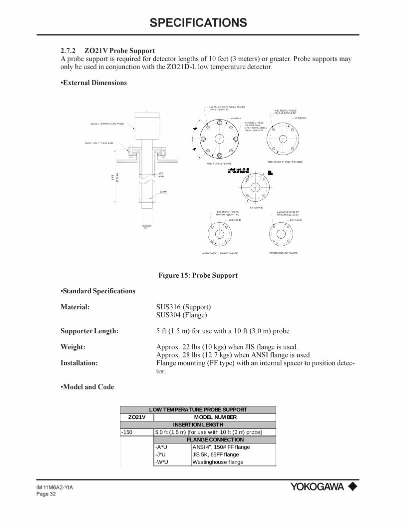
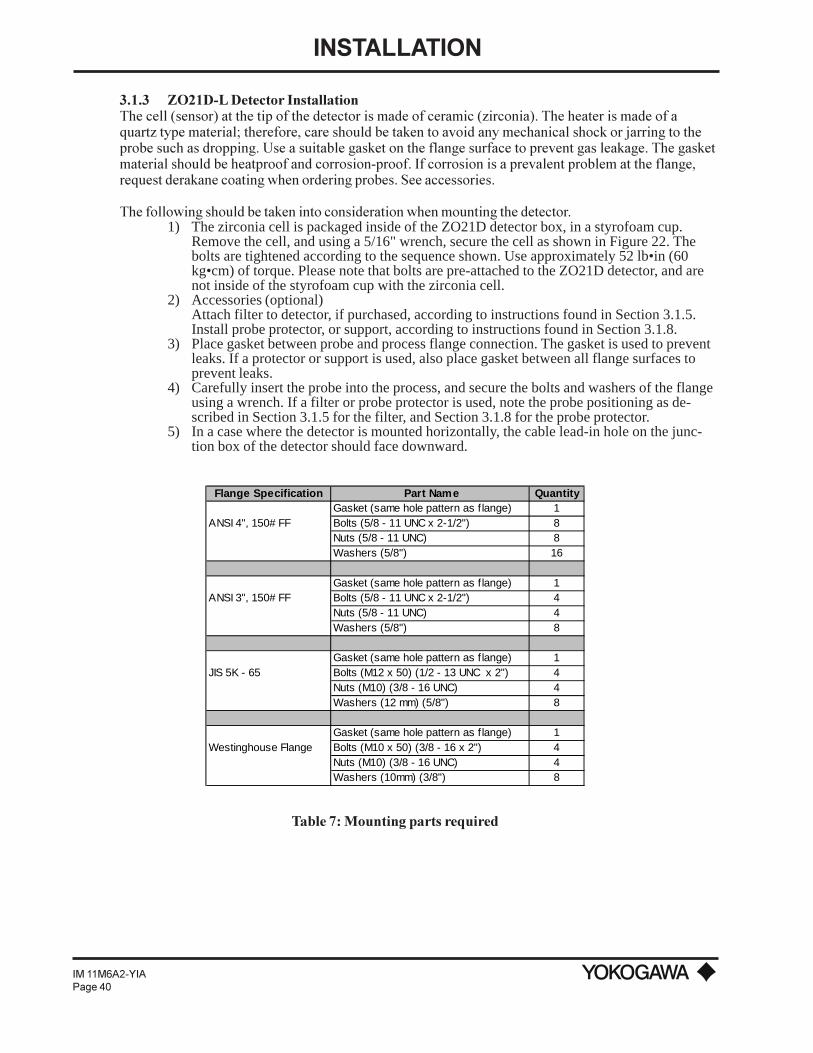
2.7.2 ZO21V Probe SupportA probe support is required for detector lengths of 10 feet (3 meters) or greater. Probe supports mayonly be used in conjunction with the ZO21D-L low temperature detector.
External Dimensions
CLAMP
(1.5
m)
5 F
T (ø89)
ANSI 4" 150#, 1" THK FLANGE
ZO21D-L TERMPERATURE PROBE
ø3.5
ANSI 4" 150 LB FLANGE
ø9.0(228.6)
4-ø0.75(19.1) HOLES EVENLY SPACEDON A ø7.5(190.5) BC
COUNTER SUNK4-ø0.75(19.1) HOLES
ON A ø7.5(190.5) BC 0.70(17.8) W/ ø1.38(35.1)
ø6.1(155.0)
ON A ø5.0(127.0) BC4-ø0.45(11.5) HOLES
ON A ø6.0(152.4) BC4-ø0.75(19.1) HOLES
ø7.5(190.5)
ANSI CLASS 3", 150# FF FLANGE
ø6.0(152.4)
ON A ø4.75(120.7) BC4-ô0.75(19.1) HOLES
ANSI CLASS 2", 150# FF FLANGE WESTINGHOUSE FLANGE
JIS FLANGE
Figure 15: Probe Support
Standard Specifications
Material: SUS316 (Support)SUS304 (Flange)
Supporter Length: 5 ft (1.5 m) for use with a 10 ft (3.0 m) probe
Weight: Approx. 22 lbs (10 kgs) when JIS flange is used.Approx. 28 lbs (12.7 kgs) when ANSI flange is used.
Installation: Flange mounting (FF type) with an internal spacer to position detec-tor.
Model and Code
LOW TEMPERATURE PROBE SUPPORTZO21V MODEL NUMBER
INSERTION LENGTH-150 5.0 f t (1.5 m) [for use w ith 10 ft (3 m) probe]
FLANGE CONNECTION-A*U ANSI 4", 150# FF flange -J*U JIS 5K, 65FF flange-W*U Westinghouse f lange
SPECIFICATIONS
IM 11M6A2-YIAPage 33
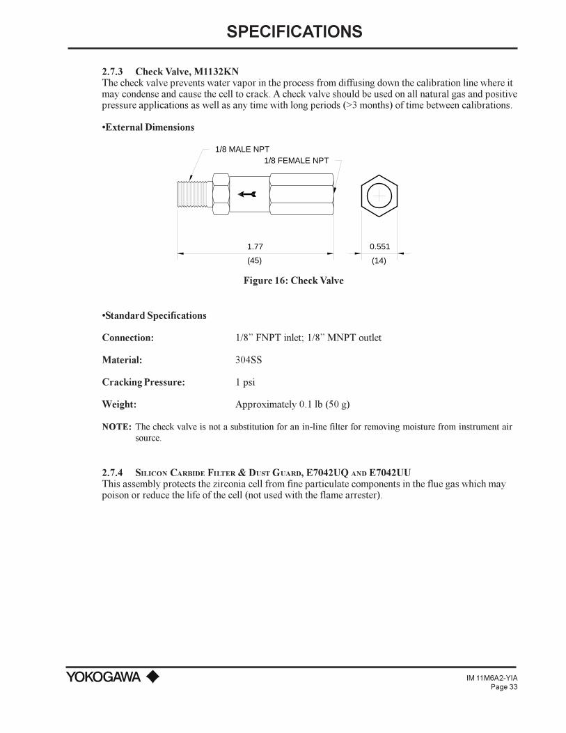
2.7.3 Check Valve, M1132KNThe check valve prevents water vapor in the process from diffusing down the calibration line where itmay condense and cause the cell to crack. A check valve should be used on all natural gas and positivepressure applications as well as any time with long periods (>3 months) of time between calibrations.
External Dimensions
1.77
(45)
1/8 MALE NPT1/8 FEMALE NPT
0.551
(14)
Figure 16: Check Valve
Standard Specifications
Connection: 1/8 FNPT inlet; 1/8 MNPT outlet
Material: 304SS
Cracking Pressure: 1 psi
Weight: Approximately 0.1 lb (50 g)
NOTE: The check valve is not a substitution for an in-line filter for removing moisture from instrument airsource.
2.7.4 SILICON CARBIDE FILTER & DUST GUARD, E7042UQ AND E7042UUThis assembly protects the zirconia cell from fine particulate components in the flue gas which maypoison or reduce the life of the cell (not used with the flame arrester).

SPECIFICATIONS
IM 11M6A2-YIAPage 34
External Dimensions
120˚90˚
GAS FLOW
2.36
(60.0)
3.15
(80.0)
1.70
(43.
3)
1.91
(48.
6)
1.73
(44.0)2-M6
CARBORUNDUM FILTER
(E7042UQ)
GUARD
(E7042UU)
FILTER AND GUARD
Figure 17: Filter and Dust Guard
Standard Specifications
Mesh: 70 micron (Filter)
Material: Carborundum (Filter), 316SS
Max. Temperature Rating: 932ºF (500ºC)
Connection: Stainless steel bolts
Weight: Approximately 1.6 lbs
2.7.5 Fly Ash Filter, M1100DAThe fly ash filter is for high dust applications such as coal fired boilers, kilns and bark boilers.
External Dimensions
(REF)2.60
8.10
(REF)
(REF)
END OF O PROBE2
7.0
THIS VIEW SHOWS THE
AS IT IS INSTALLED.(PROCESS FLOW WILL BE DOWN)
SIDE VIEW OF THE FILTER
FLOW
C-CLAMP CONNECTION
Figure 18: Fly Ash Filter
SPECIFICATIONS
IM 11M6A2-YIAPage 35
Standard Specifications
Mesh: 10 Micron (Filter)
Material: 316 Sintered stainless steel
Max. Temperature Rating: 572ºF (300ºC)
Connection: Stainless steel C-clamp with bolt
Weight: Approximately 1.5 lbs
2.7.6 HASTELLOY X SINTERED FILTER ASSEMBLY, M1100DA-2Designed for use in applications above 572ºF (300ºC), this filter addresses blockage and coatingproblems experienced by tough applications.
External Dimensions
Refer to Figure 17
Standard Specifications
Mesh: 10 Micron (Filter)
Material: Hastelloy x (See Note)
Max. Temperature Rating: 1292ºF (700ºC)
Connection: Stainless steel C-clamp with bolts
Weight: Approximately 1.8 lbs
NOTE: M1100DA-2 is not suitable for Recovery Boiler Applications.
2.7.7 Quick Disconnect Cable (/A option on probe)Quick disconnect connectors are used on the detectors heater and signal cables for easy wireinstallations and maintenance. See model ZO21D detectors for pre-attached male connectors inSection 1 (/A options shown). Field connectors must be ordered separately (WZ... options shown).
SPECIFICATIONS
IM 11M6A2-YIAPage 36
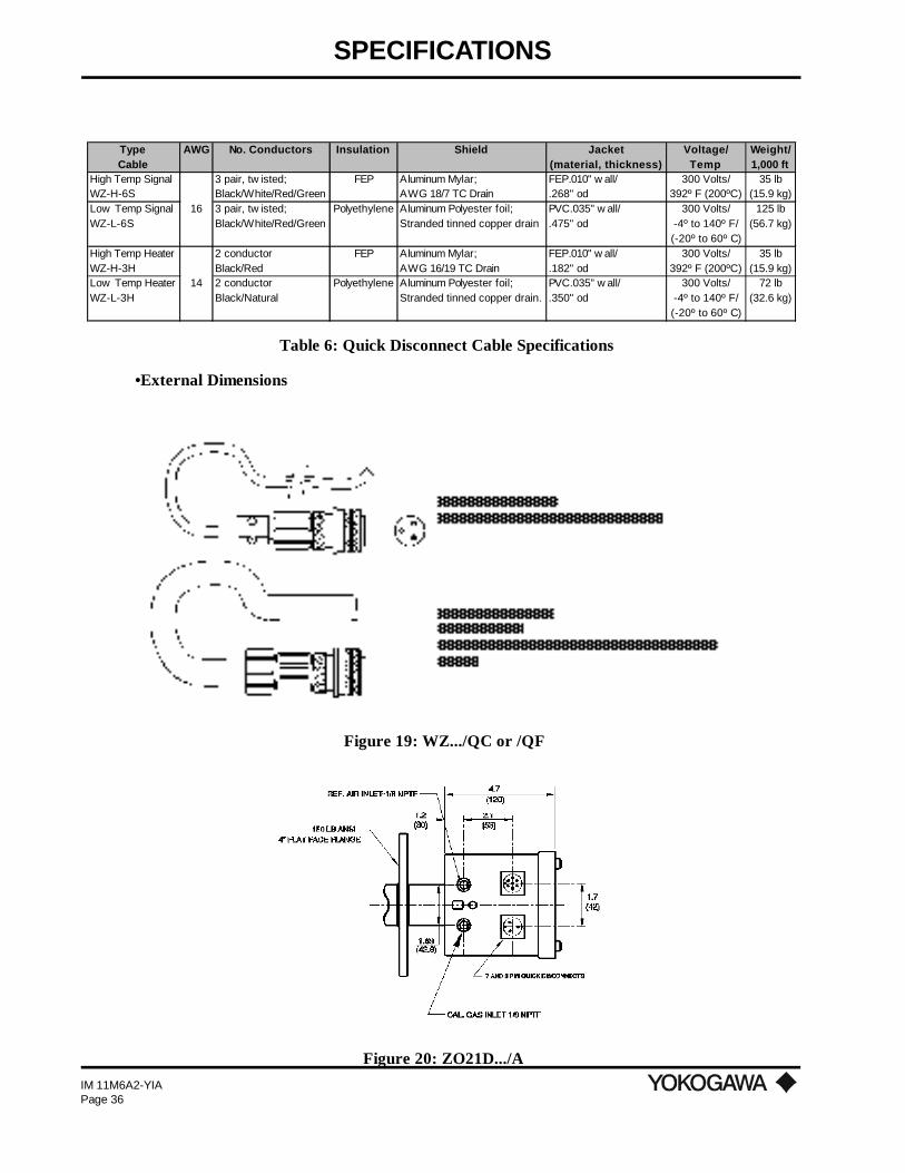
Type AWG No. Conductors Insulation Shield Jacket Voltage/ Weight/Cable (material, thickness) Temp 1,000 ft
High Temp Signal 3 pair, tw isted; FEP Aluminum Mylar; FEP.010" w all/ 300 Volts/ 35 lbWZ-H-6S Black/White/Red/Green AWG 18/7 TC Drain .268" od 392º F (200ºC) (15.9 kg)Low Temp Signal 16 3 pair, tw isted; Polyethylene Aluminum Polyester foil; PVC.035" w all/ 300 Volts/ 125 lbWZ-L-6S Black/White/Red/Green Stranded tinned copper drain .475" od -4º to 140º F/ (56.7 kg)
(-20º to 60º C)High Temp Heater 2 conductor FEP Aluminum Mylar; FEP.010" w all/ 300 Volts/ 35 lbWZ-H-3H Black/Red AWG 16/19 TC Drain .182" od 392º F (200ºC) (15.9 kg)Low Temp Heater 14 2 conductor Polyethylene Aluminum Polyester foil; PVC.035" w all/ 300 Volts/ 72 lbWZ-L-3H Black/Natural Stranded tinned copper drain. .350" od -4º to 140º F/ (32.6 kg)
(-20º to 60º C)
Table 6: Quick Disconnect Cable Specifications
•External Dimensions
Figure 19: WZ.../QC or /QF
Figure 20: ZO21D.../A

SPECIFICATIONS
IM 11M6A2-YIAPage 37
Model and Code
ZO21D WIRING - SIGNAL CABLECABLE TEMPERATURE RATING
WZ-H High temp cable (FEP jacket (up to 390ºF) (200ºC))WZ-L Low temp cable (PVC jacket (up to 140ºF (60ºC))
CABLE LENGTH (feet)-3H-0005 5' Heater Cable (3-Conductor)-6S-0005 5' Signal Cable (6-Conductor)-3H-0010 10' Heater Cable (3-Conductor)-6S-0010 10' Signal Cable (6-Conductor)-3H-0015 15' Heater Cable (3-Conductor)-6S-0015 15' Signal Cable (6-Conductor)-3H-0020 20' Heater Cable (3-Conductor)-6S-0020 20' Signal Cable (6-Conductor)-3H-0025 25' Heater Cable (3-Conductor)-6S-0025 25' Signal Cable (6-Conductor)-3H-0030 30' Heater Cable (3-Conductor)-6S-0030 30' Signal Cable (6-Conductor)-3H-0040 40' Heater Cable (3-Conductor)-6S-0040 40' Signal Cable (6-Conductor)-3H-0050 50' Heater Cable (3-Conductor)-6S-0050 50' Signal Cable (6-Conductor)-3H-0100 100' Heater Cable (3-Conductor)-6S-0100 100' Signal Cable (6-Conductor)-3H-0200 200' Heater Cable (3-Conductor)-6S-0200 200' Signal Cable (6-Conductor)-3H-0500 500' Heater Cable (3-Conductor)-6S-0500 500' Signal Cable (6-Conductor)
CONNECTION 1
/QC Quick disconnect w /cable clamp 1
/QFQuick disconnect w /flex conduit adapter (1/2" NPTM) 2, 3
CAUTION: WZ-H-6S-0500/QF w ill add a soldered quick disconnect f itting to the end of the 500 foot low temperature cable, w ith 2 separate Flex Conduit adapter f ittings (1/2" NPT). The customer w ill probably use a junction box close to the probe, and run the remainder several hundred feet from the junction box to the converte
NOTES:1) Must select /A option for the ZO21D probe quick disconnects.2) The quick disconnect w ith cable clamp (/QC option) can only be used w ith the Low Temperature (WZ-L...) cable.3) The quick disconnect w ith f lex conduit adapter (/QF) f ittings can only be used w ith the High Temperature (WZ-H..) cable.4) The 1/2" f lex conduit must be ordered separately. See WZ-FC information.

SPECIFICATIONS
IM 11M6A2-YIAPage 38
2.7.8 Flexible Metallic Conduit, WZ-FCThis jacketed, liquid-tight, flexible metallic conduit provides complete protection from liquids andvapors. It has an absorbing motion and withstands severe vibration and tight bending. The conduitjacket is a special thermoplastic rubber compound. Its applicable temperature range is from -76º to302ºF (-60º to 150ºC), with intermittent excursions to 329ºF (165ºC).
Standard Specifications
Size: 0.5 inches
ID: 0.622 min / 0.642 max
OD: 0.820 min / 0.840 max
Inside Bend Radius: 0.2 inch
Weight per 100 feet: 27 pounds
Model and CodePART NUMBER OPTIONAL ITEMS
M1132XP 1/2" Flexible Conduit(order quantity is conduit length in feet)

INSTALLATION
IM 11M6A2-YIAPage 39
III. INSTALLATION
3.1 INSTALLATION OF THE ZO21D-L DETECTOR
3.1.1 Installation SiteNote the following when installing the detector:
1) Easy access to the detector for maintenance work.2) Ambient temperature does not exceed 176ºF (80ºC).3) A clean environment free of corrosive gases.4) Minimum vibration.
3.1.2 Probe Insertion HoleIncludes those analyzers equipped with a probe supporter and probe protector. When preparing theprobe insertion hole, the following should be taken into consideration:
1) The detector probe tip should not be mounted above the horizontal.2) If the probe length is greater than 2 meters (10 feet), the detector requires a probe support
or protector.3) The probe should be situated so that the sensor is at a right angle to the gas flow
NOTE: To prevent the sensor from deterioration due to condensation, DO NOT mount the probe above thehorizontal.
WITHIN THIS ANGLE
(VERTICAL)
(HORIZONTAL)
ANSI CLASS 150#, OR JIS FLANGE
3.94
(100
)
(52
MIN
.)
3.94
(100)
2.05
" M
IN.
WESTINGHOUSE FLANGE
ANSI CLASS 3", 150# FF FLANGE
4-ø0.75(19.1) HOLESON A ø6.0(152.4) BC
4-ø0.45(11.5) HOLESON A ø5.0(127.0) BC
ANSI CLASS 2", 150# FF FLANGE
4-ô0.75(19.1) HOLESON A ø4.75(120.7) BC
ø6.0(152.4)
ANSI CLASS 4", 150# FF FLANGE
JIS FLANGE
ON A ø7.5(190.5) BC 8-ø0.75(19.1) HOLES
ø9.0(228.6)
ø6.1(155.0)
ø7.5(190.5)
Figure 21: Probe Insertion Hole
INSTALLATION
IM 11M6A2-YIAPage 40
3.1.3 ZO21D-L Detector InstallationThe cell (sensor) at the tip of the detector is made of ceramic (zirconia). The heater is made of aquartz type material; therefore, care should be taken to avoid any mechanical shock or jarring to theprobe such as dropping. Use a suitable gasket on the flange surface to prevent gas leakage. The gasketmaterial should be heatproof and corrosion-proof. If corrosion is a prevalent problem at the flange,request derakane coating when ordering probes. See accessories.
The following should be taken into consideration when mounting the detector.1) The zirconia cell is packaged inside of the ZO21D detector box, in a styrofoam cup.
Remove the cell, and using a 5/16" wrench, secure the cell as shown in Figure 22. Thebolts are tightened according to the sequence shown. Use approximately 52 lb•in (60kg•cm) of torque. Please note that bolts are pre-attached to the ZO21D detector, and arenot inside of the styrofoam cup with the zirconia cell.
2) Accessories (optional)Attach filter to detector, if purchased, according to instructions found in Section 3.1.5.Install probe protector, or support, according to instructions found in Section 3.1.8.
3) Place gasket between probe and process flange connection. The gasket is used to preventleaks. If a protector or support is used, also place gasket between all flange surfaces toprevent leaks.
4) Carefully insert the probe into the process, and secure the bolts and washers of the flangeusing a wrench. If a filter or probe protector is used, note the probe positioning as de-scribed in Section 3.1.5 for the filter, and Section 3.1.8 for the probe protector.
5) In a case where the detector is mounted horizontally, the cable lead-in hole on the junc-tion box of the detector should face downward.
Flange Specification Part Name QuantityGasket (same hole pattern as f lange) 1
ANSI 4", 150# FF Bolts (5/8 - 11 UNC x 2-1/2") 8Nuts (5/8 - 11 UNC) 8Washers (5/8") 16
Gasket (same hole pattern as f lange) 1ANSI 3", 150# FF Bolts (5/8 - 11 UNC x 2-1/2") 4
Nuts (5/8 - 11 UNC) 4Washers (5/8") 8
Gasket (same hole pattern as f lange) 1JIS 5K - 65 Bolts (M12 x 50) (1/2 - 13 UNC x 2") 4
Nuts (M10) (3/8 - 16 UNC) 4Washers (12 mm) (5/8") 8
Gasket (same hole pattern as f lange) 1Westinghouse Flange Bolts (M10 x 50) (3/8 - 16 x 2") 4
Nuts (M10) (3/8 - 16 UNC) 4Washers (10mm) (3/8") 8
Table 7: Mounting parts required

INSTALLATION
IM 11M6A2-YIAPage 41
BOLT
SPRING WASHER
FILTER RETAINER
FILTER
SENSOR (CELL)
CALIBRATIONGAS TUBE
CONTACT
O RING(METALLIC)
U-SHAPEDPIPE
Figure 22: Parts in Sensor Assembly
3.1.4 Installation of ZO21D-L AccessoriesIn order to extend the useful life of the probe, accessories are used. The following is a list ofaccessories for the low temperature detector, model ZO21D-L, along with installation instructions. Allinstructions assume that the zirconia cell has been previously installed, as described above in Section3.1.3.
3.1.5 Silicon Carbide Filter (E7042UQ) and Dust Guard (E7042UU) InstallationThe dust filter (E7042UQ) is used to protect the sensor from low concentrations of dust. Install thefilter as follows:
1) Remove the sensor bolts (4) and washers .These bolts are not used with filter mounting. The filter assembly includes bolts. It isrecommended that you keep the original bolts since operation without a filter may berequired in the future.
Figure 23: Dust Filter and Guard
2) Mount the dust filter as follows:Attach the filter with the supplied bolts and washers. Tighten each bolt to 52 lb•in (60kg•cm) torque.
3) If dust concentration is high and gas flow exceeds 10 m/sec, a dust guard (E7042UU) isrecommended. Attach the dust guard with the open side away from the flow mount to thedetector probe with two screws. Tighten the screws, matching them with the probegrooves.
4) Position the probe's dust guard upstream and perpendicular to the gas flow.

INSTALLATION
IM 11M6A2-YIAPage 42
3.1.6 Fly Ash Filter Installation (M1100DA or M1100DA-2)1) Carefully note direction of flow and place filter over end of probe. Locate the C-clamp
approximately 7.0 in (17.78 cm) from the probe tip.2) After filter is located over the probe, tighten the socket head bolt until the filter will not
move. Do not overtighten.3) Put the hexhead cap screws (2) through the washers into the filter holes and securely
tighten each bolt.4) Mark the flange to show the position of the filter shield. Position the probe so that the
shield portion of the filter upstream and perpendicular to the gas flow.
(REF)2.60
8.10
(REF)
(REF)
END OF O PROBE2
7.0
THIS VIEW SHOWS THE
AS IT IS INSTALLED.(PROCESS FLOW WILL BE DOWN)
SIDE VIEW OF THE FILTER
FLOW
C-CLAMP CONNECTION
Figure 24: Fly Ash Filter
3.1.7 Flame Arrester (/F option)If a flame arrester is used with the probe, a filter is not required. The flame arrester extinguishesflames generated by the zirconia cell (maintained at 1382ºF (750ºC)) and cools the hot gases beforethey escape, thereby preventing the detector from causing an explosion or fire in the duct.
1) Thread the flame arrester to the ZO21D probe near the tip.2) Thread the 2 bolts to the flame arrester in the holes provided in order to prevent any
movement of the flame arrester.
3.1.8 Detector with probe support or protector1) Attach the guide ring of the probe support to the detector 1.5 m from the probe flange,
and affix it with two screws. Tighten the screws firmly.2) Insert the gasket supplied by the user between the flange surfaces and mount the probe
support. Mount the probe protector so that the opening at the tip is located on the down-stream side of the gas to be analyzed.
3) Make sure the 4 bolts used to attach the zirconia cell to the probe are tightly secured.4) For probe supports, install the support collar 57 inches (1447 mm) from the face of the
flange. Tighten screws to a 52 lb•in (60 kg•cm) torque. If a probe protector is usedinstead of a support, install the support collar 9 inches (228 mm) from the probe tip.
NOTE: Clamps are used to prevent damage to the probe and to allow easy removal of the probe.
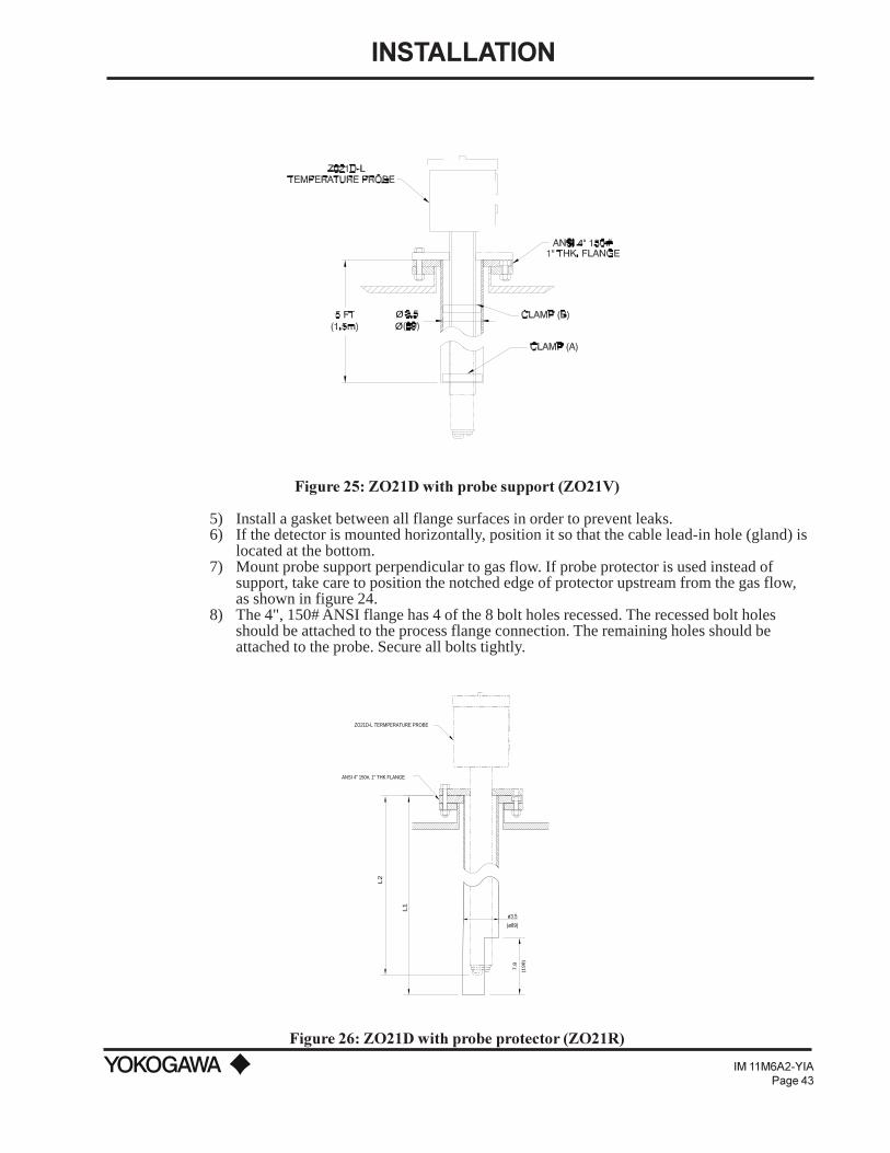
INSTALLATION
IM 11M6A2-YIAPage 43
ØØ
Figure 25: ZO21D with probe support (ZO21V)
5) Install a gasket between all flange surfaces in order to prevent leaks.6) If the detector is mounted horizontally, position it so that the cable lead-in hole (gland) is
located at the bottom.7) Mount probe support perpendicular to gas flow. If probe protector is used instead of
support, take care to position the notched edge of protector upstream from the gas flow,as shown in figure 24.
8) The 4", 150# ANSI flange has 4 of the 8 bolt holes recessed. The recessed bolt holesshould be attached to the process flange connection. The remaining holes should beattached to the probe. Secure all bolts tightly.
L1
L2
7.8
(198)
(ø89)
ø3.5
ANSI 4" 150#, 1" THK FLANGE
ZO21D-L TERMPERATURE PROBE
Figure 26: ZO21D with probe protector (ZO21R)

INSTALLATION
IM 11M6A2-YIAPage 44
3.2 INSTALLATION OF THE HIGH-TEMPERATURE DETECTOR
3.2.1 Installation SiteThe following should be taken into consideration.
1) Easy access to the detector for inspection and maintenance work.2) The ambient temperature should not be too high (below 300ºF (150ºC)) nor should the
terminal box be subjected to radiant heat.3) No corrosive gas present in surrounding atmosphere.4) No vibration should be allowed.5) The gas should satisfy the conditions as described in the specifications chapter.
3.2.2 Probe Insertion HoleA high-temperature detector consists of a detector ZO21D-H and high temperature probe adapter(ZO21P) and the auxiliary ejector.
The probe insertion hole should be prepared as follows:1) If the transport tube is made of silicon carbide (SiC), the probe hole should be prepared
so that the tube is placed vertically (no more than a 5º tilt.)2) If the transport tube is made of stainless steel and the probe adapter positioned horizon-
tally, it is important that the probe tip remains below the probe base.
TRANSPORT TUBEMADE OF 310 SS, OR SILICONCARBIDE (SiC)3.3ft(1.0m) OR 5.0ft(1.5m) LENGTH.
HIGH-TEMPERATURE DETECTORINSTALLED WHERE THE AMBIENTTEMPERATURE IS LESS THAN 302˚F(150˚C). ITS STRUCTURE ISTHE SAME AS THAT OF A GENERALPURPOSE DETECTOR (EXCEPT FORTHE FLANGE SIZE). PROBE LENGTHIS 6" (150mm).
SAMPLE GAS OUTLET PORTWHEN THE PRESSURE OF THEMEASUREMENT GAS IS NEGATIVE,CONNECT THE EJECTOR ASSEMBLYHERE. IF THE TEMPERATURE DOESNOT DECREASE TO LESS THAN 1112˚(600˚C) UNDER HIGH PRESSURE,CONNECT A NEEDLE VALVE.
MOUNTING FLANGE4" ANSI 150# FLANGE
Figure 27: ZO21PH High Temperature Tee Adapter
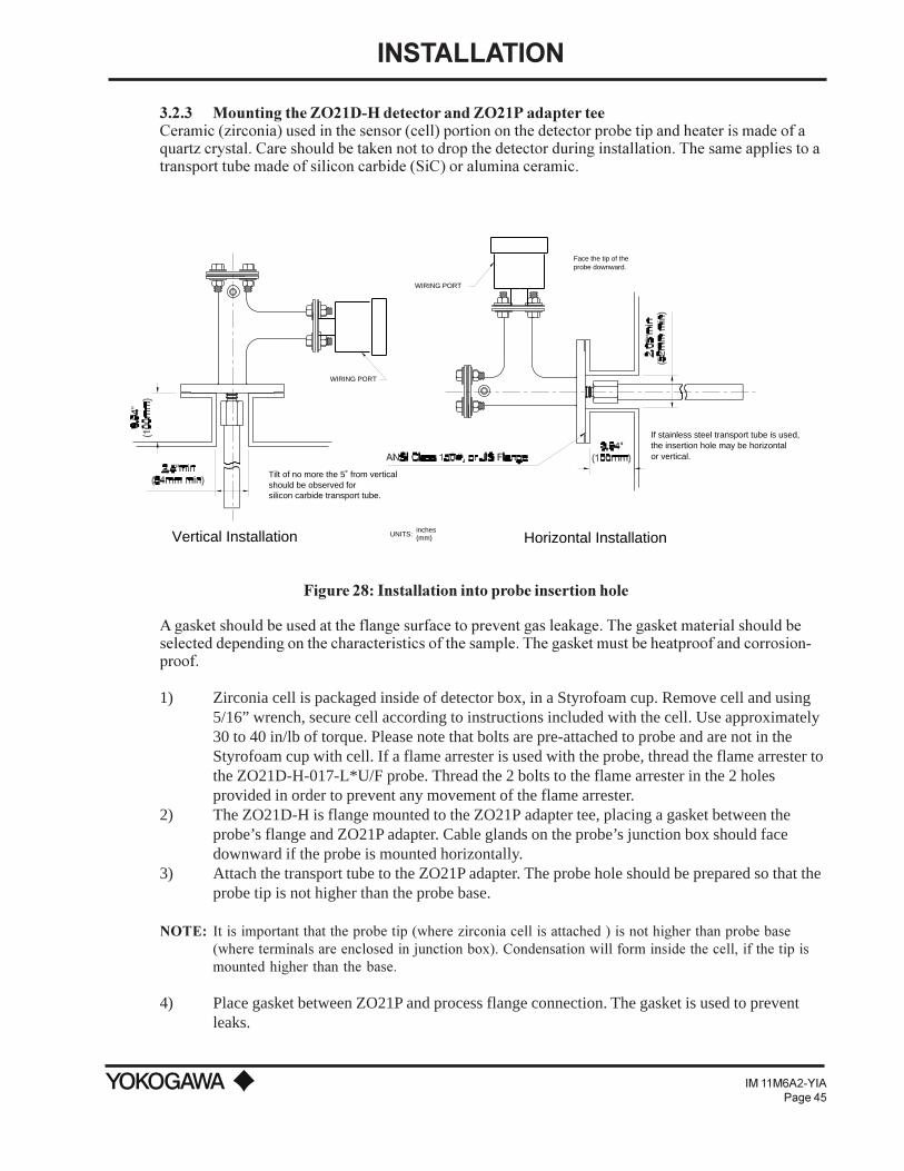
INSTALLATION
IM 11M6A2-YIAPage 45
3.2.3 Mounting the ZO21D-H detector and ZO21P adapter teeCeramic (zirconia) used in the sensor (cell) portion on the detector probe tip and heater is made of aquartz crystal. Care should be taken not to drop the detector during installation. The same applies to atransport tube made of silicon carbide (SiC) or alumina ceramic.
WIRING PORT
Tilt of no more the 5˚ from verticalshould be observed for
WIRING PORT
Face the tip of theprobe downward.
silicon carbide transport tube.
the insertion hole may be horizontalIf stainless steel transport tube is used,
Vertical Installation Horizontal InstallationUNITS:inches(mm)
or vertical.
Figure 28: Installation into probe insertion hole
A gasket should be used at the flange surface to prevent gas leakage. The gasket material should beselected depending on the characteristics of the sample. The gasket must be heatproof and corrosion-proof.
1) Zirconia cell is packaged inside of detector box, in a Styrofoam cup. Remove cell and using5/16” wrench, secure cell according to instructions included with the cell. Use approximately30 to 40 in/lb of torque. Please note that bolts are pre-attached to probe and are not in theStyrofoam cup with cell. If a flame arrester is used with the probe, thread the flame arrester tothe ZO21D-H-017-L*U/F probe. Thread the 2 bolts to the flame arrester in the 2 holesprovided in order to prevent any movement of the flame arrester.
2) The ZO21D-H is flange mounted to the ZO21P adapter tee, placing a gasket between theprobe’s flange and ZO21P adapter. Cable glands on the probe’s junction box should facedownward if the probe is mounted horizontally.
3) Attach the transport tube to the ZO21P adapter. The probe hole should be prepared so that theprobe tip is not higher than the probe base.
NOTE: It is important that the probe tip (where zirconia cell is attached ) is not higher than probe base(where terminals are enclosed in junction box). Condensation will form inside the cell, if the tip ismounted higher than the base.
4) Place gasket between ZO21P and process flange connection. The gasket is used to preventleaks.

INSTALLATION
IM 11M6A2-YIAPage 46
5) If transport tube is mounted horizontally, and extends longer than 1 meter, a support tubemust be used (3" O.D. minimum).
6) Carefully insert the transport tube into the process, and secure the bolts and washers of theZO21P flange using a wrench.
7) Insulate ZO21P and all metal surfaces.8) If the process duct pressure is negative, attach an eductor to the ZO21P adapter as shown in
figure 29.
However, if the pressure exceeds 2 inH2O (50 mmH2O), connect a needle valve at the 1/4" FNPTfitting for the eductor port so that the sample gas exhaust volume can be controlled.
3.2.4 Installation of ZO21D-H High Temperature System:When the sample exceeds 1200 ºF (650 ºC), a probe adapter tee is used to cool the sample via naturalconvection before reaching the probe.
0
10
BAR100 x kPa
psi
1.0
20
30
2.0
60
504.0
3.0
40
SAMPLE EXHAUST
"A"
"A"
INSTRUMENT AIR SUPPLY
REGULATOR SHOULD BE CONNECTED TOINCOMING CLEAN, DRY INSTRUMENT AIRSET AT 60 psi MAX.
REGULATOR
NOT TO SCALE
EXHAUST OUTLET
1/4" MNPT
AIR EDUCTOR
TO REGULATOR (SEE VIEW "A-A")
VACUUM INLET
1/8" FNPT
Figure 29: ZO21P High Temperature Adapter Tee
3.2.5 Auxiliary Ejector Assembly, M1132KEEjector InstallationWhen the process pressure is negative or equal to that of atmosphere, an ejector is used to create apositive force that draws a sample through the high temperature assembly. There is a choice of eitheran air or water ejector. Water is self-cleaning, and is used when the sample contains a large volume ofparticulates that would cause the exhaust of the eductor to plug if air were used. The ejector isattached to the high temperature adapters eductor port fitting, which is a 1/4" FNPT connection.When the eductor return option (/ER) is selected, an air eductor is pre-attached to the ZO21P adapter,and the exhaust is returned to the process via 316 stainless steel tubing. However, for all otheroptions, the User must provide the exhaust plumbing to atmosphere, drain, etc. Note the followingprocedure for installing an eductor (refer to figure 29):
INSTALLATION
IM 11M6A2-YIAPage 47
1) Attach the eductor to the adapter tee’s 1/4" FNPT port. Use teflon tape or a suitablealternate on the threads in order to prevent leaks. Also, install all compression fittingscorrectly. Take care to attach the inlet of the eductor to the adapter, and not the exhaust!
2) Use 316 stainless steel tubing to attach the supply (either water or air as determined byeductor selection) to the eductor. A regulator is used between the supply and eductor inorder to adjust the pressure of the supply (air or water). For air, a 0 to 60 PSI regulator issufficient. For water, a 0 to 50 GPM regulator is recommended. DO NOT start theeductor supply until the exhaust has been piped appropriately for the application.
3) Use 316 SS tubing to pipe the sample that exits the exhaust of the eductor to drain,atmosphere, or others as determined by the safety procedures dictated by the application.Use a teflon tape or suitable alternate on the threads in order to prevent leaks.
Determining the Eductor Flowrate/PressureIn order to determine the flowrate or pressure of the supply (either water or air), the ZA8C analyzermust be completely wired to the probe. It is recommended that all parts are wired and plumbedappropriately, which includes the ZA8C analyzer, ZO21D probe, and calibration unit (either MC1 orAC1). If the installation of all components is completed, turn on the ZA8C analyzer. After theanalyzer is no longer in the warm up mode and the LED begins to display the O2 value (typically20.6 vol % O2), turn on the supply to the eductor, starting with a low setting and gradually increasethe regulator setting until the O2 reading displayed on the LED of the ZA8C begins to drop. Do notincrease the flow or pressure past this value. Wait until the reading begins to stabilize. If the readingdoes not stabilize after a few minutes, reduce the flow or pressure slowly until the reading stabilizes.Once the reading has stabilized, this is the setpoint for the supply to the eductor.
IMPORTANT NOTE: The supply to the eductor must remain at this setting in order for the sample tocontinuously flow from the process.
3.3 INSTALLATION OF THE ZA8C CONVERTER
3.3.1 LocationInstall the converter to meet the following:
1) Easy access to displays and keyboard entry.2) Maintenance and inspection are easily carried out.3) Ambient temperature does not exceed 131ºF (55ºC) and temperature variations are
minimal.4) Humidity is moderate (40 to 75% RH) and no corrosive gases are present.5) Where vibration is limited.6) The detector is installed within 1,500 feet maximum.
NOTE: If the ambient atmosphere contains corrosive gases, install air purging.
3.3.2 MountingThe converter may be pipe, wall or panel mounted.
Pipe MountingMount the converter as described below:1) Use a vertical pipe (O.D. approximately 2") of sufficient strength for mounting the converter.2) Attach firmly to the pipe in the procedure shown in Figure 30 using the enclosed mounting
hardware.a. Screw four bolts into the mounting bracket.b. Hold the pipe between the bracket and mounting fitting, passing bolts through the bracket
holes.

INSTALLATION
IM 11M6A2-YIAPage 48
c. Clamp the mounting fitting to the pipe. Set washers onto the bolts and fully fasten thenuts.
Figure 30: Pipe Mounting Procedure
Wall Mounting1) Drill mounting holes as shown below.
Figure 31: Drilling Mounting Holes
2) Secure the converter on the wall using four screws.
Figure 32: Mounting to the Wall
NOTE: For wall mounting, the pipe bracket and bolts are not used.
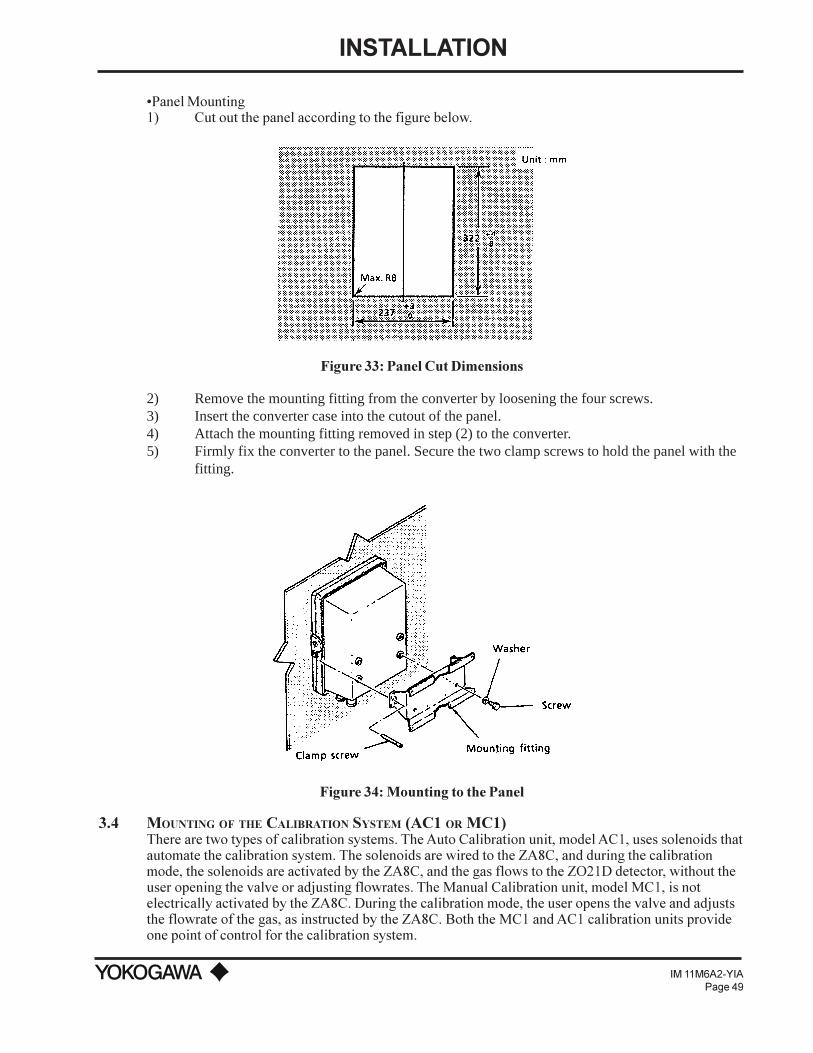
INSTALLATION
IM 11M6A2-YIAPage 49
Panel Mounting1) Cut out the panel according to the figure below.
Figure 33: Panel Cut Dimensions
2) Remove the mounting fitting from the converter by loosening the four screws.3) Insert the converter case into the cutout of the panel.4) Attach the mounting fitting removed in step (2) to the converter.5) Firmly fix the converter to the panel. Secure the two clamp screws to hold the panel with the
fitting.
Figure 34: Mounting to the Panel
3.4 MOUNTING OF THE CALIBRATION SYSTEM (AC1 OR MC1)There are two types of calibration systems. The Auto Calibration unit, model AC1, uses solenoids thatautomate the calibration system. The solenoids are wired to the ZA8C, and during the calibrationmode, the solenoids are activated by the ZA8C, and the gas flows to the ZO21D detector, without theuser opening the valve or adjusting flowrates. The Manual Calibration unit, model MC1, is notelectrically activated by the ZA8C. During the calibration mode, the user opens the valve and adjuststhe flowrate of the gas, as instructed by the ZA8C. Both the MC1 and AC1 calibration units provideone point of control for the calibration system.

INSTALLATION
IM 11M6A2-YIAPage 50
3.4.1 LocationThe following guidelines should be used when selecting a location for the calibration unit.1) Easily accessible for maintenance and inspections.2) As close to the ZO21D probes as practical, which will minimize the amount of tubing
required for plumbing. The MC1 is mounted near the ZA8C converter.3) Ambient temperature does not exceed 131ºF (55ºC).4) Humidity is moderate and no corrosive gases are present.
NOTE: Use air purge for the AC1 enclosure if corrosive gas or high dust present.
5) Minimal vibration area.6) Instrument Air is available.
3.4.2 Mounting (AC1)The AC1 unit is designed for wall mounting by securing the four standoffs with bolts.Allow sufficient room to connect the cal gas and reference air tubing. Input gases (zero gas andinstrument air) are connected to the LEFT side, while all probe connections (cal lines and referenceair) are on the side. Mount the unit so that the terminal strip is easily visible for wiring purposes. TheAC1 unit is available with Nema 4 or Nema 4X enclosures and is provided with a key.
IMPORTANT NOTE: Unit must be mounted level, to ensure the accuracy of flowrates.
3.4.3 Mounting (MC1)The MC1 unit should be mounted as close as practical to the ZA8C oxygen converter, since the ZA8Cdisplays calibration instructions for opening valves during a calibration. The MC1 unit is designed forwall mounting by securing the four standoffs with bolts. Allow sufficient room to connect cal gas andreference air tubing. Input gases (zero gas and instrument air) are connected to the RIGHT side, whileall probe connections (cal lines and reference air) are on the LEFT side.
IMPORTANT NOTE: Unit must be mounted level, to ensure the accuracy of flowrates.
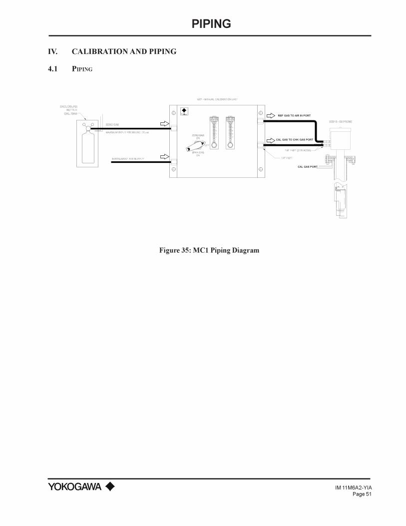
PIPING
IM 11M6A2-YIAPage 51
IV. CALIBRATION AND PIPING
4.1 PIPING
CAL GASADJUST 0.6LPM
REF AIRADJUST 0.8LPM
Figure 35: MC1 Piping Diagram
CAL GAS PORT
REF GAS TO AIR IN PORT
CAL GAS TO CHK GAS PORT
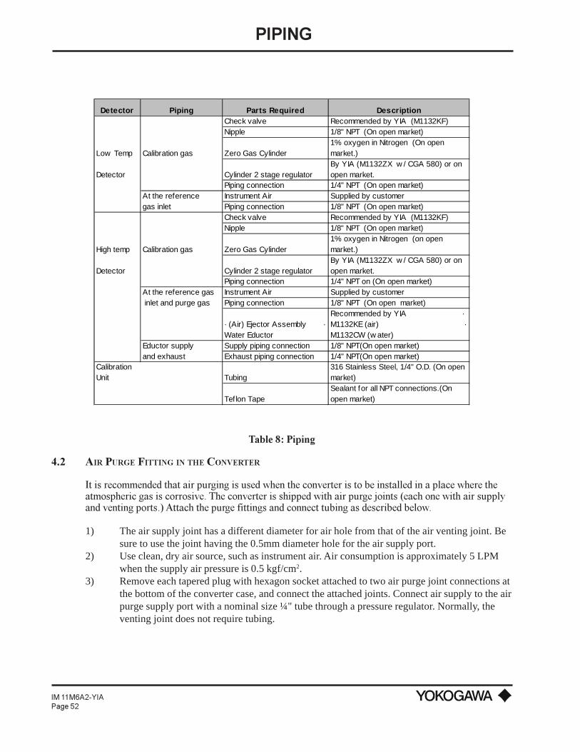
PIPING
IM 11M6A2-YIAPage 52
Detector Piping Parts Required DescriptionCheck valve Recommended by YIA (M1132KF)Nipple 1/8" NPT (On open market)
Low Temp Calibration gas Zero Gas Cylinder1% oxygen in Nitrogen (On open market.)
Detector Cylinder 2 stage regulatorBy YIA (M1132ZX w / CGA 580) or on open market.
Piping connection 1/4" NPT (On open market)At the reference Instrument Air Supplied by customergas inlet Piping connection 1/8" NPT (On open market)
Check valve Recommended by YIA (M1132KF)Nipple 1/8" NPT (On open market)
High temp Calibration gas Zero Gas Cylinder1% oxygen in Nitrogen (on open market.)
Detector Cylinder 2 stage regulatorBy YIA (M1132ZX w / CGA 580) or on open market.
Piping connection 1/4" NPT on (On open market)At the reference gas Instrument Air Supplied by customer inlet and purge gas Piping connection 1/8" NPT (On open market)
· (Air) Ejector Assembly · Water Eductor
Recommended by YIA · M1132KE (air) · M1132CW (w ater)
Eductor supply Supply piping connection 1/8" NPT(On open market)and exhaust Exhaust piping connection 1/4" NPT(On open market)
Calibration Unit Tubing
316 Stainless Steel, 1/4" O.D. (On open market)
Tef lon TapeSealant for all NPT connections.(On open market)
Table 8: Piping
4.2 AIR PURGE FITTING IN THE CONVERTER
It is recommended that air purging is used when the converter is to be installed in a place where theatmospheric gas is corrosive. The converter is shipped with air purge joints (each one with air supplyand venting ports.) Attach the purge fittings and connect tubing as described below.
1) The air supply joint has a different diameter for air hole from that of the air venting joint. Besure to use the joint having the 0.5mm diameter hole for the air supply port.
2) Use clean, dry air source, such as instrument air. Air consumption is approximately 5 LPMwhen the supply air pressure is 0.5 kgf/cm2.
3) Remove each tapered plug with hexagon socket attached to two air purge joint connections atthe bottom of the converter case, and connect the attached joints. Connect air supply to the airpurge supply port with a nominal size ¼" tube through a pressure regulator. Normally, theventing joint does not require tubing.
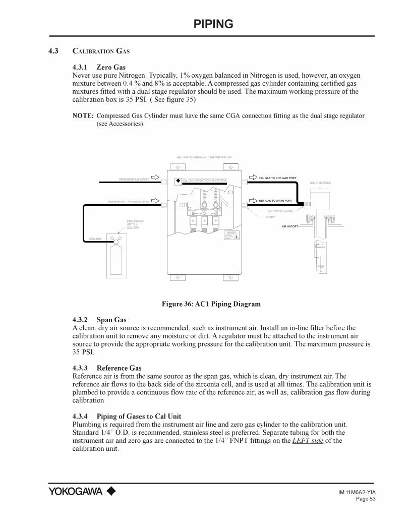
PIPING
IM 11M6A2-YIAPage 53
4.3 CALIBRATION GAS
4.3.1 Zero GasNever use pure Nitrogen. Typically, 1% oxygen balanced in Nitrogen is used, however, an oxygenmixture between 0.4 % and 8% is acceptable. A compressed gas cylinder containing certified gasmixtures fitted with a dual stage regulator should be used. The maximum working pressure of thecalibration box is 35 PSI. ( See figure 35)
NOTE: Compressed Gas Cylinder must have the same CGA connection fitting as the dual stage regulator(see Accessories).
SET ALL SWITCHES TO AUTO FOR NORMAL OPERATION
AUTOSPAN GAS
LPM AIR
ZERO GASAUTO
MANUALMANUAL
BLOCK
MANUAL
.2
AUTO
LPM AIR
.2
.4
.6
.4
2
Figure 36: AC1 Piping Diagram
4.3.2 Span GasA clean, dry air source is recommended, such as instrument air. Install an in-line filter before thecalibration unit to remove any moisture or dirt. A regulator must be attached to the instrument airsource to provide the appropriate working pressure for the calibration unit. The maximum pressure is35 PSI.
4.3.3 Reference GasReference air is from the same source as the span gas, which is clean, dry instrument air. Thereference air flows to the back side of the zirconia cell, and is used at all times. The calibration unit isplumbed to provide a continuous flow rate of the reference air, as well as, calibration gas flow duringcalibration
4.3.4 Piping of Gases to Cal UnitPlumbing is required from the instrument air line and zero gas cylinder to the calibration unit.Standard 1/4 O.D. is recommended, stainless steel is preferred. Separate tubing for both theinstrument air and zero gas are connected to the 1/4 FNPT fittings on the LEFT side of thecalibration unit.
AIR IN PORT
CAL GAS TO CHK GAS PORT
REF GAS TO AIR IN PORT

PIPING
IM 11M6A2-YIAPage 54
4.4 PIPING TO ZO21D PROBE
Tubing to the ZO21D probe is from the RIGHT side of the calibration unit. Run ¼" tubing from theauto cal unit to the 1/8 FNPT fitting on the ZO21D probe. The Reference Air tubing is connected tothe AIR IN port at the probe, and the Cal Gas tubing is connected to the CHK GAS port on theprobe. The AIR IN and CHK GAS ports are located on the bottom of the probe junction box near thecable gland holes. These ports require a 1/8 NPT fitting. Any unused ports must have a Teflon tapedplug. All probes have independent plumbing from other probes and are not to be teed at any point.Teflon tape or a suitable substitute is required to make an air tight seal.
IMPORTANT NOTE: To prevent leakage, all threaded fittings should have Teflon tape (or suitablealternate) and all compression fittings should be installed per manufacturers recommendations.In addition, a check valve is usually installed on the cal gas inlet of the probe to protect the caltubing from moisture contamination.
4.5 INITIAL FLOW RATE SETUP (AC1)
Ensure that the cal gas and reference air are properly plumbed to the left side of the AC1 auto cal unit.The zero gas and instrument air should be set at approximately 20 + 2 PSIG. Power is not needed toset the flow rates.
[8.1
5]
[1.50]
REFERENCE AIR
OUTLET
ZERO GAS
INLET
[5.90]
[7.71]
[9.84]
[1.25]
[13.
77]
[14.
57]
[6.97]
TO PROBESCAL. GAS
[4.0
0] INLET
SPAN GAS
101.
6
177.0
250.0
370.
0
31.8
206.
9
38.1
349.
8
150.0
195.7
mm[INCHES]
UNITS:
.5
1.0
2.5
3.0
3.0
3.0
.5
1.0
2.5
3.0
3.0
3.0
Figure 37: AC1 Piping
PIPING
IM 11M6A2-YIAPage 55
4.5.1 Setting the Reference Air Flow RateLocate the reference air flowmeters. Adjust the flow adjustment knob on the REFERENCE AIRFLOWMETER to 0.8 LPM or 800 ml/min.
4.5.2 Balancing Pressure drops in the cal linesFor accurate calibrations, the auto cal system must provide a fixed flow of Zero gas and Span gas (0.6LPM or 600 ml/min). To balance the pressure drops, perform the following steps:
These adjustments can be made with a flat tip screwdriver.
1. Locate the BLOCK and SPAN GAS SOLENOID. Using a screwdriver, turn the overridescrew to the manual position.
2. Use the flow regulator knob on the CAL GAS FLOWMETER to adjust the flow to 1.0 LPM.3. Switch the override screw of the SPAN GAS solenoid to AUTO.
Turn the override screw for the ZERO GAS solenoid to Manual.4. Adjust the pressure regulator on the zero gas cylinder for a flow of 1.0 LPM on the Calibra-
tion Gas flowmeter.
IMPORTANT: DO NOT USE THE flow regulator knob of the flowmeter to achieve thisflow rate!
5. Adjust the flow regulator knob on the Calibration Gas flowmeter until the flowmeterreads 0.6 LPM.
6. Verify that all the manual overrides are set back to AUTO.
Standard operation· The Reference Air flowmeter indicates 0.8 LPM during normal operation and calibration.· All manual overrides are set to the AUTO position.· The Calibration Gas flowmeter will show a flow of 0.6 LPM during Calibration only.
Before considering your calibration unit automated, it is a good practice to check for leaks along the full distance of thecal line tubing in addition to doing a CAL CHECK to confirm that the gases are plumbed correctly to each probe.
4.6 CHECKING FOR LEAKS
1) Locate the BLOCK SOLENOID. Turn the override screw on the BLOCK SOLENOID andSPAN SOLENOID to the manual position.
2) Use leak detection spray on all compression fittings and bends of the cal and reference linetubing.
3) Inspect the full length of the cal line to determine if there is a leak. Repair any leaks.4) After repairing the leaks, if any, return all solenoids to the auto position.
NOTE: For ZA8C programming values, see section 6.3.
4.7 MC1 FLOW RATE SETUPPerforming a CalibrationFor accurate calibrations, the manual cal system must provide a fixed flow of zero gas and span gas(0.6 LPM or 600 cc/min) during calibration. There are two flowmeters and one hand valve adjusterfor the MC1. The hand valve is used only during calibration to flow either span gas or zero gas to theprobe, using the Cal Gas flowmeter to indicate the flowrate. The Reference Air flowmeter is used to
PIPING
IM 11M6A2-YIAPage 56
flow the reference air for the ZO21D probe, and remains flowing at all times with a flowrate of 0.8LPM. The ZA8C display will prompt the User to perform the following steps, when programmed forOne Touch (TCH) calibration as follows (refer to figure 35):
1) Position the valve knob to Span Gas On. This will start the flow of Span Gas (or Air) to theprobe.
2) Adjust the Cal Gas flowmeter to show 0.6 LPM as the flowrate. Also, if necessary, adjust thereference flowmeter to show 0.8 LPM
3) To stop the flow of Span gas, position the valve knob to the OFF position.4) To start the flow of zero gas to the probe, position the valve knob to Zero Gas On.5) Adjust the Cal Gas flowmeter to show 0.6 LPM as a flowrate. Also, if necessary, adjust the
reference flowmeter to show 0.8 LPM.6) To stop the flow of Zero gas, position the valve knob to the OFF position.
WARNING: If reference air is used during calibration, the reference air must be left on after calibra-tion!!
Checking for Leaks for MC11) Position the valve to Span.2) Apply a leak detection spray on all compression fittings and bends of the cal line tubing for
the probe, the cal unit inlet, cal unit outlet, probe inlet for Cal Gas and reference air. Sprayboth the reference air and Cal Gas line.
3) Inspect the full length of the cal line to determine if there is a leak. Repair any leaks.4) After repairing the leaks, if any, return the valve to the OFF position. Set reference air flow-
meter to 0.8 LPM.
NOTE: For ZA8C programming values, see section 6.3.
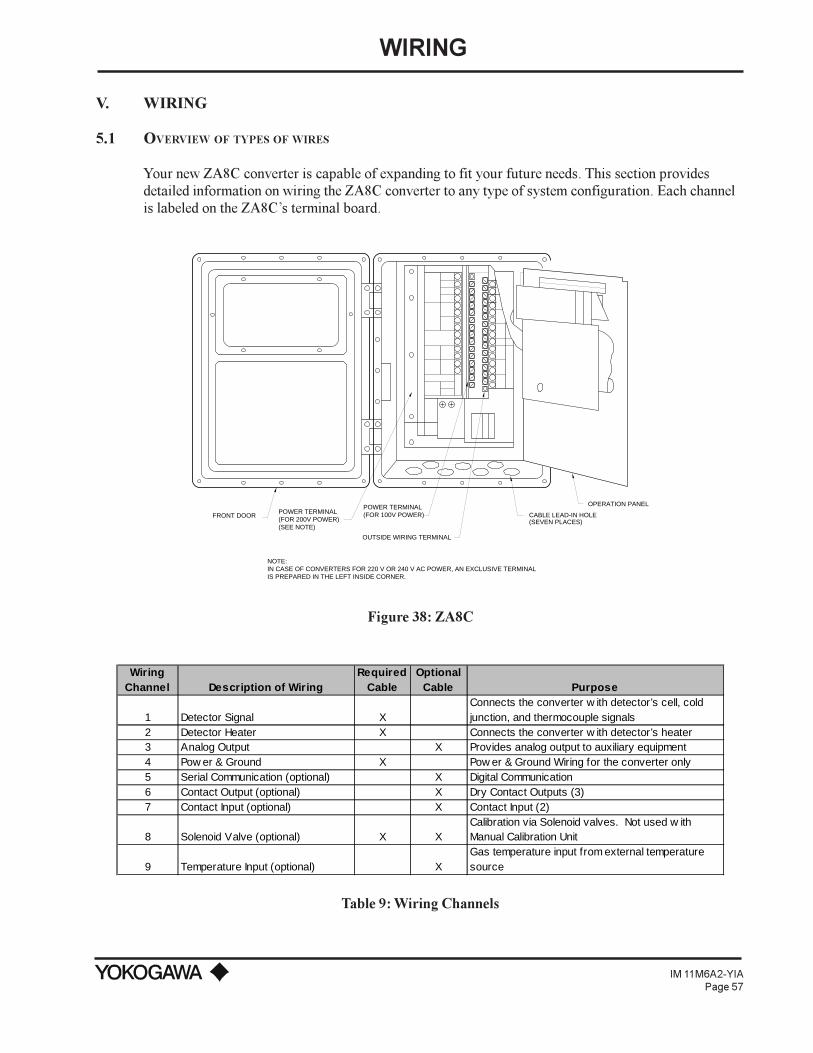
WIRING
IM 11M6A2-YIAPage 57
V. WIRING
5.1 OVERVIEW OF TYPES OF WIRES
Your new ZA8C converter is capable of expanding to fit your future needs. This section providesdetailed information on wiring the ZA8C converter to any type of system configuration. Each channelis labeled on the ZA8Cs terminal board.
OPERATION PANEL
CABLE LEAD-IN HOLE(SEVEN PLACES)
OUTSIDE WIRING TERMINAL
POWER TERMINAL(FOR 100V POWER)POWER TERMINAL
(FOR 200V POWER)(SEE NOTE)
FRONT DOOR
NOTE:IN CASE OF CONVERTERS FOR 220 V OR 240 V AC POWER, AN EXCLUSIVE TERMINALIS PREPARED IN THE LEFT INSIDE CORNER.
Figure 38: ZA8C
Wiring Channel Description of Wiring
Required Cable
Optional Cable Purpose
1 Detector Signal XConnects the converter w ith detector’s cell, cold junction, and thermocouple signals
2 Detector Heater X Connects the converter w ith detector’s heater3 Analog Output X Provides analog output to auxiliary equipment4 Pow er & Ground X Pow er & Ground Wiring for the converter only5 Serial Communication (optional) X Digital Communication6 Contact Output (optional) X Dry Contact Outputs (3)7 Contact Input (optional) X Contact Input (2)
8 Solenoid Valve (optional) X XCalibration via Solenoid valves. Not used w ith Manual Calibration Unit
9 Temperature Input (optional) XGas temperature input from external temperature source
Table 9: Wiring Channels

WIRING
IM 11M6A2-YIAPage 58
There are 7 cable wiring ports (i.e. rubber glands) on the bottom of the ZA8C converter. Keep thedetector signal cable separate at all times from the power and heater cables. The AC voltage cablesmust be kept separate from DC voltage cables at all times in order to prevent electrical noise problems.
5.1.1 Initial PreparationsThe oxygen converter, detector, and auto calibration units are supplied with rubber plugs alreadyinstalled in the cable ports. If corrosive gas is present, it may be necessary to purge the enclosures ofthe converter and calibration units. In such an instance, a watertight gland is used instead of the rubberplug. The ZA8C converter is shipped with purge connection pre-attached. The AC1 calibration unitdoes not have a purge connection.
When using wire conduit, the gland is removed, and a standard 3/4 (19 mm) conduit fitting is used.Note the following procedure for using the plastic watertight cable gland.1. Remove the rubber plug.2. Remove the nut from the cable gland and set the nut in the keyway inside of the cable bushing.3. Thread the gland over the cable, in the correct sequence.4. Screw the gland onto the nut from the outside, using a gasket to seal completely the space be-
tween the ZA8C case hole and the gland.
The ZO21D detector is supplied with 2 rubber plugs installed in the cable ports. The diameter of thecable bushing hole in the detector is 1.06 in (27 mm) If necessary, protect the cable by using a flexiblewire conduit of nominal diameter 3/4 (19 mm) The detector may need to be removed in the future formaintenance, so be sure to allow a sufficient cable length.
5.1.2 Safety Precaution During WiringNever apply power to the converter or any other device constituting a power circuit in combinationwith the converter, until all wiring is completed.
5.1.3 Power and Ground WiringThis wiring provides the converter with AC power and ground the converter. The detector and autocalibration units are powered from the ZA8C converter.
Case Ground
3432 33
ZA8C Converter
Case Ground
ZO21D detector
Power: 100, 110, 115 VAC, 50/60 Hz or,220, 240 VAC, 50/60 Hz
Figure 39: Power Wiring
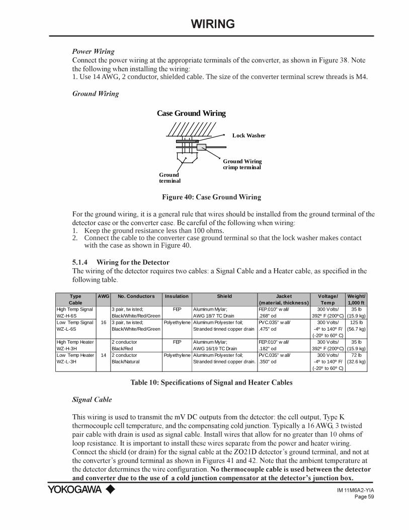
WIRING
IM 11M6A2-YIAPage 59
Power WiringConnect the power wiring at the appropriate terminals of the converter, as shown in Figure 38. Notethe following when installing the wiring:1. Use 14 AWG, 2 conductor, shielded cable. The size of the converter terminal screw threads is M4.
Ground Wiring
Case Ground Wiring
Groundterminal
Ground Wiringcrimp terminal
Lock Washer
Figure 40: Case Ground Wiring
For the ground wiring, it is a general rule that wires should be installed from the ground terminal of thedetector case or the converter case. Be careful of the following when wiring:1. Keep the ground resistance less than 100 ohms.2. Connect the cable to the converter case ground terminal so that the lock washer makes contact
with the case as shown in Figure 40.
5.1.4 Wiring for the DetectorThe wiring of the detector requires two cables: a Signal Cable and a Heater cable, as specified in thefollowing table.
Type AWG No. Conductors Insulation Shield Jacket Voltage/ Weight/Cable (material, thickness) Temp 1,000 ft
High Temp Signal 3 pair, tw isted; FEP Aluminum Mylar; FEP.010" w all/ 300 Volts/ 35 lbWZ-H-6S Black/White/Red/Green AWG 18/7 TC Drain .268" od 392º F (200ºC) (15.9 kg)Low Temp Signal 16 3 pair, tw isted; Polyethylene Aluminum Polyester foil; PVC.035" w all/ 300 Volts/ 125 lbWZ-L-6S Black/White/Red/Green Stranded tinned copper drain .475" od -4º to 140º F/ (56.7 kg)
(-20º to 60º C)High Temp Heater 2 conductor FEP Aluminum Mylar; FEP.010" w all/ 300 Volts/ 35 lbWZ-H-3H Black/Red AWG 16/19 TC Drain .182" od 392º F (200ºC) (15.9 kg)Low Temp Heater 14 2 conductor Polyethylene Aluminum Polyester foil; PVC.035" w all/ 300 Volts/ 72 lbWZ-L-3H Black/Natural Stranded tinned copper drain. .350" od -4º to 140º F/ (32.6 kg)
(-20º to 60º C)
Table 10: Specifications of Signal and Heater Cables
Signal Cable
This wiring is used to transmit the mV DC outputs from the detector: the cell output, Type Kthermocouple cell temperature, and the compensating cold junction. Typically a 16 AWG, 3 twistedpair cable with drain is used as signal cable. Install wires that allow for no greater than 10 ohms ofloop resistance. It is important to install these wires separate from the power and heater wiring.Connect the shield (or drain) for the signal cable at the ZO21D detectors ground terminal, and not atthe converters ground terminal as shown in Figures 41 and 42. Note that the ambient temperature atthe detector determines the wire configuration. No thermocouple cable is used between the detectorand converter due to the use of a cold junction compensator at the detectors junction box.
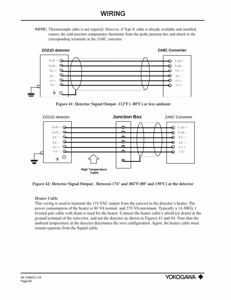
WIRING
IM 11M6A2-YIAPage 60
NOTE: Thermocouple cable is not required. However, if Type K cable is already available and installed,remove the cold junction compensator thermistor from the probe junction box and attach to thecorresponding terminals at the ZA8C converter.
C e ll +
C e l l -
T C +
T C -
C J +
C J -
C el l +
C el l -
T C +
T C -
C J +
C J -
3
4
5
6
7
8
1
2
3
4
5
6
ZO21D detector ZA8C Converter
Figure 41: Detector Signal Output -112ºF ( -80ºC) or less ambient
C e ll +
C e l l -
T C +
T C -
C J +
C J -
C el l +
C el l -
T C +
T C -
C J +
C J -
3
4
5
6
7
8
1
2
3
4
5
6
Junction Box
High Temperature Cable
ZO21D detector ZA8C Converter
Figure 42: Detector Signal Output - Between 176º and 302ºF (80º and 150ºC) at the detector
Heater CableThis wiring is used to transmit the 110 VAC output from the convert to the detectors heater. Thepower consumption of the heater is 80 VA normal, and 270 VA maximum. Typically a 14 AWG, 1twisted pair cable with drain is used for the heater. Connect the heater cables shield (or drain) at theground terminal of the converter, and not the detector as shown in Figures 43 and 44. Note that theambient temperature at the detector determines the wire configuration. Again, the heater cable mustremain separate from the Signal cable.

WIRING
IM 11M6A2-YIAPage 61
Heater
8
7
GND
16
17
32
ZO21D detector ZA8C Converter
Heater Cable: 14 AWG, 1 twisted pair w/separate shield
Figure 43: Detector Heater Output - Maximum 112ºF (80ºC) ambient
Heater Cable: 14 AWG, 1 twisted pair w/separate shield
High Temperature Cable CaseGround
ZA8C Converter
Heater
8
7
GND
16
17
32
ZO21D detector Junction Box
Figure 44: Detector Heater Output - Between 176º and 302ºF (80º and 150ºC) at the detector

WIRING
IM 11M6A2-YIAPage 62
5.1.5 Quick Disconnect Wiring (Optional)
Yokogawa Industrial Automation offers quick disconnect wiring for the detector heater and signalcables. The cable is pre-attached to connectors so that all the User need perform is match theconnectors for the heater (a 3 pin connector) and signal (a 7 pin connector) male and femaleconnectors. During maintenance, detaching the cable at the detector is quick and easy.
REF. AIR INLET-1/8 NPTF
1.7
CAL. GAS INLET-1/8 NPTF
4.7(120)
(42)
1.2 2.1(30) (53)
1.69(42.9)
150 LB ANSI4" FLAT FACE FLANGE
7 AND 3 PIN QUICK DISCONNECTS
Figure 45: Quick Disconnect
5.2 ANALOG OUTPUT WIRING
This wiring is used to transmit the 4 to 20 mA DC or 0 to 20 mA DC output signal to a peripheraldevice, such as a recorder. A 16 AWG cable, 2 conductor with shield is recommended. Maximum loadresistance is 550 ohms.
(+)26
(-)27+-
ZA8C Converter Receiver
Figure 46: Wiring for Analog Output
The terminal screw thread is M4 at the ZA8C converter. Connect the shield of the cable generally onthe side of the device receiving the analog signal, i.e. the recorder as shown in Figure 45. It isimportant to connect the polarities correctly.
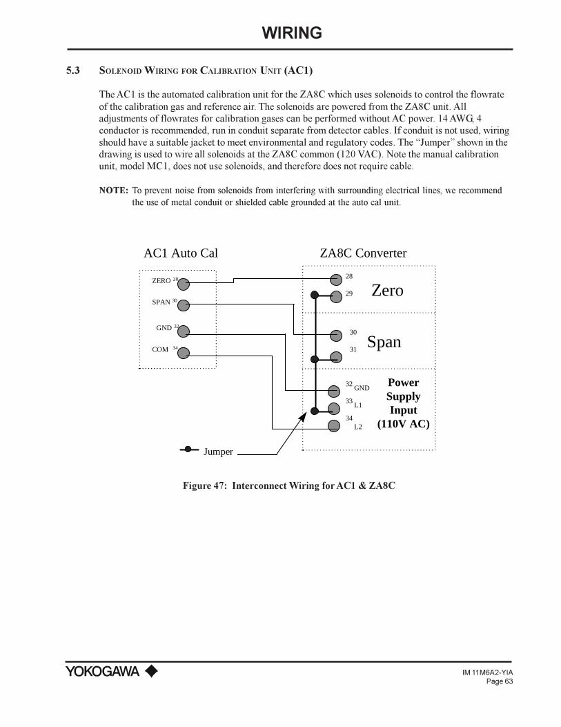
WIRING
IM 11M6A2-YIAPage 63
5.3 SOLENOID WIRING FOR CALIBRATION UNIT (AC1)
The AC1 is the automated calibration unit for the ZA8C which uses solenoids to control the flowrateof the calibration gas and reference air. The solenoids are powered from the ZA8C unit. Alladjustments of flowrates for calibration gases can be performed without AC power. 14 AWG, 4conductor is recommended, run in conduit separate from detector cables. If conduit is not used, wiringshould have a suitable jacket to meet environmental and regulatory codes. The Jumper shown in thedrawing is used to wire all solenoids at the ZA8C common (120 VAC). Note the manual calibrationunit, model MC1, does not use solenoids, and therefore does not require cable.
NOTE: To prevent noise from solenoids from interfering with surrounding electrical lines, we recommendthe use of metal conduit or shielded cable grounded at the auto cal unit.
28
29
30
31
32
33
34
Zero
Span
ZERO 28
SPAN 30
GND 32
COM 34
AC1 Auto Cal ZA8C Converter
PowerSupplyInput
(110V AC)
GND
L1
L2
Jumper
Figure 47: Interconnect Wiring for AC1 & ZA8C

WIRING
IM 11M6A2-YIAPage 64
AC1 Auto Cal ZA8C Converter
28
29
30
31
Zero
Span
ZERO 28
SPAN 30
GND 32
COM 34
32
33
34
32
33
34
GND
L1
L2
Jumper
Power Supply Input220V AC
(Separate Terminal Block)
Figure 48: Interconnect Wiring for 220 V AC ZA8C & AC1
5.4 CONTACT OUTPUT WIRING (OPTIONAL)
The converter can output a maximum of 3 contact signals. The function of the output signals isdetermined from a menu of 13 parameters, as described in the G0 through G3 menu (i.e. low limitalarm or high limit alarm). See Figure 49 for wiring details. Use a cable suitable to safely transmitthe signal based on the following: 30 VDC 2A and 250 VAC 2A. Grouping the conductors into 1 cablejacket is recommended when using multiple contacts, using either a 2, 4, or 8 conductor cable anddividing the signal after the junction box, as shown in Figure 49.
10
11
14
15
Output#1
12
13Output
#2
Output#3
Junction BoxZA8C
Figure 49: Contact Output Wiring
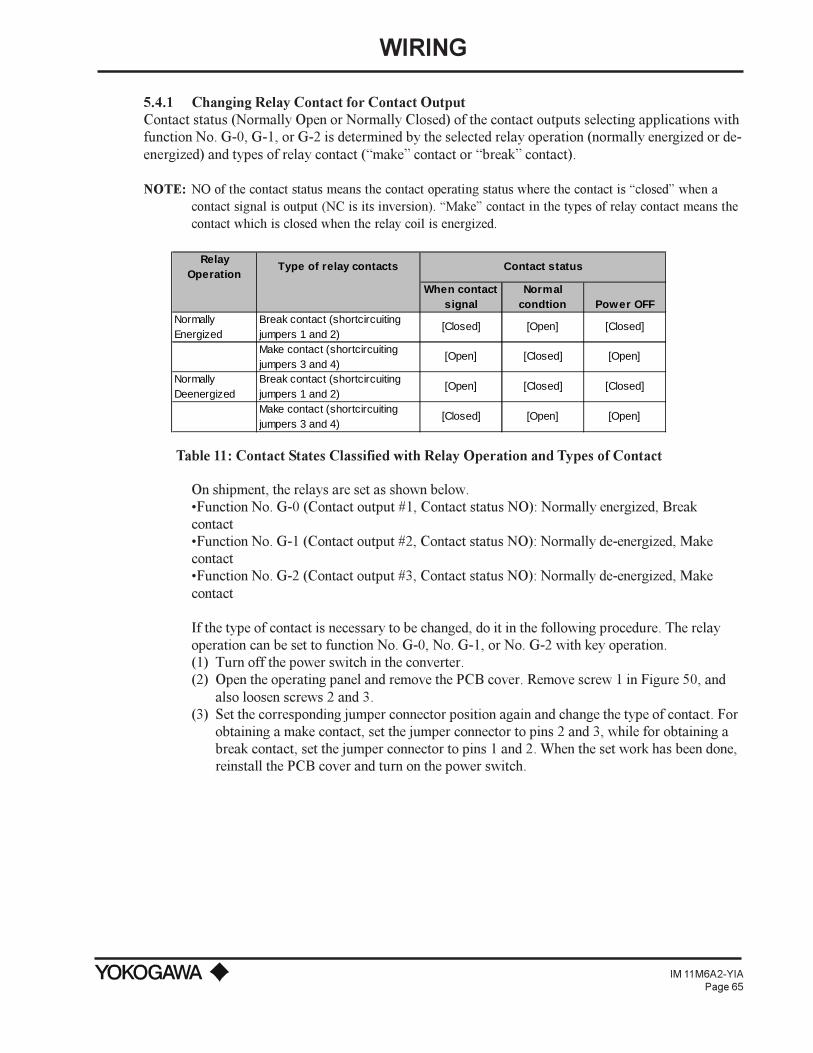
WIRING
IM 11M6A2-YIAPage 65
5.4.1 Changing Relay Contact for Contact OutputContact status (Normally Open or Normally Closed) of the contact outputs selecting applications withfunction No. G-0, G-1, or G-2 is determined by the selected relay operation (normally energized or de-energized) and types of relay contact (make contact or break contact).
NOTE: NO of the contact status means the contact operating status where the contact is closed when acontact signal is output (NC is its inversion). Make contact in the types of relay contact means thecontact which is closed when the relay coil is energized.
Relay Operation
Type of relay contacts Contact status
When contact signal
Normal condtion Power OFF
Normally Energized
Break contact (shortcircuiting jumpers 1 and 2)
[Closed] [Open] [Closed]
Make contact (shortcircuiting jumpers 3 and 4)
[Open] [Closed] [Open]
Normally Deenergized
Break contact (shortcircuiting jumpers 1 and 2)
[Open] [Closed] [Closed]
Make contact (shortcircuiting jumpers 3 and 4)
[Closed] [Open] [Open]
Table 11: Contact States Classified with Relay Operation and Types of Contact
On shipment, the relays are set as shown below.Function No. G-0 (Contact output #1, Contact status NO): Normally energized, BreakcontactFunction No. G-1 (Contact output #2, Contact status NO): Normally de-energized, MakecontactFunction No. G-2 (Contact output #3, Contact status NO): Normally de-energized, Makecontact
If the type of contact is necessary to be changed, do it in the following procedure. The relayoperation can be set to function No. G-0, No. G-1, or No. G-2 with key operation.(1) Turn off the power switch in the converter.(2) Open the operating panel and remove the PCB cover. Remove screw 1 in Figure 50, and
also loosen screws 2 and 3.(3) Set the corresponding jumper connector position again and change the type of contact. For
obtaining a make contact, set the jumper connector to pins 2 and 3, while for obtaining abreak contact, set the jumper connector to pins 1 and 2. When the set work has been done,reinstall the PCB cover and turn on the power switch.

WIRING
IM 11M6A2-YIAPage 66
+ ++++
+++
WIRING TERMINAL BOARD SCREW 2 OPERATION PANEL
SCREW 1
SCREW 3PRINTED CIRCUIT BOARD COVER
SETTING JUMPER CONNECTOR(CN5, CN6, OR CN7)
CN5(FOR RL1)
CN6(FOR RL2)
CN7(FOR RL3)
RELAY RL1(OUTPUT SIGNAL #1)
RELAY RL2(OUTPUT SIGNAL #2)
RELAY RL3(OUTPUT SIGNAL #3)
BREAKCONTACT
MAKECONTACT
123 3
12
MOUNTING POSITION ORJUMPER CONNECTORS(CN5, CN6, OR CN7)
Figure 50: ZA8C Relational Diagram
5.5 CONTACT INPUT WIRING (OPTIONAL)
(+)22
(-)23Input
#1
(+)24
(-)25Input
#2
Junction BoxZA8C (expanded)Converter
Figure 51: Contact Input Wiring
The wiring for the contact inputs is either a 2 conductor cable for use of 1 contact or a 4 conductorcable, for 2 contact inputs. Use a cable suitable to transmit the parameters shown in the table below:
Description ON electrical values OFF electrical valuesResistance (contact) less than 200 ohms greater than 100 k ohmsVoltage -1 to 1 V DC 4.5 to 25 V DC
Table 12: Contact Input ON/OFF Electrical Parameters
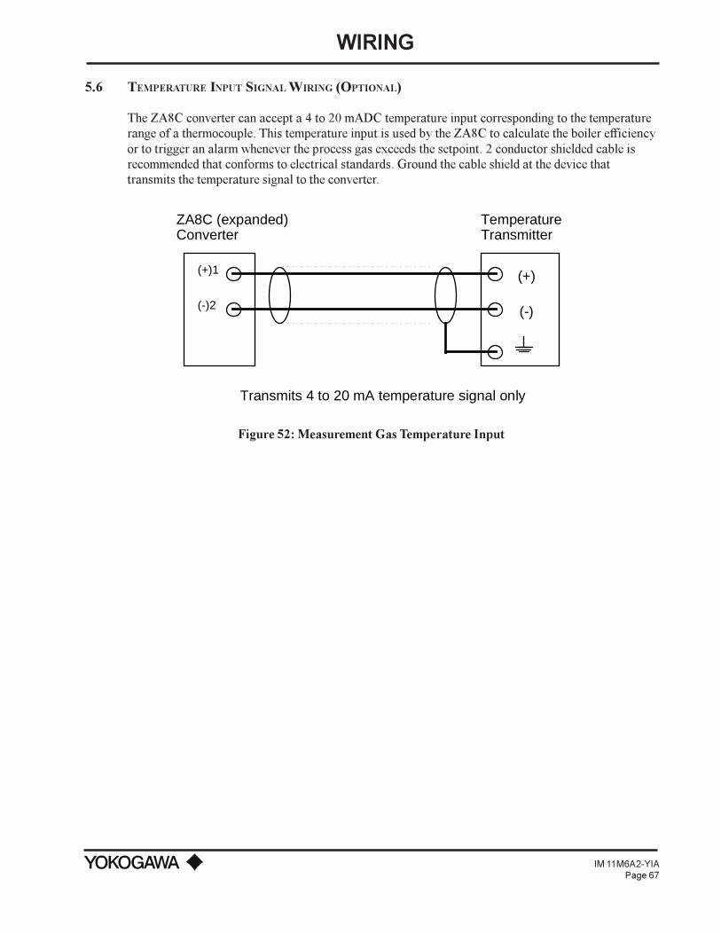
WIRING
IM 11M6A2-YIAPage 67
5.6 TEMPERATURE INPUT SIGNAL WIRING (OPTIONAL)
The ZA8C converter can accept a 4 to 20 mADC temperature input corresponding to the temperaturerange of a thermocouple. This temperature input is used by the ZA8C to calculate the boiler efficiencyor to trigger an alarm whenever the process gas exceeds the setpoint. 2 conductor shielded cable isrecommended that conforms to electrical standards. Ground the cable shield at the device thattransmits the temperature signal to the converter.
(+)1
(-)2
(+)
(-)
ZA8C (expanded)Converter
Temperature Transmitter
Transmits 4 to 20 mA temperature signal only
Figure 52: Measurement Gas Temperature Input

CONFIGURATION
IM 11M6A2-YIAPage 68
VI. PROGRAMMING
In this chapter, the basic operation methods for the ZA8C In-Situ Type Zirconia Oxygen Analyzer aredescribed.
6.1 QUICK START-UP PROGRAMMING FOR ZA8C SINGLE POINT O2 SYSTEM
6.1.1 CONFIGURING THE ZA8C CONVERTERThis is the final stage of the installation of your new Single Point Oxygen measuring system. At thisstage you should have completed the following:Detector InstallationConverter InstallationCalibration Unit InstallationWiring/TubingSetting Flow Rates for Calibration Unit.
If you have not completed any of the above, please do so before proceeding.
Please confirm the following:1) There is a wire connected to all the terminals labeled in white (excluding shields) on the
ZA8C. Open the front panel to perform this quick check. If there is a wire missing on anyone of these “white terminals” then your ZA8C will not function properly (excludinganalog output).
2) Verify that the zirconia cell was removed from its foam package and installed in theZO21D detector.
3) Please record the mix of the calibration gases that you are using as follows:Zero Gas: _________ % vol O
2Span Gas: __21 ___ % vol O
2
NOTE: The span is usually instrument air, which is between 19.0% and 21% vol O2. Also, record the high
and low set point values below.HH: _________ % vol O2 H: _________ % vol O2
LL: _________ % vol O2 L: _________ % vol O2
Record the range of normal operation, and an alternate range:(Normal 4 to 20 mA range) Range 1: _________ % vol O2 to _________ % vol O2
Range 2: _________ % vol O2 to _________ % vol O2
6.1.2 POWER UP ZA8C1) Open the front panel of the ZA8C and turn on the power. This button is located in the
lower left hand corner.2) Close the front panel. Your LED display will flash UUUUU and numbers. The number is
the temperature of the O2 cell in degrees Celsius. The LCD will display “Warming Up.”
Now is the time to begin configuring the ZA8C.
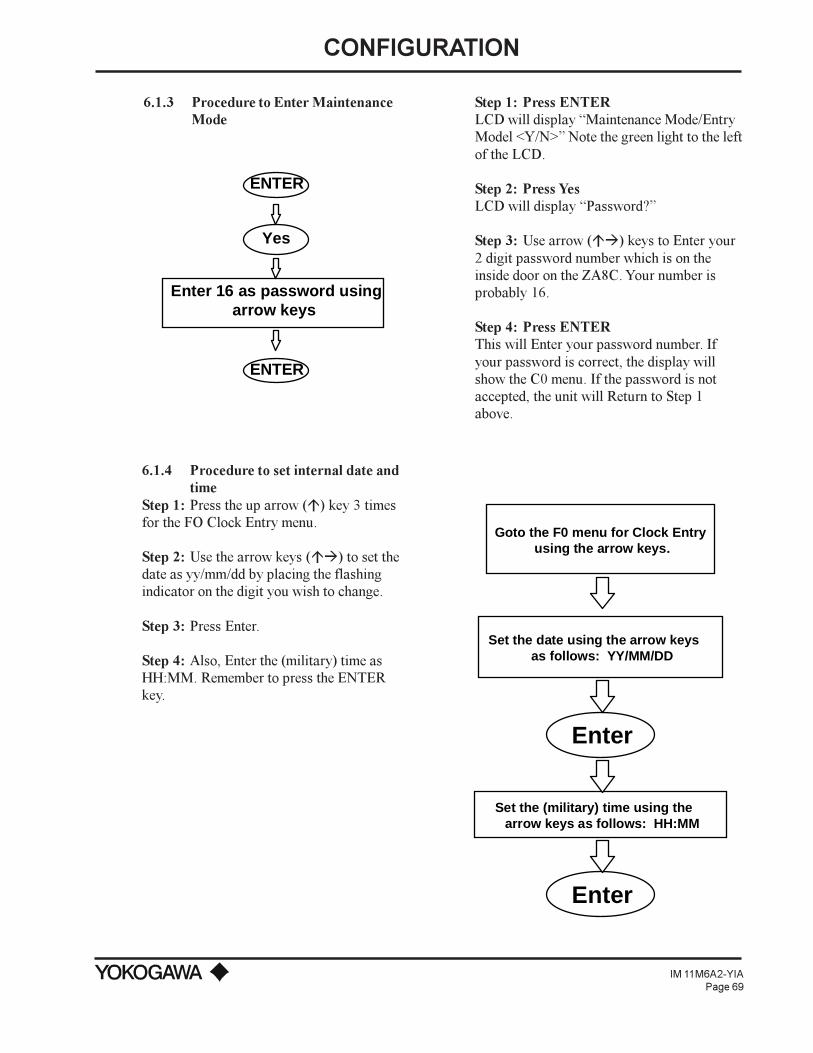
CONFIGURATION
IM 11M6A2-YIAPage 69
6.1.3 Procedure to Enter MaintenanceMode
ENTER
Yes
Enter 16 as password usingarrow keys
ENTER
Step 1: Press ENTERLCD will display Maintenance Mode/EntryModel <Y/N> Note the green light to the leftof the LCD.
Step 2: Press YesLCD will display Password?
Step 3: Use arrow (áà) keys to Enter your2 digit password number which is on theinside door on the ZA8C. Your number isprobably 16.
Step 4: Press ENTERThis will Enter your password number. Ifyour password is correct, the display willshow the C0 menu. If the password is notaccepted, the unit will Return to Step 1above.
6.1.4 Procedure to set internal date andtime
Step 1: Press the up arrow (á) key 3 timesfor the FO Clock Entry menu.
Step 2: Use the arrow keys (áà) to set thedate as yy/mm/dd by placing the flashingindicator on the digit you wish to change.
Step 3: Press Enter.
Step 4: Also, Enter the (military) time asHH:MM. Remember to press the ENTERkey.
Goto the F0 menu for Clock Entry using the arrow keys.
Set the date using the arrow keys as follows: YY/MM/DD
Set the (military) time using the arrow keys as follows: HH:MM
Enter
Enter

CONFIGURATION
IM 11M6A2-YIAPage 70
6.1.5 Procedure to enter calibration gas valuesBegin entering the calibration gas and reference air values from the data that was recorded earlier insection 6.1.1.
Step 1: The flashing cursor must highlight the character you wish to change. To change press uparrow key (á) until the display shows C0, Span Value menu.
Step 2: Normally, if instrument air is used the Span value is between 19% and 21%. Use arrow keys(áà) to enter 21%. Remember to press the ENTER key.
Step 3: Press right arrow (à) key 1 time, then press up arrow key (á) 1 time for the C1, Zero Valuemenu.
Step 4: Use the arrow keys to enter your vol% O2 value for your zero gas cylinder. Remember topress the ENTER key.
Go to C0 menu using arrow keys
Enter Span Gas % vol O2 value.For instrument air, using arrow keys.
Enter
Go to C1 menu using arrow keys
Enter Zero Gas % vol O2 value, using arrow keys. If using instrument air for Span, then max Zero value is 8%.
Enter
Span Set Up Zero Set Up
The following is a list of values that must be programmed in order for the calibration system to workproperly at the ZA8C.
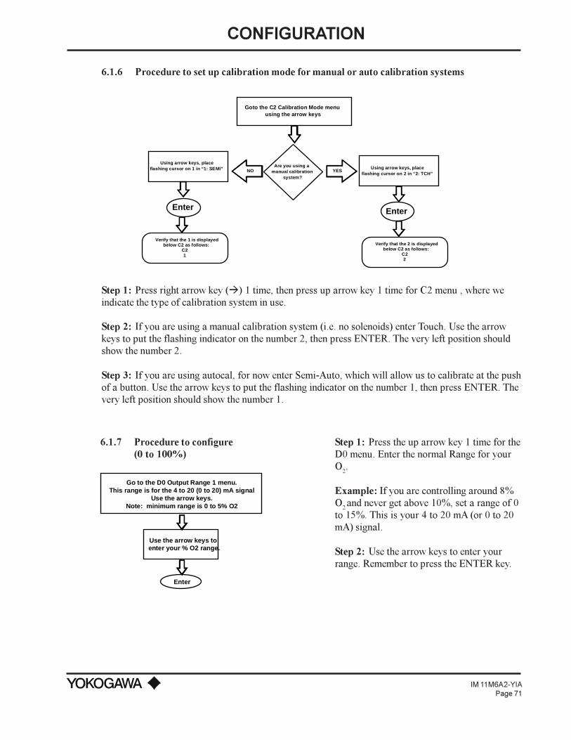
CONFIGURATION
IM 11M6A2-YIAPage 71
6.1.6 Procedure to set up calibration mode for manual or auto calibration systems
Goto the C2 Calibration Mode menuusing the arrow keys
Using arrow keys, placeflashing cursor on 2 in “2: TCH”
Verify that the 2 is displayedbelow C2 as follows:
C22
Enter
Using arrow keys, placeflashing cursor on 1 in “1: SEMI”
Verify that the 1 is displayedbelow C2 as follows:
C21
Enter
Are you using a manual calibration
system?YESNO
Step 1: Press right arrow key (à) 1 time, then press up arrow key 1 time for C2 menu , where weindicate the type of calibration system in use.
Step 2: If you are using a manual calibration system (i.e. no solenoids) enter Touch. Use the arrowkeys to put the flashing indicator on the number 2, then press ENTER. The very left position shouldshow the number 2.
Step 3: If you are using autocal, for now enter Semi-Auto, which will allow us to calibrate at the pushof a button. Use the arrow keys to put the flashing indicator on the number 1, then press ENTER. Thevery left position should show the number 1.
6.1.7 Procedure to configure(0 to 100%)
Go to the D0 Output Range 1 menu.This range is for the 4 to 20 (0 to 20) mA signal
Use the arrow keys.Note: minimum range is 0 to 5% O2
Use the arrow keys to enter your % O2 range.
Enter
Step 1: Press the up arrow key 1 time for theD0 menu. Enter the normal Range for yourO
2.
Example: If you are controlling around 8%O2 and never get above 10%, set a range of 0to 15%. This is your 4 to 20 mA (or 0 to 20mA) signal.
Step 2: Use the arrow keys to enter yourrange. Remember to press the ENTER key.
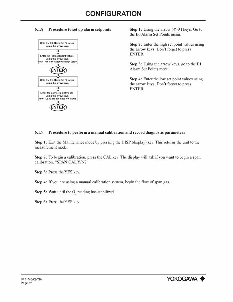
CONFIGURATION
IM 11M6A2-YIAPage 72
6.1.8 Procedure to set up alarm setpoints
Goto the E0 Alarm Set Pt menu using the arrow keys.
Enter the High set point values using the arrow keys.
Note: HH is the absolute high value
ENTER
Goto the E1 Alarm Set Pt menu using the arrow keys.
Enter the Low set point values using the arrow keys.
Note: LL is the absolute low value
ENTER
Step 1: Using the arrow (áà) keys, Go tothe E0 Alarm Set Points menu.
Step 2: Enter the high set point values usingthe arrow keys. Dont forget to pressENTER.
Step 3: Using the arrow keys, go to the E1Alarm Set Points menu.
Step 4: Enter the low set point values usingthe arrow keys. Dont forget to pressENTER.
6.1.9 Procedure to perform a manual calibration and record diagnostic parameters
Step 1: Exit the Maintenance mode by pressing the DISP (display) key. This returns the unit to themeasurement mode.
Step 2: To begin a calibration, press the CAL key. The display will ask if you want to begin a spancalibration, SPAN CAL Y/N?
Step 3: Press the YES key.
Step 4: If you are using a manual calibration system, begin the flow of span gas.
Step 5: Wait until the O2 reading has stabilized.
Step 6: Press the YES key.
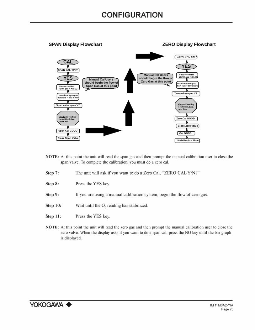
CONFIGURATION
IM 11M6A2-YIAPage 73
YES
SPAN CAL Y/N ?
Please confirmspan gas = X% O2
Introduce span gasflow rate = 600 ml/min
Span valve open Y?
SPAN Display Flowchart ZERO Display Flowchart
ZERO CAL Y/N ?
Please confirmZERO gas = X% O2
Introduce zero gasflow rate = 600 ml/min
Zero valve open Y?
Wait until readingis stabilized,thenenter Yes.
CAL
Manual Cal Usersshould begin the flow ofSpan Gas at this point
Manual Cal Usersshould begin the flow of
Zero Gas at this point
YES
Span Cal GOOD
Wait until readingis stabilized,thenenter Yes.
Zero Cal GOOD
Cal GOOD
Stabilization Time
Close Zero valve
Close Span Valve
NOTE: At this point the unit will read the span gas and then prompt the manual calibration user to close thespan valve. To complete the calibration, you must do a zero cal.
Step 7: The unit will ask if you want to do a Zero Cal, ZERO CAL Y/N?
Step 8: Press the YES key.
Step 9: If you are using a manual calibration system, begin the flow of zero gas.
Step 10: Wait until the O2 reading has stabilized.
Step 11: Press the YES key.
NOTE: At this point the unit will read the zero gas and then prompt the manual calibration user to close thezero valve. When the display asks if you want to do a span cal, press the NO key until the bar graphis displayed.

CONFIGURATION
IM 11M6A2-YIAPage 74
6.1.10 TABLE OF DIAGNOSTIC VALUES
To provide an effective preventive maintenance record of your zirconia cell, it is recommend that theUser keep a log of diagnostic values, which is updated after each two (2) point calibration isperformed. Please note the following:
Cell No. Date of B0 B1 B3 B4 A3Calibration (Span
Correction)(Zero
Correction)(Resistance) (Cell Life) (EMF)
Table 13: Diagnostic Values
The ZA8C converter is a microprocessor based oxygen converter capable of more than the standard 4to 20 mA Analog output. The following provides a brief description of a few features that are standardto the ZA8C converter that the User may want to utilize.
The ZA8C converter allows the User to program two different ranges for the 4 to 20 mA signal. Thisgives the operator a backup for an emergency situation where the unit has surpassed the 20 mAmax. Instead of having the display lockup at 20 mA, the unit will use an alternate, predeterminedRange that is greater than the original setup. In addition, the unit will alert the user with an AnswerBack contact output function, which forces the operator to acknowledge that the Range has changed.Additionally, the User has two low alarm values.

CONFIGURATION
IM 11M6A2-YIAPage 75
SetUp Optional Range 2
Enter
Enter Password #16
Use the arrow keys to goto menu D1 Output Range 2, the alternate range.
Use the arrow keys to enter your % O2 range of measurement.
Enter
Enter
YES
Program Range AnswerbackContact Output
Use the arrow keys to goto menu G0 Contact Output.
Enter the following setup using the arrow keys to change 0 to 1.
01111101100000
Enter
Enter
Enter Password #16
Enter
YES
When a calibration is initiated, you can hold the output value prior to the calibration, or set a presetvalue until the calibration is completed. Should an error occur during calibration, the unit will remainin hold until the cause of the error is eliminated.
Hold Last Measured Value
Use Arrow Keys to goto menu D2 Output Hold
Position Cursor on the 1 in1: HLD
Enter
Enter
Enter Password #16
Enter
YES
Hold Pre-DeterminedValue
Use Arrow Keys to goto menu D2 Output Hold
Position Cursor on the 2 in2: P - Hold
Enter
Use arrow keys to Enter % O2 value to Hold during Calibration
Enter
Enter
Enter Password #16
Enter
YES
The ZA8C has a total of 4 contact outputs, which the User can choose to represent up to 14 differentsituations. We recommend that the User use at least the following conditions for LED alarm contacts:
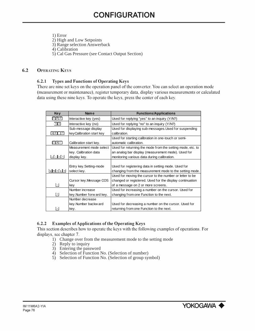
CONFIGURATION
IM 11M6A2-YIAPage 76
1) Error2) High and Low Setpoints3) Range selection Answerback4) Calibration5) Cal Gas Pressure (see Contact Output Section)
6.2 OPERATING KEYS
6.2.1 Types and Functions of Operating KeysThere are nine set keys on the operation panel of the converter. You can select an operation mode(measurement or maintenance), register temporary data, display various measurements or calculateddata using these nine keys. To operate the keys, press the center of each key.
Key Name Functions/Applications
YES Interactive key (yes) Used for replying "yes" to an inquiry (Y/N?)
NO Interactive key (no) Used for replying "no" to an inquiry (Y/N?)
HELP
Sub-message display keyCalibration start key
Used for displaying sub-messages.Used for suspending calibration.
CAL Calibration start key.Used for starting calibration in one-touch or semi-automatic calibration.
DISP
Measurement mode select key. Calibration data display key.
Used for returning the mode from the setting mode, etc. to an analog bar display (measurement mode). Used for monitoring various data during calibration.
ENTER
Entry key.Setting-mode select key.
Used for registering data in setting mode. Used for changing from the measurement mode to the setting mode.
>
Cursor key.Message COS key
Used for moving the cursor to the number or letter to be changed or registered. Used for the display continuation of a message on 2 or more screens.
^
Number increase key.Number forw ard key.
Used for increasing a number on the cursor. Used for changing from one Function to the next.
>
Number decrease key.Number backw ard key.
Used for decreasing a number on the cursor. Used for returning from one Function to the next.
6.2.2 Examples of Applications of the Operating KeysThis section describes how to operate the keys with the following examples of operations. Fordisplays, see chapter 7.
1) Change over from the measurement mode to the setting mode2) Reply to inquiry3) Entering the password4) Selection of Function No. (Selection of number)5) Selection of Function No. (Selection of group symbol)
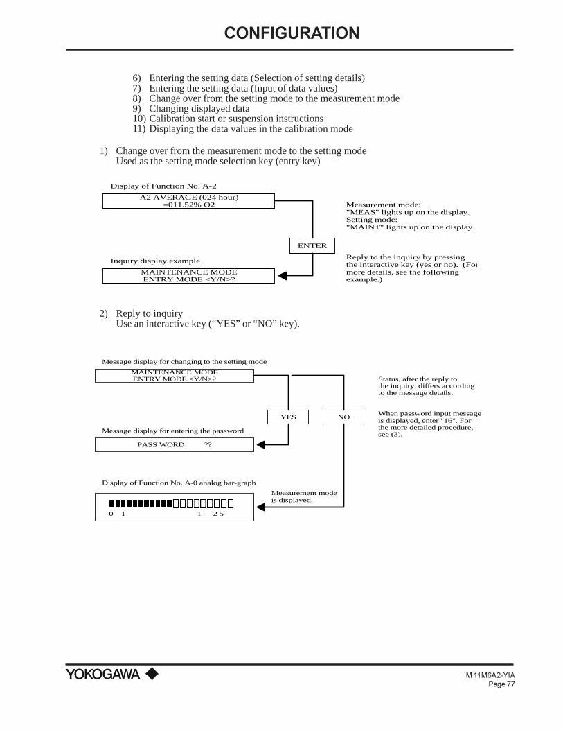
CONFIGURATION
IM 11M6A2-YIAPage 77
6) Entering the setting data (Selection of setting details)7) Entering the setting data (Input of data values)8) Change over from the setting mode to the measurement mode9) Changing displayed data10) Calibration start or suspension instructions11) Displaying the data values in the calibration mode
1) Change over from the measurement mode to the setting modeUsed as the setting mode selection key (entry key)
MAINTENANCE MODEENTRY MODE <Y/N>?
A2 AVERAGE (024 hour)=011.52% O2
Display of Function No. A-2
Inquiry display example
ENTER
Measurement mode:"MEAS" lights up on the display.Setting mode:"MAINT" lights up on the display.
Reply to the inquiry by pressingthe interactive key (yes or no). (Formore details, see the following example.)
2) Reply to inquiryUse an interactive key (“YES” or “NO” key).
MAINTENANCE MODEENTRY MODE <Y/N>?
nnnnnnnnnnnooooooooo0 1 1 2 5
YES NO
PASS WORD ??
Message display for changing to the setting mode
Message display for entering the password
Display of Function No. A-0 analog bar-graph
Status, after the reply to the inquiry, differs accordingto the message details.
When password input message is displayed, enter "16". Forthe more detailed procedure,see (3).
Measurement mode is displayed.

CONFIGURATION
IM 11M6A2-YIAPage 78
3) Entering the password (16)To assign a function in the setting mode, enter the password. The password is “16”, as shown onthe label attached to the inside door of the ZA8C. To do so, use the number increase/decrease key,cursor movement key, and the entry key. The flashing indicator is positioned on the item that canbe changed with the arrow keys.
ENTER
À
Á
Á ÂCO CAL GAS CONC (%O2)
SPAN = 021.00
(Two times)
Cursor moves to "?"on the right side.
Press ENTER after "16" is displayed.
The first Function No. in the setting mode is displayed.
Display of Function No., C-0
Display of password - entering message
1
?PASS WORD ?
PASS WORD ?
PASS WORD 1 ?

CONFIGURATION
IM 11M6A2-YIAPage 79
4) Selection of the Function No. (selection of number)The number increase key, number decrease key and the cursor key are used. The commonly usedfunctions are silk-screened on the front of the ZA8C converter for easy operation without aninstruction manual. However, the programming of the contact inputs and outputs, along with theefficiency parameters are only found in this manual.
Â
Á
Á
À
À DISP
À
nnnnnnnnnnnooooooooo0 1 1 2 5
C1 CAL GAS CONC (% O2)ZERO = 001.00
CO CAL GAS CONC (% O2)SPAN = 021.00
Display of Function No., C-0
No. decreases.
No. increases.
Number is changed from 0 to 1.
Cursor moves overto the next number.
Data-entering status is effected.
The mode changes to the measurement mode and displays an analog bar-graph.
(Note 1) If the entry key "ENTER" is pressed when the cursor resides in a function No. position,note that "0:AT (automatic calibration)" is automatically set as the calibration mode.
O CAL GAS CONC (% O2)SPAN = 021.00
C
C CAL GAS CONC (% O2)SPAN = 021.00
0
(Note 1)
2C CALIBRATION MODE 0: AT 1:SEM1 2:TCH
C CAL GAS CONC (% O2)ZERO = 001.00
1
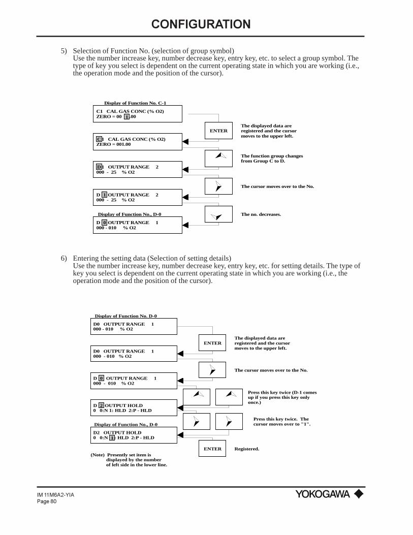
CONFIGURATION
IM 11M6A2-YIAPage 80
5) Selection of Function No. (selection of group symbol)Use the number increase key, number decrease key, entry key, etc. to select a group symbol. Thetype of key you select is dependent on the current operating state in which you are working (i.e.,the operation mode and the position of the cursor).
Display of Function No., D-0
ENTER
Á
À
Â
The displayed data are registered and the cursormoves to the upper left.
The function group changes from Group C to D.
The cursor moves over to the No.
The no. decreases.
Display of Function No. C-1
C1 CAL GAS CONC (% O2)ZERO = 00 .00
1 CAL GAS CONC (% O2)ZERO = 001.00C
D 1 OUTPUT RANGE 2000 - 25 % O2
1D OUTPUT RANGE 2000 - 25 % O2
0D OUTPUT RANGE 1000 - 010 % O2
1
6) Entering the setting data (Selection of setting details)Use the number increase key, number decrease key, entry key, etc. for setting details. The type ofkey you select is dependent on the current operating state in which you are working (i.e., theoperation mode and the position of the cursor).
Display of Function No., D-0
ENTERThe displayed data are registered and the cursormoves to the upper left.
Display of Function No. D-0
The cursor moves over to the No.À
Press this key twice. Thecursor moves over to "1".
Á Á
À À
ENTER Registered.(Note) Presently set item is displayed by the number of left side in the lower line.
Press this key twice (D-1 comes up if you press this key only once.)
D0 OUTPUT RANGE 1000 - 010 % O2
D0 OUTPUT RANGE 1000 - 010 % O2
D OUTPUT RANGE 1000 - 010 % O2
D OUTPUT HOLD0 0:N 1: HLD 2:P - HLD
0
2
D2 OUTPUT HOLD0 0:N : HLD 2:P - HLD1
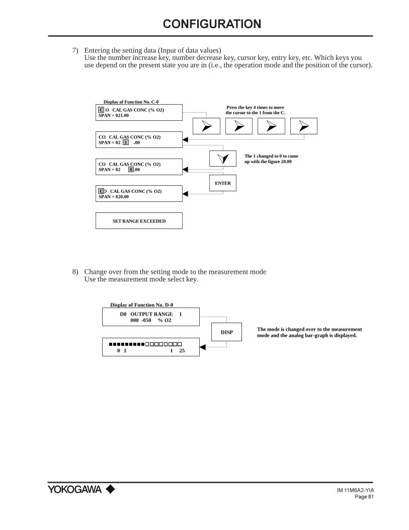
CONFIGURATION
IM 11M6A2-YIAPage 81
7) Entering the setting data (Input of data values)Use the number increase key, number decrease key, cursor key, entry key, etc. Which keys youuse depend on the present state you are in (i.e., the operation mode and the position of the cursor).
Display of Function No. C-0
SET RANGE EXCEEDED
À À À À
ÂENTER
Press the key 4 times to movethe cursor to the 1 from the C.
The 1 changed to 0 to come up with the figure 20.00
O CAL GAS CONC (% O2)SPAN = 020.00C
1CO CAL GAS CONC (% O2)SPAN = 02 .00
CO CAL GAS CONC (% O2)SPAN = 02 .000
O CAL GAS CONC (% O2)SPAN = 021.00C
8) Change over from the setting mode to the measurement modeUse the measurement mode select key.
Display of Function No. D-0
DISP
D0 OUTPUT RANGE 1000 -050 % O2
The mode is changed over to the measurementmode and the analog bar-graph is displayed.
0 1 1 25nnnnnnnnnoooooooo

CONFIGURATION
IM 11M6A2-YIAPage 82
9) Changing displayed dataUse the number increase key to change the function number. Use the cursor key to change toanother function group or to move to the next screen.
Display of Function No. A-0
0 1 1 25
A7 EXCESS AIR RATIO= 01.40
B0 SPAN (0) = 099.7 %89/04/26 14:30 H
Á Á
À The display changes fromGroup A to Group B.
nnnnnnnnnnnooooooooo
When there are 2 or more component screens, H shows in the lower, right position. Thesecond (or next) screen can be displayed bypressing the HELP key.
10) Calibration start or suspension instructionsUse the calibration start or suspension key. For more details on the calibration keys, see chapterIX.
Display of Function No. A-0
CALIBRATION Y ?
CALIBRATION Y ?
CAL
DISP NO YESHELP
HELP
The mode changes from the measurementmode to the calibration mode.
Upon pressing the key, the solenoidvalve in the calibration gas line isclosed. After the stability time asset in Function No. C-4 elapses,the mode changes back to themeasurement mode.
If changing another display in the measurement mode to an analog bar-graph, press [DISP] key.
SPAN CAL ON
ZERO CAL ON
0 1 1 25nnnnnnnnnnnooooooooo
0 1 1 250 1 1 25nnnnnnnnnnnooooooooo
0 1 1 25nnnnnnnnnnnooooooooo
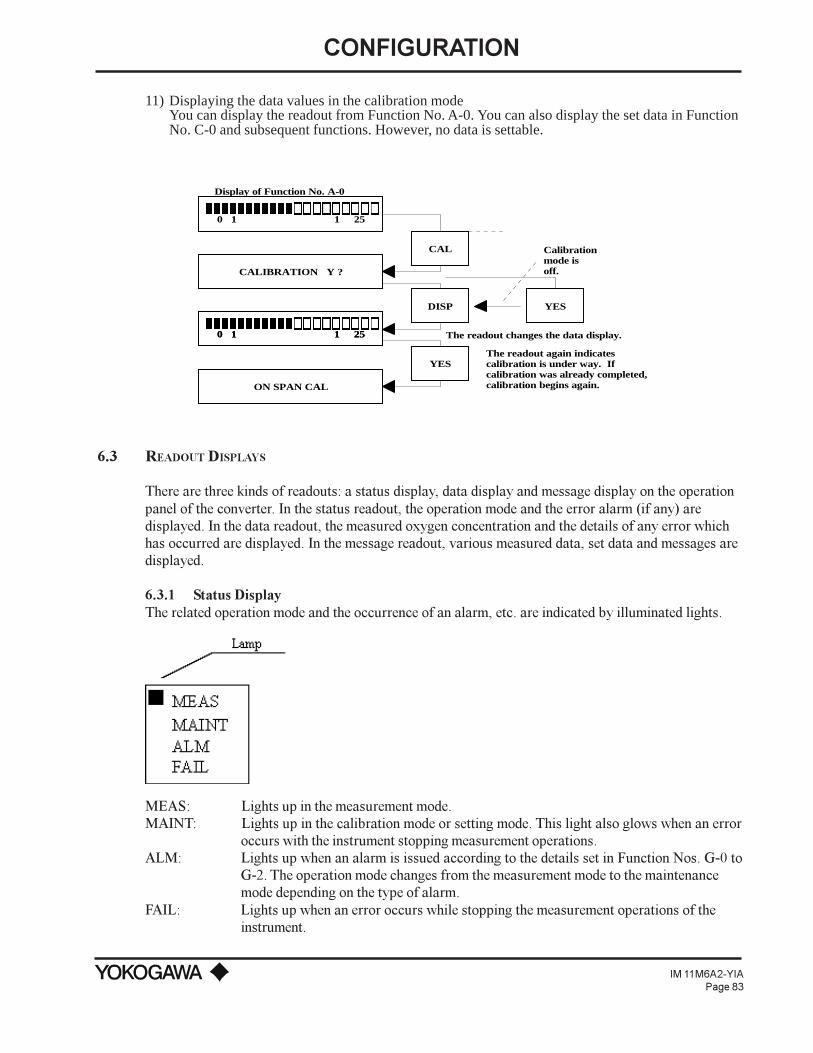
CONFIGURATION
IM 11M6A2-YIAPage 83
11) Displaying the data values in the calibration modeYou can display the readout from Function No. A-0. You can also display the set data in FunctionNo. C-0 and subsequent functions. However, no data is settable.
Display of Function No. A-0
0 1 1 25
0 1 1 25
CALIBRATION Y ?
0 1 1 25
DISP
ON SPAN CAL
YES
YES
Calibrationmode isoff.
The readout changes the data display.
The readout again indicatescalibration is under way. Ifcalibration was already completed,calibration begins again.
CAL
nnnnnnnnnnnooooooooo
nnnnnnnnnnnooooooooo
6.3 READOUT DISPLAYS
There are three kinds of readouts: a status display, data display and message display on the operationpanel of the converter. In the status readout, the operation mode and the error alarm (if any) aredisplayed. In the data readout, the measured oxygen concentration and the details of any error whichhas occurred are displayed. In the message readout, various measured data, set data and messages aredisplayed.
6.3.1 Status DisplayThe related operation mode and the occurrence of an alarm, etc. are indicated by illuminated lights.
MEAS: Lights up in the measurement mode.MAINT: Lights up in the calibration mode or setting mode. This light also glows when an error
occurs with the instrument stopping measurement operations.ALM: Lights up when an alarm is issued according to the details set in Function Nos. G-0 to
G-2. The operation mode changes from the measurement mode to the maintenancemode depending on the type of alarm.
FAIL: Lights up when an error occurs while stopping the measurement operations of theinstrument.

CONFIGURATION
IM 11M6A2-YIAPage 84
6.3.2 Data DisplayThis display incorporates a large 4-digit LED. Items displayed here are the warm-up state (warm-upsymbol ON and the current temperature of the sensor), measured oxygen concentration (vol% O2) andthe error code. Normally, just the measured oxygen concentration is displayed.
Example of warm-up state display
XXXX Alternately displayed
Current temperature of sensor in ºC
Example of measured oxygen concentration display
NOTE: Measured value is displayed. Thus, even if "1" (oxygen concentration in dry gas) is selected in
function No. D-6, indication in the data display is the oxygen concentration in wet gas.
Example of error occurrence display
(NOTE: An error display "E--5", "E--6" or "E--7" generated in calibration is indicated alternately with the
oxygen concentration display.
6.3.3 Message DisplayThe message display incorporates the dot matrix LCD of 40 characters (20 characters x two lines).This readout displays the following messages:
To display the message of a value-setting group, you have to enter the specified password. Thepassword is the 2-digit number 16.
1) Measurement value group A (Function No. A-0 - A-7)2) Measurement value group B (Function No. B-0 - B-8)3) Value-setting group C (Function No. C-0 - C-7)4) Value-setting group D (Function No. D-0 - D-6)5) Value-setting group E (Function No. E-0 - E-2)6) Value-setting group F (Function No. F-0 - F-5)7) Value-setting group G (Function No. G-0 - G-4)8) Value-setting group H (Function No. H-0 - H-1)9) Value-setting group J (Function No. J-0 - J-7)10) Status message group11) Interactive message group12) Sub-message group
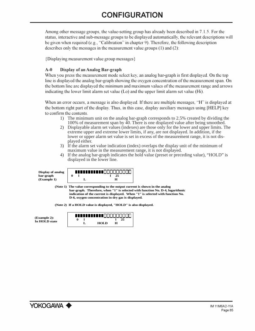
CONFIGURATION
IM 11M6A2-YIAPage 85
Among other message groups, the value-setting group has already been described in 7.1.5. For thestatus, interactive and sub-message groups to be displayed automatically, the relevant descriptions willbe given when required (e.g., Calibration in chapter 9). Therefore, the following descriptiondescribes only the messages in the measurement value groups (1) and (2):
Displaying measurement value group messages
A-0 Display of an Analog Bar-graphWhen you press the measurement mode select key, an analog bar-graph is first displayed. On the topline is displayed the analog bar-graph showing the oxygen concentration of the measurement span. Onthe bottom line are displayed the minimum and maximum values of the measurement range and arrowsindicating the lower limit alarm set value (Lo) and the upper limit alarm set value (Hi).
When an error occurs, a message is also displayed. If there are multiple messages, H is displayed atthe bottom right part of the display. Thus, in this case, display auxiliary messages using [HELP] keyto confirm the contents.
1) The minimum unit on the analog bar-graph corresponds to 2.5% created by dividing the100% of measurement span by 40. There is one displayed value after being smoothed.
2) Displayable alarm set values (indexes) are those only for the lower and upper limits. Theextreme upper and extreme lower limits, if any, are not displayed. In addition, if thelower or upper alarm set value is set in excess of the measurement range, it is not dis-played either.
3) If the alarm set value indication (index) overlaps the display unit of the minimum ofmaximum value in the measurement range, it is not displayed.
4) If the analog bar-graph indicates the hold value (preset or preceding value), “HOLD” isdisplayed in the lower line.
nnnnnnnnnnnooooooooonnnnnnnnnnnooooooooo
nnnnnnnnnnnooooooooo
(Note 1) The value corresponding to the output current is shown in the analog bar-graph. Therefore, when "1" is selected with function No. D-4, logarithmic indication of the current is displayed. When "1" is selected with function No. D-6, oxygen concentration in dry gas is displayed.
(Note 2) If a HOLD value is displayed, "HOLD" is also displayed.
(Example 2):In HOLD state
Display of analog bar-graph(Example 1)
0 l l 25 L H
0 l l 25L HOLD H

CONFIGURATION
IM 11M6A2-YIAPage 86
POOR or NC in OUTLNECELL BRKN or DMGD H
PLS READ INST MANUAL"TROUBLESHOOTING"
When more than one error occurs, "H" is displayed.Sequentially transfer the display using the auxiliarymessage display key.
CELL FAILURE - CAUSE?INCOR WRG (CONV > DET) H
*Error Code "E---2"
PLS READ INST MANUAL"TROUBLESHOOTING"
Display when an error occurs (Example 1)
Display when an error occurs (Example 2)
TEMP TOO LO - CAUSE?INCOR or BRKN WRG H
CLDJCT CKT, e + c - ABNLHTR or TC LNE BRKN H
PLS READ INST MANUAL"TROUBLESHOOTING"
BLWN FU or POOR CONTSHORT in TC H

CONFIGURATION
IM 11M6A2-YIAPage 87
*Error Code "E---3"
PLS READ INST MANUAL"TROUBLESHOOTING"
Display when an error occurs (Example 3)
PLS READ INST MANUAL"TROUBLESHOOTING"
*Error Code "E---4"
Display when an error occurs (Example 4)
*Error Code "E---5"
Display when an error occurs (Example 5)
*Error Code "E---6"
Display when an error occurs (Example 6)
TEMP TOO HI - CAUSE?INCOR or BRKN WRG H
CLDJCT CKT, e + c - ABNLHTR or TC LNE BRKN H
BLWN FU or POOR CONTSHORT in TC H
ANALOG CKT FAILUREAD CONV DEFECTIVE H
CUST RPR IMPOSSIBLECONT JYC SVCE DEPT
CAL VAL ABNL ( 0 PT )CAUSE? CELL DMGD H
CAL GAS FLTR < IND ’ DPOSSIBLE LEAK H
WRNG GAS - CHNG SPAN --> 0DIFF CONC & MEM VAL H
CAL VAL ABNL - SPAN PTCAUSE ? CELL DMGD H
CAL GAS FLTR < IND ’ DPOSSIBLE LEAK H
WRNG GAS - CHNG 0 --> SPANDIFF CONC & MEM VAL H
PLS READ INST MANUAL"TROUBLESHOOTING"
YIA
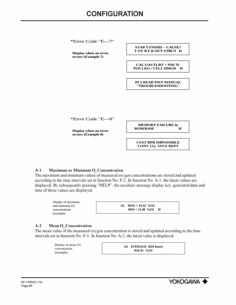
CONFIGURATION
IM 11M6A2-YIAPage 88
*Error Code "E---7"
Display when an error occurs (Example 7)
STAB T FNSHD -- CAUSE?T OV B F R OUT STBLN H
CAL GAS FLRT < IND ’D POS LKG / CELL DMGD H
PLS READ INST MANUAL"TROUBLESHOOTING"
Display when an error occurs (Example 8)
*Error Code "E---8"
MEMORY FAILURE inROM/RAM H
CUST RPR IMPOSSIBLECONT JYC SVCE DEPT
A-1 Maximum or Minimum O2 ConcentrationThe maximum and minimum values of measured oxygen concentrations are stored and updatedaccording to the time intervals set in function No. F-2. In function No. A-1, the latest values aredisplayed. By subsequently pressing HELP, the auxiliary message display key, generated data andtime of those values are displayed.
Display of maximum and minimum O2 concentrations (example)
A1 MAX = 19.32 %O2 MIN = 15.48 %O2 H
A-2 Mean O2 Concentration
The mean value of the measured oxygen concentration is stored and updated according to the timeintervals set in function No. F-1. In function No. A-2, the latest value is displayed.
A2 AVERAGE (024 hour)016.92 %O2
Display of mean O2 concentration(example)
YIA

CONFIGURATION
IM 11M6A2-YIAPage 89
A-3 Cell VoltageCell (sensor) voltage is an index for noting the deterioration of the sensor. In function No. A-3, the cellvoltage at the oxygen concentration presently measured is displayed. The sensor is judged to benormal if the measured value agrees with the theoretical value at the same oxygen concentration.
E= -50.74 log (Px /Pa) [mV]Where Px: O
2 concentration in the measurement gas
Pa: O2 concentration in the comparison gas (21 vol% O
2)
% O2
mV
0.1
117.83
0.2
102.56
0.3
93.62
0.4
87.28
0.5
82.36
0.6
78.35
0.7
74.95
0.8
72.01
0.9
69.41
% O2
mV
10
16.35
21.0
0
30
-7.86
40
-14.2
50
-19.2
60
-23.1
70
-26.5
80
-29.5
90
-32.1
% O2
mV
1
67.09
2
51.82
3
42.88
4
36.54
5
31.62
6
27.61
7
24.21
8
21.27
9
18.67
% O2
mV
100
-34.4
Figure 53: Oxygen Concentration, Vol% O2 vs Cell Voltage mV (Cell temperature 750º C)
A3 CELL EMF = 018.3 mVDisplay of cellvoltage (example)
A-4 Cell Temperature/Thermocouple VoltageCell temperature is measured using a type K (chromel-alumel) thermocouple. The cold junction of thisthermocouple is located at the terminal end of the detector. The temperature at this cold junction ismeasured with a transistor. In function No. A-4, displayed is a voltage affected by the temperature atthe cold junction terminal.
If the cell temperature is higher than 780º C (1436º F), error E3 is effected, while error E2 isdisplayed at 730º C (1346º F) or less.
NOTE: When the cell temperature is to be determined based on the displayed voltage, compensate forvoltage error due to the temperature at the cold junction.
A4 CELL TEMP = 0750ºC TC (K) EMF = 030.4 mV
Display of cell temperature/thermocouple voltage(example)
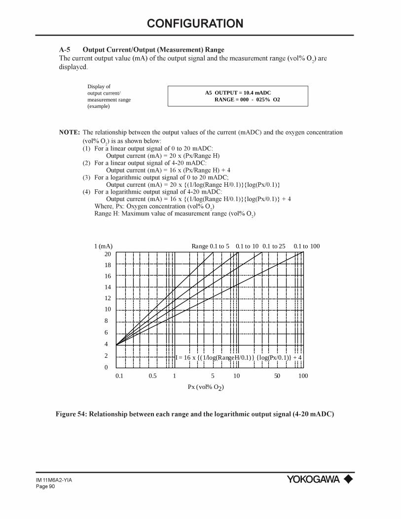
CONFIGURATION
IM 11M6A2-YIAPage 90
A-5 Output Current/Output (Measurement) RangeThe current output value (mA) of the output signal and the measurement range (vol% O
2) are
displayed.
A5 OUTPUT = 10.4 mADC RANGE = 000 - 025% O2
Display of output current/measurement range(example)
NOTE: The relationship between the output values of the current (mADC) and the oxygen concentration(vol% O
2) is as shown below:
(1) For a linear output signal of 0 to 20 mADC:Output current (mA) = 20 x (Px/Range H)
(2) For a linear output signal of 4-20 mADC:Output current (mA) = 16 x (Px/Range H) + 4
(3) For a logarithmic output signal of 0 to 20 mADC;Output current (mA) = 20 x (1/log(Range H/0.1)log(Px/0.1)
(4) For a logarithmic output signal of 4-20 mADC:Output current (mA) = 16 x (1/log(Range H/0.1)log(Px/0.1) + 4
Where, Px: Oxygen concentration (vol% O2)
Range H: Maximum value of measurement range (vol% O2)
0.1
20
18
16
14
12
10
8
6
4
2
010.5 5 10 10050
0.1 to 1000.1 to 250.1 to 10Range 0.1 to 51 (mA)
I = 16 x (1/log(RangeH/0.1) log(Px/0.1) + 4
Px (vol% O2)
Figure 54: Relationship between each range and the logarithmic output signal (4-20 mADC)

CONFIGURATION
IM 11M6A2-YIAPage 91
A-6 TimeThe time is displayed by the clock function of the converter (Year, Month, Day, Hour, Minute). Ifcorrection of this time is required, enter the correct time in Function No. F-0.
A6 PRESENT TIME 90/05/26 13:00
Display of time(example)
NOTE: Clock function must be reset when power is removed from the analyzer.
A-7 Air RatioThe current air ratio, obtained by calculation, is displayed. If you use this air ratio data for estimatingthe combustion efficiency, etc., check that there is no air leaking in beforehand and that the measuredvalue has not been affected by any interference gas (CH4, CO, H2, etc.)
Air ratio m is calculated by the following formula:m=1/(21-Oxygen concentration) x 21
A7 EXCESS AIR RATIO03.59
Display of air ratio(example)
NOTE: A-7 is the last message in the measured value group A. If you want to display messages in measuredvalue group B, press the cursor > key.
B-0 Span Point Correction Ratio RecordThe span point correction ratio, obtained every time the span point is calibrated, is displayed. You candetermine the degree of deterioration in the cell (sensor) from this value. You can display the datarecord for the previous ten times including the latest data. To display each datum on the screen, call upthe next screen by pressing the message HELP key. You can have the span point correction ratio asfollows: Color the correctable range of the span point is 0 ±18% (corresponding to a voltage at a spanpoint of about ±15 mV).
Zero origin
A
B
Span originC0
es
e1
p120.6(Span gasconcentration)
p2(Zero gasconcentration)
0.51
Corrected (theoretical)calibration curve
Calibration curvebefore correction
e2
ez
81.92
Cell voltagemV
Figure 55: Span Point Correction Ratio

CONFIGURATION
IM 11M6A2-YIAPage 92
Zero point correction factor = (B/A) x 100 (%) Correctable range: 100 ±30%Span point correction factor = (C/A) x 100 (%) Correctable range: 0 ±18%
B0 SPAN (0) = 001.5% 89/04/30 09:30 H
Display of the spanpoint correction ratiorecord (1) (example)
B-1 Zero Point Correction Ratio RecordThe zero point correction ratio, obtained every time the zero point is calibrated, is displayed. You candetermine the degree of cell (sensor) deterioration from this value. You can display the data record forthe previous ten times including the latest data. To display each data display screen, call up the nextscreen by pressing the message “HELP” key. You can get the zero point correction ratio by the methodin Figure 54. The correctable range for the zero point is 100 ±30%.
B1 ZERO (0 = 098.7% 89/04/30 09:30 H
Display of the zeropoint correction ratiorecord (1) (example)
B-2 Response TimeResponse time, displayed in function No. B-2, can be obtained during calibration by the method inFigure 55.
NOTE: If the zero point or the span point is skipped, it is not executed as in the one-touch calibration mode.
Figure 56: Calculation of response time
Response time is calculated after the corrected calibration curve is obtained. With a starting pointwhere a voltage corresponding to 10% of the corrected calibration curve span is found, the time that ittakes for the voltage to reach the 90% mark of a 100% voltage corresponding to the oxygenconcentration of a calibration gas (zero gas) set in the converter is calculated. In other words, theresponse time for the above is in the range from 10 to 90%.

CONFIGURATION
IM 11M6A2-YIAPage 93
B2 CELL RESPOINSE (10 - 90%) = 003 SEC
Display of responsetime (example)
B-3 Resistance in the CellA new cell (sensor) has an internal resistance of less than 200Ω. The resistance increases as the celldeteriorates. Therefore, the internal resistance of a cell is an index for indicating the degree of thesensor deterioration. In function No. B-3, the value obtained at the most recent calibration isdisplayed.
B3 CELL RESISTANCE00175 OHM
Display of inner resistance of cell(example)
B-4 Robustness of the CellThe robustness of the cell, an index for estimating the remaining life of the cell (sensor) is classifiedby a number from five (good) to one (poor). This robustness is determined after comprehensivelyevaluating various data monitored during calibration (e.g., the response time, the internal resistance ofthe cell, and the calibration coefficient.). However, when the zero point or span is skipped, no responsetime is measurable. Thus, cell robustness is obtained from the other evaluation items.
B4 SELL ROBUSTNESS (5)LIFE > 12 MONTH
Display of cell robustness(example)
B-5 Temperature at the Cold Junction on a ThermocoupleThe temperature at the cold junction terminal, measured with a transistor, is displayed. The highestpermissible temperature of the terminal is 80º C (176º F). If this temperature is exceeded, it must belowered by shielding the detector terminal box from radiation heat, etc.
B5 CJ TEMP = 026ºC
Display of thetemperature at the coldjunction on a thermocouple (example)
B-6 Heater ON Time RatioThe sensor in the detector is heated up to and maintained at a temperature of 750º C (1382º F) by theheater. The higher the temperature of the measurement gas, the less the ON time of the heaterbecomes. However, if this time becomes too short, the temperature of the measurement gas mightexceed the limit temperature of 600º C (1100º F), which is not recommended for the detector. Theheater ON time ratio is an index for monitoring an abnormal temperature rise in the measurement gas.However, its critical temperature rise varies depending on the conditions in individual processes.Therefore, no definite specifications are given herein; however, a general guideline is about 20 to 30%.
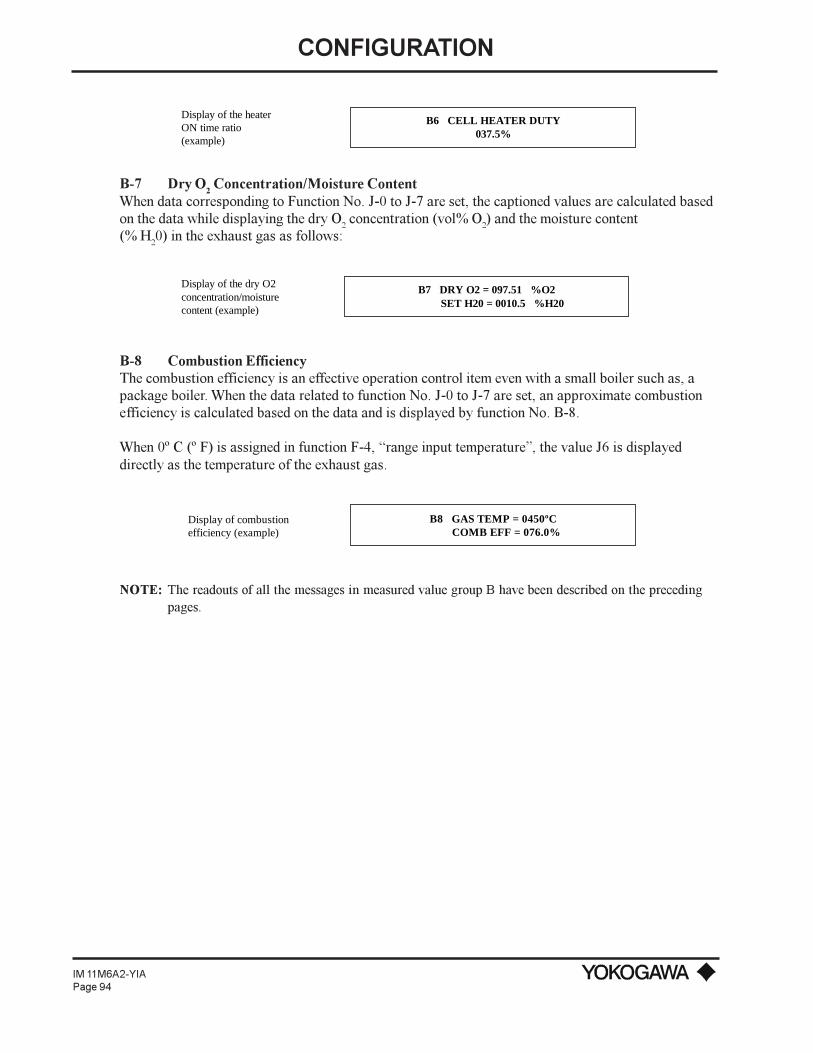
CONFIGURATION
IM 11M6A2-YIAPage 94
B6 CELL HEATER DUTY037.5%
Display of the heaterON time ratio(example)
B-7 Dry O2 Concentration/Moisture Content
When data corresponding to Function No. J-0 to J-7 are set, the captioned values are calculated basedon the data while displaying the dry O2 concentration (vol% O2) and the moisture content(% H20) in the exhaust gas as follows:
B7 DRY O2 = 097.51 %O2 SET H20 = 0010.5 %H20
Display of the dry O2 concentration/moisturecontent (example)
B-8 Combustion EfficiencyThe combustion efficiency is an effective operation control item even with a small boiler such as, apackage boiler. When the data related to function No. J-0 to J-7 are set, an approximate combustionefficiency is calculated based on the data and is displayed by function No. B-8.
When 0º C (º F) is assigned in function F-4, range input temperature, the value J6 is displayeddirectly as the temperature of the exhaust gas.
B8 GAS TEMP = 0450ºC COMB EFF = 076.0%
Display of combustion efficiency (example)
NOTE: The readouts of all the messages in measured value group B have been described on the precedingpages.
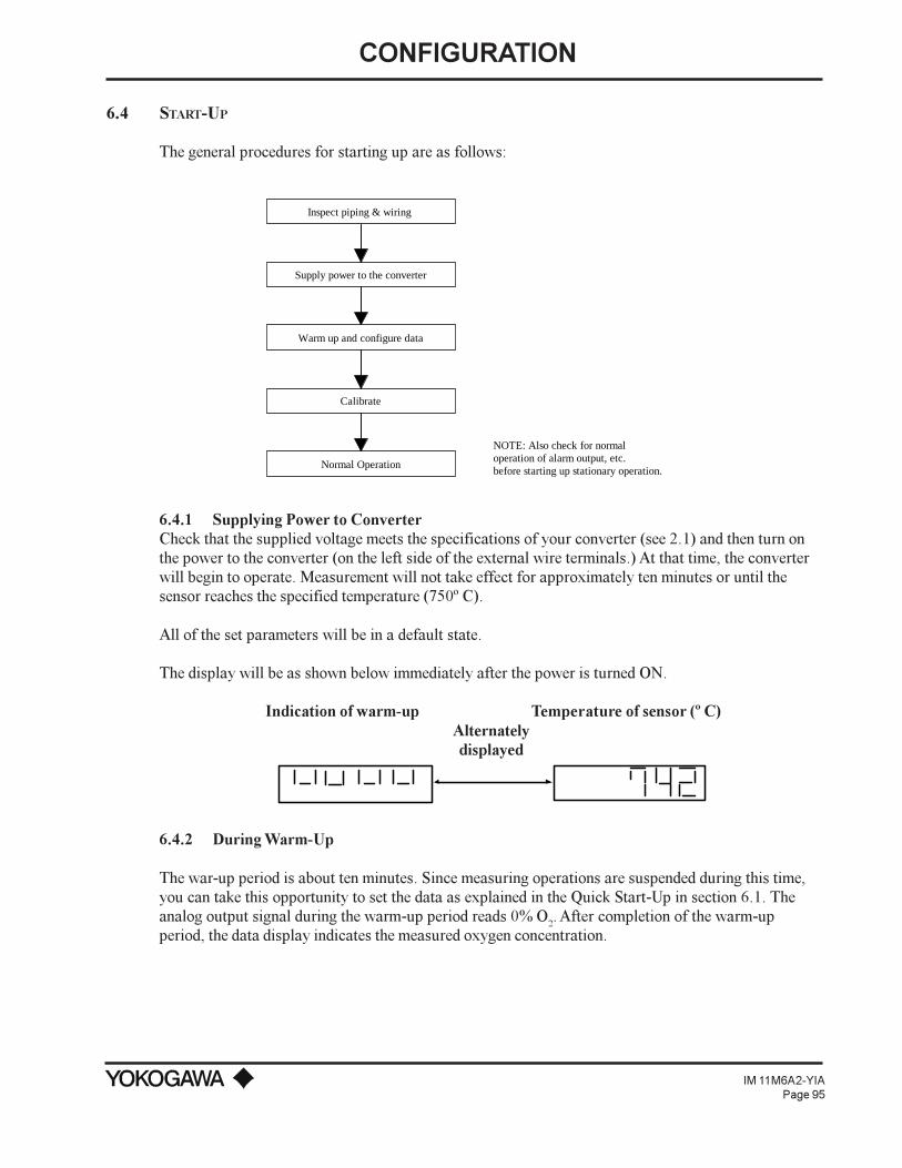
CONFIGURATION
IM 11M6A2-YIAPage 95
6.4 START-UP
The general procedures for starting up are as follows:
Supply power to the converter
Calibrate
Normal Operation
NOTE: Also check for normal operation of alarm output, etc. before starting up stationary operation.
Warm up and configure data
Inspect piping & wiring
6.4.1 Supplying Power to ConverterCheck that the supplied voltage meets the specifications of your converter (see 2.1) and then turn onthe power to the converter (on the left side of the external wire terminals.) At that time, the converterwill begin to operate. Measurement will not take effect for approximately ten minutes or until thesensor reaches the specified temperature (750º C).
All of the set parameters will be in a default state.
The display will be as shown below immediately after the power is turned ON.
Indication of warm-up Temperature of sensor (º C)Alternatelydisplayed
6.4.2 During Warm-Up
The war-up period is about ten minutes. Since measuring operations are suspended during this time,you can take this opportunity to set the data as explained in the Quick Start-Up in section 6.1. Theanalog output signal during the warm-up period reads 0% O2. After completion of the warm-upperiod, the data display indicates the measured oxygen concentration.

CONFIGURATION
IM 11M6A2-YIAPage 96
6.4.3 Data Setting ConfigurationThe ZA8C In-Situ Type Zirconia Oxygen Analyzer allows custom configuration functions for yourindividual application.
Basic data, e.g., parameters required for operation, are stored in EEPROM in the converter.Temporary data, as set forth individually, are stored in the RAM. The temporary data, read in theRAM, are preserved through the backup of an electric double-layer capacitor for a short time even ifthe main power supply fails. After that, however, the data in the RAM is lost while the stored data inthe converter changes to a default state.
Upon shipment, the data loaded into the converter are in the default state. When operation begins, setthe data to match each operation. The following table shows the default values.
Menu groups A & B are display functions which are discussed later in this chapter. The followingmenus are set up parameters required for accurate operation of your oxygen analyzer system.
GROUP C (0 THROUGH 7)
C-0 SPAN GAS CONCENTRATION
Set the oxygen concentration for the span gas used in calibration. If, for example, instrument air isused as a span gas, set the value at 20.6 vol% O
2 by entering 020.6.
Message display (Example)
C0 CAL GAS CONC (%O2)SPAN = 020.60
C-1 ZERO GAS CONCENTRATION
Set the oxygen concentration for the zero gas used for calibration. Set it for the certified gas value inthe cylinder you are using at present. If, for example, the concentration is 1 vol% O
2 enter 001.00.
Message display (Example)
C1 CAL GAS CONC (%O2) ZERO = 001.00
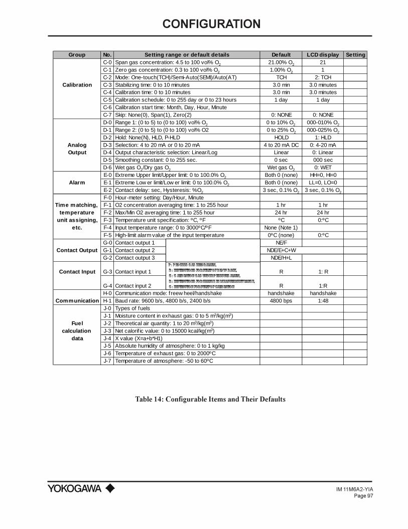
CONFIGURATION
IM 11M6A2-YIAPage 97
Group No. Setting range or default details Default LCD display SettingC-0 Span gas concentration: 4.5 to 100 vol% O2 21.00% O2 21C-1 Zero gas concentration: 0.3 to 100 vol% O2 1.00% O2 1C-2 Mode: One-touch(TCH)/Semi-Auto(SEMI)/Auto(AT) TCH 2: TCH
Calibration C-3 Stabilizing time: 0 to 10 minutes 3.0 min 3.0 minutesC-4 Calibration time: 0 to 10 minutes 3.0 min 3.0 minutesC-5 Calibration schedule: 0 to 255 day or 0 to 23 hours 1 day 1 dayC-6 Calibration start time: Month, Day, Hour, MinuteC-7 Skip: None(0), Span(1), Zero(2) 0: NONE 0: NONED-0 Range 1: (0 to 5) to (0 to 100) vol% O2 0 to 10% O2 000-010% O2
D-1 Range 2: (0 to 5) to (0 to 100) vol% O2 0 to 25% O2 000-025% O2
D-2 Hold: None(N), HLD, P-HLD HOLD 1: HLDAnalog D-3 Selection: 4 to 20 mA or 0 to 20 mA 4 to 20 mA DC 0: 4-20 mAOutput D-4 Output characteristic selection: Linear/Log Linear 0: Linear
D-5 Smoothing constant: 0 to 255 sec. 0 sec 000 secD-6 Wet gas O2/Dry gas O2 Wet gas O2 0: WETE-0 Extreme Upper limit/Upper limit: 0 to 100.0% O2 Both 0 (none) HH=0, HI=0
Alarm E-1 Extreme Low er limit/Low er limit: 0 to 100.0% O2 Both 0 (none) LL=0, LO=0E-2 Contact delay: sec, Hysteresis: %O2 3 sec, 0.1% O2 3 sec, 0.1% O2
F-0 Hour-meter setting: Day/Hour, MinuteTime matching, F-1 O2 concentration averaging time: 1 to 255 hour 1 hr 1 hr
temperature F-2 Max/Min O2 averaging time: 1 to 255 hour 24 hr 24 hrunit assigning, F-3 Temperature unit specif ication: ºC, ºF ºC 0:ºC
etc. F-4 Input temperature range: 0 to 3000ºC/ºF None (Note 1)F-5 High-limit alarm value of the input temperature 0ºC (none) 0:ºCG-0 Contact output 1 NE/F
Contact Output G-1 Contact output 2 NDE/E+C+WG-2 Contact output 3 NDE/H+L
Contact Input G-3 Contact input 1 R 1: R
G-4 Contact input 2 R 1:RH-0 Communication mode: f reew heel/handshake handshake handshake
Communication H-1 Baud rate: 9600 b/s, 4800 b/s, 2400 b/s 4800 bps 1:48J-0 Types of fuelsJ-1 Moisture content in exhaust gas: 0 to 5 m3/kg(m3)
Fuel J-2 Theoretical air quantity: 1 to 20 m3/kg(m3)calculation J-3 Net calorif ic value: 0 to 15000 kcal/kg(m3)
data J-4 X value (X=a+b*H1)J-5 Absolute humidity of atmosphere: 0 to 1 kg/kgJ-6 Temperature of exhaust gas: 0 to 2000ºCJ-7 Temperature of atmosphere: -50 to 60ºC
P: Process gas error alarm, B : Instructions for start of blow- back, G : C alibration gas under pressure alarm, R : Instructions for change in measurement range, C : Instruction for start of calibration
Table 14: Configurable Items and Their Defaults

CONFIGURATION
IM 11M6A2-YIAPage 98
C-2 CALIBRATION MODE
Select mode from AUTO (AT), SEMI-AUTO (SEMI) and ONE-TOUCH (TCH). Set the cursor to thecorresponding number. The calibration mode presently set is expressed with the member displayedunder the function number.
Message display (Example)
C2 CALIBRATION MODE2 0: AT 1: SEMI 2: TCH
Number of mode presently set.
C-3 STABILIZING TIME
Set a waiting period from the completion of the calibration to the beginning of measurements again, inminutes. Set an interval for the time between stopping the flow of the calibration gas and completingthe replacement of the calibration gas with measurement gas. If, for example, it is 3 minutes 30seconds enter 03.5.
The operation mode, switched to the maintenance mode (MAINT) during calibration operations, willreturn to the measurement mode (MEAS) after the stabilizing time has passed.
Message display (Example)
C3 STABILIZING TIME 03.5 minutes
C-4 CALIBRATION TIME
Set a time after which the converter reads the oxygen concentration of a calibration gas (span gas orzero gas). In automatic or semiautomatic calibration mode, set a time (in minutes) from which theconverter turns on the appropriate solenoid valve causing the calibration gas to flow to the probe. Inone-touch calibration, set a permissible maximum interval (in minutes) for the time between when youenter a positive answer (by pressing the YES key) in reply to the message Span (or Zero) valveopen Y? shown in the message display, and when the calibration value is completely read. If, forexample, for five minutes enter 05.0.
Upon the completion of the calibration time interval, you will see the message, Span (or Zero) calgood.
Message display (Example)
C4 CALIBRATION TIME 05.0 minutes

CONFIGURATION
IM 11M6A2-YIAPage 99
C-5 CALIBRATION FREQUENCY
In automatic calibration, you can set the interval from the time of starting a calibration to the time ofstarting the next calibration. Set in days or hours, according to the calibration frequency of yourprocess conditions. It is normally recommended that intervals of one to three months (30 to 90 days)be used. If a calibration interval of 60 days is to be set, select 0 from the settable-item selectionmessages thereby displaying the day-setting message and set 60 days by entering 060. If you wantto set 12 hours select 1 from the settable-item selection messages and enter 12 hours with 12.
Message display (Example)
C5 CAL INTERVAL 0: day 1: hr
C5 CAL INTERVAL (1) 12 hr
C5 CAL INTERVAL (0) 060 day
When "0" is selected from
When "1" is selected from
C-6 CALIBRATION START TIME
Set the date and time at which the first automatic calibration is to start. If is it 4:30 p.m., July 15,1994 set the date by entering 94/07/15 16:30.
Message display (Example)
C6 CAL START TIME 94/07/15 16:30
NOTE: If you change any parameters in C-0 through C-5 and are operating in the auto-cal mode, you mustenter a cal start time in C-6 later than present time and date.
C-7 SKIP
Calibration is normally performed for both zero and span points. However, either of them may beskipped (but both zero and span points should be calibrated once). If you do not want to skip either,select 0. For skipping span or zero point, select 1 or 2, respectively.
These assignments are effective for semiautomatic and automatic calibrations. You cannot omit themin one-touch calibration.

CONFIGURATION
IM 11M6A2-YIAPage 100
Message display (Example)
C7 SKIP0 0: NONE 1: SPN 2: ZR
GROUP D
D-0 OUTPUT RANGE 1Set the range of oxygen concentration to correspond to the analog output signal (4-20 mA or 0 to 20mADC). You can set a free range from 0 to 5 vol% O2 to 0 to 100 vol% O2. Also, a partial range isselectable provided the minimum operating span is 5 vol% O
2 under the condition that the ratio of
maximum/minimum is 1.3:1 or greater.
NOTE: If the output mode is set to Logarithm in function No. D-4, the minimum value of the outputrange is always 0.1 regardless of this setting.
Message display (Example)
D0 OUTPUT RANGE 1 000 - 010 %O2
D-1 OUTPUT RANGE 2Output Range 2 can be output only when the converter has the functions of contact input or digitalcommunication by the range change command. Similar to output range 1, set the oxygenconcentration range correspondent to the analog output signal (4-20 mADC or 0 to 20 mADC). Anyrange from 0 to 5 vol% O2 up to 0 to 100 vol% O2 can be set.
In addition, if the range selection command is to be made with a contact input, select Change inmeasurement range in function No. G-3 or G-4. However, if the command is made via digitalcommunications, do not select Change in measurement range. If selected, a command via digitalcommunications cannot be received.
Message display (Example)
D1 OUTPUT RANGE 2 010 - 025 %02
D-2 OUTPUT SIGNAL HOLD
You can select what the 4-20 mA output will do when the analyzer is not in the "MEAS" mode. Youcan have the output track the O2 level, hold at last reading or go to a predetermined level. "Ø" willtrack, "1" will hold last value and "2" will prompt you for the value you want the reading to go to.

CONFIGURATION
IM 11M6A2-YIAPage 101
When 2 is selected, a message for setting a preset value is then displayed, enter the value from thekeypad. Preset values are in vol% O2 units. If you want 5% (corresponding to 12 mADC on a 0-10%range), select 005.
NOTE: The output signal in a state other than normal operation, such as in data setting mode or duringwarm up, shows the value either for holding the preceding value for preset holding (where 2 isset), even if 0 is set. If the preset value is not set in the preset hold mode, the preceding valueholds.
Message display (Example)
D2 OUTPUT HOLD (2 ) PRESET HOLD = 000%
When "2" is assigned
D2 OUTPUT HOLD2 0:N 1: HLD 2: P - HLD
NOTE: This option only affects the 4-20 mA signal. The Red LED on the analyzer will always displayactual O
2 levels (wet basis).
D-3 TYPES OF OUTPUT SIGNALS
Assign the analog output signals to match your DCS or recorder's specifications. Enter 0 or 1 for4-20 mADC or 0 to 20 mADC, respectively.
Message display (Example)
D3 CURRENT OUTPUT0 0" 4-20 mA 1: 0-20 mA
D-4 OUTPUT SIGNAL CHARACTERISTICS
The relationship between the 4-20 mADC or 0 to 20 mADC analog output signal and oxygenconcentration is normally linear. However, you can modify it to logarithmic.
For a linear or logarithmic relationship, assign 0 or 1, respectively.
NOTE: For the relationship between the output current and oxygen concentration when selecting log seethe description of function No. A-5.
Message display (Example)
D4 OUTPUT SCALE0 0:Linear 1:Log

CONFIGURATION
IM 11M6A2-YIAPage 102
D-5 OUTPUT SMOOTHING CONSTANT
If the oxygen concentration of the measured gas changes suddenly, and you use these measured valuesdirectly to control operations, problems (e.g., frequent turning ON/OFF of operations) might occur. Toavoid such situations, you can introduce a time constant in order to smooth out the signal variations.You can set a time constant of up to 255 seconds, enter a suitable value from the keypad. If it is 30seconds, enter 030.
Message display (Example)
D5 SIGNAL DAMPING 030 sec
D-6 MOISTURE BASE IN MEASUREMENT GAS
Combustion gases contain moisture created by burning hydrogen in the fuel. If this moisture isremoved, the oxygen concentration will be higher than before. You can select whether the oxygenconcentration is wet or dry value before use. For wet or dry conditions, assign 0 or 1,respectively.
Set the moisture content required for the calculation according to function No. J-1 throughJ-7.
Message display (Example)
D6 WET/DRY 02 SELECT0 0:WET 1:DRY
GROUP E
E-0 SETTING OF HIGH HIGH-LIMIT/HIGH-LIMIT ALARMS
Set the level(s) for contact output signals for the high high-limit (HH) and/or high-limit (HL) alarms.If, for instance, you want to have an alarm set at an oxygen high-limit of 7.5 vol% O2 but deactivatethe high high-limit alarm, enter 000.0 for the high high-limit alarm (HH=) and 007.5 for the high-limit alarm (HI=).
For an alarm contact output, refer to function No. G-0 through G-2.
NOTE: The Analog Bargraph (Function A-0) will display the limit alarms under the bargraph.
Message display (Example)
E0 ALARM SET PT (%O2) HH = 000.0 HI = 007.5

CONFIGURATION
IM 11M6A2-YIAPage 103
E-1 SETTING OF LOW LOW-LIMIT/LOW-LIMIT ALARMS
Set the level(s) of contact output signals for the low low-limit (LL) and/or low-limit (LO) alarms. Ifyou want to have an alarm set at an oxygen extreme low limit of 2.5% and activate a low-limit alarmof 4.9%, enter 002.5 for the low low-limit alarm (LL=) and 004.9 for the low-limit alarm (LO=).
For an alarm contact output, refer to function No. G-0 through G-2.
NOTE: The Analog Bargraph (Function A-0) will display the limit alarms under the bargraph.
Message display (Example)
E1 ALARM SET PT (%O2) LL = 002.5 LO = 004.9
E-2 CONTACT OPERATION OF ALARM OUTPUT
When measured values return to a stationary range after leaving the alarm range, it is sometimesdesirable for existing alarm output to be reset conditionally instead of being reset immediately. Youcan set such conditions, i.e., operation delay and hysteresis. The operation delay, once set here, iseffective even after measured values shift from the stationary range to the alarm range. Set theoperation delay (in seconds) and the hysteresis in the oxygen concentration (vol% O
2), respectively.
To set an operation delay of five seconds and a hysteresis in the oxygen concentration of 2.0 vol% O2,enter 005 and 2.0 on the keypad.
NOTE: The operation delay set here is applied to all contact signals selected with function numbers G-0 toG-2.
Message display (Example)
E2 RL DELAY = 005SEC RL HYS =2.0 %O2
GROUP F
F-0 SETTING OF DATE AND TIME
Set the clock to the present date and time. If the present date/time isApril 26, 1994/6:45 p.m., enter 94/04/26 18:45 and press the ENTER key to activate the date andtime.
Message display (Example)
F0 CLOCK ENTRY 94/04/26 18:45

CONFIGURATION
IM 11M6A2-YIAPage 104
F-1 MEAN O2 CONCENTRATION CALCULATION TIME
Set the time for collecting data in order to calculate the mean oxygen concentration (indicated whenyou access function No. A-2). Measured data are collected and summarized in 60 second intervals,while averages are calculated every time a datum is collected. After the set time expires, the calculatedmean value is reset and the operation of calculating a new mean value begins all over again. If youwant to update accumulated data every 24 hours, set this function at 024. Accumulation of databegins from the time you press the entry key.
NOTE: The calculation of the mean value is activated every time a datum is collected. So, the longer thecalculation time is extended, the more data which are used in averaging are collected. If you use amean data periodically, you should take notice of this.
Message display (Example)
F1 AVERAGE INTERVAL 024 hr
F-2 TIME INTERVAL FOR MONITORING MAXIMUM/MINIMUM O2
The converter stores the maximum and minimum values of measured oxygen concentrations within aset time period. These values are displayed by accessing function No. A-1.
You can set the time period for storing these maximum and minimum values. If you want to store themfor a week, enter 168 (hr). The storage of data begins when you press the entry key. Storedmaximum and minimum values are updated by comparing them with the new data periodically. Whenthe set time expires, the stored values are reset and new maximum and minimum value storage beginsall over again.
Message display (Example)
F2 MAX, MIN INTERVAL 168 hr
F-3 SELECTING INPUT TEMPERATURE SCALE (º F/º C)Set the temperature scale to be º F or º C. If º F is selected you must enter a value of 32º F in functionF5, otherwise, the alarm lamp will remain in effect.
Message display (Example)
F3 TEMPERATURE UNIT1 0: ºC 1: ºF
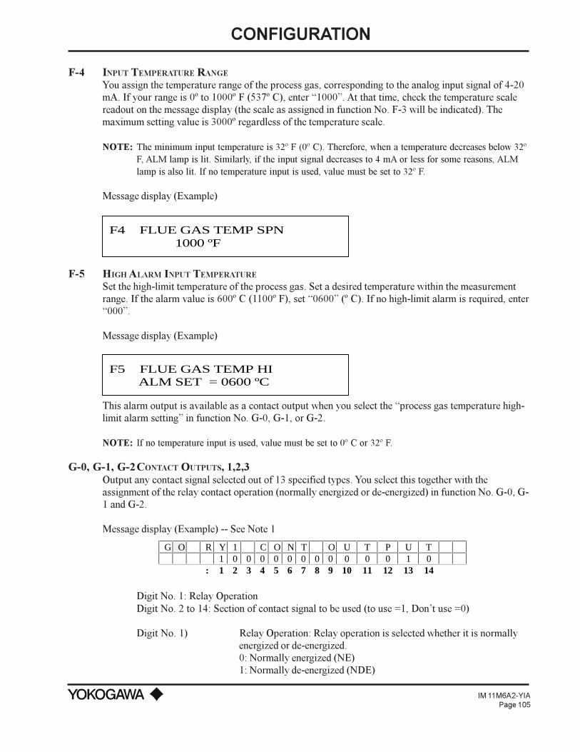
CONFIGURATION
IM 11M6A2-YIAPage 105
F-4 INPUT TEMPERATURE RANGE
You assign the temperature range of the process gas, corresponding to the analog input signal of 4-20mA. If your range is 0º to 1000º F (537º C), enter 1000. At that time, check the temperature scalereadout on the message display (the scale as assigned in function No. F-3 will be indicated). Themaximum setting value is 3000º regardless of the temperature scale.
NOTE: The minimum input temperature is 32º F (0º C). Therefore, when a temperature decreases below 32ºF, ALM lamp is lit. Similarly, if the input signal decreases to 4 mA or less for some reasons, ALMlamp is also lit. If no temperature input is used, value must be set to 32º F.
Message display (Example)
F4 FLUE GAS TEMP SPN 1000 ºF
F-5 HIGH ALARM INPUT TEMPERATURE
Set the high-limit temperature of the process gas. Set a desired temperature within the measurementrange. If the alarm value is 600º C (1100º F), set 0600 (º C). If no high-limit alarm is required, enter000.
Message display (Example)
F5 FLUE GAS TEMP HI ALM SET = 0600 ºC
This alarm output is available as a contact output when you select the process gas temperature high-limit alarm setting in function No. G-0, G-1, or G-2.
NOTE: If no temperature input is used, value must be set to 0º C or 32º F.
G-0, G-1, G-2CONTACT OUTPUTS, 1,2,3Output any contact signal selected out of 13 specified types. You select this together with theassignment of the relay contact operation (normally energized or de-energized) in function No. G-0, G-1 and G-2.
Message display (Example) -- See Note 1
G O R Y 1 C O N T O U T P U T1 0 0 0 0 0 0 0 0 0 0 0 1 0
: 1 2 3 4 5 6 7 8 9 10 11 12 13 14
Digit No. 1: Relay OperationDigit No. 2 to 14: Section of contact signal to be used (to use =1, Dont use =0)
Digit No. 1) Relay Operation: Relay operation is selected whether it is normallyenergized or de-energized.0: Normally energized (NE)1: Normally de-energized (NDE)

CONFIGURATION
IM 11M6A2-YIAPage 106
Digit No. 2) Error Occurrence: Relays operate when an error (code E1through E8) occurs.
Digit No. 3) High-high alarm (HH): Relay operates when the high-high limit set-point set with function No. E-0 is reached. (Note 2)
Digit No. 4) High Alarm (H): Relay operates when the high limit set-point set withfunction No. E-0 is reached . (Note 2)
Digit No. 5) Low Alarm (L): Relay operates when the low limit set-point set withfunction No. E-1 is reached. (Note 2)
Digit No. 6) Low-low Alarm (LL): Relay operates when the low-low limit set-point set with function No. E-1 is reached. (Note 2)
Digit No. 7) Entry (E): Relay operates when the maintenance mode is set.Digit No. 8) In Calibration (C): Relay operates when calibration action is selected.Digit No. 9) Range selection Answerback (R): Relay operates when the selection
command is input in a state where the range selection command (R)is set in function No. G-3 or No. 14.
Digit No. 10) In Warm-up (W): Relay operates when the detector is warmed up.Digit No. 11) LO - Calibration Gas pressure (G): Relay operates when the optional
pressure switch input is set in function G-3 or G-4 and switch closes.Digit No. 12) Process Gas Temperature High Alarm (T): Relay operates when
process gas rises above the input temperature high limit alarm set-point set with function No. F-5.
Digit No. 13) Solenoid Valve Assembly Drive (P): Relay operates when the processgas failure alarm is input in the state where the process gas failurealarm input (P) is set with function No. G-3 (Note 3) and the inputcloses.
Digit No. 14) Blowback (B): Relay operates when blowback state command inputis set with function G-3.
NOTE 1: When a function is to be used, it is specified by setting the corresponding digit to 1.
The default status is those shown below:G-0: (0) 1 0 0 0 0 0 0 0 0 0 0 0 0G-1: (1) 0 0 0 0 0 1 1 0 1 0 0 0 0G-2: (1) 0 0 1 1 0 0 0 0 0 0 0 0 0
NOTE 2: The relay is energized corresponding to the operation delay and hysteresis valve set in functionNo. E-2.
NOTE 3: Solenoid valve assembly drive is a function for driving a solenoid valve which supplies purgegas to the detector when gases not yet burned are mixed into the measuring gas. This functioncan also be applied to the cases where a sensor breakage accident due to condensed water shouldbe prevented by purging the calibration gas tubing at the restart of operation.
NOTE 4: On shipment, relay contacts for contact output relays are set as shown below.Function No. G-0 (Contact output #1) relay contacts: Break contact (closed when de-energized)Function No. G-1 (Contact output #2) relay contacts: Make contactFunction No. G-2 (Contact output #3) relay contacts: Make contact"

CONFIGURATION
IM 11M6A2-YIAPage 107
The contact type can be changed be resetting the jumper connector positions on the PCB. If Breakcontact (open when energized) is necessary, change it referring to subsection 6.1.6.
G-3 CONTACT INPUT 1The instrument can accept a total of two contact inputs assigned in functions No. G-3 and G-4. Youselect them from the following five types in function G-3:
0: Calibration gas under pressure alarm (G)1: Instructions for change in measurement range (R)2: Instructions for start of calibration (C)3: Process gas error alarm (P) (G-3 only)4: Instructions for start of blow-back (B) (G-3 only)
NOTE: The Blowback start command is valid when blowback is specified for function No. G-0 (or G-1 orG-2). The blowback start command contact input must be made for more than one second. When theconverter receives the blowback start command, it outputs a contact signal which turns ON and OFFabout every ten seconds for an interval the same as the calibration time set for function No. C-4,starting at 1 to 11 seconds after receiving the command.1) Blowback can be stopped with the HELP key.2) Blowback is not started during calibration because the calibration-start commands (AUTO,
SEMI-AUTO, ONE TOUCH) and calibrating action have priority.3) The blowback signal time does not include the stabilizing time set for function No. C-3.4) The analog output at the blowback operation becomes the mode specified for function No. D-2
(Non-Hold, Hold, or Preset Hold).
Blowback startcommand(contact input)
ON
OFF
ON
OFF
ON
OFF
About ten secondsBy pressing the HELP key,the operation can be stoppedin mid-stream.
1 to 11 seconds (start timing)
Time interval set to function No. C-4
One second or more
Blowback signal(contact output)
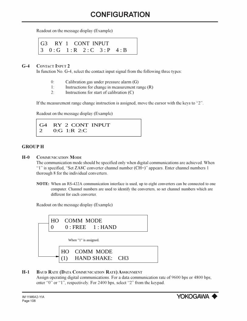
CONFIGURATION
IM 11M6A2-YIAPage 108
Readout on the message display (Example)
G3 RY 1 CONT INPUT3 0 : G 1 : R 2 : C 3 : P 4 : B
G-4 CONTACT INPUT 2In function No. G-4, select the contact input signal from the following three types:
0: Calibration gas under pressure alarm (G)1: Instructions for change in measurement range (R)2: Instructions for start of calibration (C)
If the measurement range change instruction is assigned, move the cursor with the keys to 2.
Readout on the message display (Example)
G4 RY 2 CONT INPUT2 0:G 1:R 2:C
GROUP H
H-0 COMMUNICATION MODE
The communication mode should be specified only when digital communications are achieved. When1 is specified, Set ZA8C converter channel number (CH=) appears. Enter channel numbers 1thorough 8 for the individual converters.
NOTE: When an RS-422A communication interface is used, up to eight converters can be connected to onecomputer. Channel numbers are used to identify the converters, so set channel numbers which aredifferent for each converter.
Readout on the message display (Example)
HO COMM MODE0 0 : FREE 1 : HAND
When "1" is assigned.
HO COMM MODE(1) HAND SHAKE: CH3
H-1 BAUD RATE (DATA COMMUNICATION RATE) ASSIGNMENT
Assign operating digital communications. For a data communication rate of 9600 bps or 4800 bps,enter 0 or 1, respectively. For 2400 bps, select 2 from the keypad.
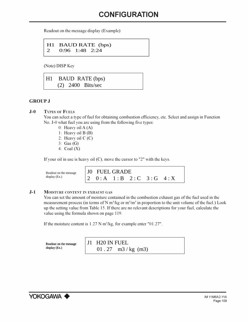
CONFIGURATION
IM 11M6A2-YIAPage 109
Readout on the message display (Example)
H1 BAUD RATE (bps)2 0:96 1:48 2:24
(Note) DISP Key
H1 BAUD RATE (bps) (2) 2400 Bits/sec
GROUP J
J-0 TYPES OF FUELS
You can select a type of fuel for obtaining combustion efficiency, etc. Select and assign in FunctionNo. J-0 what fuel you are using from the following five types:
0: Heavy oil A (A)1: Heavy oil B (B)2: Heavy oil C (C)3: Gas (G)4: Coal (X)
If your oil in use is heavy oil (C), move the cursor to "2" with the keys.
J0 FUEL GRADE2 0 : A 1 : B 2 : C 3 : G 4 : X
Readout on the messagedisplay (Ex.)
J-1 MOISTURE CONTENT IN EXHAUST GAS
You can set the amount of moisture contained in the combustion exhaust gas of the fuel used in themeasurement process (in terms of N m3/kg or m3/m3 in proportion to the unit volume of the fuel.) Lookup the setting value from Table 15. If there are no relevant descriptions for your fuel, calculate thevalue using the formula shown on page 119.
If the moisture content is 1.27 N m3/kg, for example enter "01.27".
J1 H20 IN FUEL 01 . 27 m3 / kg (m3)
Readout on the messagedisplay (Ex.)Readout on the messagedisplay (Ex.)

CONFIGURATION
IM 11M6A2-YIAPage 110
J-2 THEORETICAL AIR QUANTITY
You can set the theoretical air quantity required for the fuel used in the measurement process to ignite(N m3/kg or m3/m3). Look up the setting value from Table 15. If there are no relevant descriptions foryour fuel, calculate the value using the formula shown on page 119.
If the theoretical quantity is 10.7 N m3/kg, enter "10.70".
J2 THEORITICAL AIR 10 . 70 m3 / kg (m3)
Readout on the messagedisplay (Ex.)
J-3 NET CALORIFIC VALUE
You can set the net calorific value of the fuel used in the measurement process to ignite (kcal/kg orkcal/m3). Look up the setting value from Table 15. If there are no relevant descriptions for your fuel,calculate the value using the formula shown on page 119.
If the net calorific value is 9860 kcal/kg, enter "09860".
J3 NET CALORIFIC VAL 09860 kcal / kg (m3)
Readout on the messagedisplay (Ex.)
J-4 X VALUE (X = A + B * H1)
The X value (N m3/kg or m3/m3) is the coefficient provided with each fuel. Look up the x value of thefuel used from Table 15. If there are no relevant descriptions for your fuel, calculate the value usingthe formula shown on page 119.
If the x value is 0.773 (m3/kg), for instance, round off the value to the second decimal place and enter"00.77".
J4 VALUE OF X 00 . 77 m3 / kg (m3)
Readout on the messagedisplay (Ex.)
J-5 ABSOLUTE HUMIDITY OF ATMOSPHERE
You can set the absolute humidity of the atmosphere used in igniting (moisture: kg/dry air :kg). If theabsolute humidity is 0.021 kg/kg, enter "0.021".
For your reference, a graph for determining absolute humidity by the temperature indications of apsychrometer is shown in Figure 57. It is a little inferior in accuracy. If the exact humidity is required,determine the value by referring to References such as JIS B8222, "Heat Balancing of Boilers forLand Use."

CONFIGURATION
IM 11M6A2-YIAPage 111
J5 ABS HMD OF AIR 0 . 0210 kg / kg
Readout on the messagedisplay (Ex.)
J-6 TEMPERATURE OF EXHAUST GAS
You can set the temperature of the exhaust gas in the actual combustion process (º C).
If the temperature of the exhaust gas is 450º C, enter "0450".
J6 FUEL GAS TEMP 0450 º C
Readout on the messagedisplay (Ex.)
J-7 TEMPERATURE OF ATMOSPHERE
You can set the temperature of the atmosphere taken in for igniting (º C). Measure the temperature ofthe atmosphere at a place as close to the air intake port as possible.
If the temperature is minus 1º C, for instance, enter "-001". You can alternately display plus andminus signs by pressing the increase key.
J7 AMB AIR TEMP - 001 º C
Readout on the messagedisplay (Ex.)
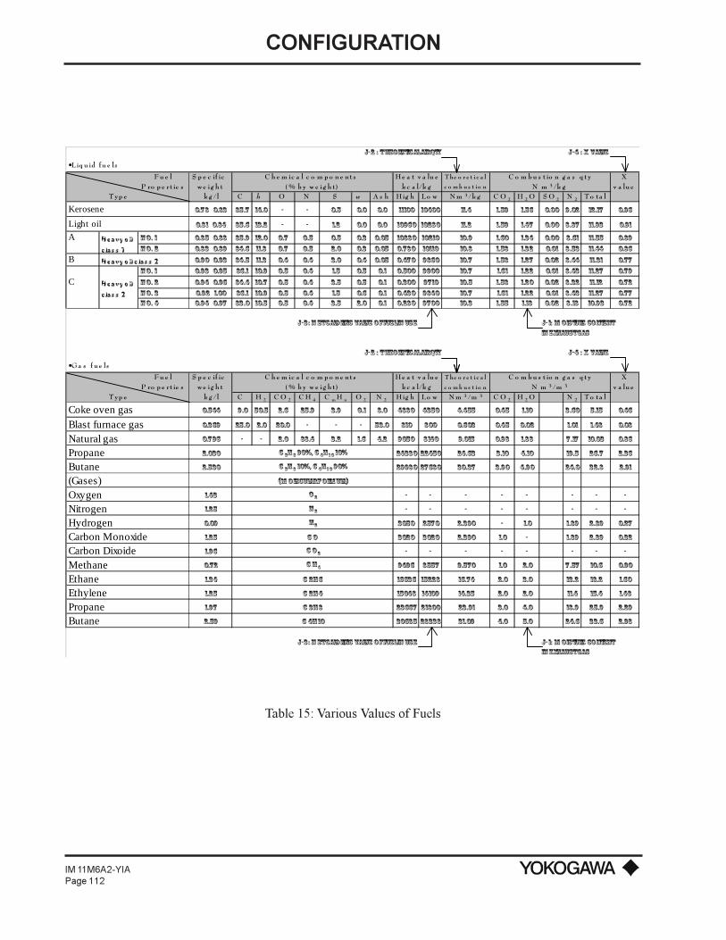
CONFIGURATION
IM 11M6A2-YIAPage 112
J-2 : Theoretical air qty J-4 : X value
•Liq u id fu e ls
F u e l S p e c if ic C h e m ic a l c o m p o n e n t s H e a t v a lu e T he o r e t i c a l C o m b u s t io n g a s q t y XP ro p e rt ie s w e ig h t ( % b y w e ig h t ) k c a l/k g c o m b u s t io n N m 3 /k g v a lu e
T yp e k g / l C h O N S w A s h H ig h Lo w N m 3 /k g C O 2 H 2 O S O 2 N 2 T o ta l
Kerosene 0.78~ 0.83 85.7 14.0 - - 0.5 0.0 0.0 11100 10400 11.4 1.59 1.56 0.00 9.02 12.17 0.96
Light oil 0.81~ 0.84 85.6 13.2 - - 1.2 0.0 0.0 10960 10280 11.2 1.59 1.47 0.00 8.87 11.93 0.91
A Heavy o il N o. 1 0.85~ 0.88 85.9 12.0 0.7 0.5 0.5 0.3 0.05 10880 10210 10.9 1.60 1.34 0.00 8.61 11.55 0.89
c las s 1 N o. 2 0.83~ 0.89 84.6 11.8 0.7 0.5 2.0 0.3 0.05 0.780 10110 10.8 1.58 1.32 0.01 8.53 11.44 0.86
B Heavy o il c las s 2 0.90~ 0.93 84.5 11.3 0.4 0.4 3.0 0.4 0.05 0.470 9860 10.7 1.58 1.27 0.02 8.44 11.31 0.77
N o. 1 0.93~ 0.95 86.1 10.9 0.5 0.4 1.5 0.5 0.1 0.500 9900 10.7 1.61 1.22 0.01 8.43 11.27 0.79
C Heavy o il N o. 2 0.94~ 0.96 84.4 10.7 0.5 0.4 3.5 0.5 0.1 0.300 9710 10.5 1.58 1.20 0.02 8.32 11.12 0.72
c las s 2 N o. 3 0.92~ 1.00 86.1 10.9 0.5 0.4 1.5 0.6 0.1 0.430 9840 10.7 1.61 1.22 0.01 8.43 11.27 0.77N o. 4 0.94~ 0.97 83.0 10.5 0.5 0.4 3.5 2.0 0.1 0.280 9700 10.3 1.55 1.18 0.02 8.18 10.93 0.72
J-3: N et calorific value of fuel in use J-1: M oisture content in exhaust gas
J-2 : Theoretical air qty J-4 : X value
•G a s f u e ls
F u e l S p e c if ic C h e m ic a l c o m p o n e n t s H e a t v a lu e T he o r e t i c a l C o m b u s t io n g a s q t y XP ro p e rt ie s w e ig h t ( % b y w e ig h t ) k c a l/k g c o m b u s t io n N m 3 /m 3 v a lu e
T yp e k g / l C H 2 C O 2 C H 4 C m H n O 2 N 2 H ig h Lo w N m 3 /m 3 C O 2 H 2 O N 2 T o ta l
Coke oven gas 0.544 9.0 50.5 2.6 25.9 3.9 0.1 8.0 4880 4350 4.455 0.45 1.10 3.60 5.15 0.46
Blast furnace gas 0.369 25.0 2.0 20.0 - - - 53.0 810 800 0.603 0.45 0.02 1.01 1.48 0.08
Natural gas 0.796 - - 2.0 88.4 3.2 1.6 4.2 9050 8140 9.015 0.98 1.88 7.17 10.03 0.86
Propane 2.030 C 3H 8 90%, C 4H1 0 10% 24380 22450 24.63 3.10 4.10 19.5 26.7 2.36
Butane 2.530 C 3H 8 10%, C 4H1 0 90% 29980 27680 30.37 3.90 4.90 24.0 32.8 2.91
(Gases) (M olecular Formula)
Oxygen 1.43 O 2 - - - - - - - -
Nitrogen 1.25 N 2 - - - - - - - -
Hydrogen 0.09 H2 3050 2570 2.390 - 1.0 1.89 2.89 0.27
Carbon Monoxide 1.25 C O 3020 3020 2.390 1.0 - 1.89 2.89 0.32
Carbon Dixoide 1.96 C O 2 - - - - - - - -
Methane 0.72 C H4 9496 8557 9.570 1.0 2.0 7.57 10.6 0.90
Ethane 1.34 C 2H6 16636 15228 16.74 2.0 3.0 13.2 18.2 1.60
Ethylene 1.25 C 2H4 15048 14109 14.35 2.0 2.0 11.4 15.4 1.48
Propane 1.97 C 3H8 23667 21800 23.91 3.0 4.0 18.9 25.9 2.29
Butane 2.59 C 4H10 30685 28338 31.09 4.0 5.0 24.6 33.6 2.98
J-3: N et calorific value of fuel in use J-1: M oisture content in exhaust gas
Table 15: Various Values of Fuels
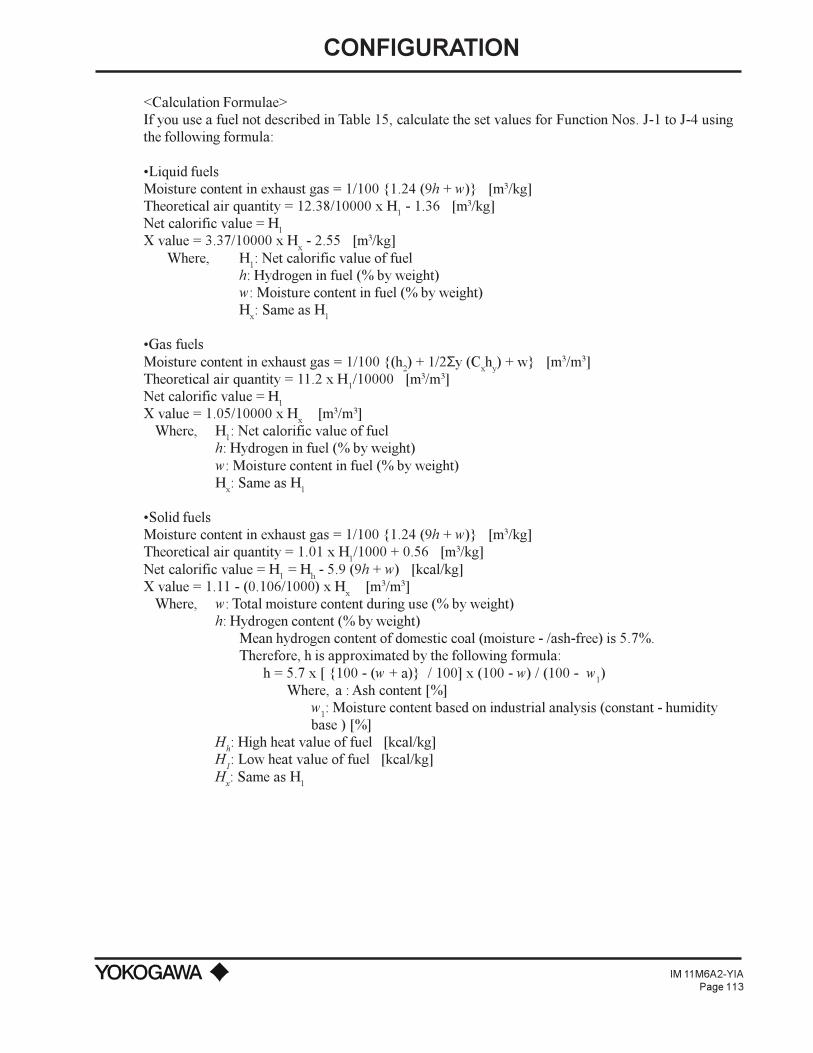
CONFIGURATION
IM 11M6A2-YIAPage 113
<Calculation Formulae>If you use a fuel not described in Table 15, calculate the set values for Function Nos. J-1 to J-4 usingthe following formula:
Liquid fuelsMoisture content in exhaust gas = 1/100 1.24 (9h + w) [m3/kg]Theoretical air quantity = 12.38/10000 x H1 - 1.36 [m3/kg]Net calorific value = H1
X value = 3.37/10000 x Hx - 2.55 [m3/kg]
Where, H1: Net calorific value of fuelh: Hydrogen in fuel (% by weight)w: Moisture content in fuel (% by weight)Hx: Same as H1
Gas fuelsMoisture content in exhaust gas = 1/100 (h2) + 1/2Σy (Cxhy) + w [m3/m3]Theoretical air quantity = 11.2 x H1/10000 [m3/m3]Net calorific value = H1
X value = 1.05/10000 x Hx [m3/m3]
Where, H1: Net calorific value of fuelh: Hydrogen in fuel (% by weight)w: Moisture content in fuel (% by weight)Hx: Same as H1
Solid fuelsMoisture content in exhaust gas = 1/100 1.24 (9h + w) [m3/kg]Theoretical air quantity = 1.01 x H
1/1000 + 0.56 [m3/kg]
Net calorific value = H1 = Hh - 5.9 (9h + w) [kcal/kg]X value = 1.11 - (0.106/1000) x Hx [m
3/m3]Where, w: Total moisture content during use (% by weight)
h: Hydrogen content (% by weight)Mean hydrogen content of domestic coal (moisture - /ash-free) is 5.7%.Therefore, h is approximated by the following formula:
h = 5.7 x [ 100 - (w + a) / 100] x (100 - w) / (100 - w1)Where, a : Ash content [%]
w1: Moisture content based on industrial analysis (constant - humiditybase ) [%]
Hh: High heat value of fuel [kcal/kg]H
1: Low heat value of fuel [kcal/kg]
Hx: Same as H1

CONFIGURATION
IM 11M6A2-YIAPage 114
Figure 57: Absolute Humidity of Air

CONFIGURATION
IM 11M6A2-YIAPage 115
6.4.4 CalibrationThe calibration of this instrument is carried out by comparing either the oxygen concentration of thezero gas or of the span gas with the measured value of the relevant calibration gas. The referenceoxygen concentration (set in C-0 and C-1) is already read into the memory of the converter. Theconverter detects the deviation of the measured result from this value and automatically corrects it.
The following three methods of calibration are available; further calibrations can be carried outperiodically or occasionally, and the calibration gas for these later calibrations can be automatically ormanually introduced. You can select any of these methods by registering it in the converter.
1) Automatic CalibrationA calibration operation begins when you set the calibration start time and the calibration fre-quency, and then press the key (or enter an external contact signal) to begin. All operations relatedto calibration (e.g., calibration time, opening/closing of the solenoid valve and sequence) areautomatically activated based on the data set in the converter.
NOTE: If you manually start a calibration from the keypad, digital input or serial communication, theautomatic sequence is aborted. A new start time must be entered in C-6.
2) Semiautomatic calibrationIn this mode, calibration begins only when the converter is operated with the keys or receivesstarting instructions from a contact signal through an external circuit. The other details are thesame as those for “automatic calibration”.
3) One-touch calibrationIn this mode, operate keys to send the calibration gas or for other procedures depending on thereadout on the message display on the converter after you have given the calibration start instruc-tions (in the same way as for semiautomatic calibration). Other calibration operations are auto-matically processed by the converter.
Preparation for calibration
(1)
(2)
(3)
(4)
Adjust opening in the valve for calibration gas(automatic or semi-automatic calibration)
Check the set calibration data
Check calibration operation
Execute calibration
Checking the set calibration dataSequentially display the data from Codes C-0 to C-7 on the message display of the converter andcheck for errors in the set data (e.g., the selected calibration method and the concentration of thecalibration gas).

CONFIGURATION
IM 11M6A2-YIAPage 116
6.5 STATIONARY OPERATION
6.5.1 Collection of Control DataYou can display Maximum/Minimum O2 concentration of function No. A-1 or Mean O2
concentration of A-2 on the message display.
6.5.2 TroubleshootingIf an error occurs:1) A “FAIL” LED on the converter status display lights up;2) An error code appears in the data display area;3) Error messages appear in the message display area. If the error messages do not appear, push the
"DISP" key.
Every time an error occurs, immediately correct it according to the instructions in chapter 11. Thefollowing error codes are operable.
Error Code Error Detail Error StatusE--1 Sensor (cell) error Goes into fail mode, automatically turning OFF the pow er supply to
the detector heater.
E--2 Sensor temp "LOW" Goes into fail mode, automatically turning OFF the pow er supply to the detector heater.
E--3 Sensor temp "HIGH" Goes into fail mode, automatically turning OFF the pow er supply to the detector heater.
E--4 A/D (Analog circuit) error
Goes into fail mode, automatically turning OFF the pow er supply to the detector heater.
E--5 Calibration value "ZERO"
(Displayed during calibration) the present zero point calibration value is not affected.
E--6 Calibration value "SPAN"
(Displayed during calibration) the present zero point calibration value is not affected.
E--7 Start pow er stability time over
(Displayed during calibration) the present zero point calibration value is not affected.
E--8 ROM, RAM error Goes into fail mode, automatically turning OFF the pow er supply to the detector heater.
ooo (Display erased)
Digital circuit error pow er failure
Goes into fail mode, automatically turning OFF the pow er supply to the detector heater. (Displayed upon restart after remedying the pow er failure). Data values default.
Table 16: Error Codes, Details and Status
NOTE: E--5, E--6 or E--7 is displayed alternately with the O2 concentration.
6.5.3 Checking Operating ConditionsIn order to maintain normal operating conditions, determine which items are to be inspectedperiodically, and check them regularly for errors.
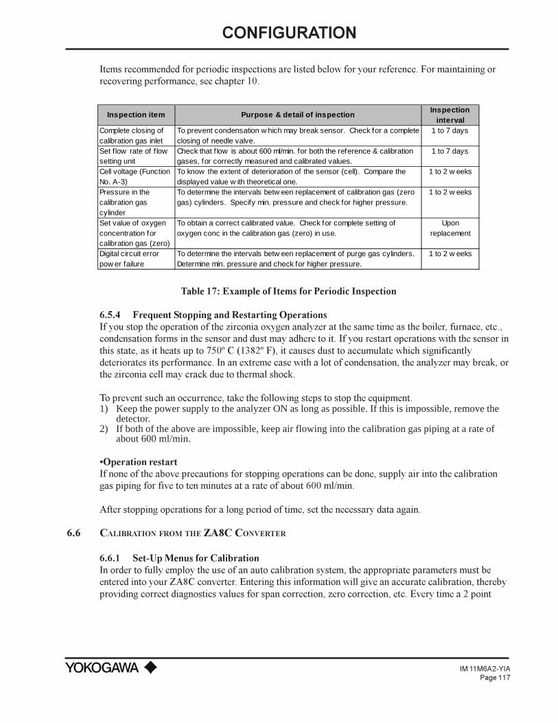
CONFIGURATION
IM 11M6A2-YIAPage 117
Items recommended for periodic inspections are listed below for your reference. For maintaining orrecovering performance, see chapter 10.
Inspection item Purpose & detail of inspectionInspection
intervalComplete closing of calibration gas inlet
To prevent condensation w hich may break sensor. Check for a complete closing of needle valve.
1 to 7 days
Set flow rate of f low setting unit
Check that f low is about 600 ml/min. for both the reference & calibration gases, for correctly measured and calibrated values.
1 to 7 days
Cell voltage (Function No. A-3)
To know the extent of deterioration of the sensor (cell). Compare the displayed value w ith theoretical one.
1 to 2 w eeks
Pressure in the calibration gas cylinder
To determine the intervals betw een replacement of calibration gas (zero gas) cylinders. Specify min. pressure and check for higher pressure.
1 to 2 w eeks
Set value of oxygen concentration for calibration gas (zero)
To obtain a correct calibrated value. Check for complete setting of oxygen conc in the calibration gas (zero) in use.
Upon replacement
Digital circuit error pow er failure
To determine the intervals betw een replacement of purge gas cylinders. Determine min. pressure and check for higher pressure.
1 to 2 w eeks
Table 17: Example of Items for Periodic Inspection
6.5.4 Frequent Stopping and Restarting OperationsIf you stop the operation of the zirconia oxygen analyzer at the same time as the boiler, furnace, etc.,condensation forms in the sensor and dust may adhere to it. If you restart operations with the sensor inthis state, as it heats up to 750º C (1382º F), it causes dust to accumulate which significantlydeteriorates its performance. In an extreme case with a lot of condensation, the analyzer may break, orthe zirconia cell may crack due to thermal shock.
To prevent such an occurrence, take the following steps to stop the equipment.1) Keep the power supply to the analyzer ON as long as possible. If this is impossible, remove the
detector.2) If both of the above are impossible, keep air flowing into the calibration gas piping at a rate of
about 600 ml/min.
Operation restartIf none of the above precautions for stopping operations can be done, supply air into the calibrationgas piping for five to ten minutes at a rate of about 600 ml/min.
After stopping operations for a long period of time, set the necessary data again.
6.6 CALIBRATION FROM THE ZA8C CONVERTER
6.6.1 Set-Up Menus for CalibrationIn order to fully employ the use of an auto calibration system, the appropriate parameters must beentered into your ZA8C converter. Entering this information will give an accurate calibration, therebyproviding correct diagnostics values for span correction, zero correction, etc. Every time a 2 point
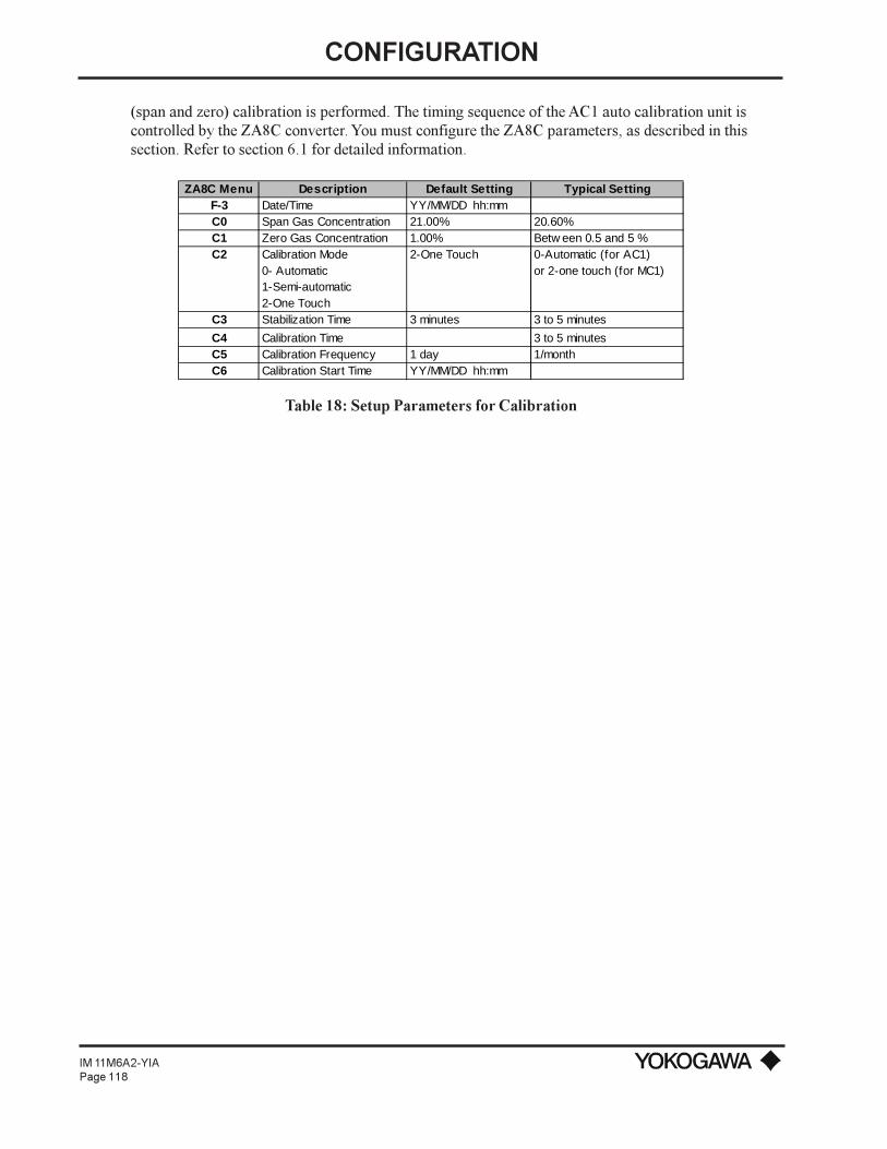
CONFIGURATION
IM 11M6A2-YIAPage 118
(span and zero) calibration is performed. The timing sequence of the AC1 auto calibration unit iscontrolled by the ZA8C converter. You must configure the ZA8C parameters, as described in thissection. Refer to section 6.1 for detailed information.
ZA8C Menu Description Default Setting Typical SettingF-3 Date/Time YY/MM/DD hh:mmC0 Span Gas Concentration 21.00% 20.60%C1 Zero Gas Concentration 1.00% Betw een 0.5 and 5 %C2 Calibration Mode 2-One Touch 0-Automatic (for AC1)
0- Automatic or 2-one touch (for MC1)1-Semi-automatic2-One Touch
C3 Stabilization Time 3 minutes 3 to 5 minutes
C4 Calibration Time 3 to 5 minutesC5 Calibration Frequency 1 day 1/monthC6 Calibration Start Time YY/MM/DD hh:mm
Table 18: Setup Parameters for Calibration

SERIAL COMMUNICATION
IM 11M6A2-YIAPage 119
VII. SERIAL COMMUNICATION
To allow for RS-232C or RS-422A communications, you must connect the converter to a PC.
7.1 WIRING WITH RS-232C COMMUNICATIONS CABLE
Figure x shows terminal connections of RS-232C communication cable. RS-232C communicationsare carried out by connecting only one converter to one computer.
Figure 58: Wiring of RS-232C Communications Cable
<Specifications for Communication Cable and Maximum Length>Use a three-conductor - (nominal cross section: 0.2 mm2) or two twisted pair (24 AWG or thicker) -shielded cable for RS-232C communications wiring. In addition, the cable length is limited up to15 m.
In end-treating the cable, attach crimping type solderless terminal lugs matching M4 (4 mm) screws tothe cable end to be connected to the converter terminals.
7.2 WIRING WITH RS-422A COMMUNICATIONS CABLE
RS-422A communication can be carried out by connecting up to eight converters to one computer. Inthe ZA8C converter, communication I/O signals are not isolated. If the computer is distant(communication cable length is 15 m or more as a guideline) from the converter and thus their groundpotentials cannot be equalized, use a computer having I/O signal isolating type interface.
Figure 51 shows terminal connections of RS-422A communication cable.
<Notices in Making Wiring>1) Communication cables away from power cables which may become noise sources. In addition,
cables so that adjacent cables are not in parallel with each other.2) If more than one converter is to be connected to a computer, ground wiring should be such that
the ground potentials of each converter are equal.

SERIAL COMMUNICATION
IM 11M6A2-YIAPage 120
Figure 59: Connections for RS-422A Communications
<Specifications for Communication Cable and Maximum Length>For RS-232C communication cable, use two twisted pair (24 AWG or thicker) shielded cables of Ø8to Ø11 mm O.D. so that the cable impedance is 100Ω and cable capacitance is 50 pF/m or less. It isrecommended that the cable length be within 15 m to balance ground potentials. However, if acomputer having I/O signal isolating interface is used, the cable length may be extended up to 500 m.In this case, the ground system wiring should be made in a procedure shown in figure 59.
As end treatment of the cable, attach the crimping type solderless terminal lugs matching M4 (4 mm)screws to the end of the cable to be connected to the converter terminals. Expose the conductors fromthe cable shield as short as possible.
Figure 60: Connections for RS-422A Communications (when using an I/O isolating computer)

SERIAL COMMUNICATION
IM 11M6A2-YIAPage 121
7.3 SPECIFICATIONS FOR ZA8C CONVERTER COMMUNICATIONS (RS-232C OR RS-422A)
Classifications Item DescriptionSignal Level Conforming to EIA RS-232C or RS-422A standards I/O signal not isolatedCommunication System Start-Stop system, Half Duplex
•RS-232C: Tw o-w ire system •RS-422A: Four-w ire system, multi-drop connection - number of computer converters = 1: N (N = 1 to 8)
Communication Distance •RS-232C: Up to 15m•RS-422A: Up to 500m (betw een I/O isolated computer and ZA8C converter)
Specifications Communication Rate 2,400, 4,800, 9,600 bps sw itchingTransmission Procedure No procedure, handshaking transfer. In the case of "no procedure" data
transmission only (transmission period: 10 seconds)Data Length 8 bitsParity NoneStart Bit 1Stop Bit 1Communication Code ASCII codeReception (1) Zero and span calibration request, Calibration abort request(2) Analog
output range selection signalContents Transmission Time, O2 concentration (w et and dry), cell emf, cell temperature, error
codes, alarm number, status number, calibration coefficient, cell resistance, response time, cell life, exhaust gas temperature, O2 average value, O2 averaging time, max. and min. O2
Table 19: Communication Specifications
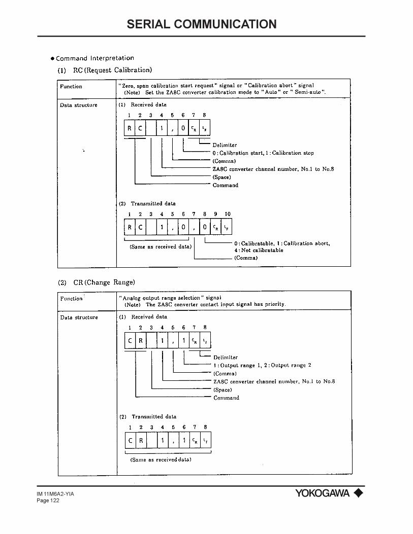
SERIAL COMMUNICATION
IM 11M6A2-YIAPage 122
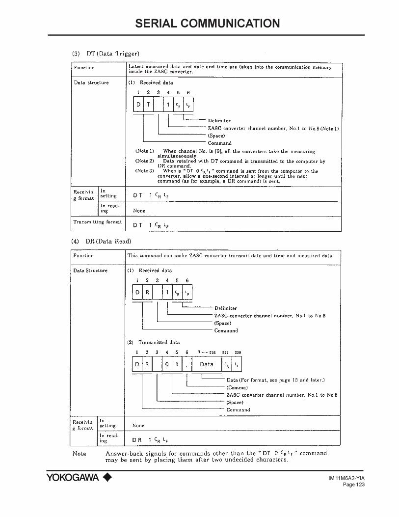
SERIAL COMMUNICATION
IM 11M6A2-YIAPage 123

SERIAL COMMUNICATION
IM 11M6A2-YIAPage 124

SERIAL COMMUNICATION
IM 11M6A2-YIAPage 125

SERIAL COMMUNICATION
IM 11M6A2-YIAPage 126
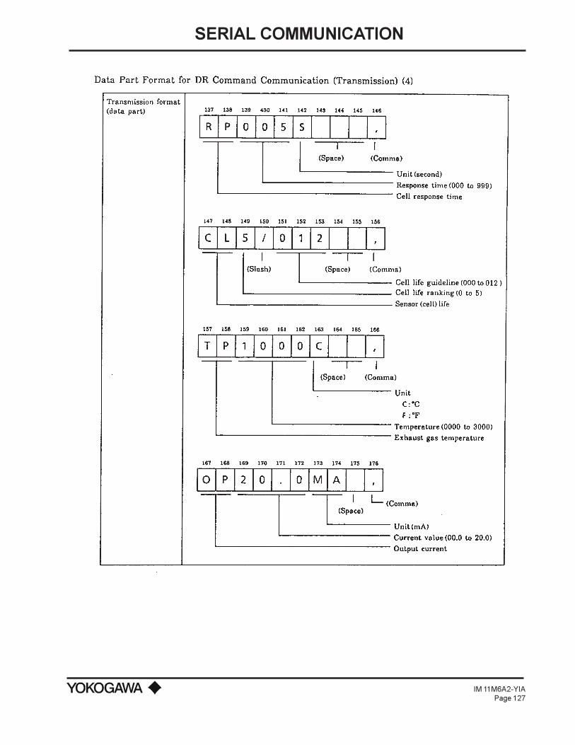
SERIAL COMMUNICATION
IM 11M6A2-YIAPage 127

SERIAL COMMUNICATION
IM 11M6A2-YIAPage 128

CALIBRATION
IM 11M6A2-YIAPage 129
VIII. CALIBRATION
8.1 CALIBRATION PROCEDURES
8.1.1 Principles of the Zirconia Oxygen AnalyzerBefore detailing calibration, the principles of measuring with a zirconia oxygen analyzer will bedescribed.
A solid electrolyte such as zirconia allows the conductivity of oxygen ions in a high temperature state.Therefore, when a zirconia-plated element with platinum electrodes on both sides is heated up incontact with gases having different partial-oxygen pressures on each side, the element shows theaction of the concentration cell. In other words, the electrode in contact with a gas with a higherpartial-oxygen pressure acts as a negative electrode. As the gas comes in contact with the zirconiaelement in this negative electrode, oxygen molecules in the gas acquire electrons and become ions.Moving in the zirconia element, they eventually arrive at the positive electrode on the opposite side.There, the electrons are released and the ions return to oxygen molecules. This reaction is indicated asfollows:
Negative electrode: O2 + 4e → 2 O2-
Positive electrode: 2 O2- → O2 + 4e
The electromotive force E (mV) between the two electrodes, generated by the reaction, is governed byNernst's equation as follows:
....................(1)
Where:R: Gas constant
T : Absolute temperaturen : 4F : the Faraday constantPX : Oxygen concentration in the gas in contact with the negative zirconia electrode (%)PA : Oxygen concentration in the gas in contact with the positive zirconia electrode (%)
Assuming the zirconia element is heated up to 750ºC, then the equation (1) becomes:
....................(2)
With this analyzer, the sensor (zirconia element) is heated up to 750ºC, so the relationship of equation(2) remains valid. At that time, a relationship, as in Figure x, is effected between the oxygenconcentration of the sample gas in contact with the positive electrode and the electromotive force ofthe sensor (= cell), where a comparison gas of reference air is used on the negative electrode side.

CALIBRATION
IM 11M6A2-YIAPage 130
Figure 61: Oxygen Concentration in Measurement Gas vs Cell Voltage (21.0% O2 Equivalent)
Measurement principles of a zirconia oxygen analyzer have been described above. However, therelationship between oxygen concentration and the electromotive force of a cell is only a theoreticalone. Usually, a practical sensor shows a slight deviation from the theoretical value. This is the reasonwhy calibration is required. It's performed to obtain a calibration curve for correcting a deviation froma theoretical cell electromotive force.
8.1.2 Calibration GasA gas with a known oxygen concentration is used for calibration. Normal calibration is performedusing 2 different gases: a zero gas of low oxygen concentration and a span gas of high oxygenconcentration. In some cases, only one or the other gas may be used for calibration. However, even ifonly one of the gases is normally used, calibration using both gases should be done at least once.
The zero gas normally used has an oxygen concentration of 0.95 to 1.0 vol% O2 with a balance ofnitrogen gas (N2). The span gas widely used is clean air (i.e., instrument air).

CALIBRATION
IM 11M6A2-YIAPage 131
8.1.3 CompensationThe deviation of a measured value from the theoretical cell electromotive force is checked by themethod in figures 61 or 62.
Figure 61 shows a 2-point calibration using 2 gases: zero and span. Cell electromotive forces for aspan gas with an oxygen concentration p1 and a zero gas with an oxygen concentration p2 aremeasured while determining a calibration curve passing between these 2 points. The oxygenconcentration of the measurement gas is determined from this calibration curve. In addition, thecalibration curve corrected by calibration is compared with the theoretical calibration curve fordetermining the zero point correction ration represented by B/A x 100(%) on the basis of A, B and Cshown in figure xa and the span point correction ration of C/A x 100(%). If the zero point correctionratio exceeds a range of 100 ±30% or the span point correction ratio becomes larger than ±0.18%,calibration of the sensor become impossible.
Figure 62: Calculation of a Calibration Curve and Correction Factorin a 2-point Calibration Using Zero and Span Gases
Figure 62 shows a 1-point calibration using only a span gas. In this case, only the cell electromotiveforce for a span gas with an oxygen concentration p1 is measured. The cell electromotive force for thezero gas is carried over from a previous measurement to obtain the calibration curve. The principles ofcalibration using only a span gas also applies to the 1-point calibration method using a zero gas only.
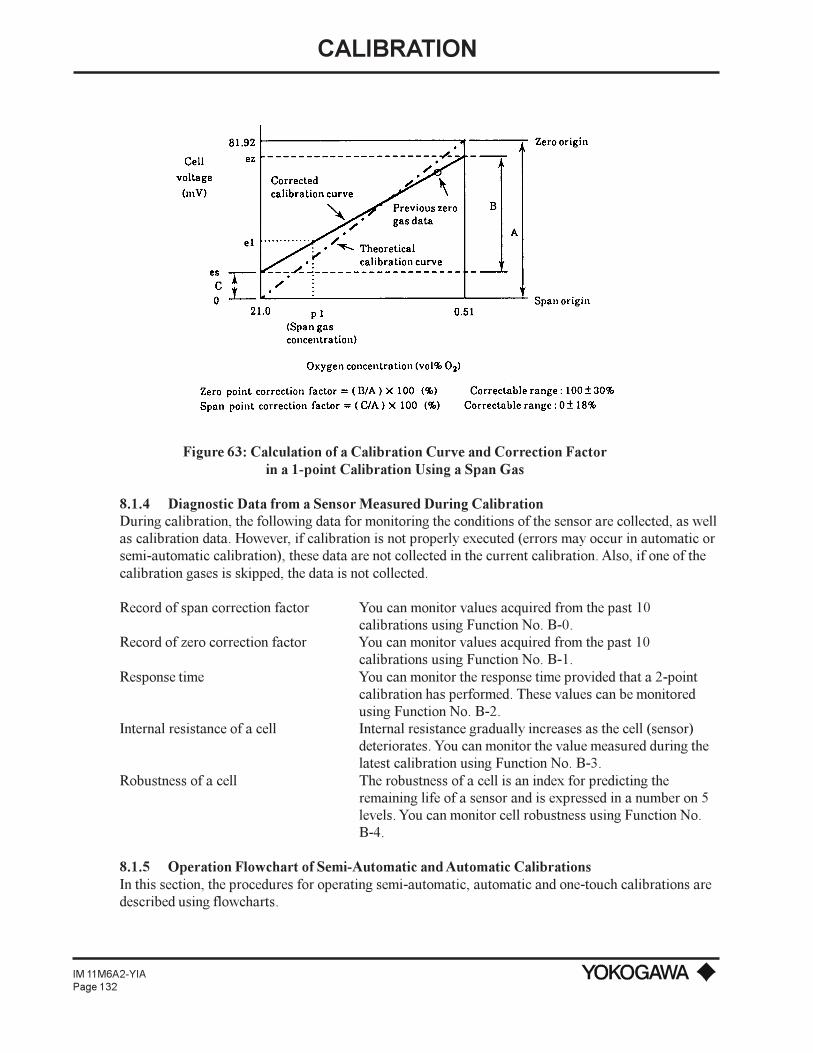
CALIBRATION
IM 11M6A2-YIAPage 132
Figure 63: Calculation of a Calibration Curve and Correction Factorin a 1-point Calibration Using a Span Gas
8.1.4 Diagnostic Data from a Sensor Measured During CalibrationDuring calibration, the following data for monitoring the conditions of the sensor are collected, as wellas calibration data. However, if calibration is not properly executed (errors may occur in automatic orsemi-automatic calibration), these data are not collected in the current calibration. Also, if one of thecalibration gases is skipped, the data is not collected.
Record of span correction factor You can monitor values acquired from the past 10calibrations using Function No. B-0.
Record of zero correction factor You can monitor values acquired from the past 10calibrations using Function No. B-1.
Response time You can monitor the response time provided that a 2-pointcalibration has performed. These values can be monitoredusing Function No. B-2.
Internal resistance of a cell Internal resistance gradually increases as the cell (sensor)deteriorates. You can monitor the value measured during thelatest calibration using Function No. B-3.
Robustness of a cell The robustness of a cell is an index for predicting theremaining life of a sensor and is expressed in a number on 5levels. You can monitor cell robustness using Function No.B-4.
8.1.5 Operation Flowchart of Semi-Automatic and Automatic CalibrationsIn this section, the procedures for operating semi-automatic, automatic and one-touch calibrations aredescribed using flowcharts.
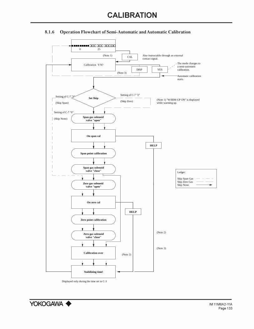
CALIBRATION
IM 11M6A2-YIAPage 133
8.1.6 Operation Flowchart of Semi-Automatic and Automatic Calibration
CAL
DISP YES
nnnnnnnnnooooooooooo
Calibration Y/N?
Also instructable through an external contact signal.
(Note 1)
(Note 3)
The mode changes toa semi-automatic calibration.
Automatic calibration starts.
(Note 1) "WARM-UP ON" is displayedwhile warming up.
Displayed only during the time set in C-3
0 25
Setting of C-7 "1"
(Skip Span)
Setting of C-7 "0"
(Skip None)
Setting of C-7 "2"
(Skip Zero)
(Note 2)
(Note 2)
(Note 3)
Ledger:
Skip Span GasSkip Zero GasSkip None
Span gas solenoid valve "open"
On span cal
HELP
Span point calibration
Span gas solenoidvalve "close"
Zero gas solenoid valve "open"
On zero cal
Set Skip
HELP
Zero point calibration
Zero gas solenoidvalve "close"
Calibration over
Stabilizing time!
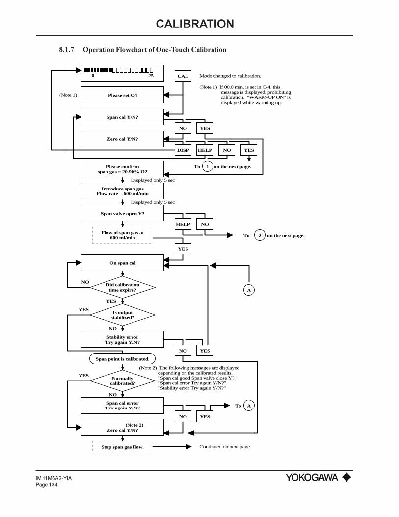
CALIBRATION
IM 11M6A2-YIAPage 134
Please set C4
Span cal Y/N?
Zero cal Y/N?
Please confirmspan gas = 20.90% O2
Introduce span gasFlow rate = 600 ml/min
Span valve open Y?
Flow of span gas at600 ml/min
On span cal
Stability errorTry again Y/N?
Span point is calibrated.
Normallycalibrated?
Span cal errorTry again Y/N?
(Note 2)Zero cal Y/N?
Stop span gas flow.
CAL
NO
YESDISP HELP NO
HELP
YES
NO
YES
NO YES
NO YES
(Note 2) The following messages are displayed depending on the calibrated results. "Span cal good Span valve close Y?" "Span cal error Try again Y/N?" "Stability error Try again Y/N?"
To A
Continued on next page
NO
Is outputstabilized?
YES
NO
NO
YES
YES
A
To on the next page.2
Displayed only 5 sec
Displayed only 5 sec
(Note 1)
Mode changed to calibration.
(Note 1) If 00.0 min. is set in C-4, this message is displayed, prohibiting calibration. "WARM-UP ON" is displayed while warming up.
1To on the next page.
Did calibrationtime expire?
0 25nnnnnnnnnooooooooooo
8.1.7 Operation Flowchart of One-Touch Calibration

CALIBRATION
IM 11M6A2-YIAPage 135
NO
YES
Span cal goodSpan valve close?
HELPNO
HELP NO
Zero valve open Y?
Did calibrationtime expire?
On zero cal
Zero point calibration
Normally calibrated?
Stability errorTry again Y/N?
Zero cal errorTry again Y/N?
Flow of zero gas at600 ml/min
Stop zero gas flow
(Note 3)Span cal Y/N?
YES
NO YES
NO YES
NO YES
Span cal Y/N?
Stabilizing time!
YES
Continued from the previous page
Please confirmzero gas = 01.00 % O2
2To
To 2
Introduce span gasFlow rate = 600 ml/min
1
Displayed only 5 sec
Displayed only 5 sec
YES
No
YES
YES
No
No
Is outputstabilized?
B
To
(Note 3) The following messages are displayed depending on the calibrated results. "Zero cal good Zero valve close Y?" "Zero cal error Try again Y/N?" "Stability error Try again Y/N?"
Displayed only during the time set in C-3
B
2
The one-touch calibration procedure above finishes.Select the function No. A-0 display by pressing themeasurement mode select key.
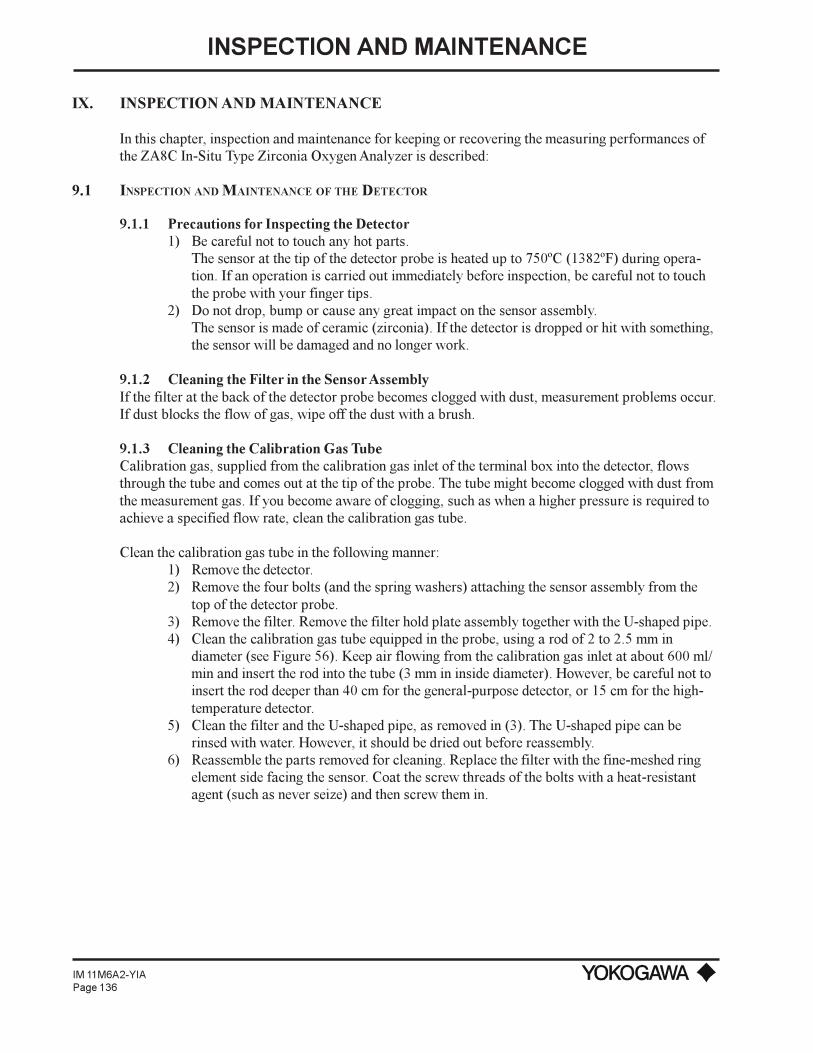
INSPECTION AND MAINTENANCE
IM 11M6A2-YIAPage 136
IX. INSPECTION AND MAINTENANCE
In this chapter, inspection and maintenance for keeping or recovering the measuring performances ofthe ZA8C In-Situ Type Zirconia Oxygen Analyzer is described:
9.1 INSPECTION AND MAINTENANCE OF THE DETECTOR
9.1.1 Precautions for Inspecting the Detector1) Be careful not to touch any hot parts.
The sensor at the tip of the detector probe is heated up to 750ºC (1382ºF) during opera-tion. If an operation is carried out immediately before inspection, be careful not to touchthe probe with your finger tips.
2) Do not drop, bump or cause any great impact on the sensor assembly.The sensor is made of ceramic (zirconia). If the detector is dropped or hit with something,the sensor will be damaged and no longer work.
9.1.2 Cleaning the Filter in the Sensor AssemblyIf the filter at the back of the detector probe becomes clogged with dust, measurement problems occur.If dust blocks the flow of gas, wipe off the dust with a brush.
9.1.3 Cleaning the Calibration Gas TubeCalibration gas, supplied from the calibration gas inlet of the terminal box into the detector, flowsthrough the tube and comes out at the tip of the probe. The tube might become clogged with dust fromthe measurement gas. If you become aware of clogging, such as when a higher pressure is required toachieve a specified flow rate, clean the calibration gas tube.
Clean the calibration gas tube in the following manner:1) Remove the detector.2) Remove the four bolts (and the spring washers) attaching the sensor assembly from the
top of the detector probe.3) Remove the filter. Remove the filter hold plate assembly together with the U-shaped pipe.4) Clean the calibration gas tube equipped in the probe, using a rod of 2 to 2.5 mm in
diameter (see Figure 56). Keep air flowing from the calibration gas inlet at about 600 ml/min and insert the rod into the tube (3 mm in inside diameter). However, be careful not toinsert the rod deeper than 40 cm for the general-purpose detector, or 15 cm for the high-temperature detector.
5) Clean the filter and the U-shaped pipe, as removed in (3). The U-shaped pipe can berinsed with water. However, it should be dried out before reassembly.
6) Reassemble the parts removed for cleaning. Replace the filter with the fine-meshed ringelement side facing the sensor. Coat the screw threads of the bolts with a heat-resistantagent (such as never seize) and then screw them in.
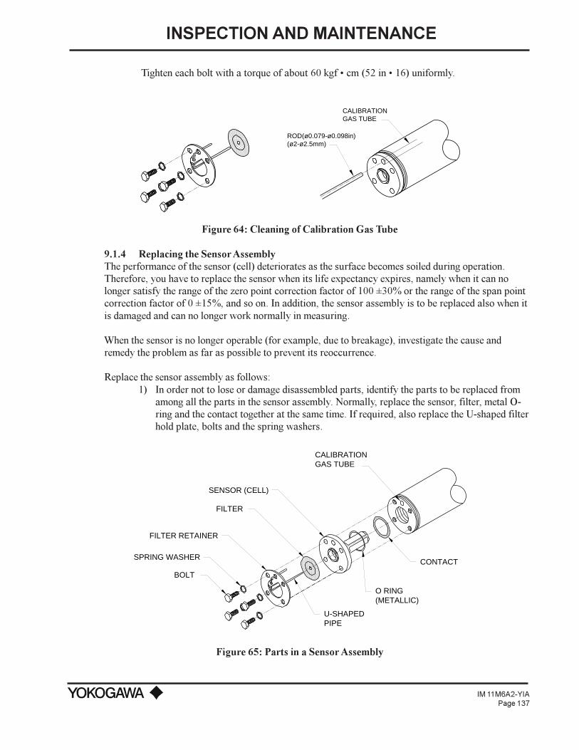
INSPECTION AND MAINTENANCE
IM 11M6A2-YIAPage 137
Tighten each bolt with a torque of about 60 kgf cm (52 in 16) uniformly.
ROD(ø0.079-ø0.098in)(ø2-ø2.5mm)
CALIBRATIONGAS TUBE
Figure 64: Cleaning of Calibration Gas Tube
9.1.4 Replacing the Sensor AssemblyThe performance of the sensor (cell) deteriorates as the surface becomes soiled during operation.Therefore, you have to replace the sensor when its life expectancy expires, namely when it can nolonger satisfy the range of the zero point correction factor of 100 ±30% or the range of the span pointcorrection factor of 0 ±15%, and so on. In addition, the sensor assembly is to be replaced also when itis damaged and can no longer work normally in measuring.
When the sensor is no longer operable (for example, due to breakage), investigate the cause andremedy the problem as far as possible to prevent its reoccurrence.
Replace the sensor assembly as follows:1) In order not to lose or damage disassembled parts, identify the parts to be replaced from
among all the parts in the sensor assembly. Normally, replace the sensor, filter, metal O-ring and the contact together at the same time. If required, also replace the U-shaped filterhold plate, bolts and the spring washers.
BOLT
SPRING WASHER
FILTER RETAINER
FILTER
SENSOR (CELL)
CALIBRATIONGAS TUBE
CONTACT
O RING(METALLIC)
U-SHAPEDPIPE
Figure 65: Parts in a Sensor Assembly

INSPECTION AND MAINTENANCE
IM 11M6A2-YIAPage 138
2) Remove the bolts from the back of the detector probe, together with the washers.3) Remove the filter hold plate with the U-shaped pipe. At this point, the filter can also be
separated from the detector probe.4) Remove the sensor and the metal O-ring (embedded in a groove on the flange surface of
the sensor). Pull the sensor out by twisting it slightly.5) Remove the contact using tweezers to pull it out of the groove.6) If you can use any of the parts from among those removed, clean them with solvent to
remove any contaminants adhering to them. Also, clean the parts used for mounting thedetector probe, as they may also be soiled with the measurement gas.
7) The parts are to be assembled sequentially. First, replace the contact. Being careful not tocause irregularities in the pitch of the coil spirals (i.e., not to bend the coil out of shape),place it in the ringed groove so that it forms a solid contact.
8) Next, set the metal O-ring in the O-ring groove on the flange surface of the sensor andthen mount the sensor. To insert the sensor, turn it clockwise. After inserting it all the wayto its base, adjust its position so that the U-shaped pipe insertion holes of the sensor andof the probe are properly aligned.
9) Replace the filter, the filter hold plate and the U-shaped pipe. To mount the U-shapedpipe, attach the pipe to the filter hold plate and then insert the assembly into the U-shapedpipe insertion hole. In addition, mount the filter with the fine-meshed ring-shaped elementside facing and forming a contact with the sensor.
10) Attach the reassembled parts with the four bolts. Coat the threads of the bolts with a heat-resistant agent (such as never seize) and then screw then in along with the washers.Tighten all four bolts with a torque of about 60 kgf cm (52 in lb).
The work of replacing the sensor assembly is now complete. Mount the detector and restart theoperation. However, be sure to calibrate the instrument before beginning a measurement.
9.1.5 Cleaning the High Temperature Probe AdapterThe high-temperature detector is structured so that the gas to be measured is directed toward thedetector with a high-temperature probe adapter. Therefore, if the probe or the sample gas outlet clogs,a precise measurement is no longer possible because of no gas flow. Therefore, if a high-temperaturedetector is used you must inspect it periodically and, if any part of it is significantly clogged with dust,clean it.
Dust sticking to the probe should be blown off. If any dust still remains after blowing, clean it with ametal rod. In addition, if dust is found on the auxiliary ejector at the sample gas outlet, remove theseparts from the high-temperature probe adapter and then clean them. To remove dust, blow them withair or rinse them with water. If the ejector is plugged, replace it with a new ejector. If the transporttube is clogged, remove particulates with a metal rod.
9.2 INSPECTION AND MAINTENANCE OF THE CONVERTER
You need not inspect or perform maintenance work on the converter daily or periodically. If theconverter fails to work properly, check for the correct input voltage or a brown fuse.
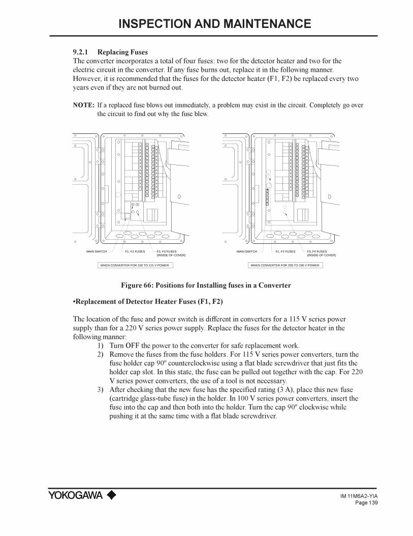
INSPECTION AND MAINTENANCE
IM 11M6A2-YIAPage 139
9.2.1 Replacing FusesThe converter incorporates a total of four fuses: two for the detector heater and two for theelectric circuit in the converter. If any fuse burns out, replace it in the following manner.However, it is recommended that the fuses for the detector heater (F1, F2) be replaced every twoyears even if they are not burned out.
NOTE: If a replaced fuse blows out immediately, a problem may exist in the circuit. Completely go overthe circuit to find out why the fuse blew.
MAIN SWITCH F1, F2 FUSES F3, F4 FUSES(INSIDE OF COVER)
WHEN CONVERTER FOR 100 TO 115 V POWER WHEN CONVERTER FOR 200 TO 240 V POWER
(INSIDE OF COVER)F3, F4 FUSESMAIN SWITCH F1, F2 FUSES
Figure 66: Positions for Installing fuses in a Converter
Replacement of Detector Heater Fuses (F1, F2)
The location of the fuse and power switch is different in converters for a 115 V series powersupply than for a 220 V series power supply. Replace the fuses for the detector heater in thefollowing manner:
1) Turn OFF the power to the converter for safe replacement work.2) Remove the fuses from the fuse holders. For 115 V series power converters, turn the
fuse holder cap 90º counterclockwise using a flat blade screwdriver that just fits theholder cap slot. In this state, the fuse can be pulled out together with the cap. For 220V series power converters, the use of a tool is not necessary.
3) After checking that the new fuse has the specified rating (3 A), place this new fuse(cartridge glass-tube fuse) in the holder. In 100 V series power converters, insert thefuse into the cap and then both into the holder. Turn the cap 90º clockwise whilepushing it at the same time with a flat blade screwdriver.

INSPECTION AND MAINTENANCE
IM 11M6A2-YIAPage 140
Replacing the fuse (F3, F4) to protect the electric circuit in a converter
1) Turn OFF the main switch of the converter to maintain safety while replacing the fuse.2) Remove the fuse. Fuses F3, F4 are cartridge socket types in which two prongs of the fuse
are inserted into the socket on the printed circuit board. If you cannot remove fuses F3,F4 easily with your hand, use a tool such as a long nose or needle nose pliers.
3) Check the new fuse for the specified rating (0.2 A) before installing it. Hold the body ofthe fuse gently with a pair of pliers and fully insert the two prongs into the socket on theprinted circuit board. Be careful not to bend the prongs during installation (otherwise, thefuse may be damaged).
9.2.2 Replacing the Message Display UnitThe dot matrix LCD, incorporated in the message display unit, should provide long term operation.However, over time, the performance deteriorates gradually and unavoidably (i.e., giving ambiguousreadouts, etc.). If the readout on the display becomes unreadable, replace the LCD assembly.
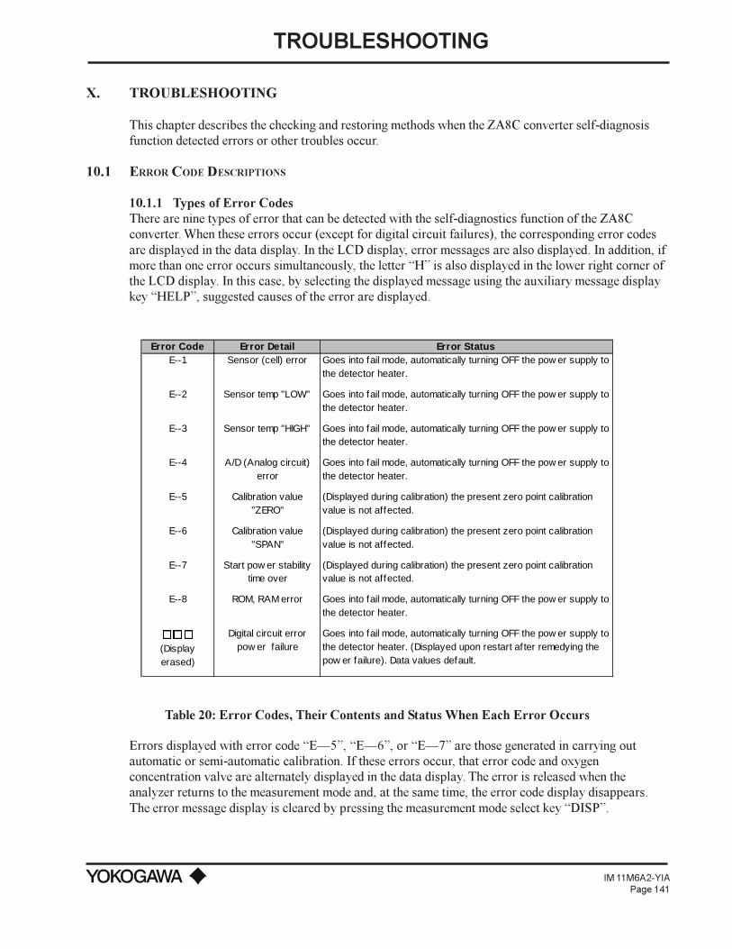
TROUBLESHOOTING
IM 11M6A2-YIAPage 141
X. TROUBLESHOOTING
This chapter describes the checking and restoring methods when the ZA8C converter self-diagnosisfunction detected errors or other troubles occur.
10.1 ERROR CODE DESCRIPTIONS
10.1.1 Types of Error CodesThere are nine types of error that can be detected with the self-diagnostics function of the ZA8Cconverter. When these errors occur (except for digital circuit failures), the corresponding error codesare displayed in the data display. In the LCD display, error messages are also displayed. In addition, ifmore than one error occurs simultaneously, the letter H is also displayed in the lower right corner ofthe LCD display. In this case, by selecting the displayed message using the auxiliary message displaykey HELP, suggested causes of the error are displayed.
Error Code Error Detail Error StatusE--1 Sensor (cell) error Goes into fail mode, automatically turning OFF the pow er supply to
the detector heater.
E--2 Sensor temp "LOW" Goes into fail mode, automatically turning OFF the pow er supply to the detector heater.
E--3 Sensor temp "HIGH" Goes into fail mode, automatically turning OFF the pow er supply to the detector heater.
E--4 A/D (Analog circuit) error
Goes into fail mode, automatically turning OFF the pow er supply to the detector heater.
E--5 Calibration value "ZERO"
(Displayed during calibration) the present zero point calibration value is not affected.
E--6 Calibration value "SPAN"
(Displayed during calibration) the present zero point calibration value is not affected.
E--7 Start pow er stability time over
(Displayed during calibration) the present zero point calibration value is not affected.
E--8 ROM, RAM error Goes into fail mode, automatically turning OFF the pow er supply to the detector heater.
ooo (Display erased)
Digital circuit error pow er failure
Goes into fail mode, automatically turning OFF the pow er supply to the detector heater. (Displayed upon restart af ter remedying the pow er failure). Data values default.
Table 20: Error Codes, Their Contents and Status When Each Error Occurs
Errors displayed with error code E5, E6, or E7 are those generated in carrying outautomatic or semi-automatic calibration. If these errors occur, that error code and oxygenconcentration valve are alternately displayed in the data display. The error is released when theanalyzer returns to the measurement mode and, at the same time, the error code display disappears.The error message display is cleared by pressing the measurement mode select key DISP.

TROUBLESHOOTING
IM 11M6A2-YIAPage 142
NOTE: Re-calibration after an error occurred should be performed after examining that set points and pipingconditions are not improper.
Errors displayed with error code E1, E2, E3, E4, or E8 including digital circuitfailure are caused by equipment failures. If these errors occur, the converter stops the supply of powerto the detector heater and holds the output signal at the value immediately before the error occurrence(preset value if 2 is set with function No. D-2). When these errors occur, turn off the converterpower and begin restoration. The error code display is released after the equipment is restored andoperates normally.
10.1.2 Causes of E1 Sensor (Cell) Failure and Procedure for Restoration
Causes1) Failure in wiring between the converter and the detector (poor contact of terminal connec-
tions, disconnection, etc.)2) Sensor (cell) assembly failure (damage, deterioration)3) Failure in the sensor (cell) assembly mounting part (poor continuity between the sensor
electrode and the contact, etc.)4) Wiring system failure inside the detector (disconnection, etc.)
Is an error displayed?
Turn off the power to the converter
End. Set temporary data.
Replace the wiring cables.
Is the sensor extremelydirty, corrosive, or damaged?
The analyzer operatesproperly.
YES
YES
YES
YES
YES
NO
NO
NO
NO
NO
NO
YESTemporarily operate
the analyzer bymounting the spare
sensor assembly.
Is there any breakageor poor contact in wiring to the
converter terminals?
Is there any place of disconnection or poor continuity in wiring between the converter
and detector?
Is there any breakageor poor contact in wiring to the
detector terminals?
*Remove the wiring conductors from detector terminals 1 and 2 and
short the conductors removed. Measure the resistance of this conductor on the
converter side. Resistance value is normal if it indicates 10 ohms or less.
*Examine the wiring connection toconverter terminals 3 and 4. If
the repeater terminal box is used, also check wiring connection there.
Replace the damaged parts.
Replace the damaged parts.
*Examine the wiring connection to detector terminals 1 and 2.
Also check that terminals and cableconductors are not corroded.
*Remove the sensor assembly from the detector and check for any corrosion that may cause poor contact between
the electrode and contact. Sensor assemblies with no failure may
be used againReplace the sensor assembly.
*Turn on the power switch to put the analyzer in operation.
Inside of the converter or detector is suspected of failure.
Contact Yokogawa.
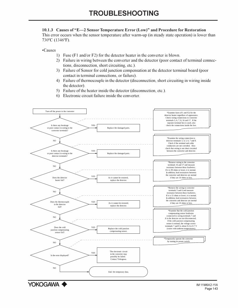
TROUBLESHOOTING
IM 11M6A2-YIAPage 143
10.1.3 Causes of E2 Sensor Temperature Error (Low) and Procedure for RestorationThis error occurs when the sensor temperature after warm-up (in steady state operation) is lower than730ºC (1346ºF).
Causes1) Fuse (F1 and/or F2) for the detector heater in the converter is blown.2) Failure in wiring between the converter and the detector (poor contact of terminal connec-
tions, disconnection, short circuiting, etc.).3) Failure of Sensor for cold junction compensation at the detector terminal board (poor
contact in terminal connections, or failure).4) Failure of thermocouple in the detector (disconnection, short circuiting in wiring inside
the detector).5) Failure of the heater inside the detector (disconnection, etc.).6) Electronic circuit failure inside the converter.
Turn off the power to the converter
Does the thermocouplein the detector
fail?
Does the detectorheater fail?
Is the error displayed?
Replace the cold junctioncompensating sensor.
End. Set temporary data.
YES
YES
YES
YES
YES
YES
NO
NO
NO
Does the coldjunction compensating
sensor fail?
NO
NO
NO
*Examine that the cold junction compensating sensor leadwires
connected to wiring terminals 7 and 8 in the detector are not disconnected.
If the cold junction compensating sensor is normal, the voltage across
terminals 7 and 8 is about 0.4 to 0.7 V (varies with ambient temperatures).
*Remove the wiring to converter terminals 5 and 6 and measure
resistance between these leadwires.If it is 15 ohms or lower, it is normal.In addition, lead resistances between the converter and detector are normal
if they are 10 ohms or less.
*Examine the wiring connection to detector terminals 3, 4, 5, 6, 7 and 8.
Check if the terminal and cable conductors are not corroded. Also
check that wiring is not short circuited between the converter and detector.
*Examine fuses (F1 and F2) for thedetector heater regardless of appearance.
Check wiring connections to converterterminals 5, 6, 7, 8, 16 and 17. If the
repeater terminal box is used, alsocheck the connections inside the box.Is there any breakage
or poor contact in wiring to theconverter terminals?
Is there any breakageor poor contact in wiring to the
detector terminals?
*Temporarily operate the converter by turning its power switch.
*Remove wiring to the converter terminals 16 and 17 and measure
resistance between these leadwires. If it is 90 ohms or lower, it is normal. In addition, lead resistances between the converter and detector are normal
if they are 10 ohms or less.
Replace the damaged parts.
Replace the damaged parts.
As it cannot be restored,replace the detector.
As it cannot be restored, replace the detector.
The electronic circuit in the converter may possibly be failed. Contact Yokogawa.

TROUBLESHOOTING
IM 11M6A2-YIAPage 144
10.1.4 Causes of E3 Sensor Temperature Error (High) and Procedure for RestorationThis error occurs when the converter detects that the sensor temperature is higher than 780ºC(1486ºF). It also occurs if the converter detects failure of the heater circuit and temperature measuringand controlling circuit during warm-up.
CausesIf the error code is displayed in steady state operation, the following are considered as the possiblecauses:
1) Cold junction compensating sensor failure at the detector terminal board.2) Failure of thermocouple in the detector.3) Failure of electronic circuits in the converter.
Next, if the error code is displayed during warm-up, the following are considered as the possiblecauses:
1) Fuses (F1 and/or F2) in the converter for the detector heater are blown.2) Wiring failure between the converter and the detector (poor contact at the terminal connec-
tions, disconnection, short circuiting, etc.).3) Failure of the heater in the detector (disconnection, etc.).
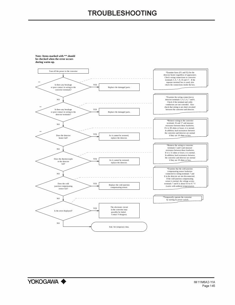
TROUBLESHOOTING
IM 11M6A2-YIAPage 145
Turn off the power to the converter
Does the thermocouplein the detector
fail?
Is the error displayed?
Replace the cold junctioncompensating sensor.
End. Set temporary data.
YES
YES
YES
YES
YES
YES
NO
NO
NO
Does the coldjunction compensating
sensor fail?
NO
NO
NO
Is there any breakageor poor contact in wiring to the
converter terminals?
**
**
Does the detectorheater fail?
**
Is there any breakageor poor contact in wiring to the
detector terminals?
*Examine fuses (F1 and F2) for thedetector heater regardless of appearance.
Check wiring connections to converterterminals 5, 6, 7, 8, 16 and 17. If the
repeater terminal box is used, alsocheck the connections inside the box.
*Examine the wiring connection to detector terminals 3, 4, 5, 6, 7 and 8.
Check if the terminal and cable conductors are not corroded. Also
check that wiring is not short circuited between the converter and detector.
*Remove the wiring to converter terminals 5 and 6 and measure
resistance between these leadwires.If it is 15 ohms or lower, it is normal.In addition, lead resistances between the converter and detector are normal
if they are 10 ohms or less.
*Examine that the cold junction compensating sensor leadwires
connected to wiring terminals 7 and 8 in the detector are not disconnected.
If the cold junction compensating sensor is normal, the voltage across
terminals 7 and 8 is about 0.4 to 0.7 V (varies with ambient temperatures).
*Temporarily operate the converter by turning its power switch.
Note: Items marked with ** shouldbe checked when the error occursduring warm-up.
Replace the damaged parts.
Replace the damaged parts.
As it cannot be restored,replace the detector.
*Remove wiring to the converter terminals 16 and 17 and measure
resistance between these leadwires. If it is 90 ohms or lower, it is normal. In addition, lead resistances between the converter and detector are normal
if they are 10 ohms or less.As it cannot be restored, replace the detector.
The electronic circuit in the converter may possibly be failed. Contact Yokogawa.

TROUBLESHOOTING
IM 11M6A2-YIAPage 146
10.1.5 Causes of E4 A/D (Analog Circuit) Failure and Procedure for RestorationThis error occurs when the electric circuit of the converter does not operate normally.
Causes1) The analog circuits of the converter contains a failure.2) The supply voltage significantly drops (15% or more of the rating).
Locating the Failures and Measures
Turn the converter power switch off and back on again. Next, check to see if operation is normal.
If operation is normal, the error is considered to be caused by temporary failure of the power system,such as voltage drop or influence of noise. If the cause is clear, take suitable measures to preventreoccurrence of the same problem.
If the error occurs again, it may be caused by the converters electric circuits, such as a CPU card. Inthis case, it is not as easy to locate and restore the failed part. If the error occurs again, contactYOKOGAWA INDUSTRIAL AUTOMATION. However, first confirm by checking the power supplythat the power system is not at fault.
10.1.6 Causes of E5 Calibration Value Error (Zero) and Procedure for RestorationThis error occurs when the zero point correction factor exceeds the range 100 ±30% in the automaticand semi-automatic calibrations.
Causes1) The oxygen concentration of zero gas and the value set with function No. C-1 do not
agree or the span gas is accidentally used as the zero gas.2) The zero gas does not flow by the specified quantity (about 600 ml/min).3) The sensor (cell) is damaged and the cell emf contains an error.
Locating the Cause of Failure and Taking Measures1) To make sure, carry out the calibration once more. Before calibration, examine the
following. If they are not in normal state, correct them.Does the value set in the function No. C-1 agree with the zero gas oxygen concentration?Does the calibration gas tubing have measures to no zero gas leakage?
2) If the error does not occur in re-calibration, it is considered as the cause of the error inthe first calibration that the calibrating conditions were not proper. In this case, noparticular restoration is necessary. Restart the steady state operation. If the error alsooccurs in re-calibration, it is considered as the cause of error occurrence that the sensor isdeteriorated or is damaged. Confirm that the error corresponds to one or more of thefollowing phenomena and replace it with a new sensor (see 10.1.4).When zero gas is passed, the sensor (cell) emf indicated with function No. A-3 greatlydiffers from the theoretical value in that oxygen concentration.When three kinds of gas (zero gas, span gas, and the gas having approximately middleoxygen concentration between the above two) are measured, correlation cannot be foundin these measured data for oxygen concentration.

TROUBLESHOOTING
IM 11M6A2-YIAPage 147
In addition, check the sensor deterioration for damage which caused the error occurrencewhether or not it abruptly occurs by the following phenomena. If abrupt occurrence maybe suspected, check the check valve located at the inlet of detector calibration gaseswhether or not the valve has failed. Check valve failure causes condensed water in thecalibration gas tubing, which is the cause of sensor breakage.Examine historical data of the zero point correction factor displayed with function No.B-1. Permissible range of the zero point correction factor is 100 ±30%.Examine the sensor (cell) internal resistance displayed with function No. B-3. A newsensor shows the value of 200 ohms or less. While the dissipated sensor approaching tothe end of the life indicates the value of 3 to 10 k ohms.Examine the sensor integrity data (five grade evaluation of five to one) displayed withfunction No. B-4. A sensor in good state shows 5.
10.1.7 Causes of E6 Calibration Value Error (Span) and Procedure for RestorationThis error occurs when the span point correction factor exceeds the range 0 ±18% in the automaticand semi-automatic calibrations.
Causes1) The oxygen concentration of span gas and the value set with function No. C-0 do not
agree or the zero gas is accidentally used as the span gas.2) The span gas does not flow by the specified quantity (about 600 ml/min).3) The sensor (cell) is damaged and the cell emf contains an error.
Locating the Cause of Failure and Taking Measures1) To make sure, carry out the calibration once more. Before calibration, examine the
following. If they are not in normal state, correct them.Does the value set in the function No. C-0 agree with the span gas oxygen concentration?Is there a leak in the span gas tubing or connections?
2) If the error does not occur in re-calibration, it is considered as the cause of the error in thefirst calibration that the calibration conditions were not proper. In this case, no particularrestoration is necessary. Restart the steady state operation.
If the error also occurs in re-calibration, it is considered as the cause of error occurrence that thesensor has deteriorated or is damaged. Confirm that the error corresponds to one or more of thefollowing phenomena and replace it with a new sensor (see section 10.1.4).
1) When span gas is passed, the sensor (cell) emf indicated with function No. A-3 greatlydiffers from the theoretical value in that oxygen concentration.
2) When three kinds of gas (zero gas, span gas, and the gas having approximately middleoxygen concentration between the above two) are measured, correlation cannot be foundin these measured data for oxygen concentration. In addition, check the sensor deteriora-tion or damage which caused the error occurrence may be suspected, check the checkvalve located at the inlet of the detector calibration gases whether or not the valve hasfailed. Check valve failure causes condensed water in the calibration gas tubing, which isthe cause of sensor breakage.Examine historical data of the span point correction factor displayed with function No.B-0. Permissible range of the span point correction factor is 0 ±18%.Examine the sensor (cell) internal resistance displayed with function No. B-3. A newsensor shows the value of 200 ohms or less.

TROUBLESHOOTING
IM 11M6A2-YIAPage 148
3) While the displayed sensor approaching to the end of the life indicates the value of 3 to 10k ohms.Examine the sensor integrity data (five grade evaluation five to one) displayed withfunction No. B-4. A sensor in good state shows 5.
10.1.8 Causes of E7 EMF Stabilization Time Over and Procedure for RestorationThis error occurs when the sensor (cell) emf is not stabilized even if the calibration time is overbecause the sensor part of the detector is not filled with calibration gas (zero and span gases) at theone-touch calibration.
Causes1) Flow of the calibration gas is small (specified flow: about 600 ml/min).2) Measuring gas flows toward the tip of the detector probe.3) Sensor (cell) response is deteriorated.
Locating the Cause of Failure and Taking Measures1) Examine the setting time with function No. C-4 whether or not it is suitable. If not
suitable, modify the setpoint and perform re-calibration again. Carry out re-calibrationafter confirming that the tubing does not leak and flowing calibration gas by the specifiedrate (about 600 ml/min).
2) When calibration is normally carried out, continue the steady state operation.If the error occurs again, replace the sensor assembly after checking that whether or notthe error corresponds to the following.Dust significantly sticks to the detector probe tip. If dust sticks, clean it (see Chapter 10).If the error occurs in calibration even after the sensor assembly is replaced, influence ofmeasuring gas flow is considered as the cause. If this occurs, stop the measuring gas formflowing toward the detector probe tip by changing the mounting position of the detector.
10.1.9 Causes of E8 ROM and RAM Failure and Procedure for RestorationThis error occurs when ROM contents reading and/or writing memory to RAM are not possible.
Causes1) ROM and RAM pins are not fully inserted into the socket.2) High supply voltages exceeding the specifications are applied or the effect of noise is
given to ROM and RAM.3) ROM and/or RAM failed.4) Failure occurred in digital circuits on the CPU board and others.
Locating the Cause of Failure and Taking Measures
Turn off the converter power switch. After confirming that the supply voltage satisfies thespecification, turn on the power switch again to operate the converter.
If the error repeats, repair is necessary. Contact Yokogawa Industrial Automation.
10.1.10 Causes of Display Disappearance (Data Display) and Procedure for RestorationOperation of the converter digital circuits is being self-checked with the watchdog timer (WDT) orclock monitor.

TROUBLESHOOTING
IM 11M6A2-YIAPage 149
This error occurs when power is turned on again after power supply to the converter electrical circuitis interrupted due to power failure, when the electrical circuit is interrupted due to power failure, orwhen the converter digital circuits fail, such as time-up of the watchdog timer normally reset in a fixedperiod. In any case, if the error occurs, on-screen information in the data display disappears.
Next, measures when the error occurs due to the digital circuit operation failure will be described.
Causes1) Low supply voltages exceeding the specifications are applied or the effect of noise is given
to digital circuits.2) Digital circuit failure.
Locating the Cause of the Failure and Taking Measures
Once the converter is turned off, the likelihood of explosion is eliminated. Make sure the supplyvoltage satisfies the specification and then turn on the power switch on to begin operation of theconverter.
If the error occurs again, repair is necessary. Contact Yokogawa Industrial Automation.
10.2 Measures When Measured Value Shows an Error
When measured values are abnormal, the cause is not always due to instrument failure. There aremany cases when the measuring gas itself is in an abnormal state or external causes, which disturb theinstrument operation, exist. In this section, we present cases where measured values show thefollowing phenomena:
1) The measured value is higher than the true value.2) The measured value is lower than the true value.3) The measured value sometimes show abnormal values.
10.2.1 Measured Value Higher Than True ValueCauses and Measures
1) The measuring gas pressure becomes higher.The measured oxygen concentration value X (vol% O2) is expressed as shown below,when the measuring gas pressure is higher than that in calibration by ∆p (mm H20).X=Y [1 + (∆p/10336)]where Y: Measured oxygen concentration value at the same pressure as in calibration(vol% O2).When an increment of the measured value by pressure change cannot be neglected, mea-sures must be taken.
Investigate the following points to perform improvement available in each process.Is improvement in facilitys aspect available so that pressure change does not occur?Is performing calibration available under the averaging measuring gas pressure (internalpressure of a furnace)?

TROUBLESHOOTING
IM 11M6A2-YIAPage 150
2) Moisture content in a reference gas changes (increase) greatly.When this error is not ignored, use a gas in which moisture content is constant such asinstrument air in almost dry condition as a reference gas.In addition, change of moisture content in exhaust gas after combustion is also consideredas a cause of error. However, normally this error is negligible.
3) Calibration gas (span gas) is mixing into the detector due to leakage.If the span gas is mixing into the detector due to leakage for the reason of failure of thevalve provided in the calibration gas tubing system, the measured value shows a value alittle higher than normal.Check valves in the calibration gas tubing system for leakage. For manual valves, checkthem after confirming that they are in a fully closed state.
4) The reference gas is mixing into the measuring gas and vice versa.Since the difference between oxygen partial pressures on the sensor anode and cathodesides becomes smaller, the measured value shows a higher value.An error which does not appear as the error E1 may occur in the sensor. Visuallyinspect the sensor. If any crack is recognized, replace it with a new sensor assembly.
5) The fly ash filter is clogged with ash, and requires replacement.
NOTE: Data such as cell integrity displayed with function No. B-4 should also be used for deciding sensorquality.
10.2.2 Measured Value Lower Than True ValueCauses and Measures
1) The measuring gas pressure becomes lower.Where an increment of the measured value by pressure change cannot be neglected,follow the steps as described in subsection 10.1.1 (1).
2) Moisture content in a reference gas changes (decreases) greatly.If air at the detector installation site is used for the reference gas, a large change ofmoisture in the air may cause an error in measured oxygen concentration value (vol%O2). To correct this error, use a gas with little or no moisture content. Another cause oferror may be the sudden change in moisture content of the exhaust gas after combustion.However, normally this error is negligible.
3) Calibration gas (zero gas) is mixed into the detector due to leakage.If zero gas leakage into the detector is the cause of failure, the measured value will showa value a lower than normal. Check the valves in the calibration gas tubing system forleakage. For manual valves, check them after confirming that they are in fully closedstate.
10.2.3 Measured Value Sometimes Show Abnormal ValuesCauses and Measures
1) Noise is mixed into the converter from the detector output wiring.Shield the wiring to eliminate noise mixing into the converter.
2) The converter is affected with noises from the power supply.Insert the line filter in the power line.
3) The cell leads are incorrectly wired on the signal cable.4) The calibration gas for zero gas may not correspond to the certified value listed on the
cylinder. Reprogram menu C-1 and calibrate the sensor.
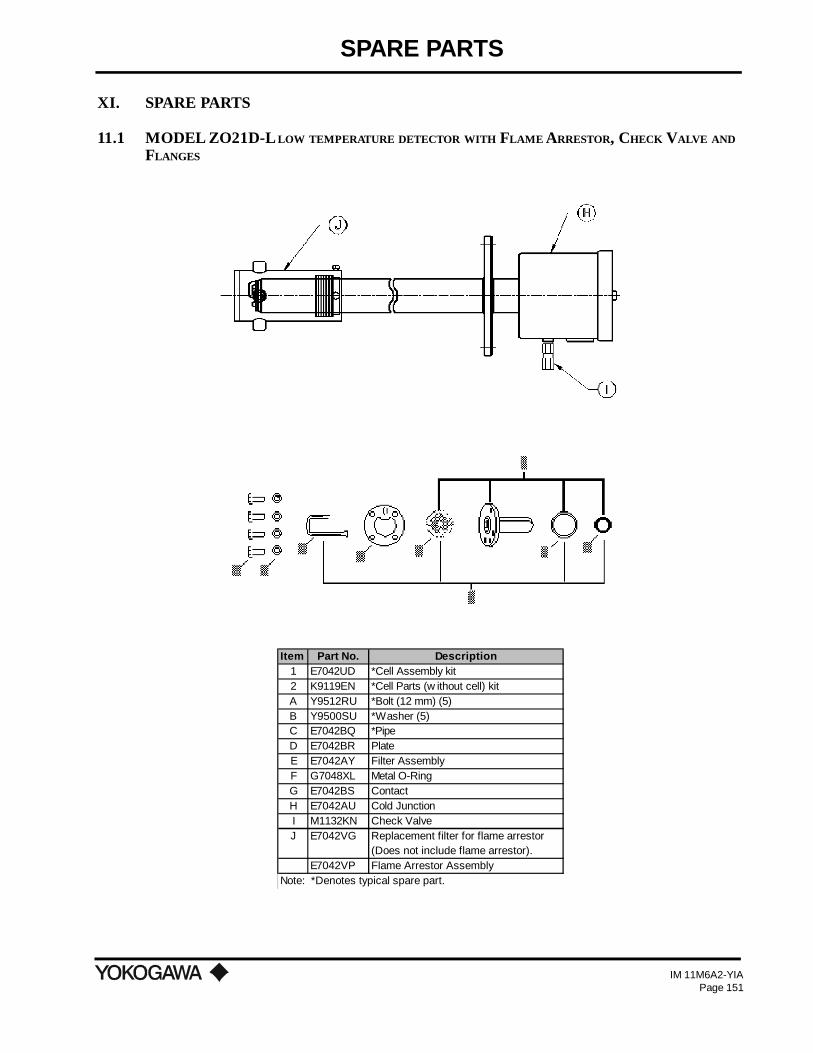
SPARE PARTS
IM 11M6A2-YIAPage 151
XI. SPARE PARTS
11.1 MODEL ZO21D-L LOW TEMPERATURE DETECTOR WITH FLAME ARRESTOR, CHECK VALVE ANDFLANGES
Item Part No. Description1 E7042UD *Cell Assembly kit2 K9119EN *Cell Parts (w ithout cell) kitA Y9512RU *Bolt (12 mm) (5)B Y9500SU *Washer (5)C E7042BQ *PipeD E7042BR PlateE E7042AY Filter AssemblyF G7048XL Metal O-RingG E7042BS ContactH E7042AU Cold JunctionI M1132KN Check ValveJ E7042VG Replacement filter for flame arrestor
(Does not include flame arrestor).E7042VP Flame Arrestor Assembly
Note: *Denotes typical spare part.

SPARE PARTS
IM 11M6A2-YIAPage 152
11.2 MODEL ZO21P ADAPTER TEE SPARE PARTS
Part Number Description
M1100HH Adapter Tee (ZO21P-H)M1132FH Adapter Tee (ZO21P-F)M1100HF PlateM1133FT Gasket (JIS 5K32A) for ZO21P-H, T, S or CM1132HP Gasket (3" ANSI) for ZO21P-FY9121BU NutY9120WU WasherM1132KY Bolt
11.3 ZA8C SPARE PARTS
1/4 FNPT
(Ø6
0) 4 - ø0.63(ø16.0) HOLES
ON A 3.54 (89.9) DIABOLT CIRCLE
3/4 FNPT
6.1
9.71
1.7
NOTES:1. MATERIAL IS 316 SST, EXCEPT FOR ANSIFLANGE WHICH IS 304 SST.
2. WEIGHT: 24.3 LBS(11 Kg)
(ø114.3)0.38(9.7) THK FLANGE
(193)
(ø22
8.6)
8 - ø0.75(4819.1) HOLESON A 7.50(190.5)DIABOLT CIRCLE0.94(23.8) THK FLANGE4" ANSI 150#RAISED FACE FLANGE
(297)
(246)
Ø2
.4
(155)
(2 PLACES)
[1.0
m]
7.60
ø9.
00
3.3F
T
ø4.50
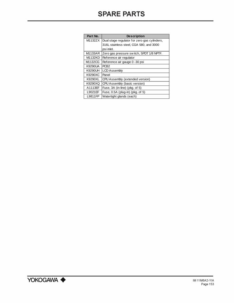
SPARE PARTS
IM 11M6A2-YIAPage 153
Part No. DescriptionM1132ZX Dual stage regulator for zero gas cylinders,
316L stainless steel, CGA 580, and 3000 psi inlet.
M1133AR Zero gas pressure sw itch, SPDT 1/8 NPTF.M1132KD Reference air regulator M1132CG Reference air gauge 0 -30 psiK9290UA PCB2K9290UH LCD AssemblyK9290XC PanelK9290XL CPU Assembly (extended version)K9290XQ CPU Assembly (basic version)A1113EF Fuse, 3A (in-line) (pkg. of 5)L9021EF Fuse, 0.5A (plug-in) (pkg. of 5)L9811FP Watertight glands (each)

APPENDIX A
IM 11M6A2-YIA
APPENDIX A. FIGURES AND TABLES
A.1 FIGURES
Figure Description Page Number
Figure 1 Typical System Configuration ............................................................................... 2Figure 2 ZA8C ..................................................................................................................... 4Figure 3 MC1 Manual Calibration Unit ............................................................................ 10Figure 4 AC1 Automatic Calibration Unit ......................................................................... 12Figure 5 ZO21D-L Standard Detector ............................................................................... 14Figure 6 ZO21D Detector w/ Tri Clamp ........................................................................... 15Figure 7 ZO21D-H High Temperature Detector w/150# JIS flange and junction box ...... 18Figure 8 ZO21D-H High Temperature Detector with junction box and flange ................. 19Figure 9 ZO21P-H High Temperature Adapter tee ............................................................ 21Figure 10 ZO21P-F High Temperature Adapter for the Flame Arrestor ............................. 21Figure 11 Water Eductor Assembly ..................................................................................... 24Figure 12 Auxiliary Ejector Assembly ................................................................................. 25Figure 13 Pressure Compensating Oxygen Detector ........................................................... 27Figure 14 Probe Protector .................................................................................................... 32Figure 15 Probe Support ...................................................................................................... 34Figure 16 Check Valve ......................................................................................................... 33Figure 17 Filter and Dust Guard.......................................................................................... 34Figure 18 Fly Ash Filter ....................................................................................................... 34Figure 19 WZ.../QC or /QF ................................................................................................. 36Figure 20 ZO21D.../A ......................................................................................................... 36Figure 21 Probe Insertion Hole ............................................................................................ 39Figure 22 Parts in Sensor Assembly .................................................................................... 41Figure 23 Dust Filter and Guard.......................................................................................... 41Figure 24 Fly Ash Filter ....................................................................................................... 42Figure 25 ZO21D with probe support (ZO21V) ................................................................. 43Figure 26 ZO21D with probe protector (ZO21R) ............................................................... 43Figure 27 ZO21PH High Temperature Tee Adapter ............................................................ 44Figure 28 Installation into probe insertion hole ................................................................... 45Figure 29 ZO21P High Temperature Adapter Tee ............................................................... 46Figure 30 Pipe Mounting Procedure .................................................................................... 48Figure 31 Drilling Mounting Holes...................................................................................... 48Figure 32 Mounting to the Wall ........................................................................................... 48Figure 33 Panel Cut Dimensions ......................................................................................... 49Figure 34 Mounting to the Panel ......................................................................................... 49Figure 35 MC1 Piping ......................................................................................................... 51Figure 36 AC1 Piping .......................................................................................................... 53Figure 37 AC1 Piping .......................................................................................................... 54Figure 38 ZA8C ................................................................................................................... 57Figure 39 Power Wiring ....................................................................................................... 58Figure 40 Case Ground Wiring ............................................................................................ 59Figure 41 Detector Signal Output -112ºF ( -80ºC) or less ambient ..................................... 60Figure 42 Detector Signal Output - Between 176º and 302ºF (80º and 150ºC) .................. 60

APPENDIX A
IM 11M6A2-YIA
Figure 43 Detector Heater Output - Maximum 112ºF (80ºC) ambient................................ 61Figure 44 Detector Heater Output - Between 176º and 302ºF (80º and 150ºC) .................. 61Figure 45 Quick Disconnect ................................................................................................ 62Figure 46 Wiring for Analog Output ................................................................................... 62Figure 47 Interconnect Wiring for AC1 & ZA8C ................................................................ 63Figure 48 Interconnect Wiring for 220 V AC ZA8C & AC1............................................... 64Figure 49 Contact Output Wiring ........................................................................................ 64Figure 50 ZA8C Relational Diagram .................................................................................. 66Figure 51 Contact Input Wiring ........................................................................................... 66Figure 52 Measurement Gas Temperature Input ................................................................. 67Figure 53 Oxygen Concentration ......................................................................................... 89Figure 54 Relationship between range and logarithmic output signal (4-20 mADC) .......... 90Figure 55 Span Point Correction Ratio................................................................................ 91Figure 56 Calculation of response time ............................................................................... 92Figure 57 Absolute Humidity of Air .................................................................................. 114Figure 58 Wiring of RS-232C Communications Cable ..................................................... 119Figure 59 Connections for RS-422A Communications...................................................... 120Figure 60 Connections for RS-422A Communications (when using an I/O isolating computer) ... 120Figure 61 O2 Concentration in Measurement Gas vs Cell Voltage (21.0% O
2 Equivalent) ...... 130
Figure 62 Calculation of a Calibration Curve and Correction Factor in a 2-point CalibrationUsing Zero and Span Gases .............................................................................. 131
Figure 63 Calculation of a Calibration Curve and Correction Factor in a 1-point CalibrationUsing a Span Gas .............................................................................................. 132
Figure 64 Cleaning of Calibration Gas Tube ..................................................................... 138Figure 65 Parts in a Sensor Assembly ............................................................................... 138Figure 66 Positions for Installing fuses in a Converter...................................................... 140
A.2 TABLES
Table 1 Approximate Weight of ZO21D detector w/4", 150# ANSI flange ..................... 15Table 2 Material Reference Chart for Transport Tubes ................................................... 22Table 3 Probe lengths and weights for ZO21DW ............................................................ 28Table 4 ZO21DW Accessories ......................................................................................... 29Table 5 Length and Weight of ZO21R-L probe protector w/4", 150# ANSI flange ........ 31Table 6 Quick Disconnect Cable Specifications............................................................... 38Table 7 Mounting parts required ...................................................................................... 40Table 8 Piping ................................................................................................................... 52Table 9 Wiring Channels .................................................................................................. 57Table 10 Specifications of Signal and Heater Cables ........................................................ 59Table 11 Contact States Classified with Relay Operation and Types of Contact .............. 65Table 12 Contact Input ON/OFF Electrical Parameters .................................................... 66Table 13 Diagnostic Values ................................................................................................ 74Table 14 Configurable Items and Their Defaults ............................................................... 97Table 15 Various Values and Fuels ................................................................................... 112Table 16 Error Codes, Details and Status ........................................................................ 116Table 17 Example of Items for Periodic Inspection ......................................................... 117Table 18 Setup Parameters for Calibration ...................................................................... 118Table 19 Communication Specifications .......................................................................... 121Table 20 Error Codes, Contents and Status ..................................................................... 141