instruction - atlatt.comatlatt.com/.../kansai/fbx_instructions.pdf · read and study this...
TRANSCRIPT

INSTRUCTION
Industrial Sewing Machines
FBX-PA-2AC
Third edition : April 2006
No. 060058

FFBBXXsseerr iieess
INTRODUCTION Thank you very much for purchasing Kansai Special FBX series. Read and study this Instruction Manual carefully before you start any of the procedure and save it for later use.
1. This Instruction Manual is for adjustments and maintenance procedures on only
Kansai Special FBX machine.
2. Check if pulley cover and safety cover, etc. are all securely set before you start the
machine.
3. Be sure to turn off the power in the time of adjusting, cleaning, threading the
machine, and replacing needles.
4. Never start the machine without oil in the reservoir.
5. Refer to the parts list as well as Instruction Manual before preventive maintenance.
6. The contents here are subject to change without notice.
Ind i ca t i on o f Ser ia l Number
Model
0 6 0 0 0 0 1
Manufacturing Year
Serial Number

FFBBXXsseerr iieess
CONTENTS
1. SPECIFICATIONS 1-1 Stitch type ··············································· 1 1-2 Model ····················································· 1 1-3 Specification ·········································· 1 1-4 Motor and power ······································ 1
2. NEEDLES AND THREADING 2-1 Needles ··················································· 2 2-2 Replacing needles ····································· 2 2-3 Threading ··············································· 2
3. SEWING SPEED 3-1 Sewing speed and motor direction ··············· 4
4. LUBRICATION 4-1 Oil ························································· 4 4-2 Lubrication ············································· 4 4-3 Replacing oil and oil element ······················ 5
5. TIMING AND ADJUSTMENT BETWEEN UPPER AND LOWER SHAFT··················· 6
6. TIMING OF LOOPER AND NEEDLE 6-1 Looper angle and looper holder bracket ······· 7 6-2 Timing of looper and needle ······················· 8 6-3 Looper gauge ··········································· 9 6-4 Needle height ·········································· 9
7. RETAINER LOOPER 7-1 Front-Back position ································ 10 7-2 Left-Right position ································· 10 7-3 Height of retainer looper ························· 10 7-4 Timing against needle ····························· 11
8. CLEARANCE BETWEEN NEEDLE AND NEEDLE GUARD ·························· 12
9. THREAD RECEIVER ······························ 12
10. FEED DOG AND STITCH LENGTH 10-1 Left-Right position of feed dog ················ 13 10-2 Front-Back position of feed dog ··············· 13 10-3 Height of feed dog ································· 13 10-4 Stitch length ········································ 14
11. NEEDLE FEED 11-1 Front-Back position of needle ················· 15 11-2 Amount of needle feed movement ············ 15
12. PRESSER FOOT 12-1 Pressure of presser foot ························· 16 12-2 Position of presser foot ·························· 16 12-3 Foot lift ··············································· 16
13. REAR PULLER 13-1 Height of rear puller ······························ 17 13-2 Puller pressure ····································· 17 13-3 Feeding amount of rear puller ················· 18 13-4 Tension of puller chain ···························· 18
14. STITCH FORMATION 14-1 Thread tension adjustment ····················· 18 14-2 Position of needle thread eyelet ··············· 19 14-3 Position of looper thread take-up eyelet ···· 19 14-4 Silicon tank ·········································· 20
15. CLEANING MACHINE ··························· 20
16. WAISTBAND CUTTER 16-1 Position and pressure ···························· 21 16-2 Speed ·················································· 21 16-3 Replacing cutter ···································· 21
17. DIRECT MOTOR 17-1 Direct motor ········································· 22 17-2 Gear box ·············································· 22 17-3 Universal Joint ····································· 22
18. SWITCH BOX 18-1 Switch box ··········································· 23
19. PROGRAMMING 19-1 Parameter of each parts ························· 24 19-2 Setting of parameter ······························ 25 19-3 Parameter list ······································ 27
20. SENSITIVITY OF BEAM SENSOR ········· 28 21. LAYOUT OF AIR PIPES ·························· 29

1 FFBBXXsseerr iieess
【1】SPECIFICATIONS 1-1 Stitch Type
JIS401 double chain stitch machine
1-2 Model Model FBX1102PA-2WAC
No. of needle 2 needles 4 needle threads No. of threads 4 looper threads
Type of tension set Mounted Type Min. gauge width 25.4mm Max. gauge width 38.1mm
1-3 Specification
PA-2AC is automation machine for attaching waistband only. The machine includes the below extra features; - Feeding pullers driven by pulse motor - Waistband cutting knife - Automatic skip stitch device
■Motors driven by pulse motors
Both Front puller (1st puller) and Back puller (2nd puller) are driven by pulse motor, whose timing of feeding is synchronized with the one of feed dog on machine head.
■Waistband cutting knife
Fabric edge of starting and ending are cut by cutting knife operated by pneumatic cylinder. Two sensors (Front and Back) are equipped on the machine, cutting knife is operated by the signal of those sensors. Machine speed is reduced to certain speed at the time of cutting process on both starting edge and ending edge.
■Automatic skip stitch device
Auto skip device can be operated at the starting and ending point of waistband. It is pneumatic device operated by signal of front and back sensors as well as cutting knife.
1-4 Motor and Power
Direct motor is used for this machine. Its voltage of power supply is only AC220V.
< Specification > Power source : AC220V

2 FFBBXXsseerr iieess
【2】NEEDLES AND THREADING 2-1 Needles
DV×57 of Schmetz or Organ Select the proper needle for the fabric and thread. (Standard #21) < Needles and needle size >
Schmetz DV×57 Nm90~Nm200
Organ DV×57 #14~#25
2-2 Replacing needles
When replacing the needle, check the needle carefully to see that the scarf is turned to the left of the machine (see the illustration).
2-3 Threading Thread the machine correctly by referring to pages 2 to 3. Incorrect threading may cause skip stitching, thread breakage and/or uneven stitch formation. When threading the looper, tilt the looper holder toward the front of the machine using the looper drawing bar.
■ To tilt the looper toward the front
1. Bring needle bar A to the top of its stroke.
2. Pay out the needle thread from the spool by pressing a finger down on needle threads B.
3. Open looper eyelet. 4. Pull drawing lever D out to the
arrow mark as shown in the illustration so that the looper holder is tilted toward the front of machine.
5. After the machine is threaded, replace the looper by pressing looper holder E into the machine until it clicks.
< Note > When replacing the needle, be sure to turn off the machine. A clutch motor continues running for a while after the machine is turned off. Therefore keep on pressing the pedal until the machine stops.
< Note > The looper pops out of the machine as soon as lever D is pulled, so do not bring your fingers close to the looper.

3 FFBBXXsseerr iieess
■ FBX-PA-2AC type

4 FFBBXXsseerr iieess
【3】SEWING SPEED 3-1 Sewing speed and motor direction
Refer to the table below for maximum and standard speeds of the Series. To extend machine life, run the machine approximately 15~20% below the maximum speed for the first 200 hours of operation (approx. 1 month). Then run the machine at the standard speed. The machine pulley turns counterclockwise as seen from the end of the machine pulley.
< Machine speed >
Model Maximum speed Standard speed
FBX-PA-2AC 4,000rpm 3,500rpm
【4】LUBRICATION
4-1 Oil Use Kansai Special’s genuine oil. (Part No. 28-613:1,000cc)
4-2 Lubrication
Remove rubber plug A from the oil hole. Fill the machine with oil until the oil level is at the top line (see H in the illustration) on oil gauge C. After the first lubrication, add oil so that the oil level will be between H and L. After filling the machine with oil, run the machine to check the oil is splashing onto oil pot A.

5 FFBBXXsseerr iieess
4-3 Replacing oil and oil element To extend machine life, be sure to replace the oil after the first 250 hours of operation. To replace the oil, follow the procedures below. 1. Remove the V belt from the motor pulley and
then remove the machine from the table. 2. Remove screw D and then drain the oil.
Be careful not to stain V belt with the oil. 3. After draining the oil, be sure to tighten screw
D. 4. Fill the machine with oil by referring to 4-2
shown above.
If element E is contaminated, proper oiling may not be performed. Clean the filter element every six months. If just a little or no oil flows out from the nozzle with the proper amount of oil in the machine, check the element. To do so, remove oil filter cap F. Replace the element if necessary.
< Note > Be careful to oil dropping when oil filter cap is removed. Oil may come out from oil element.

6 FFBBXXsseerr iieess
【5】TIMING AND ADJUSTMENT BETWEEN UPPER AND LOWER SHAFT
■ Turn the hand pulley and align mark B on the hand wheel mark P. The needle bar position would be at the top of its stroke.
■ In this case, the line E marked on the lower shaft D should be vertical. And make sure if the first screw S of the turning direction is above the V-belt pulley C or not.
■ If not, loosen screw G (4pcs) on the timing pulley F of the upper shaft to be adjusted to the above-mentioned position. Make sure of tightening screw G (4pcs) again after adjustment.
< Note> Before adjusting machine, be sure to turn off the motor.

7 FFBBXXsseerr iieess
【6】TIMING OF LOOPER AND NEEDLE 6-1 Looper angle and looper holder bracket
Insert the looper into the looper holder until the bottom A of the looper touches to the looper rocker B. Then tighten screw C.
■ As shown in the illustration, the angle between the looper rocker B and the looper A is 90~92 degrees.
■ The clearance between the looper and the needle when the point of looper passes the scarf of the needle should be 0~0.1mm. (Adjust by the screw C)
< Note> Before adjusting machine, be sure to turn off the motor.

8 FFBBXXsseerr iieess
6-2 Timing of looper and needle ■ Turn the hand pulley B pressing push button A
lightly until the push button touches an inside parts and clicks. And align mark C with the scale no.3 on the hand pulley B. (Refer to 10-4 stitch length adjustment on page no.14.)
■ Detach your hand from the push button A. Then turn the hand pulley B and align mark C with the scale LT on the hand pulley B.
■ In this case, turn the hand pulley and check that the point of looper is 1.6~1.8mm above the needle eye when the point of looper, moving both to the right and to the left, reach to the center of the needle.
■ In the beginning, the stitch length would be adjusted to scale no.3. If you need to change it, procedures are as follows. Remove the rubber plug F and loosen screw H (2pcs) in the looper eccentric G to adjust appropriate timing. Make sure tighten screws H again one by one.
< Note> Before adjusting machine, be sure to turn off the motor.

9 FFBBXXsseerr iieess
6-3 Looper gauge ■ When the needle bar is at the bottom of its stroke,
there should be a distance of approximately 5mm from the point of the looper to the center of the needle.
■ The adjustment for the looper setting distance is made by removing plug A and loosening screw C for the lever B. After adjusting, tighten screw C.
6-4 Needle height When the needle bar is at the top of its stroke, there should be a distance of approximately 10mm from the top surface of the needle plate to point of the needle. Adjustment is made by loosening screw F of the needle bar bracket E after removing plug D. After the adjustment is made, check to make sure each needle drops correctly into the center of each needle drop hole.
< Note> Before adjusting machine, be sure to turn off the motor.

10 FFBBXXsseerr iieess
【7】RETAINER LOOPER 7-1 Front-Back position
Clearance from retainer looper to tip of needle will be 2.0~2.5mm when tip of needle A is on same level as retainer looper D as right drawing shows. It can be adjusted by loosening screw C to shift retainer looper D to front or back.
*Readjustment is necessary when stitch
length is largely changed as the clearance is also changed related to stitch length.
7-2 Left-Right position Clearance between tip of looper and tip of retainer looper will be 2.4mm when retainer looper comes to the position as the right drawing shows. Pull the cylinder (5mm stroke) to left side by hand manually to adjust the above.
7-3 Height of retainer looper Height is adjusted by moving cylinder manually. As the right drawing shows, clearance of standard adjustment between tip of retainer B and upper surface of looper E is 0.1~0.4mm when tip of retainer B comes closest to upper surface of looper E. Loose screw F ( top drawing ) to adjust.
< Note> Before adjusting machine, be sure to turn off the motor.

11 FFBBXXsseerr iieess
7-4 Timing against needle Firstly detach front cover A and gasket B, and also Screw C and oil seal D. Loose two screws F on retainer looper eccentric G then timing can be adjusted by the eccentric standard. Adjustment is that the marking dot J on the eccentric G is aligned with the dot K on lower shaft H.
Timing of retainer looper and looper thread take-up will be faster when it is adjusted to the marking dot L on front side of lower shaft. On the other hand, timing of retainer looper and looper thread take-up will be relatively slower when it is adjusted to the marking dot K.
■ Fasten two screws F on retainer looper eccentric G after adjustment. Make sure that there should be the gap 2.5mm between lower shaft bush P and end-plate N.
*After this adjustment, recheck front-back position, left-right position, and height of retainer looper. (Refer to last page)
< Note> Before adjusting machine, be sure to turn off the motor.
12 FFBBXXsseerr iieess
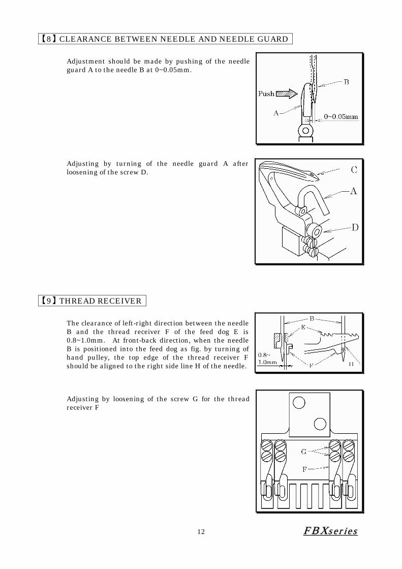
【8】CLEARANCE BETWEEN NEEDLE AND NEEDLE GUARD
Adjustment should be made by pushing of the needle guard A to the needle B at 0~0.05mm.
Adjusting by turning of the needle guard A after loosening of the screw D.
【9】THREAD RECEIVER
The clearance of left-right direction between the needle B and the thread receiver F of the feed dog E is 0.8~1.0mm. At front-back direction, when the needle B is positioned into the feed dog as fig. by turning of hand pulley, the top edge of the thread receiver F should be aligned to the right side line H of the needle.
Adjusting by loosening of the screw G for the thread receiver F

13 FFBBXXsseerr iieess
【10】FEED DOG AND STITCH LENGTH 10-1 Left-Right position of feed dog
Make sure each needles A drops into the center of the needle drop hole B of the feed dog J. Adjusting at left and right by loosening of the screw D (2 pieces) of the feed rocker C. At the same time, adjusting by loosening of the screw H (3 pieces) of the needle plate E, in order to be equal between each clearance G and also to be parallel between the feed dog and the feed grooves of the needle plate E.
10-2 Front-Back position of feed dog When the feed dog is positioned at both the front dead point and the back dead point by turning of hand pulley, each clearance F at the front and the back between the feed dog and the feed grooves of the Needle plate E is to be equal. Adjusting at front and back by loosening of the screw D (2 pieces) of the feed rocker C.
10-3 Height of feed dog When the feed dog is at the upper dead point, the feed dog J is to be parallel with the top surface of the needle plate E. Its height is 1.0~1.2mm. Adjusting by loosening of nut M and adjusting screw L of the feed dog J and also the screw K. After adjusting by up and down of the feed dog J, fasten the screw K. Then, fix the adjusting screw L up by the nut M after slight-touching it to the feed rocker. Tilt adjustment is to be done by loosening of the screw R of the feed up-down lever P after removing of the screw N.

14 FFBBXXsseerr iieess
10-4 Stitch length The stitch length can be adjusted from 2.1 up to 6.4mm without step. The following table shows the stitch length with the number of stitches within 1” (25.4mm) and 30mm.
No. of stitches Pulley position stitch length
(mm) within 1” within 30mm 2 2.1 12 14 3 3.0 8.5 10 4 4.0 6.2 7.5 5 5.0 5.0 6.0 6 6.0 4.2 5.0 L 6.4 4.0 4.5
■ How to change the stitch length (Fig. : Refer to previous page.)
1. Press push button S lightly with the left hand until the end of push button S touches an inside part.
2. With pressing push button S lightly, turn the hand pulley T by the right hand, until the push button S goes further into the depth.
3. Press the push button S strongly again. With keeping of this press, turn the hand pulley T in order to meet the number of pulley position to the mark U which can be selected as required.
4. After selecting of the desired stitch length, release the left hand. 5. The machine is adjusted the number 3 of pulley position.
In case of happening the defect after big-changing of the stitch length, adjust again for [6] timing of the looper to the needle, [7] timing of the retainer looper and the looper.
< Note> Before adjusting machine, be sure to turn off the motor.

15 FFBBXXsseerr iieess
【11】NEEDLE FEED 11-1 Front-Back position of needle
With reference to 10-4. Adjusting of stitch length, align the number L of pulley position to the mark B. Then, the stitch length is maximum.
When the needle C is going down from the top dead point by turning of hand pulley A, align the top end of needle hole of the needle C to the top surface of the feed dog D. The clearance between the needle and the needle drop hole of the feed dog D should be approx. 0.8mm as fig.
Remove the rubber plug E of the machine. Adjust the needle clamp with the moving to front and back after loosening of the screw F of the needle swing lever arm G.
11-2 Amount of needle feed movement The center mark N of the needle swing lever K should be aligned to the mark R of the needle swing lever pin M as fig. It is a standard setting. With this setting, the movement amount of the needle is synchronized with the movement amount of the feed. When adjusting of the movement amount of the needle, remove the cover H and the gasket J at the back side of the bed. Adjust by moving up and down of the needle swing lever pin M after loosening of the nut L. The needle feeding amount is increased when moving up. The needle feeding amount is decreased when moving down.
< Note> Before adjusting machine, be sure to turn off the motor.

16 FFBBXXsseerr iieess
【12】PRESSER FOOT 12-1 Pressure of presser foot
The presser foot pressure should be as light as possible, yet be sufficient to feed the fabric and produce uniform stitches. To increase the presser foot pressure, turn the adjusting knob clockwise.
12-2 Position of presser foot Fit the presser foot onto the presser bar so that the needle can drop correctly to the center of the needle drop hole on the presser foot. Adjustment is made by loosening screw B.
12-3 Foot lift Position stopper C with the presser foot approximately 9mm above the top surface of the needle plate and then tighten nut D.
< Note> Before adjusting machine, be sure to turn off the motor.

17 FFBBXXsseerr iieess
【13】REAR PULLER 13-1 Height of rear puller
Adjust the height of first puller D (left) and F (right) to make the gap 0.2~0.5mm to the surface of needle plate. Also make the gap 2.2~2.5mm between second puller E and lower puller as left below drawing shows. The above settings are adjusted by bolts A, B and C on the below drawings.
13-2 Puller pressure Pressure of pullers should be lowest so far as it feeds fabric smoothly. Adjust pressure of regulator at between 1.0kg/cm and 1.5kg/cm.

18 FFBBXXsseerr iieess
13-3 Feeding amount of rear puller Refer to 19. Programming
13-4 Tension of puller chain
Push the middle of chains by finger to bend 7mm by loosening gear A. This adjustment is applicable to all the chains on pullers A, B and C. It may cause motor to rotate unevenly if the chains are tense, bending amount is less than 7mm.
【14】STITCH FORMATION
14-1 Thread tension adjustment Thread tension varies according to sewing conditions such as the fabric, thread and stitch length to be used. Tension on the needle thread can be adjusted with nuts A. Tension on the looper thread can be adjusted with nuts B. To increase the tension, turn the nuts clockwise.
< Note > The tension should be as light as possible, yet be sufficient to produce uniform stitches.

19 FFBBXXsseerr iieess
14-2 Position of needle thread eyelet The position of the needle thread eyelet C should be adjusted about approx. 11.5mm from the center of the screw D.
14-3 Position of looper thread take-up eyelet 1. The looper thread eyelet F is to be fastened by
the screw G at the center of its long-hole. 2. The looper take-up bar E is to be fastened by
the screw H at the center passing position of the looper thread eyelet F.
< Note > To loose the needle thread, adjust the needle thread eyelet C to UP. To tight the needle thread, adjust the needle thread eyelet C to DOWN. Depending upon the kind of THREAD or FABRIC.
< Note > To loose the looper thread, move to the direction J for both of the looper thread eyelet F and the looper take-up bar E. To tight the looper thread, move to the direction K for both of the looper thread eyelet F and the looper take-up bar E.

20 FFBBXXsseerr iieess
14-4 Silicon Tank ■ The silicon oil prevents the thread-breakage, the
skip stitching and the heating of the needle top when using the synthetic and fiber material for the thread and the fabric. Use the silicon oil.
【15】CLEANING MACHINE
At the end of everyday, remove the presser foot and the needle plate and then clean the slots of the needle plate and the area around the feed dogs.
< Note > Remove the felt O when no-using of the silicon tank M. Check the volume of the silicon oil regularly after opening of the cap N. If shortage, supply the silicon oil properly.

21 FFBBXXsseerr iieess
【16】WAISTBAND CUTTER 16-1 Position and pressure ■Adjusting position
Adjust cutting edge of upper knife A to 2mm lower than surface of stationary knife B. The setting is adjusted by rotating cylinder shaft after loosening nut C.
■Adjusting pressure
Adjust the distance 28mm from the face of upper Cutter bracket D to the surface of adjusting screw G as right drawing shows. Check the pressure if 6 layers of denim fabrics can be securely cut. If not, increase the pressure by adjusting screw E.
16-2 Speed Refer to 19. Programming
16-3 Replacing cutter
To replace upper cutter I by detaching upper cutter bracket H and four screws for fixing plate. Stationary knife can be replaced by removing it from needle plate bracket J.
< Note > Be sure pressure of regulator should be less than 5kg/cm.

22 FFBBXXsseerr iieess
【17】DIRECT MOTOR 17-1 Direct Motor
Firstly take out the cap B and loosen screws C. Direct motor can be removed by loosening four screws A.
17-2 Gear Box Gear box can be easily removed by detaching five screws as right drawing shows.
17-3 Universal Joint Match arrow markings on both shafts to attach.

23 FFBBXXsseerr iieess
【18】SWITCH BOX 18-1 Switch Box ■Operation of switch
Switch box is located on the top cover of machine.
■Automatic Operation Switch (Red) 1. Switch box is operated after turning on
power. 2. Push red switch on left side and hold it at
one second. Light will be turned on, which means the machine is on automatic mode. Sensors, auto skip stitch and waistband cutter are automatically operated.
3. Push read switch and hold it at one second again to stop automatic mode.
■Spreader Switch (Yellow) 1. Manual mode or automatic mode, push
this button to adjust spreader whenever you need. Spreader is located on skip position while yellow light is on. The machine will not work while the light is on, nor waistband cutter works even if pedal is stepped on.
2. Push yellow switch to release.
■Manual cutter switch (Blue) Waistband cutter can be manually operated by pushing blue switch on right side when the machine is not running.
< Note > Take great care when cutter is operated. Be careful not to touch the cutter during operation.

24 FFBBXXsseerr iieess
【19】PROGRAMMING 19-1 Parameter of each parts
Cutting distance of waistband knife, lengths of skip stitch, etc. can be changed by the settings of each parameters.

25 FFBBXXsseerr iieess
19-2 Setting of parameter ■Preparation
Firstly make sure that power supply is securely switched off. Turn on power with keeping pressing “S” button on control box. Then the display shows as below.
When power is turned off
When power is turned on When power is turned on with “S” button
< Note > Do not change the setting of parameter 047.MAC. The machine may not work properly.

26 FFBBXXsseerr iieess
■EXAMPLE --- change the setting of stitch length by puller
1
2
3
Firstly turn on power with pressing “S” button Press and hold the key
until display shows 207 Display shows 207 (207.STL)
4
5
6
Press “S” button. Date will appear on display
3.5 on display means that stitch length is 3.5mm Change parameter into 4.6
by “C” and “D” button
7
8
Press “S” button to save the setting Back to sewing operation
mode

27 FFBBXXsseerr iieess
19-3 Parameter List
Parameter Detail Unit Max Min Default
179.PUA Needle stop position after heeling back
183.PUB Needle stop position during sewing stop
181.PDA Timing of starting puller
207.STL Puller stitch length mm 5.5 0.5 3.5
214.DS2 Final Cut Exceeded length of waistband at the end of operation This function is controlled by the sensor located under side protection cover beside presser foot
Cm 18.0 0.0 2.0
216.DS6 Timing of second puller activation from Initial Cut Second puller is on top position after Initial Cut. This function is adjusted to prevent fabric to get stuck on the puller, and prevent second puller to hook the beginning side of waistband tape accidentally.
Cm 18.0 0.0 10.0
215.DS4 Initial Skip Stitch Length of skip stitch on the beginning side of waistband.This function is controlled by the sensor on the folder.
<Caution> For constant length of skip stitch, it is very important that operators always start sewing from same point under presser foot.
Cm 18.0 0.0 2.0
217.D11 Initial Cut Exceeded length of waistband at the beginning of operation.
<Caution> Sewing speed is limited until initial cut ends. Maximum sewing speed can be applied only after initial cut.
Cm 5.0 0.0 2.0
219.D13 Final Skip Stitch Length of skip stitch at the finishing side of waistband. This function is controlled by the sensor on the folder.
Cm 4.0 0.0 2.0
222.PUM Position Control of back (second) puller Control position of puller depending on sewing condition.
1. Back puller moves up and down automatically. 2. Back puller is always on bottom position.
2 1 1
187.WS Sewing speed from Final Cut to Initial Cut Rpm 4800 400 1200
97.TK3 Operating time of waistband cutter ms 990 10 50~40
201.FNK Needle cooling function 0:Needle cooler starts when the pedal in ON. 1:Needle cooler starts depending on sewing speed
(parameter 199.nnk) 2:Under edge trimmer
2 0 0

28 FFBBXXsseerr iieess
【20】SENSITIVITY OF BEAM SENSOR
Make sure that green light is ON when the power is ON. Also check if orange light is ON when fabric is set. If not, adjust sensitivity of beam sensor by turning the dial counter clockwise as the right drawing shows.

29 FFBBXXsseerr iieess
【21】LAYOUT OF AIR PIPES