instruction sheet fb 300, fb 600, fb 900 filefb 900 up to 900 gallons 9 lbs. 642 ft2 multiple units...
TRANSCRIPT

LIFEGARD FLUIDIZED BED FILTERINSTRUCTION SHEET FB 300, FB 600, FB 900
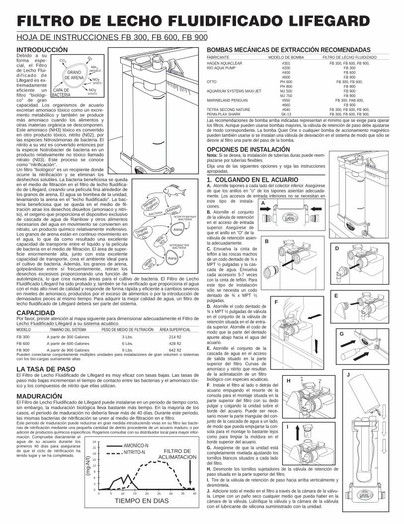
INTRODUCTIONDue to itsu n i q u eshape, theL i f e g a r dF l u i d i z e dBed filter isan extremelyefficient highc a p a c i t y“biological”filter. Aquaticorganisms excrete toxic ammonia as a meta-bolic waste product with additional ammoniaproduced as food and other organic matterbreaks down and decomposes. This toxicammonia (NH3) is converted to another toxiccompound nitrite (N02) by the Nitrosomonasspecies of bacteria. The nitrite is then convertedto a relatively non toxic compound, call nitrate(N03) by the Nitrobacter species of bacteria.This process is known as “nitrification”. A “biological” filter is a vessel where nitrificationoccurs and soluable waste is removed.Beneficial bacteria attach to the media withinthe Lifegard Fluidized Bed Filter creating a thin filmaround the sand grains. Water is pumped up throughthe unit lifting the sand into a “fluidized bed”. The ben-eficial bacteria attach to the media draw in dissolvedwastes (ammonia and nitrite) oxygen, supplied byRainbow’s exclusive water fall device and otherrequired nutrients from the passing water convertingthem to relatively harmless nitrate. The sand grains arein continual free fall through the water resulting in anexcellent transfer capability between the liquid and thebacterial film on the media. The enormously high surface are combined with this excellent transfer capability creates the perfect habitat for bacterialgrowth. In addition, the sand grains bump into eachother frequently knocking off excess debris and providinga self-cleaning function which allows new areas forbacterial growth. The Lifegard Fluidized Bed Filter hasbeen tested and proven to supply the highest level ofeffluent water quality and will respond quickly and efficiently to severe changes in ammonialevels caused by over feeding or the addition of too many fish at one time. To obtain highest water quality, a Lifegard Fluidized Bed Filter should be part of the system.
CAPACITYPlease refer to the following chart to properly size your Lifegard Fluidized Bed Filter to youraquatic system.
MODEL SYSTEM SIZE MEDIA WEIGHT SURFACE AREA
FB 300 Up to 300 Gallons 3 Lbs. 214 ft2
FB 600 Up to 500 Gallons 6 Lbs. 428 ft2
FB 900 Up to 900 Gallons 9 Lbs. 642 ft2
Multiple units can be connected together for larger volume installations or systems with extremely high bio-loads.
FLOW RATEThe Lifegard Fluidized Bed Filter is most effective at low rates. Lower flow rates increasethe contact time between the bacteria and the toxic ammonia and nitrite compounds thatthey utilize.
MATURATIONThe Lifegard Fluidized Bed Filter can be installed in a short period of time, however, thebiological maturation takes considerably longer. In most cases, the maturation period should take no longer than 40 days. during this period the nitrifying bacteria willattach themselves to the media within the filter.This maturation period can be greatly reduced by introducing live nitrifying bacteria intoyour filter, inoculating your filter with a small amount of detritus from a mature aquarium,or by the addition of specific chemicals. Please consult your local dealer for details.Test your aquarium waterdaily during the first 40 daysto insure the nitrificationcycle has occurred and iscompleted.
Recommended POWER HEAD PUMPMANUFACTURER PUMP MODEL FLUIDIZED BED FILTERHAGEN AQUACLEAR #301 FB 300, FB 600, FB 900RIO AQUA PUMP #200 FB 300
#400 FB 600#600 FB 900
OTTO PH 600 FB 300, FB 600PH 800 FB 900
AQUARIUM SYSTEMS MAXI-JET MJ 500 FB 300, FB 600MJ 750 FB 900
MARINELAND PENGUIN #550 FB 300, FB 600#660 FB 600
TETRA SECOND NATURE #640 FB 300, FB 600, FB 900PENN-PLAX SHARK SK-13 FB 300, FB 600, FB 900The above pump recommendations are the minimum that is required to operate the filters.Larger pumps can be used, however, the flow control valve must be adjusted accordingly. The QuietOne Pump or any magnetic drive pump can also be used if a by-pass valve is plumbed into the sys-tem so only a portion of the pump flow is diverted to the filter.
INSTALLATION OPTIONSNote: Hard plumbing may be substituted forflexible tubing if desired.Please choose one of the following options and follow theappropriate instructions.
1. HANGING ON THE AQUARIUMA. Screw in plugs oneach side of bottommanifold. Make sureplug “O” rings are seat-ed properly. The bot-tom inlet ports will notbe needed in this typeof installations.
B. Screw in check valveassembly in top inletport. Make sure checkvalve “O” rings is seatedproperly.
C. Wrap teflon tape onthe male threads of one¾" MPT x ½" barb elbowand the waterfall assem-bly. Wrap each fitting 5-7times with teflon tape. Onlyone ¾" MPT x ½" barb elbowwill be needed for this type ofinstallation.
D. Screw in the ¾" MPT x ½"barb elbow into the checkvalve assembly located onthe top inlet port. Screw inthe elbow so that the barbportion is pointing downtowards the aquarium water.
E. Screw in the water fallassembly into the outlet portlocated at the top of the filter.
F. Install the filter on the side or backof the aquarium by pushing themounting bracket spring assemblylocated at the top of the filter withyour thumb and hanging the unitover the edge of the aquarium. It maybe necessary to move the triangularportion of the water fall assembly toone side so that the mounting brack-et can be pushed far enough to clearthe molding on the top edge of theaquarium.
G. Make sure the unit is completelylevel by adjusting the white screwslocated on each side of the filter.
H. Remove the retainer screwsfrom the flow control valve located at the top outlet side of the fil-ter.
I. Pull the flow control valve straight up and remove.
J. Pour all the media into the filter through the valve chamber.Wipe off any media that may be in the valve chamber with a drycloth. Lubricate the valve and valve chamber with the sili-cone lubricant supplied with the unit.
SANDGRAIN
CO2O2
NH3AMMONIA
NO3NITRATE
NO2NITRITE
BACTERIALAYER
–
–
SAND
SAND
ORGANIC
NITROGEN
DISSOLVED
OXYGEN
O
AMMONIA
NH 3
NITRIT
ENO 2
NITRATE
NO 3
BACTERIA
NITROSOMONASBACTERIA
NITROBACTERBACTERIA
2
–
–
24
21
18
15
12
9
6
3
00 5 10 15 20 25 30 35 40
AMMONIA-NNITRITE-N FILTER
ACCLIMATION
TIME IN DAYS
(mg-
N/I)
The ammomia and nitrite curves that result from acclimation of a biological filter with aquatic species.
LIFEGARD®FLUIDIZEDBED FILTER
RAINBOW
LIFEGARD®
FLUIDIZEDBED FILTER
RAINBOW
LIFEGARD®FLUIDIZEDBED FILTER
RAINBOW
LIFEGARD®
FLUIDIZEDBED FILTER
RAINBOW
LIFEGARD®FLUIDIZBED
RAINBOW
A
BD
EF
G
H
I
J

K. Install the flow control valveback into the valve chambermaking sure the “O” ring isseated properly and all partsare free of any debris or media.
L. Screw in the two valveretainer screws.
M. Install the power headpump (not included with theunit) inside the aquarium in the desired location following the instructions of the pump manufacturer.
N. Attach one end of the ½" ID x 11/16" OD flexible tubing tothe outlet side of the power head pump.
O. Attach the other end of the flexible tubing to the ¾" MPTx ½" barb elbow located on the top inlet side of the filter. Inmost cases the flexible tubing will need to be cut to the proper length.
P. Adjust the flow control valve to the “off” position byturning the valve in a clockwise direction all the way untilit stops. Please note, as a safety feature, some water willalways pass through the flow control valve even in the“off” position.
Q. Plug in the pump and watch the filter fill with water.Quickly unplug the pump If you notice the entire bedof sand moving up the filter in one clump. Wait several minutes for the air to escape and the media tosettle to the bottom of the filter. Plug the pump back inand watch the filter fill with water and the remaining airpurge from the system.
R. Slowly adjust the flow control valve so that the mediais “Fluidized” up to the “maximum operating level” indicated on the clear chamber. Do notover adjust the valve so that the fluidization level is above this “maximum operat-ing level” or media may escape into the aquarium system. However, if this does occur,don’t worry if some media enters the aquarium. The media is completely inert and will notcause and harm to your aquatic animals or plants. The flow control valve is extremelyresponsive and sensitive to even a very slight change in position. Make very slightadjustments (1/16") and after each adjustment wait a few minutes for the level of thefluidized bed to change.
2. BESIDE THE AQUARIUM2A. Place filter on base in desired location next to theaquarium. Make sure unit is level on the base.
2B. Screw in plugs oneach side of the bot-tom manifold. Makesure plug “O” rings areseated properly. Thebottom inlet ports willnot be needed in thistype of installation.
2C. Screw in check valve assembly in top inlet port. Makesure check valve “O” ring is seated properly.
2D. Wrap teflon tape on the male threads of the two ¾"MPT x ½" barb elbow fittings provided. Wrap each fitting5-7 times with teflon tape.
2E. Screw one ¾" MPT x ½" barb elbow fitting into thecheck valve assembly located at the top inlet port. Screwin the elbow so that the barb portion is pointing straight upvertically. Screw in the other elbow fitting into the outlet port located at the top of the unit and align thebarb portion straight up vertically.
2F. Remove the retainer screws from the flow controlvalve located at the top outlet side of the filter. In steps2F through 2J, refer to installation drawings in section#1 (Hanging On The Aquarium).
2G. Pull the flow control valve straight up and remove.
2H. Pour in all the media into the filter through thevalve chamber. Wipe off any media that may be in thevalve chamber with a dry cloth. Lubricate the valve andvalve chamber with silicone lubricant supplied with the unit.
2I. Install the flow control valve back into the valve chambermaking sure the “O” ring is seated properly and all parts arefree of any debris or media.
2J. Screw in the two valve retainer screws.
2K. Install the power head pump (not included with unit)inside the aquarium in the desired location following theinstructions of the pump manufacturer.
2L. Attach one end of the ½" ID x 11/16" OD flexible tubing onthe outlet side of the power head pump.
2M. Attach the other end of the flexible tubing to the ¾" MPT x ½" barb elbow located at the top inlet side of thefilter. Cut the tubing to the proper length. Attach a hoseclamp and tighten accordingly.
2N. Attach the rest of the tubing to the ¾" MPT x ½" barb elbow located at the top outletside of the filter. Attach a hose clamp and tighten accordingly.
2O. Place the other end of the flexible tubing up and over the side or back of the aquari-um so that the water returns to theaquarium and agitates the surfaceto aerate the system. In some casesit may be desirable to connect theflexible tubing to a rigid plastic “U” or“J” tube (not supplied in this unit)that hangs on the aquarium. Attacha hose clamp to the rigid tube andtighten accordingly.
2P. Carefully follow steps P, Q, and Rin section #1 (Hanging On TheAquarium).
3. HANGING ON THEWET/DRY FILTER3A. Carefully follow all steps in sec-tion #1 (Hanging On The Aquarium).
4. UNDERNEATH AQUARIUM WITH A LIFEGARD SYSTEM4A. Place filter onbase in desiredlocation next tothe Lifegard mod-ular system. Theunit should bepositioned so thatit is the final stagein the system.
4B. Unplug pumpand completelydrain Lifegard sys-tem and plumbing.
4C. Screw thecheck valve as-sembly into theinlet port on theright side of thebottom manifold.Make sure the “O”ring is properlyseated.
4D. Screw in one plug on the leftside of the bottom manifold. Makesure the “O” ring is properly seated.
4E. Plumb a by-pass valve and “tee”after the LIfegard system which willdivert only a portion of the water fromthe Lifegard system and into the inletport on the right side of the bottommanifold. This may be accomplishedwith either rigid PVC plumbing orwith flexible vinyl tubing.
4F. Screw the otherplug into the top inletport on the left side ofthe unit. Make sure theplug “O” ring is seatedproperly. This inlet portwill not be used in thistype of installation.
4G. Wrap teflon tape onthe male threads of one¾" MPT x ½" barbelbow. Wrap the fitting 5-7 times with teflon tape.
4H. Screw the ¾" MPTx ½" barb elbow fittinginto the outlet side at thetop right side of the filter.Position the barb portion of the elbow straight up vertically.
4I. Follow steps 2N. and 2O. in section #2 (Beside The Aquarium).
LIFEGARD®
FLUIDIZEDBED FILTER
RAINBOW
LIFEGARD®FLUIDIZEDBED FILTER
RAINBOW
M&N
O
LIFEGARD®FLUIDIZEDBED FILTER
RAINBOW
AQUARIUM
LIFEGARD MODULAR SYSTEM
LIFEGARD®
FLUIDIZEDBED FILTER
RAINBOW
LIFEGARD®
FLUIDIZEDBED FILTER
RAINBOW
To Aquarium
By-Pass Valve "Tee"
L
M, N& O
P
2A
2C
2E
3A
4A
4C/4D
4E
4F
4H
K
2B

4J. Add media to the unit by following steps H, I, J, K, and L in section #1 (Hanging OnThe Aquarium).
4K. Open the by-pass valve completely.
4L. Carefully adjust the fluidization level by following steps, P, Q, and R in section #1(Hanging On The Aquarium).
4M. Partially close the by-pass valve to divert more water into the filter only if proper flu-idization is not achieved.
5. UNDERNEATH AQUARIUM WITH A CANISTER FILTER5A. Place filter on base in desired location next tothe canister filter. Position the filter so that it can beplumbed on the outlet side of the canister filter.
5B. Screw in the plugs on each side of the bottommanifold. Make sure the plug “O” rings are seatedproperly. In most cases, the bottom inlet ports will notbe needed in this type of installation. In steps 5Bthrough 5#, refer to installation drawings in section#2 (Beside The Aquarium).
5C. Screw in the check valve assembly in top inlet port.Make sure check valve “O” ring is seated properly.
5D. Wrap teflon tape on the male threads of the two¾" MPT x ½" barb elbow fittings provided. Wrap eachfitting 5-7 times with teflon tape.
5E. Screw one ¾" MPT x ½" barb elbow fitting intothe check valve assembly located at the top inlet port. Screw in the other elbow fitting intothe outlet port located at the top of the unit.
5F. Turn off the valve on the outlet side of the canister filter and completely drain the flex-ible tubing on the outlet side of the canister filter. In most cases, it will be necessary toremove the “U” or “J” tube form the back of the aquarium. Cut the flexible tubing on theoutlet side of the canister filter and plumb in line a by-pass valve and “tee” which will divertonly a portion of the water from the canister filter and into the inlet port on the left side ofthe top manifold. Attach hose clamp and tighten accordingly.
5G. Attach one end of the ½" ID x 11/16" OD flexible tubing to the ¾" MPT x ½" barb elbowlocated at the top outlet side of the filter. Attach hose clamp and tighten accordingly.
5H. Place the other end of the tubing up and over the side or back of the aquarium so thatthe water returns to the aquarium and agitates the surface to aerate the system. In comecases, flexible tubing can be attached to a rigid plastic “U” or “J” tube (not supplied in this unit)that hangs on the aquarium. Attach hose clamp to the rigid tube and tighten accordingly.
5I. Add media to the unit by following steps H, I, J, K. and L in section #1 (Hanging OnThe Aquarium).
5J. Open the by-pass valve completely.
5K. Carefully adjust the fluidization level by following steps, P, Q, and R in section #1(Hanging On The Aquarium).
5L. Partially close the by-pass valve to direct more water into the filter only if proper flu-idization is not achieved.
6. CONNECTING MULTIPLE UNITS TOGETHER6A. Place each filter on a base in desired location next to the aquarium system. Makesure unit is level on base. If it’s more desirable tohang the filters on the side or back of an aquariumor reservoir tank, please refer to steps E, F, and Gin section #1 (Hanging On The Aquarium).
6B. Screw plug into the top inlet port on each filter.Screw another plug into the bottom inlet port on theright side of the last filter in line and the left side ofthe first filter in line. Make sure the plug “O” ringsare seated properly.
6C. Screw check valve assembly into the inlet porton the right side of the bottom manifold of first filterand the left side of the next filter.
6D. Wrap teflon tape on the male threads of thetwo ¾" MPT x ½" barb elbow fittings. Wrap each fit-ting 5-7 times with teflon tape.
6E. Screw each of the ¾" MPT x ½" barb elbow fit-tings into the outlet ports on the top side of each fil-ter. Position the barb portion of the fitting straight up vertically.
6F. Attach one end of the ½" ID x 11/16" OD flexible tubing to the ¾" MPT x ½" barb elbowlocated at the top outlet side of the filter. Place the other end of the tubing up and over theside or back of the aquarium so that the water returns to the aquarium and agitates thesurface to aerate the system. In some cases, flexible tubing can be attached to a rigid plas-tic “U” or “J” tube (not supplied in this unit) that hangs on the aquarium. Repeat this foreach filter used. Attach hose clamps where needed and tighten accordingly.
6G. A by-pass valve may be needed depending on what size pump is used. The by-passvalve will divert only a portion of the water from the pump to the filters. Refer to step 4E insection #4 (Underneath Aquarium with a Lifegard System).
6H. Add media to each filter by following steps H, I, J, K, L, in section #1 (Hanging OnThe Aquarium).
6I. Open by-pass valve completely.
6J. Carefully adjust the fluidization level of each filter by following the steps P, Q and R insection #1 (Hanging On The Aquarium).
6K. Partially close the by-pass valve to divert more water into the filters only if proper flu-idization is not achieved.
ADDING REPLACEMENT MEDIA Hanging InstallationsA. Turn off pump and wait a full 10 minutes for the media to settle into the bottom cham-ber. If you have lost media, the level of the media will be below the “Media Fill Level” labellocated on the right side of the clear chamber.
B. Remove the retainer screws form the flow control valve located at the top outlet sideof the filter.
C. Pull the flow control valve straight up and remove.
D. Pour in the media up to the “Media Fill Level” label on the unit. Wipe off any media thatmay be in the valve chamber with a dry cloth. Lubricate the valve and valve chamber withthe Lifegard silicone lubricant supplied with the unit.
E. Install the flow control valve back into the valve chamber making sure the “O” ring isseated properly and all parts are free of any debris or media.
F. Screw in the two valve retainer screws.
Below Tank InstallationsA. Turn off pump to Lifegard Modular System or canister filter.
B. Completely drain flexible tubing on the outlet side of fluidized bed filter.
C. Follow steps A, B, C, D, E, and F in the above section (Adding Replacement Media,Hanging Installations).
ADDITIONAL EQUIPMENT REQUIREDAdditional equipment is needed in order to achieve optimal water quality in your aquari-um. This is vital to the health of your plants and animals as well as the nitrifying bacteriain your fluidized bed filter. Accumulation of large amounts of particulate and dissolvedorganic material will encourage the growth of other types of bacteria (heterotrophic) thatwill compete with the nitrifying bacterial for available space and nutrients. Additional equip-ment needed to reduce this accumulation of particulate and dissolved organic material willinclude the following.
A. MECHANICAL FILTRATIONThis type of filter will trap and remove floating debris and should be cleaned routinely. Aprefilter sponge should be attached to the power head pump to trap debris before it entersthe fluidized bed filter.
B. CHEMICAL FILTRATIONThis type of filter is usually filled with activated carbon that removes dissolved organic mol-ecules.
C. AERATIONAdditional aeration equipment is needed in order to maintain complete oxygen saturationin your aquarium system. This can be achieved with an air pump and diffuser as well asgood water movement at the surface of the aquarium. Proper circulation is necessary inorder to achieve oxygen saturation in your aquarium.
D. ULTRAVIOLET STERILIZATIONUltraviolet sterilizers control the transmission of disease from one fish to another by killingfree floating micro-organisms as they pass through the unit. The nitrifying bacteria are notkilled because they are attached to the media within the fluidized bed filter and are not freefloating. Ultraviolet sterilizers, although optional, should be the final stage of your filtrationsystem.
pH LEVELNitrifying bacteria produce acids when utilizing the ammonia and nitrite in the water.Theseacids decrease the pH in the aquarium and will inhibit the nitrification process when thisvalue drops below an acceptable level. This will led to a dangerous build up of ammonia!It is therefore vital that the pH be tested weekly and a proper level is maintained in theaquarium. Please contact the dealer in your are for advice in recommending the properadditive for maintaining the optimum pH level.
Recommended levels:
pH . . . . . . . . . . . . . . . fresh water . . . .above 6.2 . . . . . . . . . . . . . . . . . salt water . . . . . .8.2 - 8.4
WARRANTY: PENTAIR AQUATICS, warrants the original purchaser of this equipmentto be free from defects in workmanship or material for a period of one year from the dateof installation, provided this equipment is installed in accordance with factory instructionsand operated within the environment and limitations for which it was designed.
Should any of the integral parts of the unit become defective within one year from thedate of purchase, they will be repaired or replaced, if proven defective in workmanship ormaterial in the opinion of the manufacturer.
PENTAIR AQUATICS. will not be liable for any labor cost of removing or replacing com-ponent parts. This shall be the responsibility of the original purchaser, as will be the ship-ping charge to and from the plant.
Damage or failure of any part of a unit covered by this warranty, which results fromcauses directly, or indirectly connected with the installation, operation , environment, useor willful abuse, including without limitations, improper repackaging and damage incurredin shipping, is not covered by this warranty. Unless state law provides otherwise,anyimplied warranties which accompany the sale of these goods are limited to one year fromdate of installation.Unless state law provides otherwise, manufacturer will only be responsible for repair or
replacement of any of its products or parts thereof that are found to be defective, and willnot bear the cost of any incidental or consequential damages arising out of the occurrenceof such defect.
This warranty gives you specific rights and you may also have other rights which varyfrom state to state.
AQUARIUM
CANISTERFILTER
By-PassValve
IN
OUTPlug Plug
Plug
Plug
OUT
Check Valves
5A
6A
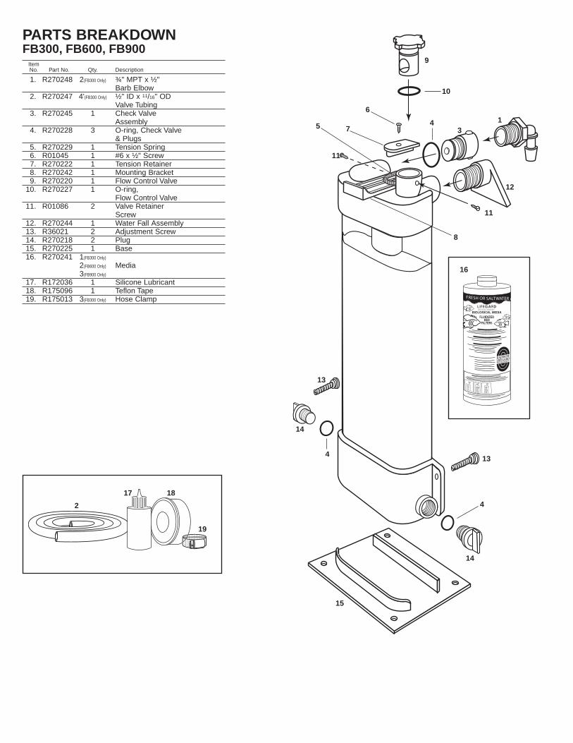
PARTS BREAKDOWNFB300, FB600, FB900
ItemNo. Part No. Qty. Description
1. R270248 2(FB300 Only) ¾" MPT x ½"Barb Elbow
2. R270247 4'(FB300 Only) ½" ID x 11/16" ODValve Tubing
3. R270245 1 Check ValveAssembly
4. R270228 3 O-ring, Check Valve & Plugs
5. R270229 1 Tension Spring6. R01045 1 #6 x ½" Screw7. R270222 1 Tension Retainer8. R270242 1 Mounting Bracket9. R270220 1 Flow Control Valve
10. R270227 1 O-ring,Flow Control Valve
11. R01086 2 Valve Retainer Screw
12. R270244 1 Water Fall Assembly13. R36021 2 Adjustment Screw14. R270218 2 Plug15. R270225 1 Base16. R270241 1(FB300 Only)
2(FB600 Only) Media3(FB900 Only)
17. R172036 1 Silicone Lubricant18. R175096 1 Teflon Tape19. R175013 3(FB300 Only) Hose Clamp FRESH OR SALTWATER AQUARIU
L I F E GA R D R EPLACEMENT
BIOLOGICAL MEDIAFLUIDIZED BED FILTERS
RAINBOWLIFEGARD
®
AQUARIUM PRODUCTS
9
10
6
7
8
16
17 18
19
1
2
34
4
4
5
11
11
12
13
13
14
14
15

MODE D'EMPLOI POUR FILTRE A LIT FLUIDE LIFEGARD®
INSTRUCTIONS POUR FB 300, FB 600, FB 900
INTRODUCTIONFélicitationspour l'achatde votre filtreà lit fluideL i f e g a r d ®.G r â c e à s a fo r m eunique, le fil-tre à lit fluideLifegard® estun filtre bio-logique de grande capacité, élaboré pourfournir une eau de la meilleure qualitébiologique par nitrification. Comme vous lesavez, les organismes aquatiques sécrè-tent de l'ammoniaque toxique contenuedans leurs rejets métaboliques, à laquelles'ajoute l'ammoniaque résultant de ladécomposition des excédents de nourri-ture et de matière organique. L'ammo-niaque (NH3) est convertie par les bactériesde type Nitrosomonas en un composéégalement toxique qui est le nitrite (NO2). Ason tour, le nitrite est converti en nitrate(NO3), composé relativement non toxique, par les bactéries de type Nitrobacter. Ce processus est appelé« nitrification ».
Le « lit fluide » est obtenu par la pression de l'eauqui, en traversant le filtre, met le sable en suspensionet crée un espace autour de chacun des grains. Cetespace permet aux bactéries mentionnées ci-dessusde se fixer à la surface de chaque grain pour créer unfilm bactérien. L'immense surface de contact (20 m2pour FB300), assurée par l'ensemble des grains desable en mouvement permanent dans l'eau, offre unecapacité maximale de transfert entre le film bactérienet l'eau. De surcroît, cet environnement est parfaite-ment adapté au développement des bactéries. Deplus, les nombreux chocs des grains de sable entreeux ont pour effet de chasser les débris excédentaireset de rendre ainsi le fluide autonettoyant au profit de lacroissance bactérienne.
CAPACITELe tableau ci-dessous vous permettra de choisir le modèle de filtre à lit fluide Lifegard®
adapté à votre installation :
MODELE VOLUME POIDS MEDIUM SURFACE
FB-300 Jusqu'à 1200 litres 1,3 kg 20 m2FB-600 Jusqu'à 2400 litres 2,7 kg 40 m2FB-900 Jusqu'à 3600 litres 4,0 kg 60 m2Pour les installations d'un volume supérieur ou ayant une charge biologique particulière-ment élevée, plusieurs filtres à lit fluide peuvent être installés ensemble (voir § 6).
DEBITLe filtre à lit fluide est conçu pour augmenter la surface de contact entre le film bactérienet les composants toxiques (ammoniaque et nitrite) qu'il transforme. Le débit d'eau qui tra-verse le filtre sera réglé à l'aide de la valve de réglage intégrée afin d'obtenir l'expansionmaximale de 100% du médium.
COLONISATIONLe filtre à lit fluide Lifegard® peut être installé très rapidement. La maturation biologiquenécessite par contre plus de temps. Dans la plupart des cas, elle se fait en moins de 40jours. Pendant ce temps, les bactéries nitrifiantes se fixent au médium à l'intérieur du fil-tre. Cette période de maturation peut être fortement réduite par l'introduction dans votrefiltre des bactéries nitrifiantes vivantes contenues dans CLEAR-FLO « super concentré »et « aquarium » ou en l'inoculant avec quelques résidus d'un aquarium mature. Veuillezconsulter votre détaillant pour une information plus complète.REMARQUE : Afin de préserver la vie bactérienne installée à l'intérieur de votre filtre à litfluide, il est conseillé de ne pas interrompre la fluidisation au-delà de quelques heures.
POMPES RECOMMANDEESFABRICANT MODELE DE POMPE FILTE A LIT FLUIDE
HAGEN AQUACLEAR #301 FB 300, FB 600, FB 900
RIO AQUA PUMP #200 FB 300
#400 FB 600
#600 FB 900
OTTO PH 600 FB 300, FB 600
PH 800 FB 900
AQUARIUM SYSTEMS MAXI-JET MJ 500 FB 300, FB 600
MJ 750 FB 900
MARINELAND PENGUIN #550 FB 300, FB 600
#660 FB 600
TETRA SECOND NATURE #640 FB 300, FB 600, FB 900
PENN-PLAX SHARK SK-13 FB 300, FB 600, FB 900
POSSIBILITES D'INSTALLATION
1. Accroché àl'aquariumA. Visser les bouchonssur chaque entrée ducollecteur inférieur envérifiant que les jointssoient positionnés cor-rectement. Les connec-teurs d'entrée inférieursne sont pas utilisés dansce type d'installation.B. Visser la valve anti-retour dans le connecteurd'entrée supérieure envérifiant que le joint soitplacé correctement.C. Enrouler 5 à 7 tours debande Téflon sur les file-tages du réducteur coudé (#1)et de l'assemblage chute-d’eau (#12). Un seul réducteurcoudé sera nécessaire pource type d'installation.D. Visser le réducteur coudé(#1) à l'intérieur de la valveanti-retour (#3) monté sur leconnecteur d'entrée supé-rieur. L'orienter vers la surfacede l'eau de l'aquarium.E. Visser l'assemblagechute-d'eau (#12) dans leconnecteur de sortie placéau sommet du filtre.F. Installer le filtre sur l'un descôtés de l'aquarium en pressantavec le pouce sur le levier placé ausommet du filtre (#8) puis en l'ac-crochant au rebord de l'aquarium.Il pourra être nécessaire de fairetourner légèrement l'assemblagechute-d'eau (#12) afin de permet-tre le passage de la pince de fixa-tion servant à accrocher le modulesur le rebord de l'aquarium.G. Vérifier que le module soit verti-cal en ajustant les vis blanches(#13) placées de chaque côté dufiltre.H. Oter les 2 vis de blocage de lavalve de débit placées sur la facesupérieure du filtre.I. Tirer la valve de débit (#9) vers le haut et l'enlever.J. Verser tout le médium (#16) à l'intérieur du filtre par le loge-ment de la valve.
SANDGRAIN
CO2O2
NH3AMMONIA
NO3NITRATE
NO2NITRITE
BACTERIALAYER
–
–
24
21
18
15
12
9
6
3
00 5 10 15 20 25 30 35 40
AMMONIA-NNITRITE-N FILTER
ACCLIMATION
TIME IN DAYS
(mg-
N/I)
The ammomia and nitrite curves that result from acclimation of a biological filter with aquatic species.
LIFEGARD®FLUIDIZEDBED FILTER
RAINBOW
LIFEGARD®
FLUIDIZEDBED FILTER
RAINBOW
LIFEGARD®FLUIDIZEDBED FILTER
RAINBOW
LIFEGARD®
FLUIDIZEDBED FILTER
RAINBOW
LIFEGARD®FLUIDIZBED
RAINBOW
A
BD
EF
G
H
I
J
TEMPS en joursCOURBES D’ACCLIMATATION D’UN FILTRE BIOLOGIQUE
AVEC DES ESPECES AQUATIQUES
FILTERACCLIMATE
AMMONIAQUE
NITRITE
QU
AN
TIT
E e
n m
g-N
/ I
GRAIN DESABLE
FILMBACTERIEN
AMMONIA QUE
SAND
SAND
ORGANIC
NITROGEN
DISSOLVED
OXYGEN
O
AMMONIA
NH 3
NITRIT
ENO 2
NITRATE
NO 3
BACTERIA
NITROSOMONASBACTERIA
NITROBACTERBACTERIA
2
–
–
SABLE
SABLEOXYGENE
DISSOUS O2
NITRATE
NO 3-
NITRATE
NO 2-
DECHETS
ORGANIQUES
AMMONIAQUE
NH 3
BACTERIESNITROSOMONAS
BACTERIESNITROBACTER
BACTERIES
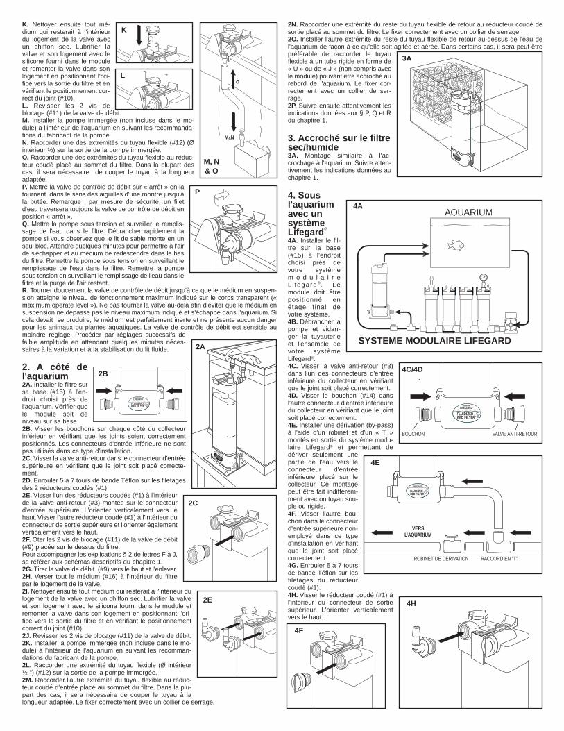
K. Nettoyer ensuite tout mé-dium qui resterait à l'intérieurdu logement de la valve avecun chiffon sec. Lubrifier lavalve et son logement avec lesilicone fourni dans le moduleet remonter la valve dans sonlogement en positionnant l'ori-fice vers la sortie du filtre et envérifiant le positionnement cor-rect du joint (#10).L. Revisser les 2 vis deblocage (#11) de la valve de débit.M. Installer la pompe immergée (non incluse dans le mo-dule) à l'intérieur de l'aquarium en suivant les recommanda-tions du fabricant de la pompe.N. Raccorder une des extrémités du tuyau flexible (#12) (Øintérieur ½) sur la sortie de la pompe immergée.O. Raccorder une des extrémités du tuyau flexible au réduc-teur coudé placé au sommet du filtre. Dans la plupart descas, il sera nécessaire de couper le tuyau à la longueuradaptée.P. Mettre la valve de contrôle de débit sur « arrêt » en latournant dans le sens des aiguilles d'une montre jusqu'àla butée. Remarque : par mesure de sécurité, un filetd'eau traversera toujours la valve de contrôle de débit enposition « arrêt ».Q. Mettre la pompe sous tension et surveiller le remplis-sage de l'eau dans le filtre. Débrancher rapidement lapompe si vous observez que le lit de sable monte en unseul bloc. Attendre quelques minutes pour permettre à l'airde s'échapper et au médium de redescendre dans le basdu filtre. Remettre la pompe sous tension en surveillant leremplissage de l'eau dans le filtre. Remettre la pompesous tension en surveillant le remplissage de l'eau dans lefiltre et la purge de l'air restant.R. Tourner doucement la valve de contrôle de débit jusqu'à ce que le médium en suspen-sion atteigne le niveau de fonctionnement maximum indiqué sur le corps transparent («maximum operate level »). Ne pas tourner la valve au-delà afin d'éviter que le médium ensuspension ne dépasse pas le niveau maximum indiqué et s'échappe dans l'aquarium. Sicela devait se produire, le médium est parfaitement inerte et ne présente aucun dangerpour les animaux ou plantes aquatiques. La valve de contrôle de débit est sensible aumoindre réglage. Procéder par réglages successifs defaible amplitude en attendant quelques minutes néces-saires à la variation et à la stabilisation du lit fluide.
2. A côté del'aquarium2A. Installer le filtre sursa base (#15) à l'en-droit choisi près del'aquarium. Vérifier quele module soit deniveau sur sa base.2B. Visser les bouchons sur chaque côté du collecteurinférieur en vérifiant que les joints soient correctementpositionnés. Les connecteurs d'entrée inférieure ne sontpas utilisés dans ce type d'installation.2C. Visser la valve anti-retour dans le connecteur d'entréesupérieure en vérifiant que le joint soit placé correcte-ment.2D. Enrouler 5 à 7 tours de bande Téflon sur les filetagesdes 2 réducteurs coudés (#1)2E. Visser l'un des réducteurs coudés (#1) à l'intérieurde la valve anti-retour (#3) montée sur le connecteurd'entrée supérieure. L'orienter verticalement vers lehaut. Visser l'autre réducteur coudé (#1) à l'intérieur duconnecteur de sortie supérieure et l'orienter égalementverticalement vers le haut.2F. Oter les 2 vis de blocage (#11) de la valve de débit(#9) placée sur le dessus du filtre.Pour accompagner les explications § 2 de lettres F à J,se référer aux schémas descriptifs du chapitre 1.2G. Tirer la valve de débit (#9) vers le haut et l'enlever.2H. Verser tout le médium (#16) à l'intérieur du filtrepar le logement de la valve.2I. Nettoyer ensuite tout médium qui resterait à l'intérieur dulogement de la valve avec un chiffon sec. Lubrifier la valveet son logement avec le silicone fourni dans le module etremonter la valve dans son logement en positionnant l'ori-fice vers la sortie du filtre et en vérifiant le positionnementcorrect du joint (#10).2J. Revisser les 2 vis de blocage (#11) de la valve de débit.2K. Installer la pompe immergée (non incluse dans le mo-dule) à l'intérieur de l'aquarium en suivant les recomman-dations du fabricant de la pompe.2L. Raccorder une extrémité du tuyau flexible (Ø intérieur ½ ") (#12) sur la sortie de la pompe immergée.2M. Raccorder l'autre extrémité du tuyau flexible au réduc-teur coudé d'entrée placé au sommet du filtre. Dans la plu-part des cas, il sera nécessaire de couper le tuyau à lalongueur adaptée. Le fixer correctement avec un collier de serrage.
2N. Raccorder une extrémité du reste du tuyau flexible de retour au réducteur coudé desortie placé au sommet du filtre. Le fixer correctement avec un collier de serrage.2O. Installer l'autre extrémité du reste du tuyau flexible de retour au-dessus de l'eau del'aquarium de façon à ce qu'elle soit agitée et aérée. Dans certains cas, il sera peut-êtrepréférable de raccorder le tuyauflexible à un tube rigide en forme de« U » ou de « J » (non compris avecle module) pouvant être accroché aurebord de l'aquarium. Le fixer cor-rectement avec un collier de ser-rage.2P. Suivre ensuite attentivement lesindications données aux § P, Q et Rdu chapitre 1.
3. Accroché sur le filtresec/humide3A. Montage similaire à l'ac-crochage à l'aquarium. Suivre atten-tivement les indications données auchapitre 1.
4. Sousl'aquariumavec unsystèmeLifegard®
4A. Installer le fil-tre sur la base(#15) à l'endroitchoisi près devotre systèmem o d u l a i r eL i fegard ®. Lemodule doit êtrepositionné enétage final devotre système.4B. Débrancher lapompe et vidan-ger la tuyauterieet l'ensemble devotre systèmeLifegard®.4C. Visser la valve anti-retour (#3)dans l'un des connecteurs d'entréeinférieure du collecteur en vérifiantque le joint soit placé correctement.4D. Visser le bouchon (#14) dansl'autre connecteur d'entrée inférieuredu collecteur en vérifiant que le jointsoit placé correctement.4E. Installer une dérivation (by-pass)à l'aide d'un robinet et d'un « T »montés en sortie du système modu-laire Lifegard® et permettant dedériver seulement unepartie de l'eau vers leconnecteur d'entréeinférieure placé sur lecollecteur. Ce montagepeut être fait indifférem-ment avec on toyau sou-ple ou rigide.4F. Visser l'autre bou-chon dans le connecteurd'entrée supérieure non-employé dans ce typed'installation en vérifiantque le joint soit placécorrectement.4G. Enrouler 5 à 7 toursde bande Téflon sur lesfiletages du réducteurcoudé (#1).4H. Visser le réducteur coudé (#1) àl'intérieur du connecteur de sortiesupérieur. L'orienter verticalementvers le haut.
LIFEGARD®
FLUIDIZEDBED FILTER
RAINBOW
LIFEGARD®FLUIDIZEDBED FILTER
RAINBOW
M&N
O
LIFEGARD®FLUIDIZEDBED FILTER
RAINBOW
AQUARIUM
LIFEGARD MODULAR SYSTEM
LIFEGARD®
FLUIDIZEDBED FILTER
RAINBOW
LIFEGARD®
FLUIDIZEDBED FILTER
RAINBOW
To Aquarium
By-Pass Valve "Tee"
L
M, N& O
P
2A
2C
2E
3A
4A
4C/4D
4E
4F
4H
K
SYSTEME MODULAIRE LIFEGARD
BOUCHON VALVE ANTI-RETOUR
ROBINET DE DERIVATION RACCORD EN “T”
VERSL’AQUARIUM
2B

4I. Suivre ensuite les indications données aux § N et O du chapitre 2.4J. Verser le médium dans l'unité en suivant attentivement les indications données aux §H, I, J, K et L du chapitre 1.4K. Ouvrir complètement le robinet de dérivation.4L. Régler précisément le niveau de fluidisation en suivant les indications données aux §P, Q et R du chapitre 1.4M. Si, après ouverture complète de la vanne de contrôle de débit (#9) te médium en sus-pension n'atteint pas le niveau de fonctionnement maximum indiqué sur le corps trans-parent (« maximum operating level »), fermer partiellement le robinet de dérivation pourdiriger plus d'eau vers le filtre.
5. Sous l'aquarium avec un filtreextérieur5A. Installer le filtre sur sa base (#15) à l'endroitchoisi près de votre filtre extérieur. Positionner lemodule afin de permettre le raccordement en sortiedu filtre extérieur.5B. Visser les bouchons sur chaque côté du col-lecteur inférieur en vérifiant que les joints soient cor-rectement positionnés. Dans la plupart des cas, lesconnecteurs d'entrées inférieurs ne sont pas utilisésdans ce type d'installation. Pour accompagner lesexplications des § B à E du chapitre 5, se référer auxschémas descriptifs du chapitre 2.5C. Visser la valve anti-retour (#3) dans le con-necteur d'entrée supérieure en vérifiant que le joint soit placé correctement.5D. Enrouler 5 à 7 tours de bande Téflon sur les filetages des 2 réducteurs coudés (#1).5E. Visser l'un des réducteurs coudés (#1) à l'intérieur de la valve anti-retour (#3) montéesur le connecteur d'entrée supérieur. Visser l'autre réducteur coudé (#1) à l'intérieur duconnecteur de sortie supérieur.5F. Débrancher la pompe de votre système.5G. Fermer le robinet à la sortie de votre filtre extérieur et vidanger entièrement le tuyau sou-ple branché en sortie. Dans la plupart des cas, il sera nécessaire d’ôter le tube rigide enforme de « U » ou de « J » du rebord de l’aquarium. Couper le tube flexible emboîté à la sor-tie du filtre extérieur et raccorder une dérivation (by-pass) à l’aide d’un robinet et d’un « T »permettant de dériver seulement une partie de l’eau sortant du filtre extérieur vers le con-necteur supérieur d’entrée. Fixer correctement le tube flexible à l’aide de collier de serrage.5H. Raccorder une extrémité du reste du tuyau flexible de retour au réducteur coudé desortie placé au sommet du filtre. Le fixer correctement avec un collier de serrage.5I. Installer l’autre extrémité du tuyau flexible de retour au-dessus de l’eau de l’aquariumde façon à ce qu’elle soit agitée et aérée. Dans certains cas, il pourra être préférable deraccorder le tuyau flexible à un tube rigide en forme de « U » ou de « J » (non comprisavec le module) pouvant être accroché au rebord de l’aquarium. Le fixer correctementavec un collier de serrage.5J. Verser le médium dans l’unité en suivant attentivement les indications données au §H, I, J, K et L du chapitre « 1. »5K. Ouvrir complètement le robinet de dérivation.5L. Régler précisément le niveau de fluidisation en suivant les indications données au §P, Q, et R du chapitre « 1. »5M. Si après ouverture complète de la vanne de contrôle de débit (#9) le médium en sus-pension n’atteint pas le niveau de fonctionnement maximum indiqué sur le corps trans-parent, fermer partiellement le robinet de dériva-tion pour diriger plus d’eau vers le filtre.
6. Raccordement de plusieursunités ensembles6A. Installer chaque filtre sur sa base (#15) à l’en-droit choisi près de votre système pour aquarium.Vérifier que le module soit de niveau sur sa base.Il est préférable d’accrocher les filtres sur l’un descotés de l’aquarium ou du réservoir, puis suivre lesindications données au § E, F, et G du chapitre « 1. »6B. Sur chacun des filtres, visser les bouchons(#14) dans les connecteurs d’entrée supérieurs etdans les connecteurs inférieurs non employés.Vérifier que les joints soient correctement position-nés.6C. Visser la valve anti-retour dans chacun desconnecteurs d’entrée inférieurs en vérifiant que le joint soit placé correctement.6D. Enrouler 5 à 7 tours de bande Téflon sur le filetage des réducleurs coudés (#1).6E. Visser chacun des réducteurs coudés (#1) à l’intérieur du connecteur de sortiesupérieure de chaque filtre. Les orienter verticalement vers le haut.6F. Raccorder une des extrémités du tuyau flexible au réducteur coudé de sortie placé ausommet du filtre. Installer l’autre extrémité du tuyau flexible de retour au dessus de l’aqua-rium de façon à ce que l’eau soit agitée et aérée. Dans certains cas, il sera peut êtrepréférable de raccorder le tuyau flexible à un tube rigide en forme de « U » ou de « J »(non compris avec le module) pouvant être accroché au rebord de l’aquarium. Répéter cesopérations pour chaque filtre employé. Fixer correctement les tuyaux à l’aide de colliersde serrage.6G. Un robinet de dérivation (« by-pass ») pourra être nécessaire suivant les caractéris-tiques de la pompe employée. Le robinet de dérivation dirige seulement une partie del’eau venant de la pompe vers les filtres. Se référer aux indications données au § 4E duchapitre « 4. »6H. Verser le médium dans l’unité en suivant attentivement les indications données au §H, I, J, K et L du chapitre « 1. »
6I. Ouvrir complètement le robinet de érivation.6J. Régler précisément le niveau de fluidisation en suivant les indications données au§ P,Q et R du chapitre « 1. »6K. Si après ouverture complète de la vanne de contrôde débit (#9) le médium en sus-pension n’atteint pas le niveau de fonctionnement maximum indiqué sur le corps trans-parent (« maximum operating level »), fermer partiellement le robinet de dérivation pouraugmenter le volume d’eau vers le filtre.
ENTRETIENLe filtre à lit fluide ne nécessite pas de maintenance, sauf en cas de fuite accidentelle demédium.
Ajout de médium sur filtre accroché.
A. Débrancher la pompe et attendre au moins 10 minutes pour que le médiumredescende au fond. Une partie du médium a été perdue si la hauteur de médium estinférieure au niveau indiqué « Media Fill » Level sur le côté droit de la chambre transpa-rente.B. Oter les 2 vis de blocage (#11) de la valve de débit placées sur le dessus du filtre.C. Tirer la valve de débit (#9) vers le haut et l’enlever.D. Verser tout le médium (#16) à l’intérieur du filtre par le logement de la valve.E. Nettoyer ensuite tout médium qui resterait à l’intérieur du logement de la valve avec unchiffon sec. Lubrifier la valve et son logement avec le silicone fournit dans le module et remonter la valve dans son logement en positionnant l’orifice vers la sortiedu filtre et en vérifiant le positionnement correct du joint (#10).F. Revisser les 2 vis de blocage (#11) de la valve de débit.Ajout de médium sur filtre installé sous l’aquariumA. Débrancher la pompe du système modulaire Lifegard ou du filtre extérieur.B. Vidanger complètement le tuyua flexible raccordé en sortie du filtre à lit fluide.C. Suivre les indications données au § A, B, C, D, E et F ci-dessus.
EQUIPEMENT SUPPLEMENTAIRE CONSEILLEUn équipement supplémentaire est conseillé afin d’obtenir une eau de qualité optimaledans votre aquarium. Ceci est important pour la santé de vos plantes et de vos animauxaquatiques autant que pour les bactéries nitrifiantes à l’intérieur de votre filtre à lit fluide.L’équipement nécessaire pour réduire l’accumulation de particules et de matièresorganiques dissoutes comprendra les matériels suivants :
A. FILTRATION MECANIQUECe type de filtre retiendra les débris en suspension et devra être nettoyé régulièrement.Une éponge pré-filtre devra être fixée à la pompe immergée afin d’empêcher les débrisde pénétrer à l’intérieur du filtre à lit fluide.
B. FILTRATION CHIMIQUECe type de filtre est habituellement rempli avec du charbon actif qui retient les moléculesorganiques dissoutes.
C. AERATIONUn dispositif d’aération est nécessaire afin de maintenir la saturation en oxygène de l’eaude votre aquarium. Ceci peut être obtenu à l’aide d’une pompe à air ou par l’agitation à lasurface de l’aquarium. Une circulation efficace de l’eau est nécessaire pour assurer la sa-turation en oxygène dans l’aquarium.
D. STERILISATION PAR ULTRAVIOLETSLe stérilisateur à ultraviolets évite la transmission des maladies d’un poisson à l’autre entuant les micro-organismes libres en suspension qui passent au travers. Parce qu’elles nesont pas en suspension dans l’eau mais accrochées au médium à l’intérieur du filtre à litfluide, les bactéries nitrifiantes ne sont pas tuées. Le stérilisateur à ultraviolets, bien qu’op-tionnel, doit être le module final de vôtre système de filtration.
GARANTIE—PENTAIR AQUATICS, garantit à l'acheteur initial que cet appareil estexempt de tout défaut de fabrication ou de malfaçon pendant un an à compter de la dated'achat , sous réserve que l'appareil ait été installé conformément aux instructions du fab-ricant et fonctionne dans les conditions et limites pour lesquelles il a été conçu. A causede nombreuses circonstances opérationnelles indépendantes de la volonté de RainbowLifegard, les lampes germicides à ultraviolets sont exclues de la garantie. En cas de défec-tion d'une pièce dans l'année qui suit la date d'achat, elle sera réparée ou remplacée si lefabricant constate un défaut de fabrication ou une malfaçon.
PENTAIR AQUATICS ne prend pas en charge les frais de transport et de main d'œuvrepour le remplacement des pièces de rechange. La garantie ne couvre pas les dommagesou défauts résultant directement ou indirectement de l'installation, du fonctionnement, del'environnement, de l'utilisation ou d'une mauvaise utilisation intentionnelle, y compris etsans réserve, mauvais ré-emballage et dommages durant le transport. Sauf spécificationcontraire prévue par la loi, toute garantie implicite accompagnant la vente de ces produitss'arrête au bout d'un an à compter de la date d'achat
AQUARIUM
CANISTERFILTER
By-PassValve
IN
OUTPlug Plug
Plug
Plug
OUT
Check Valves
5A
6A
FILTREEXTERIEUR
Valve deDérivation
Bouchon Bouchon
Bouc
hon
Bouc
hon
Valvesanti-relour
SORTIE SORTIE
ENTREE
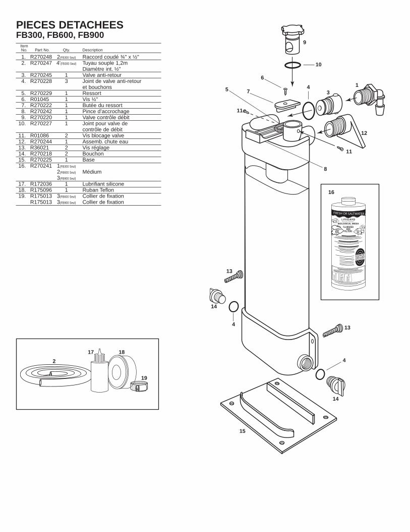
PIECES DETACHEESFB300, FB600, FB900
ItemNo. Part No. Qty. Description
1. R270248 2(FB300 Seul) Raccord coudé ¾" x ½"2. R270247 4'(FB300 Seul) Tuyau souple 1,2m
Diamètre int. ½" 3. R270245 1 Valve anti-retour4. R270228 3 Joint de valve anti-retour
et bouchons5. R270229 1 Ressort6. R01045 1 Vis ½"7. R270222 1 Butée du ressort8. R270242 1 Pince d’accrochage9. R270220 1 Valve contrôle débit
10. R270227 1 Joint pour valve de contrôle de débit
11. R01086 2 Vis blocage valve12. R270244 1 Assemb. chute eau13. R36021 2 Vis réglage14. R270218 2 Bouchon15. R270225 1 Base16. R270241 1(FB300 Seul)
2(FB600 Seul) Médium3(FB900 Seul)
17. R172036 1 Lubrifiant silicone 18. R175096 1 Ruban Teflon19. R175013 3(FB600 Seul) Collier de fixation
R175013 3(FB900 Seul) Collier de fixation
FRESH OR SALTWATER AQUARIU
L I F E GA R D R EPLACEMENT
BIOLOGICAL MEDIAFLUIDIZED BED FILTERS
RAINBOWLIFEGARD
®
AQUARIUM PRODUCTS
9
10
6
7
8
16
17 18
19
1
2
34
4
4
5
11
11
12
13
13
14
14
15

LIFEGARD® FLIESSBETTFILTERANLEITUNG FB 300, FB 600, FB 900
EINLEITUNGAufgrund ihrereinzigar tigenForm sind dieL i f e g a r d ®
Fliessbettfilteräusserst wirk-same "biolo-gische" Filtermit hoher Ka-pazität. Was-s e r o r g a n i s -men scheiden als Abfallprodukt desStoffwechsels schädliches Ammoniak aus,und beim Abbau und Zerfall von Nahrungfällt zusätzliches Ammoniak an. Eine Artvon Bakterien mit dem NamenNitrosomonas wandelt dieses schädlicheAmmoniak (NH3) in Nitrit (NH2) - eineandere schädliche Verbindung - um.Nitrobacter-Bakterien wandeln diese Nitritdaraufhin in eine relativ unschädlicheVerbindung um, nämlich Nitrat (NO3).Dieser Prozess ist gemeinhin unter demNamen "Nitrifikation" bekannt. Ein "biolo-gischer" Filter ist ein Gefäss, in dem Nitrifikation statt-findet und löslicher Abfall entfernt wird. NützlicheBakterien haften sich am Filtermedium im Lifegard®-Fliessbettfilter fest und erzeugen eine dünne Schichtauf den Sandkörnern. Wasser wird durch das Gerätgepumpt und erzeugt ein "fliessendes Sandbett". Dieauf den Sandkörnern haftenden nützlichen Bakterienziehen gelösten Abfall (Ammoniak und Nitrit) sowieSauerstoff, der von der exklusiven Rainbow-Wasserfalleinheit geliefert wird, und weitere erforder-liche Nährstoffe aus dem durchfliessenden Wasser her-aus und wandeln sie in relativ harmloses Nitrat um. DieSandkörner befinden sich im Wasser imSchwebezustand, was eine ausgezeichnete Übertra-gungsfähigkeit zwischen der Flüssigkeit und derBakterienschicht auf dem Filtermedium zur Folge hat.Die enorm grosse Oberfläche und diese ausgezeich-nete Übertragungsfähigkeit schaffen zusammen perfek-te Rahmenbedingungen für bakterielles Wachstum. Darüber hinaus kollidieren dieSandkörner miteinander und verlieren dabei überschüssigen Abfall - eine Art derSelbstreinigung, die weiteren Raum für bakterielles Wachstum schafft.Tests des Lifegard®-Fliessbettfilters haben gezeigt, dass er die höchste Qualität des abfliessenden Wasserssicherstellt und schnell und wirksam auf durchgreifende Veränderungen desAmmoniakgehaltes aufgrund einer Überfütterung oder auf eine übermässig hohe Anzahlvon Fischen reagiert. Wenn Sie an bestmöglicher Wasserqualität interessiert sind, dannsollte ein Lifegard®-Fliessbettfilter zu Ihrem System gehören.
KAPAZITÄTBeachten Sie zur richtigen Dimensionierung Ihres Lifegard®-Fliessbettfilters die folgendeTabelle.MODELL SYSTEMGRÖSSE MEDIUM-GEWICHT OBERFLÄCHEFB 300 Bis 300 Gallonen 3 lbs. 214 ft²FB 600 Bis 600 Gallonen 6 lbs. 428 ft²FB 900 Bis 900 Gallonen 9 lbs. 642 ft²Mehrere Geräte können für grössere Anlagen oder Systeme mit extrem hoher biologi-scher Belastung zusammengeschaltet werden.
DURCHFLUSSMENGEDer Lifegard®-Fliessbettfilter ist bei niedrigen Durchflussmengen am wirksamsten.Niedrige Durchflussmengen erhöhen die Berührungsdauer zwischen den Bakterien undden von Ihnen verarbeiteten Ammoniak- und Nitritverbindungen.
REIFUNGDer Lifegard®-Fliessbettfilter kann innert kürzester Frist installiert werden, die biologischeReifung braucht jedoch wesentlich mehr Zeit. In den meisten Fällen dürfte dieReifungsdauer nicht mehr als 40 Tage betragen. Während dieser Zeit setzen sich dieNitrifikationsbakterien am Medium im Filter fest.Diese Reifungsdauer kannwesentlich reduziert werden, wennSie lebende Nitrifikationsbakterien inIhren Filter einführen, Ihren Filter miteiner kleinen Menge Abfall auseinem reifen Aquarium impfen oderbestimmte Chemikalien beigeben.Für Einzelheiten wenden Sie sichbitte an Ihren örtlichen Händler.Prüfen Sie das Wasser IhresAquariums während der ersten 40Tage täglich, um sich zu vergewis-sern, dass der Nitrifikationszyklusstattgefunden hat und beendet ist.
Empfohlene POWERHEAD-PUMPENHERSTELLER PUMPENMODELL FLIESSBETTFILTERHAGEN AQUACLEAR Nr. 301 FB 300, FB 600, FB 900RIO AQUA PUMP ... ...
#400 FB 600#600 FB 900
OTTO PH 600 FB 300, FB 600PH 800 FB 900
AQUARIUM SYSTEMS MAXI-JET MJ 500 FB 300, FB 600MJ 750 FB 900
MARINELAND PENGUIN #550 FB 300, FB 600#660 FB 600
TETRA SECOND NATURE #640 FB 300, FB 600, FB 900PENN-PLAX SHARK SK-13 FB 300, FB 600, FB 900Die oben empfohlenen Pumpen sind das Minimum, das für den Betrieb der Filter erforderlich ist.Grössere Pumpen können verwendet werden, das Durchflussregelventil muss jedoch entsprechendeingestellt werden. Die Quiet One-Pumpe oder irgendeine Pumpe mit magnetischem Antrieb kann eben-falls verwendet werden, wenn ein Umgehungshahn in das Leitungssystem eingebaut wird, so dass nurein Teil der Durchflussmenge der Pumpe in den Filter gelangt.
INSTALLATIONSMÖGLICHKEITENAnmerkung: Wenn gewünscht, können anstelle von SchläuchenRöhre verwendet werden.Wählen Sie bitte eine der nachstehenden Installationsmöglichkeitenund beachten Sie die entsprechende Anleitung.
1. AM AQUARIUM HÄNGENDA. Am unteren Rohranschlussteil auf beiden Seiten Stöpsel ein-schrauben. Darauf acht-en, dass die Stöpsel-O-Ringe richtig sitzen. Beidieser Installationsartwerden die unterenEinlassöffnungen nichtgebraucht.
B. Absperrventileinheit indie obere Einlassöffnungschrauben. Darauf achten,dass die Absperrventil-O-Ringe richtig sitzen.
C. Teflonband auf dasAussengewinde eines ¾"MPT x ½" Winkel-Stecknippels und derWasserfaleinheit wickeln.Jedes Gewinde 5- bis 7-mal mit Teflonband umwickeln.Für diese Installationsart wirdnur ein ¾" MPT x ½" Winkel-Stecknippel gebraucht.
D. Den ¾" MPT x ½" Winkel-Stecknippel in die Absperrven-tileinheit an der oberen Einlas-söffnung schrauben. So hinein-schrauben, dass der Steck-nippel nach unten gegen dasAquariumwasser zeigt.
E. Wasserfalleinheit in dieAuslassöffnung oben am Filterschrauben.
F. Den Filter seitlich oder an derRückwand des Aquariums installieren,indem Sie mit dem Daumen auf diegefederte Montageklammer oben amFilter drücken und den Filter an denRand des Aquariums hängen. Even-tuell muss dos dreieckige Teil derWasserfalleinheit zur Seite gedrehtwerden, damit die Montageklammerweit genug nach vorn gestossen wer-den kann.
G. Mit den weissen Schrauben aufbeiden Seiten des Filter dafür sorgen,dass dieser senkrecht steht.
H. Beide Halteschrauben amDurchflussregelventil oben auf derAuslassseite des Filters entfernen.
I. Durchflussregelventil gerade nach oben ziehen und wegnehmen.
J. Gesamte Mediummenge durch die Ventilkammer in den Filtergiessen. Eventuelle Mediumrück-stände in der Ventilkammer mit einemtrockenen Tuch entfernen. Ventil und Ventilkammer mit dem mitgeliefer-ten Silikonschmiermittel schmieren.
SANDGRAIN
CO2O2
NH3AMMONIA
NO3NITRATE
NO2NITRITE
BACTERIALAYER
–
–
24
21
18
15
12
9
6
3
00 5 10 15 20 25 30 35 40
AMMONIA-NNITRITE-N FILTER
ACCLIMATION
TIME IN DAYS
(mg-
N/I)
The ammomia and nitrite curves that result from acclimation of a biological filter with aquatic species.
LIFEGARD®FLUIDIZEDBED FILTER
RAINBOW
LIFEGARD®
FLUIDIZEDBED FILTER
RAINBOW
LIFEGARD®FLUIDIZEDBED FILTER
RAINBOW
LIFEGARD®
FLUIDIZEDBED FILTER
RAINBOW
LIFEGARD®FLUIDIZBED
RAINBOW
A
BD
EF
G
H
I
J
AMMONIAK-NNITRIT-N
SAND-KORN
BAKTERIEN-SCHICHT
NO3-
NITRAT
NO3AMMONIAK
NO2-
NITRIT
FILTERAKKLIMATISIERUNG
ZEIT IN TAGENDer sich aus der Akklimatisierung des biologischen Filters mit Wasserorganismen eigenbenden Ammoniak und Nitrit-Kurven
SAND
SAND
ORGANIC
NITROGEN
DISSOLVED
OXYGEN
O
AMMONIA
NH 3
NITRIT
ENO 2
NITRATE
NO 3
BACTERIA
NITROSOMONASBACTERIA
NITROBACTERBACTERIA
2
–
–
NITRAT
NO 3_
Organischer
Stickstoff
Gelöster
Saurstoff
NITRIT
NO 2_
Ammoniak
NITROBACTERBAKTERIEN
NITROSOMONASBAKTERIEN
BAKTERIEN

K. Durchflussregelventil wieder indie Ventilkammer einsetzen unddabei darauf achten, dass der O-Ring richtig sitzt und dass alleTeile frei von Schmutz undMediumrück-ständen sind.L. Beide Ventilhalteschraubenhineinschrauben.M. Powerhead-Pumpe (nicht mit-geliefert) an der gewünschtenStelle im Aquarium installierenund dabei die Anleitung desPumpenherstellers beachten.N. Ein Ende des ½" Innen-Ø x 11/16" Aussen-Ø-Schlauches an dieAuslassseite der Powerhead-Pumpe anschliessen.O. Das andere Ende des Schlauches an den ¾" MPT x ½" Winkel-Stecknippel auf der oberen Einlassseite des Filters anschliessen. Inden meisten Fällen muss der Schlauch auf die richtige Längegeschnitten werden.P. Durchflussregelventil durch Drehen im Uhrzeigersinn biszum Anschlag ganz schliessen. Beachten Sie bitte, dass aus Sicherheitsgründen immer etwas Wasser durch dasDurchflussregelventil fliesst, auch wenn es ganz gesch-lossen ist.Q. Pumpe an die Steckdose anschliessen und zusehen, wiesich der Filter mit Wasser füllt. Pumpe sofort von der Steckdosetrennen, wenn Sie feststellen, dass sich das ganze Sandbett aneinem Stück im Filter nach oben bewegt. Einige Minutenwarten, damit die Luft entweichen und sich das Filtermediumam Boden des Filters absetzen kann. Pumpe wieder an dieSteckdose anschliessen und zusehen, wie sich der Filter mitWasser füllt und die restliche Luft aus dem System entferntwird.R. Durchflussregelventil sorgfältig so einstellen, dass das Filtermedium bis zum an der transparentenKammer mit "MAXIMUM OPERATING LEVEL" angegebenen maximalen Niveau "aufgewirbelt" wird.Das Ventil nicht so stark öffnen, dass sich das Niveau über dem Maximum befindet, da sonstFiltermedium in das Aquarium gelangen kann. Wenn dies trotzdem erfolgt, besteht kein Grund zurBesorgnis. Das Medium ist völlig neutral und schadet Ihrer Wasserfauna und -flora nicht. DasDurchflussregelventil reagiert äusserst empfindlich auf jede - auch noch so kleine - Änderung derStellung. Nur in sehr kleinen Schritten (1/16", 1,5 mm) ändern und nach jeder Änderung einige Minutenwarten, um zu sehen wie das Fliessbett reagiert.
2. NEBEN DEM AQUARIUM2A. Filter mit der Bodenplatte an der gewünschte Stelle in derNähe des Aquariums aufstellen. Darauf achten, dass der Filtersenkrecht steht.2B. Am unterenRohranschlussteil aufbeiden Seiten Stöpseleinschrauben. Daraufachten, dass die Stöpsel-O-Ringe richtig sitzen.Bei dieser Installationsartwerden die unteren Einlassöffnungen nicht gebraucht.2C. Absperrventileinheit in die obere Einlassöffnungschrauben. Darauf achten, dass die Absperrventil-O-Ringerichtig sitzen.2D. Teflonband auf das Aussengewinde beider ¾" MPT x ½"WinkelStecknippel wickeln. Jedes Gewinde 5- bis 7-mal mitTeflonband umwickeln.2E. Einen ¾" MPT x ½" Winkel-Stecknippel in dieAbsperrventileinheit an der oberen Einlassöffnung schrauben.Den WinkelStecknippel so hineinschrauben, dass er senkrechtnach oben zeigt. Den anderen WinkelStecknippel in dieAuslassöffnung oben am Filter schrauben und ebenfalls soausrichten, dass er senkrecht nach oben zeigt.2F. Beide Halteschrauben am Durchflussregelventil obenauf der Auslassseite des Filters entfernen. Für die Schritte2F bis 2J siehe die Abbildungen im Abschnitt 1 (AM AQUA-RIUM HÄNGEND).2G. Durchflussregelventil gerade nach oben ziehen undwegnehmen.2H. Gesamte Mediummenge durch die Ventilkammer in denFilter giessen. Eventuelle Mediumrückstände in der Ventilkammermit einem trockenen Tuch entfernen. Ventil und Ventilkammer mitdem mitgelieferten Silikonschmiermittel schmieren.2I. Durchflussregelventil wieder in die Ventilkammer einsetzenund dabei darauf achten, dass der O-Ring richtig sitzt und dassalle Teile frei von Schmutz und Mediumrückständen sind.2J. Beide Ventilhalteschrauben hineinschrauben.2K. Powerhead-Pumpe (nicht mitgeliefert) an der gewünschtenStelle im Aquarium installieren und dabei die Anleitung desPumpenherstellers beachten.2L. Ein Ende des j" Innen-Ø x 11/16" Aussen-Ø-Schlauches an dieAuslassseite der Powerhead-Pumpe anschliessen.2M. Das andere Ende des Schlauches an den ¾" MPT x ½" WinkelStecknippel auf der oberenEinlassseite des Filters anschliessen. Schlauch auf die richtige Länge schneiden. EineSchlauchschelle anbringen und entsprechend festziehen.
2N. Rest des Schlauches an den ¾" MPT x ½" WinkelStecknippel auf der oberen Auslassseite desFilters anschliessen. Eine Schlauchschelle anbringen und entsprechend festziehen.2O. Das andere Ende des Schlauches nach oben zum Aquarium führen, so dass das Wasser indas Aquarium zurückfliesst und dieOberfläche umrührt, um das System zubelüften. In bestimmten Fällen kann eswünschbar sein, den Schlauch an einstarres, U- oder J- förmigesKunststoffrohr (nicht mitgeliefer t)anzuschliessen, das an das Aquariumgehängt wird. Eine Schlauchschelleanbringen und entsprechend festziehen.2P. Schritte P, Q und R im Abschnitt 1(AM AQUARIUM HÄNGEND) genaubefolgen.
3. AM NASS-/TROCKEN-FILTER HÄNGEND3A. Alle Schritte im Abschnitt 1 (AMAQUARIUM HÄNGEND) genau befolgen.
4. UNTERHALB DES AQUARIUMS MIT LIFEGARD®-SYSTEM4A. Filter mit der Bodenplatte an der gewünschte Stelle in der Nähe des Lifegard® Modular-Systems aufstellen.Der Filter muss dieletzte Stufe diesesSystems bilden.4B. Pumpe von derSteckdose trennenund alles Wasseraus dem Lifegard®-
System und denR o h r l e i t u n g e nablassen.4C. Absperr ven-ti leinheit in dieEinlassöffnung aufder rechten Seitedes unteren Rohran-s c h l u s s t e i l sschrauben. Daraufachten, dass der O-Ring richtig sitzt.4D. Auf der linkenSeite des unteren Rohranschlussteilseinen Stöpsel einschrauben. Daraufachten, dass der O-Ring richtig sitzt.4E. Hinter dem Lifegard®-System einenUmgehungshahn und ein T-Stück in dieRohrleitungen einbauen, so dass nur einTeil des vom Lifegard®-System kom-menden Wasser zur Einlassöffnung aufder rechten Seite des unterenRohranschlussteils gelangt. Die kann mitstarren PVC-Röhren oder mit PVC-Schläuchen erfolgen.4F. Den anderen Stöpselin die obere Einlassöffnungauf der linken Seite desFilters schrauben. Daraufachten, dass der O-Ringrichtig sitzt. Bei dieserInstallationsart wird dieseEinlassöffnung nichtgebraucht.4G. Teflonband auf dasAussengewinde eines ¾"MPT x ½" Winkel-Stecknippels wickeln. DasGewinde 5- bis 7-mal mitTeflonband umwickeln.4H. Den ¾" MPT x ½"Winkel-Stecknippel in dieAuslassseite oben rechts am Filter schrauben. Den Stecknippel so ausrichten, dass er senkrecht nachoben zeigt.4I. Schritte 2N und 2O im Abschnitt 2(NEBEN DEM AQUARIUM) befolgen.
LIFEGARD®
FLUIDIZEDBED FILTER
RAINBOW
LIFEGARD®FLUIDIZEDBED FILTER
RAINBOW
M&N
O
LIFEGARD®FLUIDIZEDBED FILTER
RAINBOW
AQUARIUM
LIFEGARD MODULAR SYSTEM
LIFEGARD®
FLUIDIZEDBED FILTER
RAINBOW
LIFEGARD®
FLUIDIZEDBED FILTER
RAINBOW
To Aquarium
By-Pass Valve "Tee"
L
M, N& O
P
2A
2C
2E
3A
4A
4C/4D
4E
4F
4H
K
Stöpsel Absperrventil
ZUMAQUARIUM
Umgehungshahn T-Stück
2B

4J. Filtermedium hinzufügen und dabei die Schritte H, I, J, K und L im Abschnitt 1 (AM AQUARIUMHÄNGEND) befolgen.4K. Umgehungshahn ganz öffnen.4L. Das Aufwirbelungsniveau sorgfältig wie in den Schritten P, Q und R im Abschnitt 1 (AM AQUA-RIUM HÄNGEND) beschrieben einstellen.4M. Den Umgehungshahn nur dann etwas zudrehen, um mehr Wasser in den Filter gelangen zulassen, wenn die Aufwirbelung ungenügend ist.
5. UNTERHALB DES AQUARIUMS MIT KANISTERFILTER5A. Filter mit der Bodenplatte an der gewünschte Stelle inder Nähe des Kanisterfilters aufstellen. Den Filter so posi-tionieren, dass er an die Auslassseite des Kanisterfiltersangeschlossen werden kann.5B. Am unteren Rohranschlussteil auf beiden SeitenStöpsel einschrauben. Darauf achten, dass die Stöpsel-O-Ringe richtig sitzen. In den meisten Fällen werden beidieser Installationsart die unteren Einlassöffnungen nichtgebraucht. Für die Schritte 5B bis 5E siehe dieAbbildungen im Abschnitt 2 (NEBEN DEM AQUARIUM).5C. Absperrventileinheit in die obere Einlassöffnungschrauben. Darauf achten, dass die Absperrventil-O-Ringerichtig sitzen.5D. Teflonband auf das Aussengewinde der beiden mit-gelieferten ¾" MPT x ½" Winkel-Stecknippel wickeln.Jedes Gewinde 5- bis 7-mal mit Teflonband umwickeln.5E. Einen ¾" MPT x ½" Winkel-Stecknippel in die Absperrventileinheit an der oberenEinlassöffnung schrauben. Den anderen Winkel-Stecknippel in die Auslassöffnung oben am Filterschrauben.5G. Ventil auf der Auslassseite des Kanisterfilters schliessen und den Schlauch auf derAuslassseite des Kanisterfilters vollständig entleeren. In den meisten Fällen wird es erforderlichsein, das U- oder J-Rohr an der Rückseite des Aquariums zu entfernen. Den Schlauch auf derAuslassseite des Kanisterfilters abschneiden und einen Umgehungshahn und ein T-Stück einbauen,damit nur ein Teil des Wassers vom Kanisterfilter in die Einlassöffnung rechts oben am Filter gelei-tet wird. Eine Schlauchschelle anbringen und entsprechend festziehen.5H. Ein Ende des ½" Innen-Ø x 11/16" Aussen-Ø-Schlauches an den ¾" MPT x ½" Winkel-Stecknippel auf der oberen Auslassseite des Filters anschliessen. Eine Schlauchschelle anbringenund entsprechend festziehen.5I. Das andere Ende des Schlauches nach oben zum Aquarium führen, so dass das Wasser in dasAquarium zurückfliesst und die Oberfläche umrührt, um das System zu belüften. In bestimmtenFällen kann der Schlauch an ein starres, U- oder J-förmiges Kunststoffrohr (nicht mitgeliefert)angeschlossen werden, das an das Aquarium gehängt wird. Eine Schlauchschelle anbringen undentsprechend festziehen.5J. Filtermedium hinzufügen und dabei die Schritte H, I, J, K und L im Abschnitt 1 (AM AQUARIUMHÄNGEND) befolgen.5K. Umgehungshahn ganz öffnen.5L. Das Aufwirbelungsniveau sorgfältig wie in den Schritten P, Q und R im Abschnitt 1 (AM AQUAR-IUM HÄNGEND) beschrieben einstellen.5M. Den Umgehungshahn nur dann etwas zudrehen, um mehr Wasser in den Filter gelangen zulassen, wenn die Aufwirbelung ungenügend ist.
6. ZUSAMMENBAU VON MEHRERENFILTERN6A. Die Filter mit der Bodenplatte an der gewünschteStelle in der Nähe der Aquariumanlage aufstellen.Darauf achten, dass die Filter senkrecht stehen. Wennes wünschenswert ist, die Filter seitlich oder hinten anein Aquarium oder einen Vorratsbehälter zu hängen,siehe die Schritte E, F und G im Abschnitt 1 (AMAQUARIUM HÄNGEND).6B. In die obere Einlassöffnung jedes Filters einenStöpsel schrauben. Einen weiteren Stöpsel in die untereEinlassöffnung auf der rechten Seite des letztes Filtersund auf der linken Seite des ersten Filters der Reiheschrauben. Darauf achten, dass die Stöpsel-O-Ringerichtig sitzen.6C. Je eine Absperrventileinheit in die Einlassöffnung auf der rechten Seite des unterenRohranschlussteils des ersten Filters und in die Einlassöffnung auf der linken Seite des nächstenFilters schrauben.6D. Teflonband auf das Aussengewinde der beiden ¾" MPT x ½" Winkel-Stecknippel wickeln. JedesGewinde 5- bis 7-mal mit Teflonband umwickeln.6E. Die ¾" MPT x ½" Winkel-Stecknippel in die Auslassöffnungen oben an jedem Filter schrauben.Die Stecknippel so ausrichten, dass sie senkrecht nach oben zeigen.6F. Ein Ende des ½" Innen-Ø x 11/16" Aussen-Ø-Schlauches an den ¾" MPT x ½" Winkel-Stecknippelauf der oberen Auslassseite des Filters anschliessen. Das andere Ende des Schlauches nach obenzum Aquarium führen, so dass das Wasser in das Aquarium zurückfliesst und die Oberfläche umrührt,um das System zu belüften. In bestimmten Fällen kann der Schlauch an ein starres, U- oder J-förmigesKunststoffrohr (nicht mitgeliefert) angeschlossen werden, das an das Aquarium gehängt wird. Dies fürjeden der Filter wiederholen. Wo nötig Schlauchschellen anbringen und entsprechend festziehen.6G. Je nach der Grösse der verwendeten Pumpe kann ein Umgehungshahn notwendig sein. DerUmgehungshahn sorgt dafür, dass nur ein Teil des Wassers von der Pumpe zu den Filtern gelangt.Siehe Schritt 4E im Abschnitt 4 (UNTERHALB DES AQUARIUMS MIT LIFEGARD® SYSTEM).6H. Zu jedem Filter Filtermedium hinzufügen und dabei die Schritte H, I, J, K und L im Abschnitt 1(AM AQUARIUM HÄNGEND) befolgen.6I. Umgehungshahn ganz öffnen.6J. Das Aufwirbelungsniveau jedes Filters sorgfältig wie in den Schritten P, Q und R im Abschnitt 1(AM AQUARIUM HÄNGEND) beschrieben einstellen.
6K. Den Umgehungshahn nur dann etwas zudrehen, um mehr Wasser in den Filter gelangen zulassen, wenn die Aufwirbelung ungenügend ist.
HINZUFÜGEN VON FILTERMEDIUMInstallationen mit hängendem FilterA. Pumpe abschalten und 10 Minuten warten, damit sich das Filtermedium am Boden der Kammerabsetzen kann. Wenn Filtermedium verloren gegangen ist, befindet sich nun das Niveau unterhalbder Marke "MEDIA FILL LEVEL" auf der rechten Seite der transparenten Kammer, die dasEinfüllniveau angibt.B. Beide Halteschrauben am Durchflussregelventil oben auf der Auslassseite des Filters entfernen.C. Durchflussregelventil gerade nach oben ziehen und wegnehmen.D. Filtermedium durch die Ventilkammer in den Filter, bis die Marke "MEDIA FILL LEVEL" erreichtist. Eventuelle Mediumrückstände in der Ventilkammer mit einem trockenen Tuch entfernen. Ventilund Ventilkammer mit dem mitgelieferten Silikonschmiermittel schmieren.E. Durchflussregelventil wieder in die Ventilkammer einsetzen und dabei darauf achten, dass derO-Ring richtig sitzt und dass alle Teile frei von Schmutz und Mediumrückständen sind.F. Beide Ventilhalteschrauben hineinschrauben.Installationen mit dem Filter unterhalb des Aquariums oder VorratsbehältersA. Pumpe zum Lifegard® Modular-System oder Kanisterfilter abschalten.B. Schläuche auf der Auslassseite des Fliessbettfilters vollständig entleeren.C. Schritte A, B, C, D und E im obigen Abschnitt "Installationen mit hängendem Filter" befolgen.
ERFORDERLICHE ZUSÄTZLICHE AUSRÜSTUNGUm in Ihrem Aquarium eine optimale Wasserqualität zu erreichen, sind zusätzliche Ausrüstungennotwendig. Diese sind für die Gesundheit Ihrer Pflanzen und Tiere sowie für dieNitrifikationsbakterien in Ihrem Fliessbettfilter von ausschlaggebender Bedeutung. Ansammlungenvon grossen Mengen von Feststoffen und gelösten organischen Stoffen fördern das Wachstum vonanderen (heterotrophen) Arten von Bakterien, die den Nitrifikationsbakterien den Platz und dieNährstoffe streitig machen. Zu den zusätzlichen Ausrüstungen, die benötigt werden, um dieseAnsammlungen von Feststoffen und gelösten organischen Stoffen zu reduzieren, gehören:A. MECHANISCHE FILTERDiese Filter fangen und entfernen schwebende Feststoffpartikel und müssen regelmässig gereinigtwerden. Die Powerhead-Pumpe sollte mit einem Vorfilterschwamm versehen sein, der die Partikelauffängt, bevor sie zum Fliessbettfilter gelangen.B. CHEMISCHE FILTERDiese Filter sind in der Regel mit Aktivkohle gefüllt, die gelöste organische Moleküle aus demWasser entfernt.C. BELÜFTUNGZusätzliche Belüftungseinrichtungen werden benötigt, um eine vollständige Sättigung IhresAquariumsystems mit Sauerstoff aufrechtzuerhalten. Dies kann mit einer Luftpumpe und einemDiffusor erreicht werden, sowie mit einer genügenden Wasserbewegung an der Oberfläche. Um inIhrem Aquarium eine Sättigung mit Sauerstoff zu erzielen, ist eine genügende Umwälzung erforder-lich.D. UV-STERILISIERUNGUV-Sterilisierungsgeräte unterbinden die Übertragung von Krankheiten von Fisch zu Fisch, indemsie die frei schwebenden Mikroorganismen abtöten, wenn diese den Filter passieren. DieNitrifikationsbakterien werden nicht abgetötet, da sie am Filtermedium des Fliessbettfilters haftenund nicht frei herumschweben. Ein UV-Sterilisierungsgerät, obschon als Zusatzausrüstung ange-boten, sollte die Endstufe in Ihrem Filtersystem bilden.
pH-WERTNitrifikationsbakterien produzieren Säuren, wenn sie das Ammoniak und Nitrit im Wasser verarbei-ten. Diese Säuren setzen den pH-Wert des Aquariumwassers herab und hemmen denNitrifikationsprozess, wenn dieser Wert unter einen bestimmten Wert fällt. Dies hat eine gefährlicheBildung von Ammoniak zur Folge! Deshalb ist es äusserst wichtig, den pH-Wert wöchentlich zu kon-trollieren und im Aquarium einen günstigen pH-Wert aufrechtzuerhalten. Ihr örtlicher Händler kannIhnen den richtigen Wasserzusatz empfehlen, damit der pH-Wert ständig optimal bleibt.Empfohlene pH-Werte:pH . . . . . . . . . . . . . . . . . Süsswasser . . . . . . .über 6,2 . . . . . . . . . . . . . . . . . . . Meerwasser . . . . . . .8,2 - 8,4
GARANTIE: PENTAIR AQUATICS garantiert dem Erstkäufer während eines Jahres vom Installationsdatum an,dass diese Einrichtungen frei von Ausführungs- und Materialmängeln sind, vorausgesetzt, dass dieseEinrichtungen in Übereinstimmung mit der Werksanleitung installiert und in einer Umgebung und unterBeachtung der Einschränkungen, für die sie vorgesehen sind, betrieben worden sind.
Sollte irgendein Originalteil eines Gerätes innerhalb von einem Jahr nach dem Kaufdatum defekt werden,wird dieses Teil repariert oder ersetzt, wenn der Herstellers feststellt, dass ein Ausführungs- oderMaterialfehler vorliegt.PENTAIR AQUATICS haftet nicht für Arbeitskosten für den Ausbau oder Wiedereinbau von Bestandteilen.Diese gehen zu Lasten des Erstkäufers, was ebenso für die Versandkosten zum und vom Werk von Pentair,gilt.
Schäden oder Defekte irgendeines Teils eines von dieser Garantie gedeckten Gerätes aufgrund vonUrsachen, die direkt oder indirekt mit der Installation, dem Betrieb, der Umgebung, dem Gebrauch oderabsichtlichen Missbrauch unter Einschluss unter anderem von falscher Wiederverpackung undTransportschäden in Zusammenhang stehen, werden von dieser Garantie nicht gedeckt. Ausser wenn dasörtliche Gesetz etwas anderes vorschreibt, beschränken sich stillschweigende Garantien im Zusammenhangmit dem Verkauf dieser Waren auf ein Jahr vom Installationsdatum an.
Ausser wenn das örtliche Gesetz etwas anderes vorschreibt, haftet der Hersteller nur für die Reparaturoder den Ersatz seiner Produkte oder Teile davon, die sich als defekt erweisen. Zudem trägt er keine Kostenfür Neben- oder Folgeschäden, welche einen solchen Defekt als Ursache haben.
Diese Garantie gibt Ihnen bestimmte gesetzliche Rechte, wobei Sie jedoch noch weitere Rechte habenkönnen, die von Land zu Land verschieden sind.
IN
OUTPlug Plug
Plug
Plug
OUT
Check Valves
AQUARIUM
CANISTERFILTER
By-PassValve
5A
6A
Umgehung-shahn Kanisterfilter
AUS
Stöpsel Stöpsel
Stöp
sel
Stöp
sel
AUS
EIN
Absperrventil
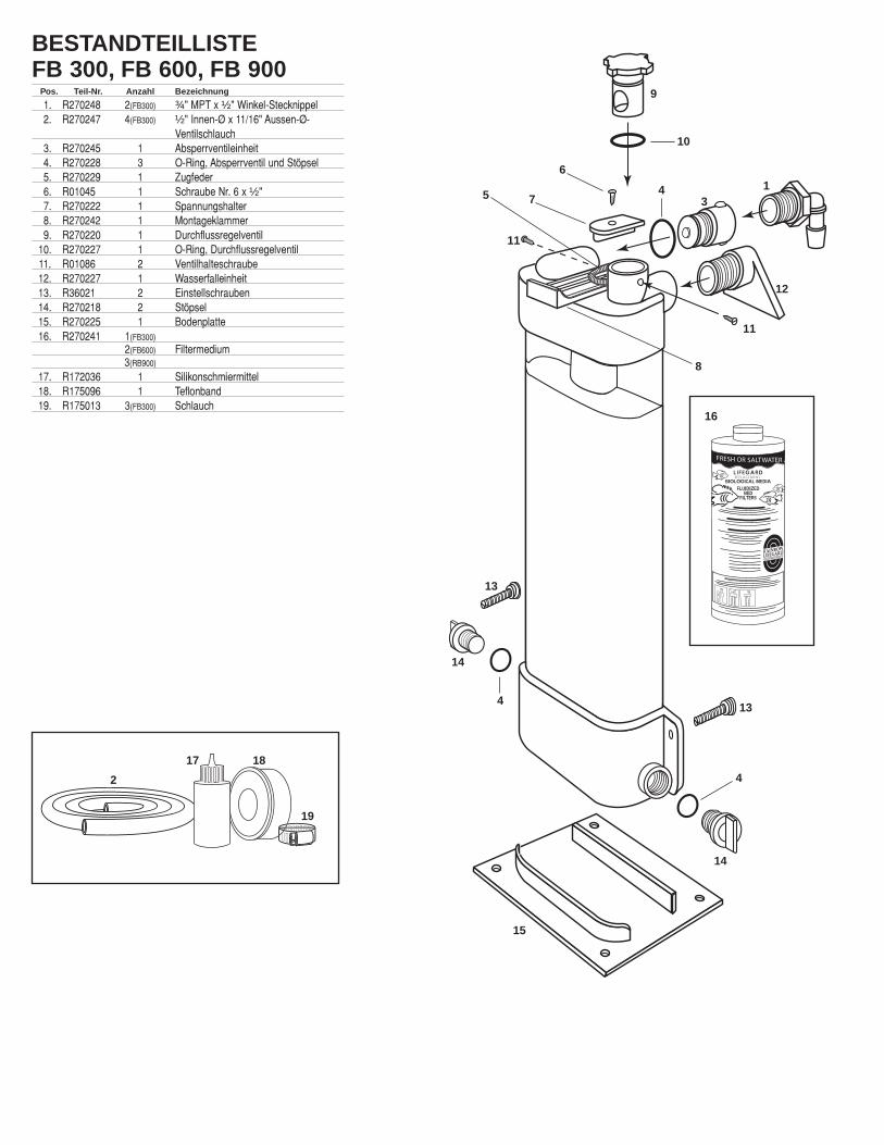
BESTANDTEILLISTEFB 300, FB 600, FB 900
Pos. Teil-Nr. Anzahl Bezeichnung
1. R270248 2(FB300) ¾" MPT x ½" Winkel-Stecknippel2. R270247 4(FB300) ½" Innen-Ø x 11/16" Aussen-Ø-
Ventilschlauch3. R270245 1 Absperrventileinheit4. R270228 3 O-Ring, Absperrventil und Stöpsel5. R270229 1 Zugfeder6. R01045 1 Schraube Nr. 6 x ½"7. R270222 1 Spannungshalter8. R270242 1 Montageklammer9. R270220 1 Durchflussregelventil
10. R270227 1 O-Ring, Durchflussregelventil11. R01086 2 Ventilhalteschraube12. R270227 1 Wasserfalleinheit13. R36021 2 Einstellschrauben14. R270218 2 Stöpsel15. R270225 1 Bodenplatte16. R270241 1(FB300)
2(FB600) Filtermedium3(RB900)
17. R172036 1 Silikonschmiermittel18. R175096 1 Teflonband19. R175013 3(FB300) Schlauch
FRESH OR SALTWATER AQUARIU
L I F E GA R D R EPLACEMENT
BIOLOGICAL MEDIAFLUIDIZED BED FILTERS
RAINBOWLIFEGARD
®
AQUARIUM PRODUCTS
9
10
6
7
8
16
17 18
19
1
2
34
4
4
5
11
11
12
13
13
14
14
15
FILTRO DE LECHO FLUIDIFICADO LIFEGARDHOJA DE INSTRUCCIONES FB 300, FB 600, FB 900
INTRODUCCIÓNDebido a suforma espe-cial, el Filtrode Lecho Flui-d i f i cado de Lifegard es ex-tremadamenteeficiente unfiltro "biológi-co" de grancapacidad. Los organismos de acuarioexcretan amoniaco tóxico como un excre-mento metabólico y también se producemás amoniaco cuando los alimentos yotras materias orgánica se descomponen.Este amoniaco (NH3) tóxico es convertidoen otro producto tóxico, nitrito (N02), porlas especies Nitrosómonas de bacteria. Elnitrito a su vez es convertido entonces porla especie Notrobacter de bacteria en unproducto relativamente no tóxico llamadonitrato (N03). Este proceso se conocecomo "nitrificación".Un filtro "biológico" es un recipiente dondeocurre la nitrificación y se eliminan losdeshechos solubles. La bacteria beneficiosa se quedaen el medio de filtración en el filtro de lecho fluidifica-do de Lifegard, creando una película fina alrededor delos granos de arena, El agua se bombea de la unidad,levantando la arena en el "lecho fluidificado". La bac-teria beneficiosa que se queda en el medio de fil-tración atrae los desechos disueltos (amoniaco y nitri-to), el oxigeno que proporciona el dispositivo exclusivode cascada de agua de Rainbow y otros alimentosnecesarios del agua en movimiento se convierten ennitrato, un producto químico relativamente inofensivo.Los granos de arena están en continuo movimiento enel agua, lo que da como resultado una excelentecapacidad de transporte entre el liquido y la películade bacteria en el medio de filtración. El área de super-ficie enormemente alta, junto con esta excelentecapacidad de transporte, crea el ambiente ideal parael cultivo de bacteria. Además, los granos de arena,golpeándose entre sí frecuentemente, retiran losdesechos excesivos proporcionando una función deautolimpieza, lo que crea nuevas áreas para el cultivo de bacteria. El Filtro de LechoFluidificado Lifegard ha sido probado y, también se ha verificado que proporciona el aguacon el más alto nivel de calidad y responde de forma rápida y eficiente a cambios severosen niveles de amoniaco, producidos por el exceso de alimentos o por la introducción dedemasiados peces al mismo tiempo. Para adquirir la mejor calidad de agua, un filtro delecho fluidificado de Lifegard deberá ser parte del sistema.
CAPACIDAD Por favor, preste atención al mapa siguiente para dimensionar adecuadamente el Filtro deLecho Fluidificado Lifegard a su sistema acuático.MODELO TAMAÑO DEL SISTEMA PESO DE MEDIO DE FILTRACIÓN ÁREA SUPERFICIAL
FB 300 A partir de 300 Galones 3 Lbs. 214 ft2
FB 600 A partir de 600 Galones 6 Lbs. 428 ft2
FB 900 A partir de 900 Galones 9 Lbs. 642 ft2 Pueden conectarse conjuntamente múltiples unidades para instalaciones de gran volumen o sistemascon los bio-cargas sumamente altas
LA TASA DE PASO El Filtro de Lecho Fluidificado de Lifegard es muy eficaz con tasas bajas. Las tasas depaso más bajas incrementan el tiempo de contacto entre las bacterias y el amoníaco tóx-ico y los compuestos de nitrito que ellas utilizan.
MADURACIÓN El Filtro de Lecho Fluidificado de Lifegard puede instalarse en un periodo de tiempo corto,sin embargo, la maduración biológica lleva bastante más tiempo. En la mayoría de loscasos, el periodo de maduración no debería llevar más de 40 días. Durante este periodo,las mismas bacterias de nitrificación se unen al medio de filtración en e filtro.Este periodo de maduración puede reducirse en gran medida introduciendo vivas en su filtro las bacte-rias de nitrificación mediante una pequeña cantidad de detrito procedente de un acuario maduro, o poradición de productos químicos específicos. Rogamos consultar con su distribuidor local para mayor infor-mación. Compruebe diariamente elagua de su acuario durante losprimeros 40 días para asegurarsede que el ciclo de nitrificación hatenido lugar y se ha completado.
BOMBAS MECÁNICAS DE EXTRACCIÓN RECOMENDADAS FABRICANTE MODELO DE BOMBA FILTRO DE LECHO FLUIDIZADO
HAGEN AQUACLEAR #301 FB 300, FB 600, FB 900, RÍO AQUA PUMP #200 FB 300
#400 FB 600 #600 FB 900
OTTO PH 600 FB 300, FB 600, PH 800 FB 900
AQUARIUM SYSTEMS MAXI-JET MJ 500 FB 900 MJ 750 FB 900
MARINELAND PENGUIN #550 FB 300, FAB 600, #660 FB 900
TETRA SECOND NATURE #640 FB 300, FB 600, FB 900, PENN-PLAX SHARK SK-13 FB 300, FB 600, FB 900,
Las recomendaciones de bomba arriba indicadas representan el mínimo que se exige para operarlos filtros. Aunque pueden usarse bombas mayores, la válvula de retención de paso debe ajustarsede modo correspondiente. La bomba Quiet One o cualquier bomba de accionamiento magnéticopueden también usarse si se instalan una válvula de desviación en el sistema de modo que sólo sedesvíe al filtro una parte del paso de la bomba.
OPCIONES DE INSTALACIÓN Nota: Si se desea, la instalación de tuberías duras puede reem-plazarse por tuberías flexibles.Elija una de las siguientes opciones y siga las instruccionesapropiadas.
1. COLGANDO EN EL ACUARIO A. Atornille tapones a cada lado del colector inferior. Asegúresede que los anillos en "o" de los tapones asientan adecuada-mente. Los accesos de entrada inferiores no se necesitan eneste tipo de instala-ciones.B. Atornille el conjuntode la válvula de retenciónen el acceso de entradasuperior. Asegúrese deque el anillo en "O" de laválvula de retención asien-ta adecuadamente.C. Envuelva la cinta deteflón a las roscas machosde un codo dentado de ¾ xMPT ½ pulgadas y la cas-cada de agua. Envuelvacada accesorio 5-7 vecescon la cinta de teflón. Paraeste tipo de instalaciónsólo se necesita un cododentado de ¾ x MPT ½pulgadas.D. Atornille el codo dentado de¾ x MPT ½ pulgadas de válvulaen el conjunto de la válvula deretención situada en el de entra-da superior. Atornille el codo demodo que la parte del dentadoapunte abajo hacia el agua delacuario.E. Atornille el conjunto de lacascada de agua en el accesode salida situado en la partesuperior del filtro. Curvas deamoníaco y nitrito que resultande la aclimatación de un filtrobiológico con especies acuáticas.F. Instale el filtro al lado o detrás delacuario empujando el resorte de laconsola para el montaje situada en laparte superior del filtro con su dedopulgar y colgando la unidad sobre elborde del acuario. Puede ser nece-sario mover la parte triangular del con-junto de la cascada de agua a un lado,de modo que pueda empujarse la con-sola para el montaje lo bastante lejoscomo para limpiar la moldura en elborde superior del acuario.G. Asegúrese de que la unidad estácompletamente nivelada ajustando lostornillos blancos situados a cada ladodel filtro.H. Desmonte los tornillos sujetadores de la válvula de retención depaso situada en la parte superior del filtro.I. Tire de la válvula de retención de paso hacia arriba verticalmente ydesmóntela.J. Adicione todo el medio en el filtro a través de la cámara de la válvu-la. Limpie con un paño seco cualquier medio que pueda haber en lacámara de la válvula. Lubrifique la válvula y la cámara de la válvulacon el lubricante de silicona suministrado con la unidad.
SANDGRAIN
CO2O2
NH3AMMONIA
NO3NITRATE
NO2NITRITE
BACTERIALAYER
–
–
24
21
18
15
12
9
6
3
00 5 10 15 20 25 30 35 40
AMMONIA-NNITRITE-N FILTER
ACCLIMATION
TIME IN DAYS
(mg-
N/I)
The ammomia and nitrite curves that result from acclimation of a biological filter with aquatic species.
LIFEGARD®FLUIDIZEDBED FILTER
RAINBOW
LIFEGARD®
FLUIDIZEDBED FILTER
RAINBOW
LIFEGARD®FLUIDIZEDBED FILTER
RAINBOW
LIFEGARD®
FLUIDIZEDBED FILTER
RAINBOW
LIFEGARD®FLUIDIZBED
RAINBOW
A
BD
EF
G
H
I
J
SAND
SAND
ORGANIC
NITROGEN
DISSOLVED
OXYGEN
O
AMMONIA
NH 3
NITRIT
ENO 2
NITRATE
NO 3
BACTERIA
NITROSOMONASBACTERIA
NITROBACTERBACTERIA
2
–
–
Nitrógeno
Orgánico
Amoníaco
NH3
Nitrito
NO 2_
Nitrato
NO 3_
Oxígeno
DisueltoO2
Arena
Arena
AMONIACO
NITRITO
NITRATO
GRANODE ARENA
CAPA DEBACTERIA
AMONÍCO-NNITRITO-N FILTRO DE
ACLIMATACION
TIEMPO EN DIAS

K. Instale de nuevo la válvula deretención de paso en la cámarade la válvula asegurándose deque el anillo en "O" asienta ade-cuadamente y de que todas laspartes están libre de cualquierdesecho o medio.L. Atornille los dos tornillos suje-tadores de la válvula.M. Instale la bomba mecánica deextracción (no incluida en launidad) en el acuario en la posi-ción deseada y siguiendo lasinstrucciones del fabricante de la bomba.N. Una un extremo de la tubería flexible de ½ ID x 11/16 pulgadasal lado de salida de la bomba mecánica de extracción.O. Una el otro extremo de la tubería flexible al codo dentado de ¾MPT x ½ pulgadas situado en el lado de entrada superior del filtro.En la mayoría de los casos, la tubería flexible necesita ser cortadaa la longitud apropiada.P. Ajuste la válvula de retención de paso a la posición "desconex-ión" girando la válvula en el sentido de las agujas del reloj hastaque se detenga. Tenga en cuenta que, como rasgo de seguri-dad, siempre pasará un poco de agua a través de la válvula deretención de paso incluso en la posición "desconexión".Q. Conecte la bomba y observe el llenado del filtro con agua.Desenchufe rápidamente la bomba si nota que todo el lecho dearena se mueve hacia arriba por el filtro en forma de agregado.Espere varios minutos para que escape el aire y el medio sedeposite en el fondo del filtro. Conecte de nuevo la bomba yobserve el llenado del filtro con agua y la purga de aire restantedel sistema.R. Ajuste despacio la válvula de retención de paso de modoque el medio esté "fluidizado" hasta el "nivel máximo deoperación" indicado en la cámara translúcida. No ajuste endemasía la válvula de modo que el nivel de fluidización sea mayor que este "nivel máximo deoperación" o en caso contrario el medio puede escapar en el sistema del acuario. Sin embargo, siesto ocurre, no se preocupe si alguna parte del medio de filtración entra en el acuario. El medio defiltración es completamente inerte y no causará daños a sus animales acuáticos o plantas. La válvu-la de retención de paso posee un alto grado de reacción y es sensible al cambio más ligero de posi-ción. Haga ajustes muy ligeros (1/16 pulgadas) y después de cada ajuste espere unos pocos minu-tos a que cambie el nivel del lecho fluidizado.
2. AL LADO DEL ACUARIO2A. Coloque el filtro sobre su base y en la situación deseada allado del acuario. Asegúrese de que la unidad está nivelada enla base.2B. Atornille los taponesa cada lado de la basedel agregado. Asegúresede que los anillos en "O"de los tapones asientanadecuadamente. Losaccesos de entrada infe-riores no se necesitan eneste tipo de instalación.2C. Atornille el conjunto de la válvula de retención en la entra-da superior. Asegúrese de que el anillo en "O" de la válvula deretención asienta adecuadamente.2D. Envuelva la cinta de teflón a las roscas machos de los doscodos dentados de ¾ MPT x ½ pulgadas suministrados comoaccesorios. Envuelva cada accesorio 5-7 veces con la cinta deteflón.2E. Atornille un accesorio de codo dentado de ¾ MPT x ½ pul-gadas en el conjunto de la válvula de retención situada en laentrada superior. Atornille el codo de modo que la parte deldentado apunte hacia arriba en dirección vertical. Atornille elotro accesorio de codo en el acceso de salida situado en laparte superior de la unidad y alinee directamente la parte dedentado hacia arriba en dirección vertical.2F. Desmonte los tornillos sujetadores de la válvula deretención de paso situada en el lado de salida superior delfiltro. Véanse los dibujos de la instalación en los pasos 2F a2J en la sección #1 (Colgando en el acuario).2G. Tire de la válvula de retención de paso hacia arriba ver-ticalmente y desmóntela.2H. Adicione todo el medio en el filtro a través de la cámarade la válvula. Limpie con un paño seco cualquier medio quepueda haber en la cámara de la válvula. Lubrifique la válvula y lacámara de la válvula con el lubricante de silicona suministradocon la unidad2I. Instale de nuevo la válvula de retención de paso en la cámarade la válvula asegurándose de que el anillo en "O" asienta ade-cuadamente y todas las partes están libre de cualquier desechoo medio de filtración.2J. Atornille los dos tornillos sujetadores de la válvula.2K. Instale la bomba mecánica de extracción (no incluida en launidad) en el acuario en la posición deseada y siguiendo lasinstrucciones del fabricante de la bomba.2L. Una un extremo de la tubería flexible de ½ ID x 11/16 pulgadas al lado de salida de la bombamecánica de extracción.2M. Una el otro extremo de la tubería flexible al codo dentado de ¾ MPT x ½ pulgadas ID x 11/16
situado en el lado de entrada superior del filtro. Corte la tubería cortada a la longitud apropiada. Unauna abrazadera para manguera y apriétela de modo correspondiente.
2N. Una el extremo de la tubería flexi-ble al codo dentado de ¾ MPT x ½ pul-gadas situado en el lado de entradasuperior del filtro. Una una abrazaderapara manguera y apriétela de modo cor-respondiente.2O. Coloque el otro extremo de latubería flexible arriba y encima del ladoo detrás del acuario de modo que elagua retorne al acuario y agite la super-ficie para airear el sistema. En algunoscasos puede ser deseable conectar latubería flexible a un tubo "U" o "J" deplástico rígido (no suministrado conesta unidad) que cuelgue del acuario.Una una abrazadera para manguera yapriétela de modo correspondiente.2P. Siga cuidadosamente los pasos P,Q y R de la sección #1 (Colgando en el acuario)
3. COLGANDO EN EL FILTRO ACUÁTICO/SECO 3A. Siga cuidadosamente todos los pasos de la sección #1 (Colgando en el acuario)
4. DEBAJO DEL ACUARIO CON UN SISTEMA DE LIFEGARD 4A. Coloque el filtro sobre su base y en la situación deseada junto al sistema modular Lifegard. Launidad debe posi-cionarse de modoque constituya lafase final en el sis-tema.4B. Apague labomba y desagüecompletamente elSistema de Lifegardy tuberías.4C. Atornille el con-junto de la válvula deretención en el acce-so de entrada en ellado derecho de labase del agregado.Asegúrese de que elanillo "O" asientaadecuadamente.4D. Atornille untapón en el ladoizquierdo de la base del agregado.Asegúrese de que el anillo "O" asientaadecuadamente.4E. Instale una tubería de válvula dedesviación y "te" después del Sistemade Lifegard que desvíe sólo una partedel agua del Sistema de Lifegard y en elacceso de entrada en el lado derecho dela base del agregado. Ello puedelograrse con cualquier tubería PVC rígi-da o con tubería de vinilo flexible.4F. Atornille el otro tapón en el accesode entrada superior en el lado izquierdode la unidad. Asegúresede que el anillo en "O"asienta adecuadamente.El acceso de entrada no senecesita en este tipo deinstalación.4G. Envuelva la cinta deteflón a las roscas machosde un codo dentado de ¾MPT x ½ pulgadas.Envuelva el accesorio 5-7veces con la cinta deteflón.4H. Atornille el accesoriode codo dentado de ¾MPT x ½ pulgadas en ellado derecho superior delfiltro. Posicione la parte del dentado hacia arriba en dirección vertical4I. Siga cuidadosamente los pasos 2N. Y 20 de la sección #2 (Al lado del acuario)4J. Adicione el medio a la unidad sigu-iendo los pasos H, l, J, K y L en la sec-ción #1 (Colgando en el acuario)
LIFEGARD®
FLUIDIZEDBED FILTER
RAINBOW
LIFEGARD®FLUIDIZEDBED FILTER
RAINBOW
M&N
O
LIFEGARD®FLUIDIZEDBED FILTER
RAINBOW
AQUARIUM
LIFEGARD MODULAR SYSTEM
LIFEGARD®
FLUIDIZEDBED FILTER
RAINBOW
LIFEGARD®
FLUIDIZEDBED FILTER
RAINBOW
To Aquarium
By-Pass Valve "Tee"
L
M, N& O
P
2A
2C
2E
3A
4A
4C/4D
4E
4F
4H
K
Válvula de desviación “Te”
ACUARIO
AL ACUARIO
2B
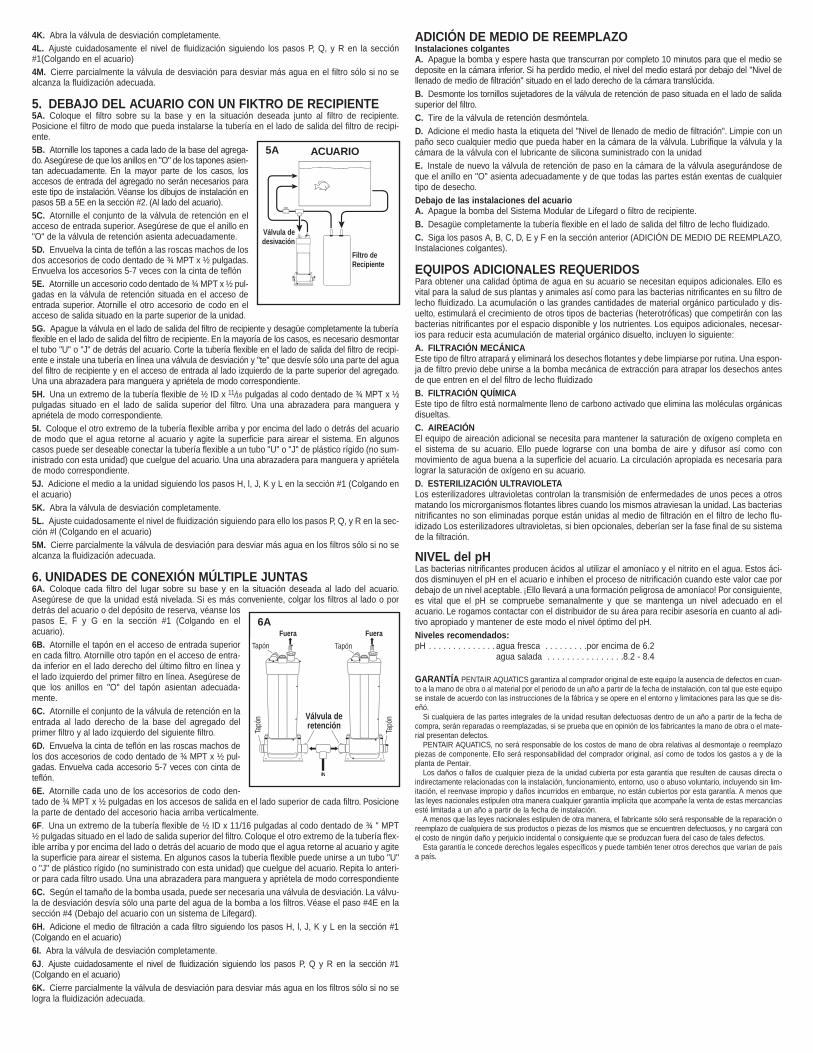
4K. Abra la válvula de desviación completamente.4L. Ajuste cuidadosamente el nivel de fluidización siguiendo los pasos P, Q, y R en la sección#1(Colgando en el acuario)4M. Cierre parcialmente la válvula de desviación para desviar más agua en el filtro sólo si no sealcanza la fluidización adecuada.
5. DEBAJO DEL ACUARIO CON UN FIKTRO DE RECIPIENTE5A. Coloque el filtro sobre su la base y en la situación deseada junto al filtro de recipiente.Posicione el filtro de modo que pueda instalarse la tubería en el lado de salida del filtro de recipi-ente.5B. Atornille los tapones a cada lado de la base del agrega-do. Asegúrese de que los anillos en "O" de los tapones asien-tan adecuadamente. En la mayor parte de los casos, losaccesos de entrada del agregado no serán necesarios paraeste tipo de instalación. Véanse los dibujos de instalación enpasos 5B a 5E en la sección #2. (Al lado del acuario).5C. Atornille el conjunto de la válvula de retención en elacceso de entrada superior. Asegúrese de que el anillo en"O" de la válvula de retención asienta adecuadamente.5D. Envuelva la cinta de teflón a las roscas machos de losdos accesorios de codo dentado de ¾ MPT x ½ pulgadas.Envuelva los accesorios 5-7 veces con la cinta de teflón5E. Atornille un accesorio codo dentado de ¾ MPT x ½ pul-gadas en la válvula de retención situada en el acceso deentrada superior. Atornille el otro accesorio de codo en elacceso de salida situado en la parte superior de la unidad.5G. Apague la válvula en el lado de salida del filtro de recipiente y desagüe completamente la tuberíaflexible en el lado de salida del filtro de recipiente. En la mayoría de los casos, es necesario desmontarel tubo "U" o "J" de detrás del acuario. Corte la tubería flexible en el lado de salida del filtro de recipi-ente e instale una tubería en línea una válvula de desviación y "te" que desvíe sólo una par te del aguadel filtro de recipiente y en el acceso de entrada al lado izquierdo de la parte superior del agregado.Una una abrazadera para manguera y apriétela de modo correspondiente.5H. Una un extremo de la tubería flexible de ½ ID x 11/16 pulgadas al codo dentado de ¾ MPT x ½pulgadas situado en el lado de salida superior del filtro. Una una abrazadera para manguera yapriétela de modo correspondiente.5I. Coloque el otro extremo de la tubería flexible arriba y por encima del lado o detrás del acuariode modo que el agua retorne al acuario y agite la superficie para airear el sistema. En algunoscasos puede ser deseable conectar la tubería flexible a un tubo "U" o "J" de plástico rígido (no sum-inistrado con esta unidad) que cuelgue del acuario. Una una abrazadera para manguera y apriételade modo correspondiente.5J. Adicione el medio a la unidad siguiendo los pasos H, l, J, K y L en la sección #1 (Colgando enel acuario)5K. Abra la válvula de desviación completamente.5L. Ajuste cuidadosamente el nivel de fluidización siguiendo para ello los pasos P, Q, y R en la sec-ción #l (Colgando en el acuario)5M. Cierre parcialmente la válvula de desviación para desviar más agua en los filtros sólo si no sealcanza la fluidización adecuada.
6. UNIDADES DE CONEXIÓN MÚLTIPLE JUNTAS 6A. Coloque cada filtro del lugar sobre su base y en la situación deseada al lado del acuario.Asegúrese de que la unidad está nivelada. Si es más conveniente, colgar los filtros al lado o pordetrás del acuario o del depósito de reserva, véanse lospasos E, F y G en la sección #1 (Colgando en elacuario).6B. Atornille el tapón en el acceso de entrada superioren cada filtro. Atornille otro tapón en el acceso de entra-da inferior en el lado derecho del último filtro en línea yel lado izquierdo del primer filtro en línea. Asegúrese deque los anillos en "O" del tapón asientan adecuada-mente.6C. Atornille el conjunto de la válvula de retención en laentrada al lado derecho de la base del agregado delprimer filtro y al lado izquierdo del siguiente filtro.6D. Envuelva la cinta de teflón en las roscas machos delos dos accesorios de codo dentado de ¾ MPT x ½ pul-gadas. Envuelva cada accesorio 5-7 veces con cinta deteflón.6E. Atornille cada uno de los accesorios de codo den-tado de ¾ MPT x ½ pulgadas en los accesos de salida en el lado superior de cada filtro. Posicionela parte de dentado del accesorio hacia arriba verticalmente.6F. Una un extremo de la tubería flexible de ½ ID x 11/16 pulgadas al codo dentado de ¾ " MPT½ pulgadas situado en el lado de salida superior del filtro. Coloque el otro extremo de la tubería flex-ible arriba y por encima del lado o detrás del acuario de modo que el agua retorne al acuario y agitela superficie para airear el sistema. En algunos casos la tubería flexible puede unirse a un tubo "U"o "J" de plástico rígido (no suministrado con esta unidad) que cuelgue del acuario. Repita lo anteri-or para cada filtro usado. Una una abrazadera para manguera y apriétela de modo correspondiente6C. Según el tamaño de la bomba usada, puede ser necesaria una válvula de desviación. La válvu-la de desviación desvía sólo una parte del agua de la bomba a los filtros. Véase el paso #4E en lasección #4 (Debajo del acuario con un sistema de Lifegard).6H. Adicione el medio de filtración a cada filtro siguiendo los pasos H, l, J, K y L en la sección #1(Colgando en el acuario)6I. Abra la válvula de desviación completamente.6J. Ajuste cuidadosamente el nivel de fluidización siguiendo los pasos P, Q y R en la sección #1(Colgando en el acuario)6K. Cierre parcialmente la válvula de desviación para desviar más agua en los filtros sólo si no selogra la fluidización adecuada.
ADICIÓN DE MEDIO DE REEMPLAZO Instalaciones colgantes A. Apague la bomba y espere hasta que transcurran por completo 10 minutos para que el medio sedeposite en la cámara inferior. Si ha perdido medio, el nivel del medio estará por debajo del "Nivel dellenado de medio de filtración" situado en el lado derecho de la cámara translúcida.B. Desmonte los tornillos sujetadores de la válvula de retención de paso situada en el lado de salidasuperior del filtro.C. Tire de la válvula de retención desmóntela.D. Adicione el medio hasta la etiqueta del "Nivel de llenado de medio de filtración". Limpie con unpaño seco cualquier medio que pueda haber en la cámara de la válvula. Lubrifique la válvula y lacámara de la válvula con el lubricante de silicona suministrado con la unidadE. Instale de nuevo la válvula de retención de paso en la cámara de la válvula asegurándose deque el anillo en "O" asienta adecuadamente y de que todas las partes están exentas de cualquiertipo de desecho.Debajo de las instalaciones del acuario A. Apague la bomba del Sistema Modular de Lifegard o filtro de recipiente.B. Desagüe completamente la tubería flexible en el lado de salida del filtro de lecho fluidizado.C. Siga los pasos A, B, C, D, E y F en la sección anterior (ADICIÓN DE MEDIO DE REEMPLAZO,Instalaciones colgantes).
EQUIPOS ADICIONALES REQUERIDOSPara obtener una calidad óptima de agua en su acuario se necesitan equipos adicionales. Ello esvital para la salud de sus plantas y animales así como para las bacterias nitrificantes en su filtro delecho fluidizado. La acumulación o las grandes cantidades de material orgánico particulado y dis-uelto, estimulará el crecimiento de otros tipos de bacterias (heterotróficas) que competirán con lasbacterias nitrificantes por el espacio disponible y los nutrientes. Los equipos adicionales, necesar-ios para reducir esta acumulación de material orgánico disuelto, incluyen lo siguiente:A. FILTRACIÓN MECÁNICA Este tipo de filtro atrapará y eliminará los desechos flotantes y debe limpiarse por rutina. Una espon-ja de filtro previo debe unirse a la bomba mecánica de extracción para atrapar los desechos antesde que entren en el del filtro de lecho fluidizadoB. FILTRACIÓN QUÍMICA Este tipo de filtro está normalmente lleno de carbono activado que elimina las moléculas orgánicasdisueltas.C. AIREACIÓN El equipo de aireación adicional se necesita para mantener la saturación de oxígeno completa enel sistema de su acuario. Ello puede lograrse con una bomba de aire y difusor así como conmovimiento de agua buena a la superficie del acuario. La circulación apropiada es necesaria paralograr la saturación de oxígeno en su acuario.D. ESTERILIZACIÓN ULTRAVIOLETA Los esterilizadores ultravioletas controlan la transmisión de enfermedades de unos peces a otrosmatando los microrganismos flotantes libres cuando los mismos atraviesan la unidad. Las bacteriasnitrificantes no son eliminadas porque están unidas al medio de filtración en el filtro de lecho flu-idizado Los esterilizadores ultravioletas, si bien opcionales, deberían ser la fase final de su sistemade la filtración.
NIVEL del pH Las bacterias nitrificantes producen ácidos al utilizar el amoníaco y el nitrito en el agua. Estos áci-dos disminuyen el pH en el acuario e inhiben el proceso de nitrificación cuando este valor cae pordebajo de un nivel aceptable. ¡Ello llevará a una formación peligrosa de amoníaco! Por consiguiente,es vital que el pH se compruebe semanalmente y que se mantenga un nivel adecuado en elacuario. Le rogamos contactar con el distribuidor de su área para recibir asesoría en cuanto al adi-tivo apropiado y mantener de este modo el nivel óptimo del pH.Niveles recomendados:pH . . . . . . . . . . . . . . agua fresca . . . . . . . . .por encima de 6.2
agua salada . . . . . . . . . . . . . . . .8.2 - 8.4
GARANTÍA PENTAIR AQUATICS garantiza al comprador original de este equipo la ausencia de defectos en cuan-to a la mano de obra o al material por el periodo de un año a partir de la fecha de instalación, con tal que este equipose instale de acuerdo con las instrucciones de la fábrica y se opere en el entorno y limitaciones para las que se dis-eñó.
Si cualquiera de las partes integrales de la unidad resultan defectuosas dentro de un año a partir de la fecha decompra, serán reparadas o reemplazadas, si se prueba que en opinión de los fabricantes la mano de obra o el mate-rial presentan defectos.
PENTAIR AQUATICS, no será responsable de los costos de mano de obra relativas al desmontaje o reemplazopiezas de componente. Ello será responsabilidad del comprador original, así como de todos los gastos a y de laplanta de Pentair.
Los daños o fallos de cualquier pieza de la unidad cubierta por esta garantía que resulten de causas directa oindirectamente relacionadas con la instalación, funcionamiento, entorno, uso o abuso voluntario, incluyendo sin lim-itación, el reenvase impropio y daños incurridos en embarque, no están cubiertos por esta garantía. A menos quelas leyes nacionales estipulen otra manera cualquier garantía implícita que acompañe la venta de estas mercancíasesté limitada a un año a partir de la fecha de instalación.
A menos que las leyes nacionales estipulen de otra manera, el fabricante sólo será responsable de la reparación oreemplazo de cualquiera de sus productos o piezas de los mismos que se encuentren defectuosos, y no cargará conel costo de ningún daño y perjuicio incidental o consiguiente que se produzcan fuera del caso de tales defectos.
Esta garantía le concede derechos legales específicos y puede también tener otros derechos que varían de paísa país.
AQUARIUM
CANISTERFILTER
By-PassValve
IN
OUTPlug Plug
Plug
Plug
OUT
Check Valves
5A
6A
ACUARIO
Filtro deRecipiente
Válvula de desivación
Fuera Fuera
Tapón
Tapó
n
Tapó
n
Tapón
Válvula deretención
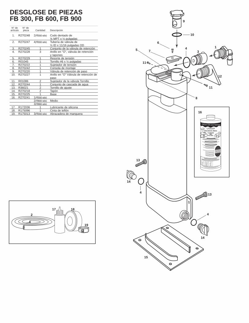
DESGLOSE DE PIEZASFB 300, FB 600, FB 900
N° de N° de artículo pieza Cantidad Descripción
1. R270248 2(FB300 sólo) Codo dentado de ¾ MPT x ½ pulgadas
2. R270247 4(FB300 sólo) Tubería de válvula de½ ID x 11/16 pulgadas OD
3. R270245 1 Conjunto de la válvula de retención4. R270228 3 Anillo en "O", válvula de retención
y tapones5. R270229 1 Resorte de tensión 6. R01045 1 Tornillo #6 x ½ pulgadas7. R270222 1 Sujetador de tensión 8. R270242 1 Consola de montaje 9. R270220 1 Válvula de retención de paso 10. R270227 1 Anillo en "O" Válvula de retención de
paso 11. R01086 2 Sujetador de la válvula Tornillo 12. R270244 1 Conjunto de cascada de agua 13. R36021 2 Tornillo de ajuste 14. R270218 2 Tapón 15. R270225 1 Base 16. R270241 1(FB300 sólo)
2(FB600 sólo) Medio3(FB900 sólo)
17. R172036 1 Lubricante de silicona 18. R175096 1 Cinta de teflón 19. R175013 3(FB300 sólo) Abrazadera de manguera
FRESH OR SALTWATER AQUARIU
L I F E GA R D R EPLACEMENT
BIOLOGICAL MEDIAFLUIDIZED BED FILTERS
RAINBOWLIFEGARD
®
AQUARIUM PRODUCTS
9
10
6
7
8
16
17 18
19
1
2
34
4
4
5
11
11
12
13
13
14
14
15
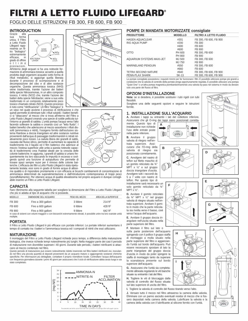
FILTRI A LETTO FLUIDO LIFEGARD®
FOGLIO DELLE ISTRUZIONI FB 300, FB 600, FB 900
INTRODUCTIONGrazie allasua formaunica, il Filtroa Letto FluidoLifegard rapp-resenta un fil-tro "biologico"estremamenteefficace, ingrado di offrireo t t i m eprestaz ion i .All'interno degli acquari si ha una notevole for-mazione di ammoniaca tossica: accanto a quellaprodotta dagli organismi acquatici sotto forma dirifiuti metabolici, si aggiunge quella liberatadurante il processo di scomposizione e didecomposizione del cibo e di altre sostanzeorganiche. Questa ammoniaca tossica (NH3)viene trasformata, tramite l'azione dei batteridella specie Nitrosomonas, in un altro compostotossico, il nitrito (NO2) che, tramite l'azione deibatteri della specie Nitrobacter, viene a sua voltatrasformato in un composto relativamente pocotossico chiamato nitrato (NO3). Questo processoè noto come "nitrificazione". Un filtro "biologico" èun vaso nel quale avviene il processo di nitrificazione e chequindi permette di eliminare tutti i rifiuti solubili. I batteri benefi-ci si "attaccano" al mezzo che si trova all'interno del Filtro aLetto Fluido Lifegard creando una specie di sottile pellicola tut-t'intorno ai granelli di sabbia. L'unità pompa l'acqua verso l'altofacendo sollevare la sabbia e creando così un "letto fluido". Ibatteri benefici che aderiscono al mezzo assorbono i rifiuti dis-solti (ammoniaca e nitriti), l'ossigeno fornito dall'esclusivo sis-tema Rainbow a doccia triangolare ed altre sostanze nutritiveprovenienti dall'acqua di passaggio trasformandoli in nitrati rel-ativamente poco tossici. La caduta libera dei granelli di sabbi,causata dal flusso idrico, permette di aumentare la capacità ditrasferimento tra il liquido ed il film batterico che aderisce almezzo: l'estesa superficie utile unita a questa notevole capac-ità di trasferimento crea l'habitat ideale per la crescita dellecolonie batteriche. In aggiunta, i granelli di sabbia si urtano fre-quentemente tra loro staccando le impurità in eccesso e svol-gendo quindi una funzione di autopulitura che permette ditrovare spazi sempre nuovi per il rinnovo delle colonie bat-teriche. L'efficacia dei filtri a Letto Fluido Lifegard è stata ripetu-tamente testata: essi sono in grado di fornire acqua di altissi-ma qualità e di rispondere prontamente e con efficacia ai bruschi cambiamenti di concentrazione diammoniaca determinati da superalimentazione o dall'introduzione contemporanea di troppi pesci(sovraffollamento). Per ottenere acqua di qualità elevatissima nel proprio acquario è dunque consigli-abile inserire un Filtro a Letto Fluido Lifegard.
CAPACITÀFare riferimento alla seguente tabella per scegliere la dimensione del Filtro a Letto Fluido Lifegardche più si adatta al tipo di acquario che si possiede.MODELLO DIMENSIONE DELL'ACQUARIO PESO DEL MEZZO AREA DELLA SUPERFICIE
FB 300 Fino a 300 galloni 3 libbre 214 ft2
FB 600 Fino a 600 galloni 6 libbre 428 ft2
FB 900 Fino a 900 galloni 9 libbre 642 ft2In caso di sistemi con volumi maggiori o con biocarichi estremamente elevati, è possibile unire tra loro svariate unitàmultiple.
PORTATAIl Filtro a Letto Fluido Lifegard è più efficace con portate inferiori. Le portate inferiori aumentano iltempo di contatto tra i batteri e l'ammoniaca tossica ed i composti di nitriti che essi utilizzano.
MATURAZIONEIl montaggio del Filtro a Letto Fluido Lifegard richiede poco tempo, a differenza della maturazionebiologica, che invece richiede tempi notevolmente più lunghi. Nella maggior parte dei casi il periododi maturazione non dovrebbe superare i 40 giorni. Durante tale periodo, i batteri nitrificanti si attac-cano al mezzo contenuto nel filtro.Questo periodo di maturazione può essere notevolmente ridotto inserendo nel filtro batteri nitrificanti vivi, inoculan-do nel filtro una piccola quantità di depositi provenienti da un acquario maturo o aggiungendo sostanze chimichespecifiche. Per informazioni più dettagliate, contattare il proprio rivenditore locale. Controllare l'acqua dell'acquariocon frequenza giornaliera durante i primi 40 giorni per assicurarsi che il ciclo di nitrificazione abbia avuto luogo e siastato completato.
POMPE DI MANDATA MOTORIZZATE consigliatePRODUTTORE MODELLO FILTRO A LETTO FLUIDO
HAGEN AQUACLEAR #301 FB 300, FB 600, FB 900RIO AQUA PUMP #200 FB 300
#400 FB 600#600 FB 900
OTTO PH 600 FB 300, FB 600PH 800 FB 900
AQUARIUM SYSTEMS MAXI-JET MJ 500 FB 300, FB 600MJ 750 FB 900
MARINELAND PENGUIN #550 FB 300, FB 600#660 FB 600
TETRA SECOND NATURE #640 FB 300, FB 600, FB 900PENN-PLAX SHARK SK-13 FB 300, FB 600, FB 900Le pompe consigliate possiedono i requisiti minimi per far funzionare i filtri. È possibile utilizzare pompe più grandi acondizione che la valvola di controllo della portata venga opportunamente regolata. È possibile utilizzare una pompa"Quiet One" o un'altra pompa magnetica piombando/inserendo una valvola by-pass nel sistema in modo da deviaresolo una parte del flusso al filtro.
OPZIONI D'INSTALLAZIONENota: se si desidera, è possibile sostituire i tubi rigidi con tubiflessibili.Scegliere una delle seguenti opzioni e seguire le istruzioni fornite.
1. INSTALLAZIONE SULL'ACQUARIOA. Avvitare i tappi su entrambi i lati del collettore inferiore.Assicurarsi che gli O-ring dei tappi siano posizionati corretta-mente. Questo tipo diinstallazione non richiedel'uso delle entrate postenella parte inferiore.B. Avvitare il gruppovalvola di ritegno nell'en-trata superiore. Assi-curarsi che l'O-ring dellavalvola di ritegno siaposizionato correttamente.C. Avvolgere del nastro diteflon sul filetto maschio diun gomito reticolato da ¾"MPT x ½" e sul gruppodoccia triangolare d'uscita.Avvolgere tutti i raccordi da5 a 7 volte con nastro diteflon. Per questo tipo diinstallazione sarà necessario unsolo gomito reticolato da ¾"MPT x ½".D. Avvitare il gomito reticolatoda ¾" MPT x ½" nel gruppovalvola di ritegno situato nell'en-trata superiore. Avvitare il gomi-to in modo che la parte reticola-ta sia rivolta verso il basso, cioèverso l'acqua dell'acquario.E. Avvitare il gruppo doccia tri-angolare nell'uscita situata nellaparte superiore del filtro.F. Montare il filtro sul lato osulla parte posteriore dell'acquariospingendo con il pollice il gruppo staffadi montaggio a molla situato nellaparte superiore del filtro e aggancian-do l'unità sul bordo dell'acquario. Puòessere necessario spostare di lato laparte triangolare del gruppo docciad'uscita in modo da poter spingere lastaffa di montaggio tanto da superarela scanalatura presente sul bordosuperiore dell'acquario.G. Assicurarsi che l'unità sia completa-mente allineata regolando le viti bianchesituate su entrambi i lati del filtro.H. Togliere le viti di bloccaggio dallavalvola di controllo del flusso situatasul lato superiore di uscita del filtro.I. Togliere la valvola di controllo del flusso tirando verso l'alto.J. Versare tutto il mezzo nel filtro attraverso la camera della valvola.Eliminare con un panno asciutto eventuali residui di mezzo che si fos-sero depositati nella camera della valvola. Lubrificare la valvola e lacamera della valvola con il lubrificante al silicone fornito con l'unità.
SANDGRAIN
CO2O2
NH3AMMONIA
NO3NITRATE
NO2NITRITE
BACTERIALAYER
–
–
SAND
SAND
ORGANIC
NITROGEN
DISSOLVED
OXYGEN
O
AMMONIA
NH 3
NITRIT
ENO 2
NITRATE
NO 3
BACTERIA
NITROSOMONASBACTERIA
NITROBACTERBACTERIA
2
–
–
24
21
18
15
12
9
6
3
00 5 10 15 20 25 30 35 40
AMMONIA-NNITRITE-N FILTER
ACCLIMATION
TIME IN DAYS
(mg-
N/I)
The ammomia and nitrite curves that result from acclimation of a biological filter with aquatic species.
LIFEGARD®FLUIDIZEDBED FILTER
RAINBOW
LIFEGARD®
FLUIDIZEDBED FILTER
RAINBOW
LIFEGARD®FLUIDIZEDBED FILTER
RAINBOW
LIFEGARD®
FLUIDIZEDBED FILTER
RAINBOW
LIFEGARD®FLUIDIZBED
RAINBOW
A
BD
EF
G
H
I
J

K. Rimontare la valvola di control-lo del flusso nella camera dellavalvola assicurandosi che l'O-ringsia posizionato correttamente eche tutti i componenti non pre-sentino impurità o residui dimezzo.L. Avvitare le due viti di bloccag-gio della valvola.M. Montare la pompa di mandatamotorizzata (non compresa nell'u-nità) nella posizione desideratadentro all'acquario seguendo le istruzioni fornite dal produttore dellapompa.N. Collegare un'estremità del tubo flessibile da ½"ID x 11/16" ODall'uscita della pompa elettrica.O. Collegare l'altra estremità del tubo flessibile al gomito reticolato da¾" MPT x ½" situato nella parte superiore di entrata del filtro. Nellamaggior parte dei casi, il tubo flessibile dovrà essere tagliato ad unalunghezza appropriata.P. Regolare la valvola di controllo del flusso sulla posizione"off" girandola completamente in senso orario fino all'arresto.Per motivi di sicurezza, è bene sapere che, anche nellaposizione "off", vi sarà sempre dell'acqua in transito attraversola valvola di controllo del flusso.Q. Collegare la pompa all'alimentazione ed osservare il filtromentre si riempie d'acqua. Scollegare subito la pompa se l'interoletto di sabbia si sposta verso il filtro in un blocco unico. Aspettarediversi minuti per permettere all'aria di uscire ed al mezzo didepositarsi sul fondo del filtro. Ricollegare la pompa e controllareche il filtro si riempia correttamente e che l'aria rimanente vengasfiatata dal sistema.R. Regolare lentamente la valvola di controllo del flusso inmodo che il mezzo si "fluidizzi" fino al "livello di massima operatività" indicato sulla camera traspar-ente. Non sovraregolare la valvola, altrimenti la fluidizzazione andrebbe oltre il "livello di massimaoperatività" ed il mezzo potrebbe finire nell'acquario. Se ciò dovesse accadere, non c'è da preoccu-parsi: il mezzo è completamente inerte e non danneggerà gli animali o le piante acquatiche dell'ac-quario. La valvola di controllo del flusso è estremamente sensibile ed è in grado di registrare ancheleggerissimi spostamenti di posizione. Effettuare lievissime regolazioni (1/16") e dopo ogni rego-lazione attendere alcuni minuti per osservare le variazioni di livello del letto fluido.
2. ACCANTO ALL'ACQUARIO2A. Porre il filtro nella posizione desiderata accanto all'ac-quario, appoggiandolo sul proprio basamento. Assicurarsi chel'unità sia allineata con il basamento.2B. Avvitare i tappi suentrambi i lati del collet-tore inferiore. Assicurarsiche gli o- ring dei tappisiano posizionati corret-tamente. Questo tipo diinstallazione non richiedel'uso delle entrate postenella parte inferiore.2C. Avvitare il gruppo valvola di ritegno nell'entrata superiore.Assicurarsi che l'O-ring della valvola di ritegno sia posizionatocorrettamente.2D. Avvolgere del nastro di teflon sul filetto maschio dei duegomiti reticolati da ¾" MPT x ½. Avvolgere tutti i raccordi da 5 a7 volte con nastro di teflon.2E. Avvitare uno dei gomiti reticolati da ¾" MPT x ½" al gruppovalvola di ritegno situato nell'entrata superiore. Avvitare il gomi-to in modo che la parte reticolata sia rivolta verso l'alto, inposizione verticale. Avvitare l'altro raccordo a gomito nell'uscitasituata nella parte superiore dell'unità ed allineare la parte reti-colata verso l'alto, in posizione verticale.2F. Togliere le viti di bloccaggio dalla valvola di controllo delflusso situata sul lato superiore di uscita del filtro. Per i puntida 2F a 2J fare riferimento alle figure della sezione #1(Installazione sull'acquario)2G. Togliere la valvola di controllo del flusso tirando versol'alto.2H. Versare tutto il mezzo nel filtro attraverso la cameradella valvola. Eliminare con un panno asciutto eventualiresidui di mezzo che si fossero depositati nella camera dellavalvola. Lubrificare la valvola e la camera della valvola con il lubri-ficante al silicone fornito con l'unità.2I. Rimontare la valvola di controllo del flusso nella camera dellavalvola assicurandosi che l'O-ring sia posizionato correttamente eche tutti i componenti non presentino impurità o residui di mezzo.2J. Avvitare le due viti di bloccaggio della valvola.2K. Montare la pompa di mandata motorizzata (non compresa nel-l'unità) nella posizione desiderata dentro all'acquario seguendo leistruzioni fornite dal produttore della pompa.2L. Collegare un'estremità del tubo flessibile da ½"ID x 11/16" ODsul lato dell'uscita della pompa di mandata motorizzata.2M. Collegare l'altra estremità del tubo flessibile al gomito reticolato da ¾" MPT x ½" situato nellaparte superiore di entrata del filtro. Tagliare il tubo flessibile ad una lunghezza appropriata. Montareuna fascetta per tubi e serrare opportunamente.
2N. Collegare il resto del tubo al gomitoreticolato da ¾" x ½" situato sul lato diuscita superiore del filtro. Montare unafascetta per tubi e serrare opportuna-mente.2O. Posizionare l'altra estremità deltubo flessibile in alto al di sopra del fian-co o del retro dell'acquario in modo chel'acqua ritorni nell'acquario e agiti lasuperficie per aerare il sistema. In alcunicasi può essere necessario collegare iltubo flessibile ad un tubo di plastica rigi-do a "U" o a "J" (non fornito con l'unità)da agganciare all'acquario. Montare unafascetta per tubi al tubo rigido e serrareopportunamente.2P. Seguire con attenzione i punti P, Q eR indicati nella sezione #1 (Installazionesull'acquario).
3. INSTALLAZIONE SUL FILTRO A UMIDO/SECCOSeguire attentamente tutti i punti indicati nella sezione #1 (Installazione sull'acquario).
4. SOTTO L'ACQUARIO CON UN SISTEMA LIFEGARD4A. Collocare il fil-tro nella posizionedesiderata accantoad un sistema mod-ulare, appoggiando-lo sul proprio basa-mento. L'unitàdovrebbe essereposizionata in modotale da rappre-sentare l'ultima fasedel sistema.4B. Scollegare lapompa e vuotarecompletamente ilsistema Lifegard etutte le tubature.4C. Avvitare il grup-po valvola di ritegnonell'entrata posta sullato destro del col-lettore inferiore.Assicurarsi che l'O-ring sia posizionatocorrettamente.4D. Avvitare un tappo sul lato destro delcollettore inferiore. Assicurarsi che l'O-ring sia posizionato correttamente.4E. Collegare/piombare una valvola by-pass ed un "T" dopo il sistema Lifegardche permetteranno di deviare solo unaparte dell'acqua proveniente dal sistemaLifegard e diretta all'entrata posta sul latodestro del collettore inferiore. Questaoperazione può essere effettuata sia uti-lizzando tubature rigide inPVC che con tubi flessibilivinilici.4F. Avvitare l'altro tapponell'entrata superiore postasul lato destro dell'unità.Assicurarsi che l'O-ring deltappo sia posizionato cor-rettamente. Questa entratanon viene utilizzata inquesto tipo di installazione.4G. Avvolgere del nastrodi teflon sul filetto maschiodi un gomito reticolato da¾" MPT x ½". Avvolgere ilraccordo da 5 a 7 volte connastro di teflon.4H. Avvitare il raccordo a gomito reticolato da ¾" MPT x ½" nel lato di uscita posto sul lato superi-ore destro del filtro. Posizionare la parte reticolata rivolta verso l'alto, in posizione verticale.4I. Seguire i punti 2N e 2O della sezione#2 (Accanto all'Acquario).
LIFEGARD®FLUIDIZEDBED FILTER
RAINBOW
M&N
O
LIFEGARD®FLUIDIZEDBED FILTER
RAINBOW
AQUARIUM
LIFEGARD MODULAR SYSTEM
LIFEGARD®
FLUIDIZEDBED FILTER
RAINBOW
LIFEGARD®
FLUIDIZEDBED FILTER
RAINBOW
To Aquarium
By-Pass Valve "Tee"
L
M, N& O
P
2A
2C
2E
3A
4A
4C/4D
4E
4F
4H
K
ACQUARIO
LIFEGARD SISTEMA MODULARE
All’acquario
Valvola by-pass Elemento a “T”
LIFEGARD®
FLUIDIZEDBED FILTER
RAINBOW
2B

4J. Versare il mezzo nell'unità seguendo i punti H, I, J, K e L della sezione #1 (Installazione sul-l'acquario).4K. Aprire completamente la valvola by-pass.4L. Regolare accuratamente la leva di fluidizzazione seguendo i punti P, Q e R della sezione #1(Installazione sull'acquario).4M. Regolare parzialmente la valvola by-pass per portare una quantità maggiore di acqua al filtrosolo in assenza di opportuna fluidizzazione.
5. SOTTO L'ACQUARIO CON FILTRO CILINDRICO5A. Collocare il filtro nella posizione desiderata accanto alfiltro cilindrico, appoggiandolo sul proprio basamento. Il fil-tro deve essere posizionato in modo da poter essere colle-gato sul lato di uscita del filtro cilindrico.5B. Avvitare i tappi su entrambi i lati del collettore inferi-ore. Assicurarsi che gli O-ring siano posizionati corretta-mente. Nella maggior parte dei casi le entrate inferiori nonvengono utilizzate in questo tipo di installazione. Per i puntida 5B a 5E fare riferimento agli schemi di montaggio dellasezione #2 (Accanto all'Acquario).5C. Avvitare il gruppo valvola di ritegno nell'entrata supe-riore. Assicurarsi che l'O-ring della valvola di ritegno siaposizionato correttamente.5D. Avvolgere il nastro di teflon sul filetto maschio dei duegomiti reticolati da ¾" MPT x ½ forniti. Avvolgere ogni rac-cordo da 5 a 7 volte con nastro di teflon.5E. Avvitare un raccordo a gomito reticolato da ¾" MPT x ½ nel gruppo valvola di ritegno situatonell'entrata superiore. Avvitare l'altro raccordo a gomito nell'uscita situata nella parte superiore del-l'unità.5F. Mettere la valvola situata sul lato di uscita del filtro a barattolo su posizione off e vuotare com-pletamente i tubi flessibili posti sul lato di uscita del filtro cilindrico. Nella maggior parte dei casi sarànecessario togliere il tubo a "U" o a "J" dalla parte posteriore dell'acquario. Tagliare il tubo flessibilesul lato di uscita del filtro cilindrico ed inserire /piombare una valvola by-pass ed un "T" che devier-anno solo una parte dell'acqua proveniente dal filtro cilindrico e diretta nell'entrata del lato sinistro delcollettore superiore. Mettere una fascetta per tubi e serrare opportunamente.5G. Collegare un'estremità del tubo flessibile da ½"ID x 11/16"OD al gomito reticolato da ¾" MPT X½" situato sul lato di uscita superiore del filtro. Mettere una fascetta per tubi e serrare opportuna-mente.5H. Posizionare l'altra estremità del tubo flessibile in alto al di sopra del fianco o del retro dell'ac-quario in modo che l'acqua ritorni all'acquario e agiti la superficie per aerare il sistema. In alcuni casipuò essere necessario collegare il tubo flessibile ad un tubo di plastica rigido ad "U" o a "J" (nonfornito con l'unita') da agganciare all'acquario. Montare una fascetta per tubi al tubo rigido e serrareopportunamente.5I. ersare il mezzo nell'unità seguendo le fasi H, I, J.K e L della sezione #1 (Installazione sull'ac-quario).5J. Aprire completamente la valvola by-pass.5K. Regolare accuratamente la leva di fluidizzazione seguendo i punti P, Q e R della sezione #1(Installazione sull'acquario).5L. Chiudere parzialmente la valvola by-pass per portare una quantità maggiore di acqua al filtrosolo in assenza di opportuna fluidizzazione.
6. CONNETTERE SVARIATE UNITÀ MULTIPLE6A. Porre ogni filtro nella posizione desiderata accanto all'acquario, appoggiandolo sul propriobasamento. Assicurarsi che l'unità sia allineata alla pro-pria base. Se si preferisce agganciare i filtri sul lato onella parte posteriore di un acquario o di una vasca, fareriferimento ai punti E, F e G della sezione #1(Installazione sull'acquario).6B. Avvitare i tappi nelle entrate superiori di ogni filtro.Avvitare un altro tappo nell'entrata inferiore posta sul latodestro dell'ultimo filtro della linea e sul lato sinistro delprimo filtro della linea. Assicurarsi che gli O-ring dei tappisiano posizionati correttamente.6C. Avvitare il gruppo valvola di ritegno nell'entrataposta sul lato destro del collettore inferiore del primo fil-tro e sul lato sinistro del filtro successivo.6D. Avvolgere del nastro di teflon sul filetto maschiodei raccordi a gomito reticolati da ¾" MPT x ½. Avvolgereogni raccordo da 5 a 7 volte con nastro di teflon.6E. Avvitare i due raccordi a gomito reticolato da ¾"MPT x ½" nelle uscite poste sul lato superiore di ogni filtro. Posizionare la parte reticolata del rac-cordo rivolta verso l'alto, in posizione verticale.6F. Collegare un'estremità del tubo flessibile da 1/2"ID x 11/16"OD al gomito reticolato da ¾" MPT x½" situato sul lato di uscita superiore del filtro. Porre l'altra estremità del tubo flessibile in alto, al disopra del fianco o del retro dell'acquario, in modo che l'acqua ritorni all'acquario e agiti la superficieper aerare il sistema. In alcuni casi può essere necessario collegare il tubo flessibile ad un tubo diplastica rigido a "U" o a "J" (non fornito con l'unità) da agganciare all'acquario. Montare una fascettaper tubi al tubo rigido e serrare opportunamente.6G. Può essere necessario inserire una valvola by-pass a seconda del tipo di pompa utilizzata. Lavalvola by-pass devierà solo una parte dell'acqua proveniente dalla pompa e diretta ai filtri. Fareriferimento ai punti 4E della sezione #4 (sotto l'acquario con un sistema Lifegard).6H. Versare il mezzo nell'unità seguendo i punti H, I, J.K e L della sezione #1 (Installazione sul-l'acquario).6I. Aprire completamente la valvola by-pass.6J. Regolare accuratamente la leva di fluidizzazione di ogni filtro seguendo i punti P, Q e R dellasezione #1 (Installazione sull'acquario).6K. Chiudere parzialmente la valvola by-pass per portare una quantità maggiore di acqua ai filtrisolo in assenza di opportuna fluidizzazione.
AGGIUNTA DI MEZZO IN SOSTITUZIONEPer installazioni agganciate sull'acquarioA. Spegnere la pompa ed aspettare almeno 10 minuti per lasciare che il mezzo abbia tempo didepositarsi sul fondo della camera. Se parte del mezzo è andato perduto, il relativo livello si troveràal di sotto dell'indicazione "Livello di Riempimento del Mezzo" situata sul lato destro della cameratrasparente.B. Togliere le viti di bloccaggio dalla valvola di controllo del flusso situata nella parte superiore dellato di uscita del filtro.C. Estrarre la valvola di controllo del flusso tirando verso l'alto.D. Versare il mezzo fino a raggiungere l'indicazione "Livello di Riempimento del Mezzo" posta sul-l'unità. Eliminare con un panno asciutto eventuali residui di mezzo che si fossero depositati nellacamera della valvola. Lubrificare la valvola e la camera della valvola con il lubrificante al siliconeLifegard fornito con l'unità.E. Rimontare la valvola di controllo del flusso nella camera della valvola assicurandosi che l'O-ringsia posizionato correttamente e che tutti i componenti non presentino impurità o residui di mezzo.F. Riavvitare le due viti di bloccaggio.Per installazioni sotto il serbatoioA. Spegnere la pompa di alimentazione del Sistema Modulare Lifegard o del filtro cilindrico.B. Svuotare completamente il tubo flessibile posto sul lato di uscita del filtro a letto fluido.C. Seguire i punti A, B, C, D, E ed F della sezione precedente (Aggiunta di Mezzo in Sostituzione,Per Installazioni Agganciate sull'Acquario).
ATTREZZATURA AGGIUNTIVA NECESSARIAL'attrezzatura aggiuntiva è necessaria per permettere all'acqua presente nell'acquario di raggiun-gere una qualità ottimale, una condizione vitale per la salute delle piante e degli animali ma anchedei batteri nitrificanti del filtro a letto fluido. Il ristagno di grosse quantità di materiale organico, siaparticellare che dissolto, stimola la crescita di altri tipi di batteri (eterotropici) che si troveranno acompetere con i batteri nitrificanti per aggiudicarsi lo spazio disponibile e le sostanze nutritive.L'attrezzatura aggiuntiva, necessaria per ridurre questo accumulo di materiale organico particellareo dissolto, comprende:A. FILTRAZIONE MECCANICAQuesto tipo di filtro, che permette di intrappolare e di rimuovere i depositi fluttuanti, deve essere puli-to abitualmente. Sarebbe inoltre opportuno installare una spugna prefiltrante sulla pompa di man-data motorizzata per catturare i depositi prima che entrino nel filtro a letto fluido.B. FILTRAZIONE CHIMICAQuesto tipo di filtro viene normalmente riempito di un carbone attivo in grado di rimuovere le mole-cole organiche dissolte.C. AERAZIONEPer garantire al vostro acquario una completa saturazione di ossigeno, è necessario effettuareun'aerazione aggiuntiva. Essa può essere ottenuta sia con una pompa dell'aria ed un diffusore checon un buon movimento dell'acqua sulla superficie dell'acquario. Per ottenere un'opportuna satu-razione di ossigeno nel vostro acquario deve essere presente una circolazione adeguata.D. STERILIZZAZIONE AD ULTRAVIOLETTIGli sterilizzatori ad ultravioletti permettono di limitare la trasmissione di eventuali malattie da unpesce all'altro eliminando i microrganismi che fluttuano liberamente nell'acqua che passa attraver-so l'unità. Essi non eliminano però i batteri nitrificanti in quanto essi aderiscono al mezzo che si trovanel filtro a letto fluido e non fluttuano liberamente. Gli sterilizzatori ad ultravioletti, sebbene opzion-ali, dovrebbero rappresentare l'ultima fase del vostro sistema di filtrazione.
LIVELLO DI pHQuando utilizzano l'ammoniaca ed i nitriti presenti nell'acqua, i batteri nitrificanti producono degliacidi. Questi acidi riducono il pH dell'acquario che, se scende al di sotto dei livelli accettabili, puòinibire il processo di nitrificazione e portare ad una pericolosa formazione di ammoniaca! E' quindivitale testare settimanalmente il pH dell'acquario per cercare di mantenerlo su livelli adeguati.Contattare il rivenditore locale per farsi consigliare sull'additivo adatto a mantenere il livello ideale dipH.Livelli raccomandati:pH . . . . . . . . . . . . . . acqua dolce . . . . . . . . . . .maggiore di 6.2
acqua salata . . . . . . . . . . . . . . . . .8.2-8.4
GARANZIA: La PENTAIR AQUATICS garantisce all'acquirente originario che il prodotto acquistatonon presenta difetti di materiale o di lavorazione. La presente garanzia ha un anno di validità a par-tire dalla data d'installazione del prodotto, a condizione che l'attrezzatura sia installata conforme-mente alle istruzioni del produttore ed utilizzata nel rispetto delle condizioni ambientali e dei limiti peri quali è stata progettata. Se, durante il periodo di un anno dalla data di acquisto, i componenti inte-grali dell'unità dovessero dimostrarsi difettosi, il produttore è tenuto a ripararli o a sostituirli a propriadiscrezione, previa verifica dell'effettiva presenza di difetti di lavorazione o di materiale.
La PENTAIR AQUATICS non ha l'obbligo di sostenere eventuali costi legati alla rimozione o allasostituzione delle parti componenti. Essi, così come le spese necessarie per la spedizione allo sta-bilimento della Pentair, e per la restituzione del prodotto da parte della ditta stessa, sono a caricodell'acquirente originario.
Il danneggiamento o il mancato funzionamento di qualsiasi componente di un'unità coperta dallapresente garanzia, sia esso ricollegabile a cause direttamente o indirettamente connesse con l'in-stallazione, il funzionamento, l'ambiente, l'uso o l'abuso consapevole, tra cui ma non limitatamentea reimballaggio improprio e danni derivanti da trasporto, non è coperto dalla presente garanzia.
Salvo diversa disposizione da parte di specifiche leggi statali, il produttore può essere tenuto adeffettuare riparazioni o sostituzioni di qualsiasi prodotto, o parte di esso, dimostratosi effettivamentedifettoso ma non a sostenere eventuali costi relativi a danni incidentali o ricollegabili a danni causatidal difetto stesso.
La presente garanzia permette di usufruire di specifici diritti legali che tuttavia possono essereintegrati da altri diritti, variabili da stato a stato
AQUARIUM
CANISTERFILTER
By-PassValve
IN
OUTPlug Plug
Plug
Plug
OUT
Check Valves
5A
6A
ACQUARIO
VALVOLABY-PASS FILTRO
CILINDRICO
Raccordo Raccordo
Racc
ordo
Racc
ordo
VALVOLA DICONTROLLO

PARTI COMPONENTIFB300, FB600, FB900Posizione Codice Q.tà Descrizione
1. R270248 2(FB300) Gomito reticolato da ¾" MPT x ½"2. R28-248 4(FB300) Tubazione per valvola da
½" x 11/16 OD3. R270245 1 Gruppo valvola di ritegno4. R270228 3 O-ring, valvola di ritegno e tappi5. R270229 1 Molla di tensione6. R01045 1 #6 x Viti da 1/2"7. R270222 1 Dispositivo di contenimento
della tensione8. R270242 1 Staffa di montaggio9. R270220 1 Valvola di controllo del flusso10. R270227 1 O-ring Valvola di controllo del flusso11. R01086 2 Vite per valvola del dispositivo
di contenimento12. R270244 1 Gruppo doccia triangolare d'uscita13. R36021 2 Vite di regolazione14. R270218 2 Tappo15. R270225 1 Basamento16. R270241 1(FB300)
2(FB600) Mezzo3(FB900)
17. R172036 1 Lubrificante al silicone18. R175-06 1 Nastro di teflon19. R175013 3(FB300) Fascetta per tubi
FRESH OR SALTWATER AQUARIU
L I F E GA R D R EPLACEMENT
BIOLOGICAL MEDIAFLUIDIZED BED FILTERS
RAINBOWLIFEGARD
®
AQUARIUM PRODUCTS
9
10
6
7
8
16
17 18
19
1
2
34
4
4
5
11
11
12
13
13
14
14
15
R270246-1202
TMTM