instructions - femco, inc. (2142).pdf · 2017-05-04 · instructions weather - brake 2142 fits...
TRANSCRIPT

INSTRUCTIONS
WEATHER - BRAKE
2142
FITS
General Offices 500 North 81 By-Pass McPherson, KS 67460 Phone: (620) 241-3513 Web: www.femcomfg.com Form No. 286303400 / 01-2001
New Holland Boomer TC25/25D, TC29/29D, TC33/33D, TC35/35D, TC40/40D, TC45/45D

1. Remove plastic plug from locations A.
2. At location B from under side of mat, cut 1” diameter hole into mat.
3. Repeat procedure for the other side.
FOOT DECK FOR TC25D - TC33D
1. Remove bolts A from under deck and save.
2. Repeat procedure for the other side.
NOTE: FOR TRACTORS WITHOUT RUBBER MATS
LOCATE AREAS NOTED
FOOT DECK FOR TC35D - TC45D
IMPORTANT CAREFULLY STUDY THE PHOTO DIAGRAMS SHOWING THE LOCATION OF EACH PART. LEAVE ALL HARDWARE LOOSE
UNTIL INSTRUCTED TO TIGHTEN.
A B
A

1. Remove Bolt B from fire wall of tractor
2. Attach Bracket Dash L.H. A to firewall using bolt re-moved
3. Repeat procedure for the other side.
BRACKET DASH LH & RH FOR TC25 - TC33
1. Loosen bolt B on the exhaust manifold.
2. Slide slot end of Brace L.H. A behind bolt and lightly tighten at this time.
BRACKET L.H. FOR TC35 - TC45
1. Remove bolt (A) from gas filter bowl.
2. Attach Brace RH (B) to top of gas filter bowl using one (1) 5/16x1 1/2 bolt and nut.
3. Lightly tighten at this time.
BRACE R.H. FOR TC35 - TC45
B
A
A
B
A B
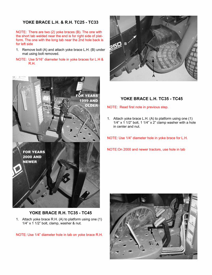
NOTE: Read first note in previous step.
1. Attach yoke brace L.H. (A) to platform using one (1) 1/4” x 1 1/2” bolt, 1 1/4” x 2” clamp washer with a hole in center and nut.
NOTE: Use 1/4” diameter hole in yoke brace for L.H.
NOTE:On 2000 and newer tractors, use hole in tab
YOKE BRACE L.H. TC35 - TC45
NOTE: There are two (2) yoke braces (B). The one with the short tab welded near the end is for right side of plat-form. The one with the long tab near the 2nd hole back is for left side
1. Remove bolt (A) and attach yoke brace L.H. (B) under mat using bolt removed.
NOTE: Use 5/16” diameter hole in yoke braces for L.H & R.H.
YOKE BRACE L.H. & R.H. TC25 - TC33
A
B
A
1. Attach yoke brace R.H. (A) to platform using one (1) 1/4” x 1 1/2” bolt, clamp, washer & nut.
NOTE: Use 1/4” diameter hole in tab on yoke brace R.H.
YOKE BRACE R.H. TC35 - TC45
A
FOR YEARS
2000 AND
NEWER
FOR YEARS
1999 AND
OLDER
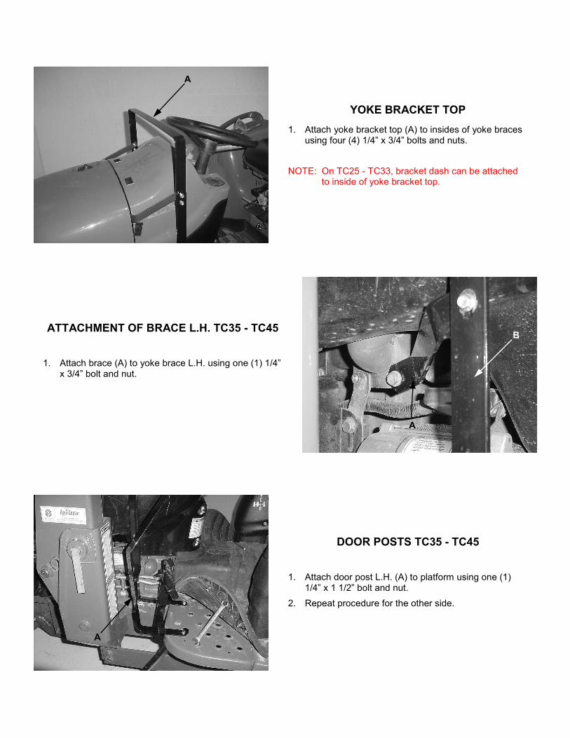
1. Attach yoke bracket top (A) to insides of yoke braces using four (4) 1/4” x 3/4” bolts and nuts.
NOTE: On TC25 - TC33, bracket dash can be attached to inside of yoke bracket top.
YOKE BRACKET TOP
1. Attach brace (A) to yoke brace L.H. using one (1) 1/4” x 3/4” bolt and nut.
ATTACHMENT OF BRACE L.H. TC35 - TC45
1. Attach door post L.H. (A) to platform using one (1) 1/4” x 1 1/2” bolt and nut.
2. Repeat procedure for the other side.
DOOR POSTS TC35 - TC45
A
B
A
A

1. Attach yoke brace tab (A) to top of yoke bracket top using two (2) 1/4” x 3/4” bolts and nuts.
NOTE: Holes 3/8” from edge will face up, holes 1/2” from edge will bolt to yoke bracket top.
YOKE BRACE TAB
1. Attach brace (A) to door post R.H. using one (1) 1/4” x 3/4” bolt and nut.
ATTACHMENT OF BRACE R.H. TC35 - TC45
1. Attach door post L.H. (A) to platform using one (1) 1/4” x 1 1/2” bolt and nut.
2. Repeat procedure for the other side.
DOOR POSTS TC25 - TC33
A
A
A

1. Attach yoke (A) to yoke brace tab using two (2) 1/4” x 3/4” bolts and nuts. Place bolt heads to front and nuts to rear of assembly.
2. Attach yoke ends to top of door posts using two (2) 1/4” X 1” bolts and nuts. Place bolt heads to rear and nuts front of assembly.
NOTE: This completes the frame work for all tractors. Some parts will have to be removed in later steps. Adjust door posts so they are straight up and down and tighten all bolts on the deck and braces at this time. DO NOT TIGHTEN THE YOKE bolts or DOOR POST BRACE.
YOKE
NOTE: On models that do not have side engine covers, install muffler guard as follows.
1. Remove bolts (A) and attach muffler guard (B) using same bolts removed.
2. Tighten Bolts.
MUFFLER GUARD TC25 - TC33
NOTE: Removal of patches on motor cover, if needed, is done by cutting every fourth thread and remove.
1. If loader is present, remove loader patches at bottom of motor cover. If there is a side exhaust, remove exhaust patch on left side of Motor Cover.
2. Remove yoke from frame work.
3. On TC35 - TC45, unbolt Brace R.H. from door post RH.
4. Slide 3” hem of motor cover (A) down over door posts and arrange motor cover to tractor. Slide yoke into top 3” hem and re-attach Yoke to door posts and Yoke Brace Tab.
5. On TC35 - TC45 only, locate hole where brace RH was located and cut holes in motor cover. Re-attach Brace RH and tighten.
MOTOR COVER
A
A
B
A

1. Remove 1/4” nuts from top of door posts.
2. Attach assembled windshield (A) using same nuts removed.
3. TIGHTEN ALL BOLTS.
WINDSHIELD ATTACHMENT
1. Attach left and right window frames using two (2) #10 x 1/2” bolts and nuts.
2. Slide glass into the channel of the windshield.
3. Attach flat strip and angle strip to the windshield using two (2) #10 x 1/2” bolts and nuts.
WINDSHIELD ASSEMBLY
1. Cut plastic Dual Lock into 2” lengths. 2. Surface must be cleaned with a mild detergent to as-
sure proper application of Velcro strips. NOTE: Do not peel the backing from the Dual Lock. 3. Apply cut Dual Lock to all Dual Lock sewn to motor
cover. 4. Arrange motor cover to tractor. Peel backing from
Dual Lock and apply to tractor. Repeat this procedure for all Dual Lock.
Dual Lock® a registered trademark of 3M Co.
A

IMPORTANT: Cloth straps are not to be attached to any moving, rotating, or heat generating points of the tractor. Any excess cloth straps are to be cut off.
1. Thread cloth strap through grommets at bottom of motor cover and tie.
2. Route cloth straps to other side or to a point on tractor and tie.
1. Locate holes in door post and punch holes in fabric.
2. Hold door (A) to door post and bottom of windshield.
3. Mark location of holes in door post to door.
4. Cut 5/8” slots next to wire frame of door, insert F-1 Clip around wire frame and attach to door posts using two (2) #10 x 3/4” bolts, and nuts.
5. Tie door flap to straps on motor cover.
6. Repeat procedure for the other side and tighten bolts.
DOORS
1. Mark location of holes in windshield to side window (A).
2. Cut 5/8” slots next to wire frame of window, insert F-1 Clip around wire frame and attach to windshield using two (2) #10 x 3/4” bolts and nuts.
3. At location (B), cut 5/8” slots inside window and door and attach using one (1) #10 x 3/4” bolt, F-1 Clip and nut.
4. Repeat procedure for the other side and tighten bolts.
SIDE WINDOWS
TIE STRAPS
A
A
B

1. Attach Latch (A) to Latch Lower (B) using two (2) 1/4” x 3/4” bolts and nuts.
2. Door is to rest in loop of Latch (A). Adjust door latch to door.
3. 1/4” flat washers can be used to level out door latch if desired.
4. Mark location for 9/32” diameter holes and drill fender.
5. Attach assembled door latch to fender using two (2) 1/4” x 1” bolts, fender washers and nuts.
6. Repeat procedure for the other side and TIGHTEN ALL BOLTS.
DOOR LATCH
A
B
NOTES