instructions for usethermotab.net/docs/tl1a-tl1wmanual.pdfeurope: atex code (ii 2 g) demko...
TRANSCRIPT
THE MANUAL DESCRIBES BASIC FUNCTION AND USE OF THERMOPROBE INSTRUMENTS AND BASIC SAFETY INSTRUCTIONS.The ThermoProbe Portable Electronic Thermometer is a portable digital temperature instrument. Intended use of ThermoProbe is both in hazardous (flammable) and non-hazardous areas. This portable instrument is intended for ATEX use for dry conditions (-20 to 40C). The instrument is not intended for use in permanent outdoor installationand is not intended or tested for use in icing conditions. Where the equipment may be exposed to excessive external stresses such as vibration, heat, and impact, theequipment must be protected.
© ThermoProbe, Inc. - Pearl, MS USA. All Rights Reserved. 1 2 / 2 0 09
ThermoProbe, Inc. 112-A Jetport Drive Pearl, MS 39208 USA www.thermoprobe.net Tel: +1 601.939.1831 Fax: +1 601.355.1831
USE OF INSTRUMENTThermoProbes are intended for operation in hazardous locations (PotentiallyFlammable or Explosive), the user must have a working knowledge of appropriatesafety instructions.
SEE MARKINGS ON INSTRUMENT AND READ THE FOLLOWING INSTRUCTIONS
PROCEDURES BEFORE USEa) The inspector must have a thorough knowledge of the products to be
measured and must know of the safety measures to be taken when workingwith the material to be measured.
b) Instrument shall be checked concerning severe defects; check thatinstrument is complete (where applicable grounding/bonding cable), hasgood batteries, etc. If necessary, check measurement accuracy. If any defectsare found, the instrument should not be used until repairs have been made.
c) Instrument, especially sensor (and cable), should be clean both for safetyreasons and ease of use.
d) Evaluation should be carried out to verify if physical place for measuring isconsidered a primary or secondary risk, or both.
FUNCTIONDepress the sealed "ON" button on the case to read measured temperature onthe display. The instrument will shut off within 20 minutes.
INTRINSIC SAFETYIntrinsically safe equipment is defined as "equipment and wiring which isincapable of releasing sufficient electrical or thermal energy under normal orabnormal conditions to cause ignition of a specific hazardous atmosphericmixture in its most easily ignited concentration." (ISA-RP12.6) This is achieved bylimiting the amount of power available to the electrical equipment in thehazardous area to a level below that which will ignite the gases.
In order to have a fire or explosion, fuel, oxygen and a source of ignition must bepresent. An intrinsically safe system assumes the fuel and oxygen is present inthe atmosphere, but the system is designed so the electrical energy or thermalenergy of a particular instrument loop can never be great enough to causeignition.
ADDITIONAL SAFETY INSTRUCTIONSa) Power source must be removed before performing any maintenance. b) Batteries must be changed in Non-hazardous area. Batteries must be of
correct type, see instrument identification plates on instrument.c) New batteries must not be mixed with old batteries; batteries must not be
mixed with batteries of other manufacturers.d) Exchange of components other than original components may compromise
the safety and is not recommended.
ESSENTIAL HEALTH AND SAFETY REQUIREMENTSThe equipment is designed to satisfy the requirements of Clause 1.2.7 of theEssential Health and Safety Requirements (European Standard).
GUIDANCE NOTEProblems with aggressive substances and environments: Be aware of aggressivesubstances and that extra protection may be needed. Exposure to Excessive heatcan melt the plastic components of the instrument.
TP-7, 8, 2C, 5C: Caustic soda, highly basic and acidic substances will erodealuminum and Copper ground clip and wire. The Sensor-Cable assembly hasexternal surfaces of stainless steel and fluoropolymer material.
TL-1A, W: The sensor has external surfaces of stainless steel, the sensor mountis acetal, the case is aluminum, gasket is silicone, and the switch-windowassembly is a vinyl compound.
STANDARDS SIGNIFICATIONThermoProbe instruments are classified as intrinsically safe to North American,European and Japanese standards. Depending on the particular instrument andregional requirements, certifications are provided by the following testing labora-tories: UL (US), DEMKO (Denmark) and TIIS (Japan). Please check instrumentidentification plates for necessary designation.
Safety ClassificationsNorth America: Class 1, Division I, Groups ABCD - Model TP-7, 8, 2C, 5CEurope: ATEX code (II 2 G) DEMKO 03ATEX133416XII 2G EExia IIB T3 Model TP-7, 8 with Duracell Battery II 2G EExia IIB T4 Model TP-7, 8 with Rayovac Battery II 2G EExia IIC T3 Model TP-7, 8 with Duracell Battery and special cableII 2G EExia IIC T4 Model TP-7, 8 with Rayovac Battery and special cableII 2G EExia IIB T4 Model TP-2C, 5C with Duracell MX2400 BatteryII 2G EExia IIC T4 Model TL-1A with Duracell DL2032 BatteryII 2G EExia IIC T4 Model TL-1W with Duracell MX2400 BatteryJapan: EExia IIB T4 Model TP-7, 8
Applicable Standards are: Agency or Safety Designation:UL 913 Intrinsic Safety US: UL LogoCSA 22.2 Intrinsic Safety Canada: ULc LogoCENELEC EN50014 Intrinsic Safety Europe: ATEX CE& Ex LogoCENELEC EN50020 Intrinsic Safety Europe: ATEX CE& Ex LogoCENELEC EN50081 EMC Emissions Europe: ATEX CE& Ex LogoCENELEC EN55022 EMC Immunity Europe: ATEX CE& Ex LogoJapan uses CENELEC Standards Japan: TIIS Only Text Designation
INSTRUCTIONS FOR USE

© ThermoProbe, Inc. - Pearl, MS USA. All Rights Reserved. 1 2 / 2 0 09
ThermoProbe, Inc. 112-A Jetport Drive. Pearl, MS 39208 USA www.thermoprobe.net Tel: +1 601.939.1831 Fax: +1 601.355.1831
FUNCTIONDepress the sealed "ON" button on the case to read measured temperature onthe display. The instrument will shut off within 20 minutes. Electronicstechnology allows hundreds of hours of use powered by a DL2032 coin cell in thecase of the TL-1A, and two MX2400 AAA cell batteries in the case of the TL-1W.
Arrows:The Arrows on the left side of the screen will show you at a glance as to whetherthe reading is increasing, decreasing or has stabilized. Intuitively the Up Arrowsymbolizes an increasing temperature, Down Arrow a decreasing temperatureand no arrows a stabilized status.
Low Battery:The instrument will display a warning "Lo BAtt" if the battery needs to bechanged.
TL-1A Auto-Off:The unit will turn off automatically in 20 minutes if no buttons are pressed.(Pressing "On/Off" button 4 seconds will disable the Auto-Off feature.)
TL-1W Backlight & Off:The unit is intended for extended or continuous operation and will remain on untilshut off. Pressing the On/Off button while operating will turn the backlight ontemporarily so the display can be read in dark conditions. To shut off theinstrument press and hold the On/Off button until the display goes blank.
On/Off button used to access the following operations:
» TL-1A Single press turns instrument On or Off» TL-1A Press for 4 seconds to disable Auto-Off feature» TL-1W Single press turns backlight On» TL-1W Press for 4 seconds to shut off instrument
Note: As soon as the unit is turned on, the minimum, maximum and average datais continuously updated. The data may be reset by momentarily shutting theinstrument off.
Function button used to access the following operations:
ERROR CODES:Two error codes have been established to provide the user informationconcerning the temperature sensor.» Err Lo - Short Circuit or Under Range» Err Hi - Open Circuit or Over Range"Err Lo" - When this happens, one of two situations exists. In normal operationthis represents a below range reading. The temperature being read is below themeasurable specified range. If the sensor is not exposed to temperatures belowthe specified operating range it is possible that the sensor or the connection tothe circuit board is short-circuited. Moisture on the circuit board may cause thiscondition.
"Err Hi" - Represents an over range reading, meaning the temperature at thesensor has risen above the measurable specified limit of the unit. Another possi-bility for this reading is a discontinuity in the sensor circuit. This may occur as aresult of a broken sensor wire at the circuit board or damaged sensor.
TL-1A, W REPLACING BATTERYa) Move into non-hazardous area.b) Remove the screws holding the back cover.c) For the TL-1A, use a small flat object move the plastic tab that is over the
edge of the battery. Once the tab is moved back the battery will lift upwardfor removal. Avoid bending the battery terminal. Note battery polarity beforeinserting a new battery into the holder. (+ Positive side faces top clip)
d) For the TL-1W push one battery towards the spring contact and lift batteryup from the holder, then remove the remaining battery. Mount each newbattery by aligning the (+) end of the battery with (+) embossed in the batterycase.
e) Reinstall the cover plate.
TL-1A, W CALIBRATION PROCEDUREAn authorized ThermoProbe distributor or service facility should performcalibration.
TL-1A, W REPAIRS & MAINTENANCEThis instrument has no user serviceable parts and must be sent to an authorizedrepair agent or directly to ThermoProbe Inc. for calibration or repair.
TL-1A, TL-1W OPERATION
f
USER OPERATION FUNCTION (F) ANNUNCIATOR
One quick pushLowest Reading (min), Average ReadingHighest Reading (max)
"L""A""H"
Hold and Release whendisplay reads "C-F" °F <-> °C "C-F"
Hold and Release whendisplay reads "dEc" 0.X <-> 0.XX "dEc"
LE MANUEL DÉCRIT LES FONCTIONS DE BASE, L'UTILISATION DES INSTRUMENTS THERMOPROBE ET LES INSTRUCTIONS DE SÉCURITÉ FONDAMENTALES. Le thermomètre électronique portable ThermoProbe est un instrument de température portatif. ThermoProbe s'utilise autant dans les zones dangereuses (inflammables) quenon dangereuses. Cet instrument portatif est envisagé pour l'utilisation ATEX dans des conditions sèches (-20 à 40C). L'instrument n'est pas projeté pour l'utilisation dansune installation permanente à l'extérieur ou contrôlé pour l'utilisation en conditions de givrage. Il faut protéger l'équipement s'il risque d'être exposé à des stress externesexcessifs comme la vibration, la chaleur, et l'impact.
© ThermoProbe, Inc. - Pearl, MS USA. All Rights Reserved. 1 2 / 2 0 09
ThermoProbe, Inc. 112-A Jetport Drive Pearl, MS 39208 USA www.thermoprobe.net Tel: +1 601.939.1831 Fax: +1 601.355.1831
UTILISATION DE L'INSTRUMENTLes ThermoProbes sont conçus pour être utilisés dans des endroits dangereux(susceptibles de présenter un danger d'incendie ou d'explosion), et l'utilisateurdoit avoir une connaissance pratique des instructions de sécurité appropriées.
VOIR LES MARQUAGES SUR L'INSTRUMENT ET VEUILLEZ LIRE LESINSTRUCTIONS SUIVANTES
PROCÉDURES AVANT L'UTILISATIONa) L'inspecteur doit avoir une connaissance approfondie des produits à jauger et
connaître les mesures de sécurité à prendre en travaillant avec le matériel àmesurer.
b) Il faut vérifier si l'instrument comporte des défauts ; assurez-vous qu'il soitcomplet (et, le cas échéant, le câble de liaison/mise à la terre), qu'il ait debonnes batteries, etc. Vérifiez, si nécessaire, la précision de la mesure. En casde présence de défauts, n'utilisez pas l'instrument avant qu'il ne soit réparé.
c) Il faut nettoyer l'instrument, spécialement le capteur (et le câble) pour desraisons de sécurité et de facilité d'usage.
d) Il faut effectuer l'évaluation pour vérifier si la place physique pour sonder estconsidérée à risque primaire ou secondaire, ou les deux.
FONCTIONAppuyez sur le bouton scellé "ON" sur le boîtier pour lire la température mesuréesur l'écran d'affichage. L'instrument se ferme dans un délai de 20 minutes.
SÉCURITÉ INTRINSÈQUEL'instrument à sécurité intrinsèque se définit comme un "équipement et uncâblage incapable de relâcher une énergie électrique ou thermique suffisante enconditions normales ou anormales pour causer l'allumage d'un mélangeatmosphérique dangereux dans sa concentration le plus facilement inflammable."(ISA-RP12.6) Ceci est réalisable en limitant le montant de puissance disponiblevers l'équipement électrique dans la zone dangereuse à un niveau en dessous decelui qui enflammera les gaz.
Pour qu'il y ait une explosion ou un incendie, il faut qu'il y ait présence de carburant,d'oxygène et d'une source d'allumage. Un système intrinsèque sûr prend pour acquisla présence de l'oxygène et du carburant dans l'atmosphère, mais le système estconçu de façon à ce que l'énergie électrique ou thermique d'une boucle particulièrede l'instrument ne soit jamais assez grande pour causer l'allumage.
INSTRUCTIONS DE SÉCURITÉ SUPPLÉMENTAIRESa) Il faut enlever le bloc d'alimentation avant d'effectuer toute forme d'entretien. b) Il faut changer les batteries dans des zones non dangereuses. Les batteries
doivent être du bon type, voir les plaques signalétiques sur l'instrumentc) Il ne faut pas mêler les batteries neuves avec les vieilles batteries ; il ne faut
pas les mélanger avec les batteries des autres fabricants. d) L'échange de composants autres que les composants originaux pourrait
compromettre la sécurité et n'est pas recommandé.
EXIGENCES ESSENTIELLES DE SANTÉ ET DE SÉCURITÉL'instrument est conçu pour satisfaire les exigences de la clause 1.2.7 desExigences essentielles de santé et de sécurité (Normes européennes).
NOTES D'ORIENTATIONProblèmes avec les substances fortes et les environnements : Attention auxsubstances fortes : une ultérieure protection pourrait s'avérer nécessaire. Uneexposition à la chaleur excessive pourrait faire fondre les composants enplastique de l'instrument.
TP-7, 8, 2C, 5C: L'hydroxyde de sodium et les substances très acides érodent l'alu-minium ainsi que le fil et le collier de mise à la terre en aluminium. Les surfacesexternes du faisceau de câble du capteur sont en acier inoxydable et polymèrefluoré.
TL-1A, W: Les surfaces externes du capteur sont en acier inoxydable, la monturedu capteur est en acétal, le boîtier en aluminium et l'assemblage de changementde fenêtre est un composé en vinyle.
SIGNIFICATION DES NORMESLes instruments ThermoProbe respectent la sécurité intrinsèque des normeseuropéennes, japonaises et d'Amérique du Nord. Les certifications, selon laparticularité de l'instrument et les exigences régionales, sont fournies par leslaboratoires d'essai suivants : UL (É.-U.), DEMKO (Danemark) et TIIS (Japon).Veuillez vérifier les plaques signalétiques de l'instrument pour le marquage desécurité.
Classifications en matière de sécurité Amérique du Nord : Classe 1, Division I, Groupes ABCD - Modèle TP-7, 8, 2C, 5CEurope: Code ATEX (II 2 G) DEMKO 03ATEX133416XII 2G EExia IIB T3 Modèle TP-7, 8 avec batterie Duracell II 2G EExia IIB T4 Modèle TP-7, 8 avec batterie Rayovac II 2G EExia IIC T3 Modèle TP-7, 8 avec batterie Duracell et câble spécial II 2G EExia IIC T4 Modèle TP-7, 8 avec batterie Duracell et câble spécial II 2G EExia IIB T4 Modèle TP-2C, 5C avec batterie Duracell MX2400 II 2G EExia IIC T4 Modèle TL-1A avec batterie Duracell DL2032 II 2G EExia IIC T4 Modèle TL-1W, 5C avec batterie Duracell MX2400 Japon: EExia IIB T4 Modèle TP-7, 8
Les normes applicables sont: Marquage de sécurité ou de l'agence:Sécurité intrinsèque UL 913 É.-U. Logo ULSécurité intrinsèque CSA 22,2 Canada: Logo ULcSécurité intrinsèque CENELEC EN50014 Europe: ATEX CE& Ex LogoSécurité intrinsèque CENELEC EN50020 Europe: ATEX CE& Ex LogoCENELEC EN50081 EMC Emissions
de compatibilité électromagnétique Europe: ATEX CE& Ex LogoCENELEC EN55022 Immunité
de comptabilité électromagnétique Europe: ATEX CE& Ex LogoLe Japon utilise les normes CENELEC Japon: TIIS Désignation texte seulement
INSTRUCTIONS POUR L'UTILISATION
FONCTIONAppuyez sur le bouton scellé "ON" sur le boîtier pour lire la température mesuréesur l'écran d'affichage. L'instrument se ferme dans un délai de 20 minutes. Latechnologie électronique permet des centaines d'heures d'utilisation alimentéespar une pile coin cell DL2032 dans le cas du TL-1A, et deux éléments de pileMX2400 AAA dans le cas du TL-1W.
Flèches :Les flèches sur le côté gauche de l'écran vous montrent d'un coup d'œil si lalecture augmente, diminue ou s'est stabilisée. D'une manière intuitive, Up Arrow(Flèche vers le haut) symbolise l'augmentation de la température, Down Arrow(Flèche vers le haut) symbolise la diminution de la température et aucune flècheun état de stabilisation.
Batterie basse:L'instrument affiche un avertissement "Lo BAtt" si la batterie doit être changée.
Arrêt automatique du TL-1A:Le groupe se ferme automatiquement après 20 minutes si aucun bouton n'estappuyé. (En appuyant sur le bouton marche - arrêt ("On/Off") pendant 4secondes, le dispositif d'arrêt automatique se désactive)
Activation et désactivation du panneau lumineux TL-1W:L'appareil est conçu pour un fonctionnement continu ou étendu et reste ouvertjusqu'à ce qu'il soit éteint. En appuyant sur le bouton arrêt/marche (On/Off) lepanneau lumineux s'allume temporairement pour lire l'écran d'affichage dansdes conditions d'obscurité. Pour fermer l'instrument appuyer et tenir le boutonmarche -arrêt (On/Off) jusqu'à ce que l'affichage devienne noir.
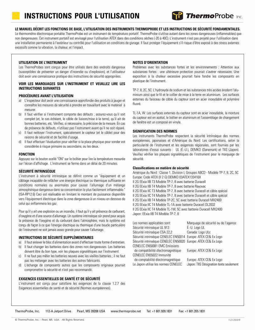
Le 'On button' (bouton marche) utilisé pour accéder aux opérations suivantes
» En appuyant une fois sur le TL-1A l'instrument s'allume ous'éteint.
» En appuyant sur le TL-1A pendant 4 secondes le dispositifd'arrêt automatique se désactive
» En appuyant une fois sur le TL-1W le panneau lumineuxs'allume
» En appuyant sur le TL-1W pendant 4 secondesl'instrument se ferme.
Remarque: Dès que l'appareil est allumé, les données minimum, maximum etleur moyenne sont continuellement mises à jour. Il est possible de réinitialisermomentanément les données en fermant l'instrument.
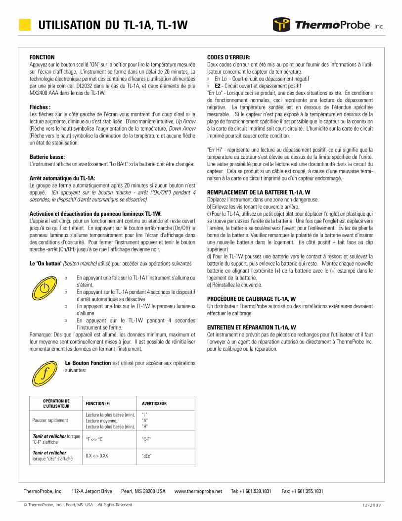
Le Bouton Fonction est utilisé pour accéder aux opérationssuivantes:
CODES D'ERREUR:Deux codes d'erreur ont été mis au point pour fournir des informations à l'util-isateur concernant le capteur de température.» Err Lo - Court-circuit ou dépassement négatif » E2 - Circuit ouvert et dépassement positif "Err Lo" - Lorsque ceci se produit, une des deux situations existe. En conditionsde fonctionnement normales, ceci représente une lecture de dépassementnégative. La température sondée est en dessous de l'étendue spécifiéemesurable. Si le capteur n'est pas exposé à la température en dessous de laplage de fonctionnement spécifiée il est possible que le capteur ou la connexionà la carte de circuit imprimé soit court-circuité. L'humidité sur la carte de circuitimprimé pourrait causer cette condition.
"Err Hi" - représente une lecture au dépassement positif, ce qui signifie que latempérature au capteur s'est élevée au dessus de la limite spécifiée de l'unité.Une autre possibilité pour cette lecture est une discontinuité dans le circuit ducapteur. Cela se produit si un câble est coupé, à cause d'une mauvaise termi-naison à la carte de circuit imprimé ou d'un capteur endommagé.
REMPLACEMENT DE LA BATTERIE TL-1A, W Déplacez l'instrument dans une zone non dangereuse.b) Enlevez les vis tenant le couvercle arrière.c) Pour le TL-1A, utilisez un petit objet plat pour déplacer l'onglet en plastique quise trouve par dessus l'arête de la batterie. Une fois que l'onglet est déplacé versl'arrière, la batterie se soulève vers l'avant pour l'enlèvement. Évitez de plier laborne de la batterie. Veuillez remarquer la polarité de la batterie avant d'insérerune nouvelle batterie dans le logement. (le côté positif + fait face au clipsupérieur)d) Pour le TL-1W poussez une batterie vers le contact à ressort et soulevez labatterie du support, puis enlevez la batterie qui reste. Montez chaque nouvellebatterie en alignant l'extrémité (+) de la batterie avec le (+) estampé dans lelogement de la batterie. e) Réinstallez le couvercle.
PROCÉDURE DE CALIBRAGE TL-1A, WUn distributeur ThermoProbe autorisé ou des installations extérieures devraienteffectuer le calibrage.
ENTRETIEN ET RÉPARATION TL-1A, W Cet instrument ne prévoit pas de pièces de rechanges pour l'utilisateur et il fautl'envoyer à un agent de réparation autorisé ou directement à ThermoProbe Inc.pour le calibrage ou la réparation.
© ThermoProbe, Inc. - Pearl, MS USA. All Rights Reserved. 1 2 / 2 0 09
ThermoProbe, Inc. 112-A Jetport Drive Pearl, MS 39208 USA www.thermoprobe.net Tel: +1 601.939.1831 Fax: +1 601.355.1831
UTILISATION DU TL-1A, TL-1W
f
OPÉRATION DEL'UTILISATEUR FONCTION (F) AVERTISSEUR
Pousser rapidementLecture la plus basse (min), Lecture moyenne,Lecture la plus basse (min),
"L""A""H"
Tenir et relâcher lorsque"C-F" s'affiche °F <-> °C "C-F"
Tenir et relâcherlorsque "dEc" s'affiche 0.X <-> 0.XX "dEc"

DAS HANDBUCH BESCHREIBT DIE GRUNDFUNKTIONEN UND DIE VERWENDUNG DER THERMOPROBE-INSTRUMENTE SOWIE GRUNDLEGENDESICHERHEITSANWEISUNGEN. Das portable elektronische ThermoProbe-Thermometer ist ein portabler digitaler Temperaturmesser. Der Verwendungszweck desThermoProbe-Geräts liegt sowohl im gefährlichen (entflammbaren) als auch ungefährlichen Bereich. Dieses tragbare Instrument kann für ATEX-Zwecke bei trockenenBedingungen (-20 to 40C) eingesetzt werden. Das Instrument ist nicht für den dauerhaften Einsatz draußen gedacht und ist bestimmt oder wurde gestestet für denEinsatz bei eisigen Bedingungen. Wenn das Gerät übermäßiger äußerer Beanspruchung wie etwa Erschütterungen, Hitze und Stoßwirkung ausgesetzt ist, muss dasGerät geschützt werden.
© ThermoProbe, Inc. - Pearl, MS USA. All Rights Reserved. 1 2 / 2 0 09
ThermoProbe, Inc. 112-A Jetport Drive Pearl, MS 39208 USA www.thermoprobe.net Tel: +1 601.939.1831 Fax: +1 601.355.1831
NUTZUNG DES INSTRUMENTSThermoProbe-Instrumente sind zum Betrieb an gefährlichen Orten (potentiellentflammbar oder explosiv) geeignet. Der Benutzer muss ausreichendeKenntnisse geeigneter Sicherheitsvorschriften haben.
SEHEN SIE SICH DIE MARKIERUNGEN AUF DEM INSTRUMENT AN,UND LESEN SIE DIE FOLGENDEN ANWEISUNGEN
VORGEHEN VOR DEM GEBRAUCHa) Der Prüfer muss gründliche Kenntnisse der zu messenden Produkte haben undmuss die zu ergreifenden Sicherheitsmaßnahmen kennen, wenn das zumessende Material bearbeitet wird.b) Das Instrument muss auf schwere Mängel untersucht werden; es mussüberprüft werden, ob das Instrument vollständig ist (wo zutreffend Erdungs-/Verbindungskabel), ob die Batterien voll sind, usw. Falls erforderlich, dieMessgenauigkeit prüfen. Werden Mängel gefunden, sollte das Instrument nichtgenutzt werden, bis eine Reparatur vorgenommen wurde.c) Das Instrument, insbesondere Sensor (und Kabel) sollten ausSicherheitsgründen und zur einfachen Handhabung sauber sein.d) Es sollte eine Bewertung vorgenommen werden, damit geprüft werden kann,ob der physische Ort der Messung als primäres oder sekundäres Risiko oderbeides eingestuft wird.
FUNKTIONSWEISEDen abgedichteten Knopf "ON" auf dem Gehäuse herunterdrücken, damit diegemessene Temperatur auf der Anzeige abgelesen werden kann. Das Instrumentstellt sich nach 20 Minuten ab.
INHÄRENTE SICHERHEITInhärent sichere Ausrüstung wird definiert als "Gerätschaften und Verkabelung,die in dazu in der Lage sind, ausreichend elektrische oder Wärmeenergie unternormalen oder anormalen Bedingungen abzugeben, um eine Entzündung einerspezifisch gefährlichen atmosphärischen Mischung in der am leichtestenentzündbaren Konzentration hervorzurufen." (ISA-RP12.6) Dies wird durchBegrenzung der der elektrischen Ausrüstung zur Verfügung Energiemenge in dergefährlichen Umgebung auf ein Niveau erreicht, das Gase entzündet.
Zur Entfachung eines Feuers oder Herbeiführung einer Explosion müssenBrennstoff, Sauerstoff und eine Zündquelle vorhanden sein. Ein inhärent sicheresSystem setzt voraus, dass Brennstoff und Sauerstoff in der Atmosphärevorhanden sind, aber das System ist derart konzipiert, dass die elektrischeEnergie der Wärmeenergie einer bestimmten Instrumentenschleife nie hochgenug ist, um eine Entzündung auszulösen.
ZUSÄTZLICHE SICHERHEITSANWEISUNGENa) Die Energiequelle muss vor dem Durchführen einer Wartung entfernt werden. b) Batterien müssen in ungefährlichen Bereichen ausgewechselt werden.
Batterien müssen den richtigen Typ haben; siehe Kennzeichnungen auf demInstrument.
c) Neue Batterien dürfen nicht mit alten gemischt werden; Batterien dürfennicht mit Batterien anderer Hersteller gemischt werden.
d) Der Austausch von Komponenten, die keine Originalkomponenten sind,können die Sicherheit gefährden und werden nicht empfohlen.
GRUNDLEGENDE GESUNDHEITS- UND SICHERHEITSANFORDERUNGENDas Gerät ist so konzipiert, dass es den Anforderungen des Paragraphen 1.2.7der Grundlegenden Gesundheits- und Sicherheitsanforderungen (europäischerStandard) entspricht.
RICHTLINIENProbleme mit aggressiven Substanzen und Umgebungen: Achten Sie aufaggressive Substanzen und darauf, dass eventuell zusätzlicher Schutzerforderlich ist. Wird das Instrument extremer Hitze ausgesetzt, können seinePlastikkomponenten schmelzen.
TP-7, 8, 2C, 5C: Natronlauge, hoch basische und säurehaltige Substanzen erodierenAluminium- sowie Kupferklemmen und -kabel. Die Sensorkabelbaugruppe hatäußere Oberflächen aus Edelstahl und Fluorpolymeren.
TL-1A, W: Der Sensor hat äußere Oberflächen aus Edelstahl, die Sensorhalterungist aus Acetal, das Gehäuse aus Aluminium, die Dichtung aus Silikon, und dasSchalterfenster ist eine Vinylverbindung.
BEDEUTUNG DER STANDARDSThermoProbe-Instrumente sind als inhärent sicher gemäß der nordamerikanischen,europäischen und japanischen klassifiziert. Abhängig vom jeweiligen Instrumentund regionalen Anforderungen werden von den folgenden Testlabors Zertifikateausgestellt: UL (USA), DEMKO (Dänemark) und TIIS (Japan). Bitte überprüfen Siedie Instrumentenkennzeichnungen auf erforderliche Angaben.
SicherheitsklassifizierungenNordamerika: Klasse 1, Division I, Gruppen ABCD - Modell TP-7, 8, 2C, 5CEuropa: ATEX-Code (II 2 G) DEMKO 03ATEX133416XII 2G EExia IIB T3 Modell TP-7, 8 mit Duracell-Batterie II 2G EExia IIB T4 Modell TP-7, 8 mit Rayovac-Batterie II 2G EExia IIC T3 Modell TP-7, 8 mit Duracell-Batterie und speziellem KabelII 2G EExia IIC T4 Modell TP-7, 8 mit Rayovac-Batterie und speziellem KabelII 2G EExia IIB T4 Modell TP-2C, 5C mit Duracell MX2400 BatterieII 2G EExia IIC T4 Modell TL-1A mit Duracell DL2032 BatterieII 2G EExia IIC T4 Modell TL-1W mit Duracell MX2400 BatterieJapan: EExia IIB T4 Modell TP-7, 8
Anwendbare Standards: Agentur oder SicherheitsangabenUL 913 Intrinsic Safety USA: UL LogoCSA 22.2 Intrinsic Safety Kanada: ULc LogoCENELEC EN50014 Intrinsic Safety Europa: ATEX CE& Ex LogoCENELEC EN50020 Intrinsic Safety Europa: ATEX CE& Ex LogoCENELEC EN50081 EMC Emissions Europa: ATEX CE& Ex LogoCENELEC EN55022 EMC Immunity Europa: ATEX CE& Ex LogoJapan verwendet CENELEC-Standards Japan: Nur TIIS-Textangaben
BEDIENUNGSANLEITUNG

© ThermoProbe, Inc. - Pearl, MS USA. All Rights Reserved. 1 2 / 2 0 09
ThermoProbe, Inc. 112-A Jetport Drive Pearl, MS 39208 USA www.thermoprobe.net Tel: +1 601.939.1831 Fax: +1 601.355.1831
FUNKTIONSWEISEDen abgedichteten Knopf "ON" auf dem Gehäuse herunterdrücken, damit diegemessene Temperatur auf der Anzeige abgelesen werden kann. Das Instrumentstellt sich nach 20 Minuten ab. Die Elektrotechnik ermöglicht hunderteBetriebsstunden mit einer DL2032 Knopfzelle bei einem TL-1A und zwei MX2400AAA Zellenbatterien bei einem TL-1W.
Pfeile:Die Pfeile auf der linken Seite des Bildschirms zeigen Ihnen auf einen Blick, obdie Ablesung steigt, sinkt oder sich stabilisiert hat. Der Pfeil nach oben zeigtintuitiv steigende Temperatur an, der Pfeil nach unten eine sinkende Temperaturund keine Pfeile einen stabilisierten Status.
Schwache Batterie:Das Instrument zeigt eine Warnung "Lo Batt" an, wenn die Batterie gewechseltwerden muss.
TL-1A Automatische Abschaltung:Das Gerät stellt sich nach 20 Minuten automatisch ab, wenn keine Knöpfegedrückt werden. (4 Sekunden langes Drücken des Knopfes "On/Off" stellt dieautomatische Abschaltung aus.)
TL-1W Beleuchtung und Abschaltung:Das Gerät dient eines längerfristigen oder dauerhaften Betrieb und bleibtangeschaltet, bis das gerät ausgeschaltet wird. Das Drücken des Knopfes On/Offwährend des Betriebs schaltet die Beleuchtung zeitweise ein, so dass dasDisplay bei Dunkelheit abgelesen werden kann. Zum Ausschalten desInstruments drücken und halten Sie den Knopf On/Off, bis das Display erlischt.
Der Knopf On/Off wird dazu genutzt, auf folgende Funktionen zuzugreifen:
» TL-1A Einmal drücken schaltet das Instrument ein oder aus» TL-1A 4 Sekunden langes Drücken schaltet das automatische
Abschalten aus» TL-1W Einmal drücken schaltet die Beleuchtung ein» TL-1W 4 Sekunden langes Drücken schaltet das Instrument aus
Hinweis: Sobald das Gerät eingeschaltet ist, werden die minimalen, maximalenund durchschnittlichen Daten fortwährend aktualisiert. Die Daten können durchvorübergehendes Ausschalten des Instruments zurückgesetzt werden.
Der Knopf Function wird dazu genutzt, auf folgendeFunktionen zuzugreifen:
FEHLERCODES:Es wurden zwei Fehlercodes eingeführt, die dem Benutzer Informationen zumTemperatursensor geben.» Err Lo - Kurzschluss oder Unter dem Bereich» Err Hi - Offener Schaltkreis oder Über dem Bereich"Err Lo" zeigt an, das eine der beiden Situationen eingetreten ist. Bei normalemBetrieb stellt das eine Ablesung unter dem Bereich dar. Die abgeleseneTemperatur befindet sich unter dem angegebenen messbaren Bereich. Ist derSensor keinen Temperaturen unter dem angegebenen Betriebsbereich ausge-setzt, bedeutet dies, dass der Sensor oder die Verbindung zur Anschlussplatineeinen Kurzschluss hat. Feuchtigkeit auf der Anschlussplatine kann dazu führen.
"Err Hi" stellt eine Ablesung oberhalb des Bereichs dar, was bedeutet, dass dieTemperatur am Sensor über den angegebenen messbaren Bereich des Gerätshinaus gestiegen ist. Eine andere Möglichkeit ist eine Unterbrechung imSensorschaltkreis. Das kann passieren, wenn ein Sensorkabel an derAnschlussplatine zerstört oder der Sensor beschädigt ist.
TL-1A, W BATTERIE AUSWECHSELNa) Begeben Sie sich in nicht gefährliches Gebiet.b) Entfernen Sie die Schrauben an der hinteren Abdeckung.c) verwenden Sie für den TL-1A ein kleines flaches Objekt, um die Plastikklappeüber dem Rand der Batterie zu entfernen. Nach dem Entfernen der Klappe kommtdie Batterie zum Entnehmen nach oben. Vermeiden Sie Verbiegen desBatterieendes. Merken Sie sich die Batteriepolarität vor dem Einlegen einerneuen Batterie in die Halterung. (+ Positive Seite zur oberen klemme hin)d) Beim TL-1W schieben Sie eine Batterie in Richtung des Federkontakts undnehmen Sie die Batterie aus der Halterung, dann entfernen Sie die andereBatterie. Legen Sie die neuen Batterien so ein, dass das (+) Ende der Batterie aufdas eingeprägte (+) im Batteriefach ausgerichtet ist. e) Legen Sie die Abdeckung wieder ein.
TL-1A, W KALIBRIERUNGSVORGANGEin autorisierter ThermoProbe-Vertriebshändler oder -Dienstleistungsbetriebsollten die Kalibrierung vornehmen.
TL-1A, W REPARATUREN UND WARTUNGDieses Instrument hat keine für den Benutzer wartbaren Teile und muss an einenautorisierten Reparaturdienst oder direkt an ThermoProbe Inc. zur Kalibrierungoder Reparatur geschickt werden.
TL-1A, TL-1W BEDIENUNG
fBETÄTIGUNG DURCH DENBENUTZER FUNKTION (f) MELDUNG
Ein schnelles DrückenNiedrigste Ablesung (min), Durchschnittliche AblesungHöchste Ablesung (max)
"L""A""H"
Halten und loslassen, wenndas Display "C-F" anzeigt
°F <-> °C "C-F"
Halten und loslassen, wenndas Display "dEc" anzeigt
0.X <-> 0.XX "dEc"

РУКОВОДСТВО ОПИСЫВАЕТ ОСНОВНЫЕ ФУНКЦИИ И ИСПОЛЬЗОВАНИЕ ИНСТРУМЕНТОВ, ВЫПУСКАЕМЫХ КОМПАНИЕЙ THERMOPROBE, И СОДЕРЖИТ ОСНОВНЫЕ ИНСТРУКЦИИ ПО ТЕХНИКЕ БЕЗОПАСНОСТИ. ПОРТАТИВНЫЙ ЭЛЕКТРОННЫЙ ТЕРМОМЕТР КОМПАНИИ THERMOPROBE – ЭТО ПЕРЕНОСНОЙ ЦИФРОВОЙ ИНСТРУМЕНТ ДЛЯ ИЗМЕРЕНИЯ ТЕМПЕРАТУРЫ. ПРЕДНАЗНАЧЕННОЕ ИСПОЛЬЗОВАНИЕ ИНСТРУМЕНТОВ КОМПАНИИ THERMOPROBE ВОЗМОЖНО КАК В ОПАСНЫХ (ОГНЕОПАСНЫХ), ТАК И В НЕОПАСНЫХ УСЛОВИЯХ. ЭТОТ ПОРТАТИВНЫЙ ИНСТРУМЕНТ ПРЕДНАЗНАЧЕН ДЛЯ ПРИМЕНЕНИЯ ВО ВЗРЫВООПАСНОЙ АТМОСФЕРЕ (ПО НОРМАМ ATEX) В СУХУЮ ПОГОДУ (ОТ -20 ДО 40 ГРАД. C). ПРИБОР НЕ ПРЕДНАЗНАЧЕН ДЛЯ ПОСТОЯННОГО ПРИМЕНЕНИЯ В НАРУЖНЫХ УСЛОВИЯХ И НЕ ПРЕДНАЗНАЧЕН ИЛИ НЕ БЫЛ ПРОВЕРЕН НА ИСПОЛЬЗОВАНИЕ ПРИ МОРОЗЕ. КОГДА ОБОРУДОВАНИЕ МОЖЕТ БЫТЬ ПОДВЕРГНУТО ЧРЕЗМЕРНЫМ ВНЕШНИМ ВОЗДЕЙСТВИЯМ ТИПА ВИБРАЦИИ, НАГРЕВА И УДАРОВ, ОБОРУДОВАНИЕ ДОЛЖНО БЫТЬ ЗАЩИЩЕНО.
© ThermoProbe, Inc. - Pearl, MS USA. All Rights Reserved. 12/2009
ThermoProbe, Inc. 112-A Jetport Drive Pearl, MS 39208 USA www.thermoprobe.net Tel: +1 601.939.1831 Fax: +1 601.355.1831
ИСПОЛЬЗОВАНИЕ ИНСТРУМЕНТАИнструменты компании ThermoProbe предназначены для работы в опасных местах (потенциально огнеопасных или взрывоопасных), пользователь должен иметь рабочее знание соответствующих правил техники безопасности.
СМ. МАРКИРОВКИ НА ИНСТРУМЕНТЕ И ЧИТАЙТЕ СЛЕДУЮЩИЕ ИНСТРУКЦИИ
ПРОЦЕДУРЫ ПЕРЕД ИСПОЛЬЗОВАНИЕМa) Инспектор должен иметь всестороннее знание изделий, которые будут измерены и должен знать о мерах по обеспечению безопасности, которые следует предпринять при работе с материалом, на котором будет проводиться измерение.b) Инструмент должен быть проверен на наличие серьезных дефектов; проверьте комплектацию инструмента (наличие необходимого кабеля заземления/соединения), наличие хороших батарей и т.д. Если необходимо, проверьте точность измерения. Если обнаружены любые дефекты, инструмент не должен использоваться, пока не будет сделан ремонт.c) Инструмент, особенно датчик (и кабель), должен быть чист как по соображениям безопасности, так и удобства использования.d) Должна быть выполнена оценка того, что для физического места для измерения характерен первичный или вторичный риск, или оба.
ФУНКЦИОНИРОВАНИЕНажмите защищенную кнопку «ON” (Вкл.) на корпусе, чтобы прочитать на дисплее измеренную температуру. Прибор отключится в течение 20 минут.
ВЗРЫВОБЕЗОПАСНОСТЬВзрывобезопасное оборудование определяется как «оборудование и проводка, которые являются неспособными к выпуску достаточной электрической или тепловой энергии при нормальных или аварийных условиях, чтобы вызвать воспламенение определенной опасной атмосферной смеси при ее наиболее легко воспламеняемой концентрации” (ISA-RP12.6). Это достигается ограничением количества электроэнергии, доступной электрооборудованию в опасной области, ниже того уровня, который воспламеняет газы.
Чтобы получить огонь или взрыв, должны присутствовать топливо, кислород и источник воспламенения. Система взрывобезопасности учитывает то, что топливо и кислород присутствуют в атмосфере, но система разработана так, что электроэнергия или тепловая энергия в специфической цепи инструмента никогда не может быть достаточно большой, чтобы вызвать воспламенение.
ДОПОЛНИТЕЛЬНЫЕ ИНСТРУКЦИИ ПО МЕРАМ БЕЗОПАСНОСТИ a) Источник питания должен быть удален перед выполнением любого
обслуживания. b) Замена батарей должна производиться в безопасной зоне. Батареи
должны иметь правильного типа, в соответствии с указанием на этикетке инструмента.
c) Нельзя смешивать новые батареи со старыми батареями; не следует смешивать батареи различных изготовителей.
d) Замена компонентов на отличающиеся от оригинальных компонентов может снизить безопасность и не рекомендуется.
ОСНОВНЫЕ ТРЕБОВАНИЯ ДЛЯ ОБЕСПЕЧЕНИЯ ЗДОРОВЬЯ И БЕЗОПАСНОСТИ Оборудование разработано в соответствии с положениями Пункта 1.2.7 Основных требований для обеспечения здоровья и безопасности (Европейский стандарт).
ПРИМЕЧАНИЕ ПО ПРИМЕНЕНИЮ Проблемы при наличии агрессивных веществ и окружающих сред: учитывайте, что при наличии агрессивных веществ может быть необходима дополнительная защита. Воздействие чрезмерно высокой температуры может расплавить пластмассовые детали инструмента.
TP-7, 8, 2C, 5C: Каустическая сода, вещества с высоким содержанием щелочей и кислот вызовут эрозию алюминиевых и медных клемм заземления и провода. Сборка датчик-кабель имеет внешние поверхности из нержавеющей стали и фторополимерного материала.
TL-1A, W: Датчик кабель имеет внешние поверхности из нержавеющей стали, крепление дачика из ацетала, корпус из алюминия, уплотнение из силикона и сборка выключателя-окошка из винилового компаунда.
СООТВЕТСТВИЕ НОРМАМИнструменты компании ThermoProbe классифицируются как взрывобезопасные согласно стандартам Северной Америки, Европы и Японии. В зависимости от специфических инструментальных и региональных требований, сертификации были выданы следующими испытательными лабораториями: UL (США), DEMKO (Дания) и TIIS (Япония). Необходимые обозначения можно найти на табличках с паспортными данными.
Классификация по соответствию нормам безопасности:Северная Америка: Класс 1, Раздел I, Группы ABCD - Модель TP-7, 8, 2C, 5CЕвропа: Нормы ATEX (II 2 G) DEMKO 03ATEX133416XII 2G EExia IIB T3 Модель TP-7, 8 с батарейкой Duracell II 2G EExia IIB T4 Модель TP-7, 8 с батарейкой Rayovac II 2G EExia IIC T3 Модель TP-7, 8 с батарейкой Duracell и специальным кабелемII 2G EExia IIC T4 Модель TP-7, 8 с батарейкой Rayovac Battery и специальным кабелемII 2G EExia IIB T4 Модель TP-2C, 5C с батарейкой Duracell MX2400 II 2G EExia IIC T4 Модель TL-1A с батарейкой Duracell DL2032 II 2G EExia IIC T4 Модель TL-1W с батарейкой Duracell MX2400 Япония: EExia IIB T4 Модель TP-7, 8
Применимые нормы: Учреждение или знак для норм безопасности:Взрывобезопасность UL 913 США: логограмма UL Взрывобезопасность CSA 22.2 Канада: логограмма ULc Взрывобезопасность CENELEC EN50014 Европа: логограмма ATEX CE& Ex Взрывобезопасность CENELEC EN50020 Европа: логограмма ATEX CE& Ex CENELEC EN50081 ЭМС-излучения Европа: логограмма ATEX CE& Ex CENELEC EN55022 ЭМС-невосприимчивость Европа: логограмма ATEX CE& Ex Япония использует нормы CENELEC Япония: только текстовое указание TIIS
КОМПАНИЯ THERMOPROBE INC. ИНСТРУКЦИИ ПО ИСПОЛЬЗОВАНИЮ
© ThermoProbe, Inc. - Pearl, MS USA. All Rights Reserved. 12/2009
ThermoProbe, Inc. 112-A Jetport Drive Pearl, MS 39208 USA www.thermoprobe.net Tel: +1 601.939.1831 Fax: +1 601.355.1831
ФУНКЦИОНИРОВАНИЕНажмите защищенную кнопку “ON” (Вкл.) на корпусе, чтобы прочитать на дисплее измеренную температуру. Прибор отключится в течение 20 минут. Достижения электроники обеспечивают сотни часов работы при использовании для питания батарейки-таблетки типа DL2032 для случая прибора TL-1A и двух батареек-таблеток типа MX2400 AAA для случая прибора TL-1W.
Стрелки на экране:Стрелки в левой стороне экрана помогут Вам быстро оценить, что показание измерительного прибора либо растет, либо уменьшается, либо стабилизировалось. Интуитивно стрелка вверх (Up Arrow) свидетельствует о росте температуры, стрелка вниз (Down Arrow) – о снижении температуры и отсутствие стрелок – о стабильном состоянии.
Разряд батарейки:Прибор покажет на дисплее предупреждение “Lo BAtt”, если нужна замена батарейки.
Автоотключение прибора TL-1A:Прибор выключится автоматически через 20 минут, если кнопки не нажимаются. (Нажатие кнопки «On/Off” (Вкл./Выкл.) на 4 секунды выключит функцию автоотключения.)
Подсветка и отключение прибора TL-1W:Прибор предназначен для длительной или непрерывной эксплуатации и будет оставаться включенным до отключения. Нажатие на кнопку «On/Off” (Вкл./Выкл.) при включенном состоянии временно подключит подсветку, чтобы можно было бы видеть показания на дисплее в темное время суток. Для отключения прибора нажмите и держите нажатой кнопку «On/Off” (Вкл./Выкл.) до полной очистки дисплея.
Кнопка “On/Off” (Вкл./Выкл.) используется для доступа к следующим действиям:
» Прибор TL-1A: однократное нажатие включает (On) или отключает (Off) прибор» Прибор TL-1A: нажатие на 4 секунды выключит функцию автоотключения» Прибор TL-1W: однократное нажатие включает п одсветку » Прибор TL-1W: нажатие на 4 секунды тключает прибор
Примечание: Как только прибор включен, происходит непрерывное обновление минимальных, максимальных и осредненных данных. Данные можно обнулить, кратковременно отключив прибор.
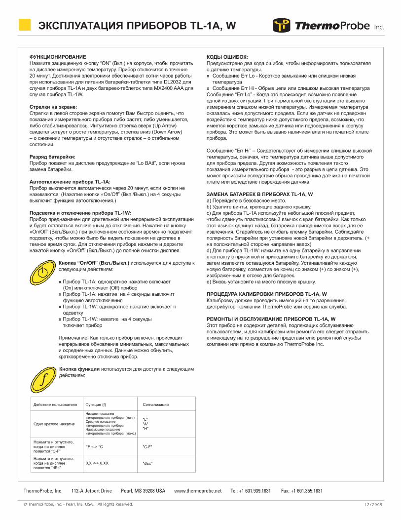
Кнопка функции используется для доступа к следующим действиям:
КОДЫ ОШИБОК:Предусмотрено два кода ошибок, чтобы информировать пользователя о датчике температуры. » Сообщение Err Lo - Короткое замыкание или слишком низкая
температура» Сообщение Err Hi - Обрыв цепи или слишком высокая температураСообщение “Err Lo” - Когда это происходит, возможно появление одной из двух ситуаций. При нормальной эксплуатации это вызвано измерением слишком низкой температуры. Измеряемая температура оказалась ниже допустимого предела. Если же датчик не подвержен воздействию температур ниже допустимого предела, возможно, что имеется короткое замыкание датчика или подсоединения к корпусу прибора. Это может быть вызвано наличием влаги на печатной плате прибора.
Сообщение “Err Hi” – Свидетельствует об измерении слишком высокой температуры, означая, что температура датчика выше допустимого для прибора предела. Другая возможность появления такого показания измерительного прибора - это разрыв в цепи датчика. Это может произойти вследствие обрыва проводника датчика на печатной плате или вследствие повреждения датчика.
ЗАМЕНА БАТАРЕЕК В ПРИБОРАХ TL-1A, W a) Перейдите в безопасное место.b) Удалите винты, крепящие заднюю крышку.c) Для прибора TL-1A используйте небольшой плоский предмет, чтобы сдвинуть пластмассовый язычок с края батарейки. Как только этот язычок сдвинут назад, батарейка приподнимется вверх для ее извлечения. Старайтесь не сгибать клемму батарейки. Соблюдайте полярность батарейки при установке новой батарейки в держатель. (+ на положительной стороне направлен вверх)d) Для прибора TL-1W: нажмите на одну батарейку в направлении к контакту с пружинкой и приподнимите батарейку из держателя, затем извлеките оставшуюся батарейку. Устанавливайте каждую новую батарейку, совместив ее конец со знаком (+) со знаком (+), изображенным в отсеке для батареек. e) Вновь установите на место плоскую крышку.
ПРОЦЕДУРА КАЛИБРОВКИ ПРИБОРОВ TL-1A, WКалибровку должен проводить имеющий на то разрешение дистрибутор компании ThermoProbe или сервисная служба.
РЕМОНТЫ И ОБСЛУЖИВАНИЕ ПРИБОРОВ TL-1A, WЭтот прибор не содержит деталей, подлежащих обслуживанию пользователем, и для калибровки или ремонта его следует отправить к имеющему на то разрешение представителю ремонтной службы компании или прямо в компанию ThermoProbe Inc.
ЭКСПЛУАТАЦИЯ ПРИБОРОВ TL-1A, W
Действие пользователя Функция (f) Сигнализация
Одно краткое нажатие
Низшее показание измерительного прибора (мин.), Среднее показание измерительного прибора Наивысшее показание измерительного прибора (макс.)
"L""A""H"
Нажмите и отпустите, когда на дисплее появится “C-F”
°F <-> °C "C-F"
Нажмите и отпустите, когда на дисплее появится “dEc”
0.X <-> 0.XX "dEc"
f
ESTE MANUAL DESCRIBE LA FUNCIÓN Y USOS BÁSICOS DE LOS INSTRUMENTOS THERMOPROBE Y LAS INSTRUCCIONES DE SEGURIDAD BÁSICAS.El termómetro electrónico portátil de ThermoProbe es un instrumento de temperatura digital portátil. La aplicación del ThermoProbe es tanto en áreas de peligro (inflam-ables) como no riesgosas. Este instrumento portátil está dirigido al uso de ATEX para condiciones secas (-20 a 40C). El instrumento no está destinado para su uso en instala-ciones exteriores permanentes y no está destinado ni probado para su uso en condiciones de congelamiento. En caso el equipo pueda estar expuesto a presiones externasextremas tales como vibración, calor e impacto, el equipo debe ser protegido.
© ThermoProbe, Inc. - Pearl, MS USA. All Rights Reserved. 1 2 / 2 0 09
ThermoProbe, Inc. 112-A Jetport Drive Pearl, MS 39208 USA www.thermoprobe.net Tel: +1 601.939.1831 Fax: +1 601.355.1831
TUSO DEL INSTRUMENTOLos instrumentos ThermoProbe están destinados para su operación en instala-ciones de riesgo (potencialmente inflamables o explosivas), el usuario debe tenerconocimiento en la operación de las instrucciones de seguridad apropiadas.
VEA LAS MARCAS EN EL INSTRUMENTO Y LEA LAS SIGUIENTESINSTRUCCIONES
PROCEDIMIENTOS ANTES DEL USOa) El inspector debe tener un conocimiento profundo de los productos que seránmedidos y debe conocer las medidas de seguridad a tomarse cuando se trabajacon el material que va a medirse.b) El instrumento debe ser revisado para descartar defectos graves; revise que elinstrumento se encuentre completo (cuando sea aplicable cable a tierra/deconexión), tenga buenas baterías, etc. De ser necesario, revise la exactitud de lamedición. Si se encuentra algún defecto, el instrumento no debe ser usado hastaque se haya realizado la reparación.c) El instrumento, especialmente el sensor (y cable), debe estar limpio porrazones de seguridad y facilidad de uso.d) La evaluación debe ser realizada para verificar si el lugar físico para lamedición es considerado de riesgo primario o secundario, o ambos.
FUNCIÓNPresiones el botón sellado de encendido "ON" en la caja para leer la temperaturamedida en la pantalla. El instrumento se apagará en 20 minutos.
SEGURIDAD INTRÍNSECAUn equipo seguro intrínsecamente se define como "un equipo y cableado que esincapaz de liberar suficiente energía eléctrica o térmica bajo condicionesnormales o anormales para ocasionar el encendido de una mezcla atmosféricaespecífica de riesgo en su concentración más fácilmente encendida" (ISA-RP12.6). Esto se logra limitando la cantidad de energía disponible hacia elequipo eléctrico en el área de riesgo hasta un nivel por debajo del que encen-dería los gases.
A fin de tener un incendio o una explosión, el combustible, el oxígeno o unafuente de encendido debe estar presente. Un sistema seguro intrínsecamenteasume que el combustible y el oxígeno se encuentran presentes en la atmósfera,pero el sistema está diseñado para de manear que la energía eléctrica o energíatérmica de un circuito de un instrumento particular nunca pueda ser mayor comopara ocasionar un encendido.
INSTRUCCIONES DE SEGURIDAD ADICIONALESa) La fuente de energía debe ser retirada antes de realizar algún manten-
imiento. b) Las baterías deben ser cambiadas en un área sin riesgos. Las baterías deben
ser del tipo correcto, vea las placas de identificación del instrumento en elinstrumento.
c) Las nuevas baterías no deben ser mezcladas con las antiguas; las baterías nodeben ser mezcladas con baterías de otros fabricantes.
d) El intercambio de componentes diferentes a los componentes originalespuede comprometer la seguridad y no es recomendable.
REQUISITOS ESENCIALES SOBRE SALUD Y SEGURIDADEl equipo está diseñado para satisfacer los requisitos de la cláusula 1.2.7 de losRequisitos Esenciales sobre Salud y Seguridad (Norma Europea).
NOTA DE ORIENTACIÓNProblemas con sustancias y ambientes agresivos: Esté alerta a las sustanciasagresivas y a que puede ser necesaria protección adicional. La exposición a calorexcesivo puede derretir los componentes plásticos del instrumento.
TP-7, 8, 2C, 5C: La soda cáustica, altamente básica y las sustancias ácidaserosionarán el sujetador y cable aluminio y de cobre del suelo. El montaje delsensor-cable posee superficies externas de acero inoxidable y de material defluoro polímero.
TL-1A, W: El sensor tiene superficies externas de acero inoxidable, el montajedel sensor es acetal, la caja es de aluminio, la empaquetadura de silicona y elmontaje de ventana de cambio es un compuesto de vinilo.
SIGNIFICACIÓN DE NORMASLos instrumentos de medición de ThermoProbe están clasificados como intrínse-camente seguros según las normas de Norteamérica, Europa y Japón.Dependiendo del instrumento particular y los requisitos regionales, los certifi-cados son proporcionados por los siguientes laboratorios de prueba: UL (US),KEMA (Holanda), DEMKO (Dinamarca), y TIIS (Japón). Sírvase revisar las placasde identificación del instrumento para la designación necesaria.
Clasificaciones de seguridadNorteamérica: Clase 1, División I, Grupos ABCD - Modelo TP-7, 8, 2C, 5CEuropa: ATEX código (II 2 G) DEMKO 03ATEX133416XII 2G EExia IIB T3 Modelo TP-7, 8 con batería Duracell II 2G EExia IIB T4 Modelo TP-7, 8 con batería Rayovac II 2G EExia IIC T3 Modelo TP-7, 8 con batería Duracell y cable especialII 2G EExia IIC T4 Modelo TP-7, 8 con batería Rayovac y cable especialII 2G EExia IIB T4 Modelo TP-2C, 5C con batería Duracell MX2400 II 2G EExia IIC T4 Modelo TL-1A con batería Duracell DL2032 II 2G EExia IIC T4 Modelo TL-1W con batería Duracell MX2400 Japón: EExia IIB T4 Modelo TP-7, 8
Las normas aplicables son: Designación de la agencia o de seguridad:Seguridad intrínseca UL 913 US: UL LogoSeguridad intrínseca CSA 22.2 Canadá: ULc LogoSeguridad intrínseca CENELEC EN50014 Europa: ATEX CE& Ex LogoSeguridad Intrínseca CENELEC EN50020 Europa: ATEX CE& Ex LogoEmisiones CENELEC EN50081 EMC Europa : ATEX CE& Ex LogoInmunidad CENELEC EN55022 EMC Europa : ATEX CE& Ex LogoJapón usa normas CENELEC Japón: TIIS sólo designación de texto
INSTRUCCIONES PARA USO DE THERMOPROBE INC.
© ThermoProbe, Inc. - Pearl, MS USA. All Rights Reserved. 1 2 / 2 0 09
ThermoProbe, Inc. 112-A Jetport Drive Pearl, MS 39208 USA www.thermoprobe.net Tel: +1 601.939.1831 Fax: +1 601.355.1831
FUNCIÓNPresione el botón sellado de encendido "ON" en la caja para leer la temperaturamedida en la pantalla. El instrumento se apagará en 20 minutos. La tecnologíaelectrónica permite cientos de horas de uso activados por una batería planaDL2032 en el caso del TL-1A, y dos baterías planas MX2400 AAA en el caso delTL-1W.
Flechas:Las flechas en el lado izquierdo de la pantalla le mostrarán en una mirada si lalectura está aumentando, disminuyendo o si se ha estabilizado. Intuitivamente laFlecha Hacia Arriba simboliza una temperatura en aumento, Flecha Hacia Abajoes una temperatura en descenso y ninguna flecha, un estado estabilizado.
Batería baja:El instrumento mostrará una señal de advertencia "Lo BAtt" (batería baja) si esnecesario cambiar la batería.
Auto apagado del TL-1A:La unidad se apagará automáticamente en 20 minutos si no se presiona ningúnbotón (Al presionar el botón de encendido/apagado "On/Off" durante 4 segundosse desactivará la función de auto apagado).
Retroiluminación y apagado del TL-1W:La unidad está destinada para una operación prolongada o continua ypermanecerá encendida hasta el apagado. Al presionar el botón deencendido/apagado On/Off durante el funcionamiento, se encenderá la retroilu-minación temporalmente de manera que la pantalla puede ser leída en condi-ciones de oscuridad. Para apagar el instrumento, presione y sujete el botón deencendido/apagado On/Off hasta que la pantalla se vuelva en blanco
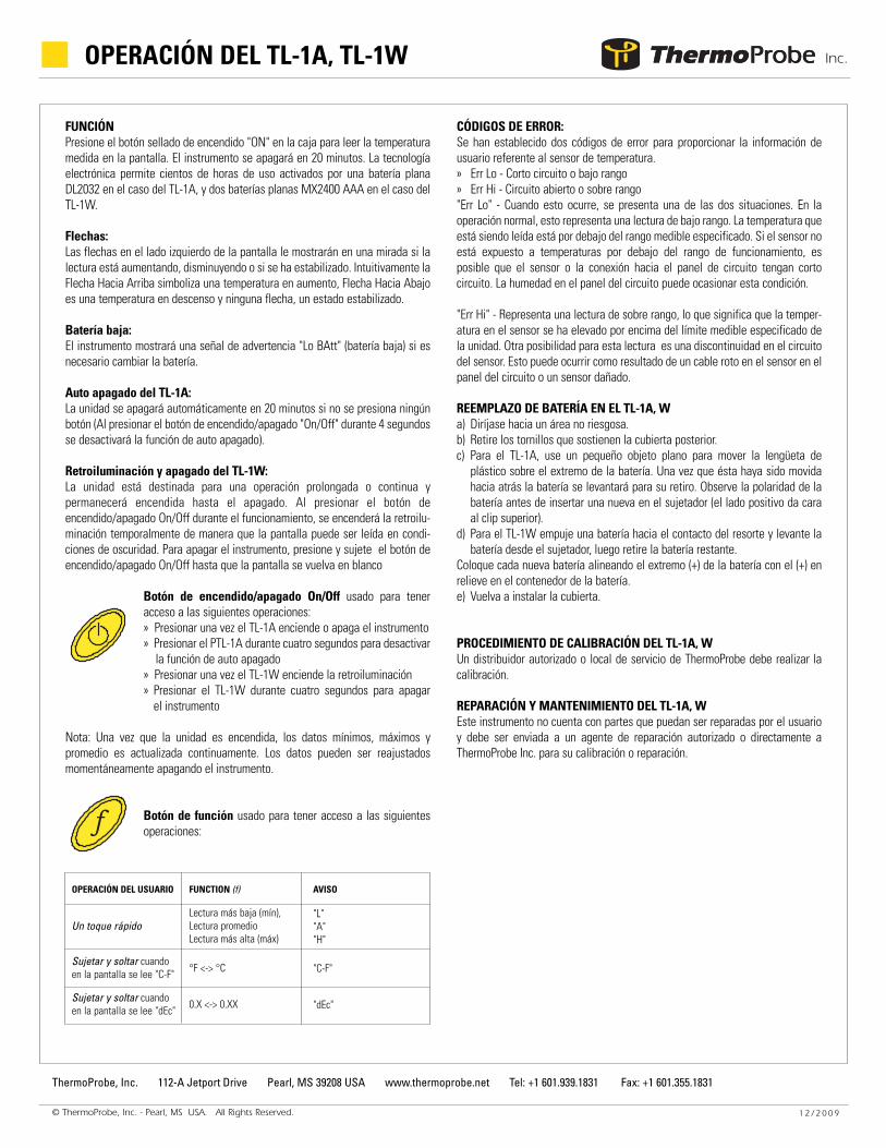
Botón de encendido/apagado On/Off usado para teneracceso a las siguientes operaciones:» Presionar una vez el TL-1A enciende o apaga el instrumento» Presionar el PTL-1A durante cuatro segundos para desactivar
la función de auto apagado» Presionar una vez el TL-1W enciende la retroiluminación» Presionar el TL-1W durante cuatro segundos para apagar
el instrumento
Nota: Una vez que la unidad es encendida, los datos mínimos, máximos ypromedio es actualizada continuamente. Los datos pueden ser reajustadosmomentáneamente apagando el instrumento.
Botón de función usado para tener acceso a las siguientesoperaciones:
CÓDIGOS DE ERROR:Se han establecido dos códigos de error para proporcionar la información deusuario referente al sensor de temperatura.» Err Lo - Corto circuito o bajo rango» Err Hi - Circuito abierto o sobre rango"Err Lo" - Cuando esto ocurre, se presenta una de las dos situaciones. En laoperación normal, esto representa una lectura de bajo rango. La temperatura queestá siendo leída está por debajo del rango medible especificado. Si el sensor noestá expuesto a temperaturas por debajo del rango de funcionamiento, esposible que el sensor o la conexión hacia el panel de circuito tengan cortocircuito. La humedad en el panel del circuito puede ocasionar esta condición.
"Err Hi" - Representa una lectura de sobre rango, lo que significa que la temper-atura en el sensor se ha elevado por encima del límite medible especificado dela unidad. Otra posibilidad para esta lectura es una discontinuidad en el circuitodel sensor. Esto puede ocurrir como resultado de un cable roto en el sensor en elpanel del circuito o un sensor dañado.
REEMPLAZO DE BATERÍA EN EL TL-1A, Wa) Diríjase hacia un área no riesgosa.b) Retire los tornillos que sostienen la cubierta posterior.c) Para el TL-1A, use un pequeño objeto plano para mover la lengüeta de
plástico sobre el extremo de la batería. Una vez que ésta haya sido movidahacia atrás la batería se levantará para su retiro. Observe la polaridad de labatería antes de insertar una nueva en el sujetador (el lado positivo da caraal clip superior).
d) Para el TL-1W empuje una batería hacia el contacto del resorte y levante labatería desde el sujetador, luego retire la batería restante.
Coloque cada nueva batería alineando el extremo (+) de la batería con el (+) enrelieve en el contenedor de la batería.e) Vuelva a instalar la cubierta.
PROCEDIMIENTO DE CALIBRACIÓN DEL TL-1A, W Un distribuidor autorizado o local de servicio de ThermoProbe debe realizar lacalibración.
REPARACIÓN Y MANTENIMIENTO DEL TL-1A, WEste instrumento no cuenta con partes que puedan ser reparadas por el usuarioy debe ser enviada a un agente de reparación autorizado o directamente aThermoProbe Inc. para su calibración o reparación.
OPERACIÓN DEL TL-1A, TL-1W
f
OPERACIÓN DEL USUARIO FUNCTION (f) AVISO
Un toque rápidoLectura más baja (mín),Lectura promedioLectura más alta (máx)
"L""A""H"
Sujetar y soltar cuandoen la pantalla se lee "C-F" °F <-> °C "C-F"
Sujetar y soltar cuandoen la pantalla se lee "dEc" 0.X <-> 0.XX "dEc"