instructions for editing and … 14...g. diagnostic tools: ... thyssenkrupp - mid rise ... g. kone...
TRANSCRIPT

INSTRUCTIONS FOR EDITING AND COORDINATION
SECTION 14210
ELECTRIC TRACTION ELEVATORS
2.01 Acceptable Manufacturers:
A. Coordinate basis of specification with drawing requirements. Actual model specified may be influenced by single or dual door access, number of stops, travel height, etc. Coordinate shaft dimensions with specified manufacturer and model. Height of shaft shown on drawings shall be coordinated with manufacturer’s travel height and overrun characteristics.
3.08 Elevator Schedule:
A. Review the entire schedule with the elevator manufacturer listed with actual project requirements and revise the schedule as fit.
11/17

SECTION 14210
ELECTRIC TRACTION ELEVATORS
PART 1 - GENERAL
1.01 RELATED DOCUMENTS
A. Drawings and general provisions of Contract, including General Conditions and Division-1 specification sections, apply to work of this section, with special attention to the following:
1. Section 01730: Operating and Maintenance Data.
2. Section 01530: Barriers - Separation of construction activities from occupied areas.
1.02 RELATED WORK
A. Section 03300: Cast in Place Concrete - Elevator pit.
B. Section 04200: Unit Masonry - Hoist way enclosure, building in of door frames.
C. Section 05120: Structural Steel - Hoist Beam.
D. Section 05500: Metal Fabrications - Pit ladder and support brackets for guide rails.
E. Section 07112: Bituminous Waterproofing.
F. Section 08710: Finish Hardware - Cylinder keying.
G. Section 09662 Resilient Tile Flooring (VCT)
H. Division 15 Specifications related to ventilation of Machine Room.
I. Division 16 Specifications covering:
1. Electric service with fused disconnect switches for elevator operating systems, including disconnecting device to elevator equipment prior to activation of sprinkler system.
2. Electric service to Controller Closet.
3. Receptacles in elevator pit and Controller Closet.
14210-1 11/17

ELECTRIC TRACTION ELEVATORS SECTION 14210
1.03 REFERENCE CODES AND STANDARDS
A. Americans with Disabilities Act Accessibility Guidelines (Appendix A to 28 CFR Part 36).
B. ICC/ANSI A117.1-1998 (“Accessible and Usable Buildings and Facilities”).
C. ASME 17-1-1996 Safety Code for Elevators and Escalators (with addenda, as referenced by the 2000 IBC, and incorporated into the 2000 USBC).
D. 1999 National Electric Code.
E. Applicable NEMA Standards.
F. Applicable Standards of the National Elevator Industry, Inc. (NEII), www.neii.org.
G. Applicable OSHA Standards (29 C.F.R. Part 1926).
1.04 PERFORMANCE REQUIREMENTS
A. Car Performance
1. Car Speed ± 5% of contract speed under any loading condition or direction of travel.
2. Car Capacity: Safely lower, stop and hold (per code) up to 125% of rated load.
B. System Performance
1. Vertical Vibration (maximum): 25 mg (Otis: 20)
2. Horizontal Vibration (maximum): 25 mg (Otis: 12)
3. Jerk Rate (maximum): 4.0 ft/sec3 (Otis: 4.9)
4. Acceleration (maximum) 1.5 ft/sec2 (Otis: 2.62)
5. In Car Noise: ≤ 55 dB(A) (Otis: 55-60)
6. Leveling Accuracy: ±0.2 inches (Otis: 0.375)
7. Starts per hour (maximum): 80
14210-2 11/17

ELECTRIC TRACTION ELEVATORS SECTION 14210
1.05 DESCRIPTION OF WORK
A. The work includes all material, labor and coordination required for the complete installation of the elevator.
B. Type of electric traction elevator service required is the following:
1. Passenger elevator.
1.06 QUALITY ASSURANCE
A. Manufacturers Qualifications: A company specializing in the manufacturing, installing and servicing of the type of elevator specified in this section.
B. Installer Qualifications: Installer shall be either the elevator manufacturer or a licensee of the manufacturer, shall have not less than 5 years successful experience with the installation of similar elevators.
C. Regulatory Requirements:
1. Elevator Code: Except for more stringent requirements as indicated or imposed by governing regulations (which must be complied with), comply with applicable requirements of ANSI/ASME A17.1, Safety Code for Elevators, and Escalators (hereinafter referred to as the "Code").
2. NFPA Code: Comply with applicable NFPA codes, and specifically with sections relating to electrical work and elevators.
3. Fire Resistance of Entrances: Comply with NFPA No. 80, and provide units bearing UL labels with 30-min. temperature rise on labels.
4. Standards for Accessibility: Except as otherwise indicated, comply with the accessibility requirements of the ADA Accessibility Guidelines and ICC/ANSI A117.1, including clearances, handrails, locations for signal equipment and similar provisions.
5. The elevator cab and all of the ancillary components shall meet the ADA and ICC/ANSI requirements, whether specifically noted or not.
1.07 SUBMITTALS
A. Product Data: Submit manufacturer's detailed technical product data and installation instruction for each principal component or product, and include certified test reports on required testing. List and describe features of control system, performances, and operating characteristics.
14210-3 11/17

ELECTRIC TRACTION ELEVATORS SECTION 14210
B. Shop Drawings: Provide plans, elevations, sections and details indicating service at landing, Machine Room layout, coordination with building structure, relationship to other work, and locations of equipment and signals. Show hoistway dimensions, travel and clearance dimensions for cabs. Indicate maximum load imposed on building and structure at support points. Include electrical characteristics and connection requirements. Drawings shall demonstrate compliance with accessibility requirements.
C. Samples: Submit samples of exposed finishes of car enclosures, hoistway entrances, and signal equipment. Provide 3” square samples of sheet materials and 4" lengths of running trim members.
D. Color charts: Submit manufacturers’ standard color selections for exposed car finishes.
E. Maintenance Manuals: Submit bound manual for each elevator or group of elevators, with operating and maintenance instructions, parts listing, recommended parts inventory listing, purchase source listing for major and critical components, emergency instructions, and similar information.
F. Certificates and Permits: Provide Owner with copies of all inspections/acceptance certificates and operating permits as required by governing authorities to allow normal, unrestricted use of elevators.
G. Diagnostic Tools: Prior to seeking final acceptance for the completed project as specified by the Contract Documents, the Elevator Contractor shall deliver to the Owner any specialized tool(s) that may be required to perform diagnostic evaluations, adjustments, and/or parametric software changes and/or test and inspections on any piece of control or monitoring equipment installed. This shall include any specialized tool(s) required for monitoring, inspection and/or maintenance where the means of suspension other than conventional wire ropes are furnished and installed by the Elevator Contractor.
1. The controls will not require an external diagnostic tool for normal maintenance purposes. Diagnostics capabilities are an integral part of the controls
2. Any and all such tool(s) shall become property of the Owner.
3. Any diagnostic tool provided to the Owner by the Elevator Contractor shall be configured to perform all levels of diagnostics, systems adjustment and parametric software changes which are available to the Elevator Contractor.
4. In those cases where diagnostic tools provided to the Owner require periodic recalibration/or re-initiation, the Elevator Contractor shall perform such tasks at no additional cost to the Owner for a period equal to the
14210-4 11/17

ELECTRIC TRACTION ELEVATORS SECTION 14210
term of the specified under maintenance service agreement.
1.08 DELIVERY, STORAGE AND HANDLING
A. Coordinate delivery of elevator material throughout construction.
B. Store elevator materials in protected environment in accordance with manufacturer recommendations.
1.09 WARRANTY
A. Provide a minimum one (1) year warranty for parts and materials, and minimum one (1) year warranty for labor. Refer to section 01740 for effective date of warranty commencement.
1.10 MAINTENANCE SERVICE
A. Provide maintenance service consisting of examinations and adjustments of the elevator equipment for a period of 12 months after date of Substantial Completion.
B. Maintenance service shall be provided by elevator manufacturer recommended service personnel. Manufacturer recommended parts and supplies shall be used in maintenance service as in the original manufacture and installation.
C. Maintenance service be performed during regular working hours of regular working days and shall include regular time call back service.
D. Maintenance service shall not include adjustments, repairs or replacement of parts due to negligence, misuse, abuse or accidents.
PART 2 - PRODUCTS
2.01 MANUFACTURER
A. Provide Traction Elevator by the following Manufacturer’s:
1. KONE, INC - Machine Room-Less EcoSpace™ traction elevators, One KONE Court, Moline, IL 61265 Tel 800-956-KONE www.kone.com – Basis of Design
2. ThyssenKrupp - Mid Rise – Traction Machine Room-Less (85S)
3. Otis Elevator Company - Gen2™ traction passenger elevators consisting of the following components:
4. Pre bid manufacturer in accordance with this section and Section 0163
14210-5 11/17

ELECTRIC TRACTION ELEVATORS SECTION 14210
B. All manufacturers to provide elevator consisting of the following components:
a. AC gearless machine using embedded permanent magnets mounted to the guide rails.
b. Polyurethane Coated-Steel Belts (CSB’s) for elevator hoisting purposes, Otis Elevator Company.
c. Provide Steel hoist cables of size and number to ensure proper wear qualities shall be used
d. Non-proprietary controls and technology.
2.02 MATERIALS
A. Steel
1. Sheet Steel for Exposed Work: Stretcher-leveled, cold-rolled, commercial-quality carbon steel, complying with ASTM A366, matte finish.
2. Sheet Steel for Unexposed Work: Hot-rolled, commercial-quality carbon steel, pickled and oiled, complying with ASTM A569.
3. Structural Steel Shapes and Plates: ASTM A36 and AISI 1018.
B. Stainless Steel: Type 300 Series complying with ASTM A167, with standard tempers and hardness required for fabrication, strength and durability.
1. Supply with mechanical finish on fabricated work in the location shown or specified with texture and reflectivity required (Federal and NAAMM nomenclature). Protect with adhesive plastic film or paper covering.
2. All finishes specified as “satin” to be manufacturer’s standard directional polish that complies with commercial No. 4 requirements.
3. Material may vary per specification.
C. Aluminum: Extrusions per ASTM B221; sheet and plate per ASTM B209.
D. Plastic Laminate: ASTM E84 Class A and NEMA LD3, 0-1/20” (1.3 mm) up to 01/16” (1.6 mm) nominal thickness. Exposed surfaces to have color selected by architect from manufacturer’s standard selection.
E. Fire-Retardant Treated Particleboard Panels: Minimum 0-1/2” (13 mm) thick backup for plastic laminate veneered panels, provided with suitable anti-warp
14210-6 11/17

ELECTRIC TRACTION ELEVATORS SECTION 14210
backing; to meet ASTM E84 Class “A” rating with flame-spread rating of 25 or less.
F. Paint:
1. Concealed Steel and Iron: Clean metal of oil, grease, scale and other foreign matter and paint one shop coat of manufacturer’s standard rust-resistant primer. Galvanized metal need not be painted.
2.03 EQUIPMENT: CONTROL COMPONENTS
A. Controller: Provide microcomputer based control system to perform all of the functions. The system shall also perform car and group operational control.
1. All high voltage (110V or above) contact points inside the controller cabinet shall be protected from accidental contact in a situation where the controller doors are open.
2. Controller shall be separated into two distinct halves; Motor Drive side and Control side. High voltage motor power conductors shall be routed and physically segregated from the rest of the controller.
3. Provide a serial cardrack and main CPU board containing a non-erasable EPROM and operating system firmware.
4. Variable field parameters and adjustments shall be contained in a nonvolatile memory module.
B. Drive: Provide Variable Voltage Variable Frequency AC drive system to develop high starting torque with low starting current.
B. Controller Location: Locate controller adjacent to the hoistway at closet on Ground Floor, or elevator contractor can locate the controller inside the hoistway at the upper landing (no control closet required for Otis unit).
2.04 EQUIPMENT: HOISTWAY COMPONENTS
A. Machine: AC gearless machine, with permanent magnet synchronous motor, direct current electro-mechanical disc brakes and integral traction drive sheave, mounted to the car guide rail at the top of the hoistway.
B. Governor: Friction type over-speed governor rated for the duty of the elevator specified.
C. Buffers, Car and Counterweight: Polyurethane buffer.
D. Hoistway Operating Devices:
14210-7 11/17

ELECTRIC TRACTION ELEVATORS SECTION 14210
1. Emergency stop switch in the pit
2. Terminal stopping switches.
3. Emergency stop switch on the machine
E. Positioning System: System consisting of magnets and proximity switches.
F. Guide Rails and Attachments: Steel rails with brackets and fasteners.
G. Provide five hoist ropes 10 mm diameter fabricated from steel wire wound about a steel core. Polyurethane coated belts with high-tensile-grade, zinc-plated steel cords is acceptable
H. Governor Rope: Provide 3/8-inch diameter steel cable governor rope minimum eight strands wound about a sisal core center.
I. Hoistway Entrances
1. Frames: 14-gauge sheet steel, bolted construction. 16-gauge is acceptable
2. Sills: extruded aluminum.
3. Doors: Hollow metal construction with vertical internal channel reinforcements.
4. Fire Rating: Entrance and doors shall be UL fire-rated for 1-1/2 hour.
5. Entrance Finish: Brushed stainless steel.
6. Entrance Markings Jamb Plates: Provide standard entrance jamb tactile markings on both jambs, at all floors. Plates shall be flush mount mounted. Plate finish to match flush mount.
2.05 EQUIPMENT: CAR COMPONENTS
A. Car Frame: Provide car frame with adequate bracing to support the platform and car enclosure.
B. Platform: Platform shall be all steel construction.
C. Car Guides: Provide guide-shoes mounted to top and bottom of both car and counterweight frame. Each guide-shoe assembly shall be arranged to maintain constant contact on the rail surfaces. Provide retainers in areas with Seismic design requirements.
14210-8 11/17

ELECTRIC TRACTION ELEVATORS SECTION 14210
D. Load weighing device shall be strain gauge type mounted to dead-end hitch attached atop the hoistway guide-rail.
E. Steel Cab
1. Panels: Non-removable vertical panels, plastic laminate selected from standard manufacturer’s catalog of choices. Trim and base plate to be aluminum with brushed finish.
2. Car Front Finish: Brushed stainless steel.
3. Car Door Finish: Brushed stainless steel.
4. Ceiling:
a. Round LED Down Light Drop Ceiling – LF-88: Satin Finish Stainless Steel three panel suspended ceiling with three holes per panel for Round LED lights
5. Handrail:
a. Round tube metal handrail of 3/8-inch thick by 1.5 inches tall. Material to be matte aluminum. Rails to be located on Sides and rear of car enclosure.
6. Flooring and Base: VCT (By others)
7. Threshold: Aluminum
F. Emergency Car Signals
1. Emergency Siren: Siren mounted on top of cab that is activated when the alarm button in the car operating panel is engaged. Siren shall have rated sound pressure level of 80 dB(A) at a distance of three feet from device. Siren shall respond with a delay of not more than one second after activation of alarm button.
2. Emergency Car Lighting: Provide emergency power unit employing a 12volt sealed rechargeable battery and totally static circuits shall illuminate the elevator car and provide current to the alarm bell in the event of building power failure.
3. Emergency Exit Contact: An electrical contact shall be provided on the car-top exit.
G. Ventilation: Power ventilation.
14210-9 11/17
ELECTRIC TRACTION ELEVATORS SECTION 14210
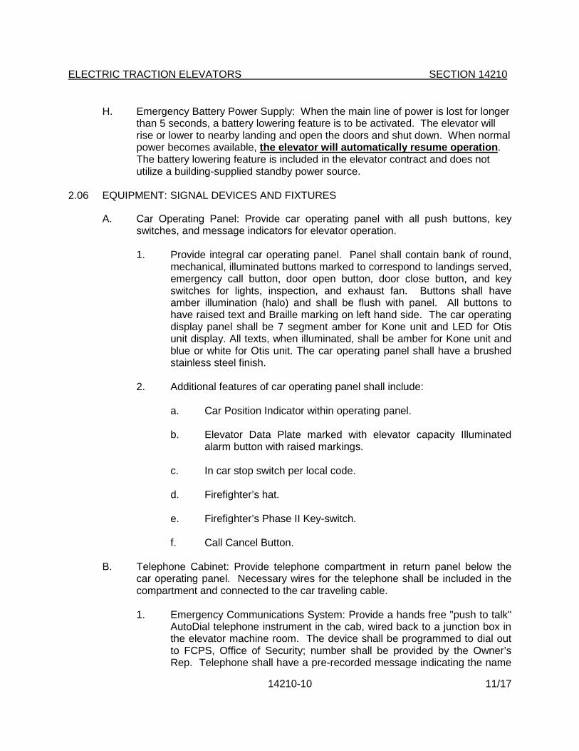
H. Emergency Battery Power Supply: When the main line of power is lost for longer than 5 seconds, a battery lowering feature is to be activated. The elevator will rise or lower to nearby landing and open the doors and shut down. When normal power becomes available, the elevator will automatically resume operation. The battery lowering feature is included in the elevator contract and does not utilize a building-supplied standby power source.
2.06 EQUIPMENT: SIGNAL DEVICES AND FIXTURES
A. Car Operating Panel: Provide car operating panel with all push buttons, key switches, and message indicators for elevator operation.
1. Provide integral car operating panel. Panel shall contain bank of round, mechanical, illuminated buttons marked to correspond to landings served, emergency call button, door open button, door close button, and key switches for lights, inspection, and exhaust fan. Buttons shall have amber illumination (halo) and shall be flush with panel. All buttons to have raised text and Braille marking on left hand side. The car operating display panel shall be 7 segment amber for Kone unit and LED for Otis unit display. All texts, when illuminated, shall be amber for Kone unit and blue or white for Otis unit. The car operating panel shall have a brushed stainless steel finish.
2. Additional features of car operating panel shall include:
a. Car Position Indicator within operating panel.
b. Elevator Data Plate marked with elevator capacity Illuminated alarm button with raised markings.
c. In car stop switch per local code.
d. Firefighter’s hat.
e. Firefighter’s Phase II Key-switch.
f. Call Cancel Button.
B. Telephone Cabinet: Provide telephone compartment in return panel below the car operating panel. Necessary wires for the telephone shall be included in the compartment and connected to the car traveling cable.
1. Emergency Communications System: Provide a hands free "push to talk" AutoDial telephone instrument in the cab, wired back to a junction box in the elevator machine room. The device shall be programmed to dial out to FCPS, Office of Security; number shall be provided by the Owner’s Rep. Telephone shall have a pre-recorded message indicating the name
14210-10 11/17

ELECTRIC TRACTION ELEVATORS SECTION 14210
of the school and the address. Wiring from the junction box back to the telephone board shall be installed by Owner. System shall comply with ASME A17.1 and the ADA Accessibility Guidelines.
C. Hall Fixtures: Hall fixtures shall be provided with necessary push buttons and key switches for elevator operation. Hall fixtures shall have a brushed stainless steel finish.
1. Hall fixtures shall feature round, mechanical, illuminated buttons in raised fixture housings. Hall fixtures shall correspond to options available from that landing. Buttons shall be flat flush in vertically mounted fixture. Hall Lanterns and hall indicators shall feature amber illumination, all numbers will for 7 segment amber for Kone unit or LED display
D. Car Lantern and Chime: A directional lantern visible from the corridor shall be provided in the car entrance. When the car stops and the doors are opening, the lantern shall indicate the direction in which the car is to travel and a chime will sound. The chime will sound once for up and twice for down.
E. Access key-switch at lowest floor in entrance jamb.
2.07 EQUIPMENT: ELEVATOR OPERATION AND CONTROLLER
A. Elevator Operation
Simplex Collective Operation: Using a microprocessor-based controller, the operation shall be automatic by means of the car and hall buttons. If all calls in the system have been answered, the car shall park at the last landing.
B. Standard Operating Features to include:
1. Full Collective Operation
2. Fan and Light Control.
3. Load Weighing Bypass.
4. Independent Service.
5. Ascending Car Uncontrolled Movement Protection
6. Top of Car Inspection Station.
C. Additional Operating Features to include:
1. Independent Service.
14210-11 11/17

ELECTRIC TRACTION ELEVATORS SECTION 14210
2. Directional hall lanterns, emergency car light power supply, two-beam light ray door protection, car ventilation blower, hoistway access package, protective pads and hooks, certificate frame, and special emergency service.
3. Provide emergency power to the elevator lights.
4. Hall switches shall be key type. Cylinder shall be Schlage and provided under Section 08710. Three (3) keys shall be provided.
5. Provisions for handicapped: Handicapped markings for hall and car buttons, adjustable door open times, audible floor approach signal in car, and Braille markings.
a. The floor and control buttons shall be located not more than forty-eight inches (48") above the floor, nor less than 35” above the floor.
b. Braille plates shall be provided adjacent to all cab control and switches.
c. Braille plates shall be provided for designation on each floor, 60” above the floor, on the fixed point at the open side of the elevator door.
d. Visible signals shall be a minimum of 72” above the floor.
D. Elevator Control System for Inspections and Emergency
1. Provide devices within controller to run the elevator in inspection operation.
2. Provide devices on car top to run the elevator in inspection operation.
3. Provide within controller an emergency stop switch to disconnect power from the brake and prevents motor from running.
4. Provide the means from the controller to mechanically lift and control the elevator brake to safely bring car to nearest available landing when power is interrupted.
5. Provide the means from the controller to reset the governor over speed switch and also trip the governor.
6. Provide the means from the controller to reset the emergency brake when set because of an unintended car movement or ascending car over speed.
14210-12 11/17

ELECTRIC TRACTION ELEVATORS SECTION 14210
7. Provide the means for the control to reset elevator earthquake operation.
2.08 EQUIPMENT: DOOR OPERATOR AND CONTROL
A. Door Operator: A closed loop permanent magnet VVVF high-performance door operator shall be provided to open and close the car and hoistway doors simultaneously. Door movement shall be cushioned at both limits of travel. Electro-mechanical interlock shall be provided at each hoistway entrance to prevent operation of the elevator unless all doors are closed and locked. An electric contact shall be provided on the car at each car entrance to prevent the operation of the elevator unless the car door is closed.
B. The door operator shall be arranged so that, in case of interruption or failure of electric power, the doors can be readily opened by hand from within the car, in accordance with applicable code. Emergency devices and keys for opening doors from the landing shall be provided as required by local code.
C. Doors shall open automatically when the car has arrived at or is leveling at the respective landings. Doors shall close after a predetermined time interval or immediately upon pressing of a car button. A door open button shall be provided in the car. Momentary pressing of this button shall reopen the doors and reset the time interval.
D. Door hangers and tracks shall be provided for each car and hoistway door. Tracks shall be contoured to match the hanger sheaves. The hangers shall be designed for power operation with provisions for vertical and lateral adjustment. Hanger sheaves shall have polyurethane tires and pre-lubricated sealed-for-life bearings.
E. Electronic Door Safety Device. The elevator car shall be equipped with an electronic protective device extending the full height of the car. When activated, this sensor shall prevent the doors from closing or cause them to stop and reopen if they are in the process of closing. The doors shall remain open as long as the flow of traffic continues and shall close shortly after the last person passes through the door opening.
2.09 SIGNAGE:
A. ADA Compliance: Provide visual, audible, and tactile signage and function communications in accordance with ICC/ANSI 117.1-1998, Section 407.3, New Destination-Oriented Elevators.
B. Medical Emergency Signage: Provide the international symbol for medical emergencies (star of life) on the inside face of each elevator hoistway jamb. Signage shall not be less than 3” high and placed 36” above finished floor when measured to center of symbol.
14210-13 11/17

ELECTRIC TRACTION ELEVATORS SECTION 14210
2.10 CONTROLLER CLOSET:
A: Controller closet shall be provided adjacent to the hoistway.
1. The controller closet for simplex cars shall be 3’-6”L x 20” deep x 7’-6” high (minimum dimensions) with a 3’-0” wide door.
2. A disconnect shall be provided for each elevator in the controller closet (by others)
PART 3 - EXECUTION
3.01 EXAMINATION
A. Field measure and examine substrates, supports, and other conditions under which elevator work is to be performed.
B. Do not proceed with work until unsatisfactory conditions are corrected.
3.02 PREPARATION
A. Coordinate installation of anchors, bearing plates, brackets and other related accessories.
3.03 INSTALLATION
A. Install equipment, guides, controls, car and accessories in accordance with manufacturer installation methods and recommended practices.
B. Properly locate guide rails and related supports at locations in accordance with manufacturer’s recommendations and approved shop drawings. Anchor to building structure using isolation system to minimize transmission of vibration to structure.
C. All hoistway frames shall be securely fastened to fixing angles mounted in the hoistway. Coordinate installation of sills and frames with other trades.
D. Lubricate operating system components in accordance with manufacturer recommendations.
E. Perform final adjustments, and necessary service prior to substantial completion.
3.04 FIELD QUALITY CONTROL
14210-14 11/17
ELECTRIC TRACTION ELEVATORS SECTION 14210
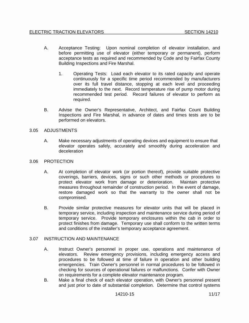
A. Acceptance Testing: Upon nominal completion of elevator installation, and before permitting use of elevator (either temporary or permanent), perform acceptance tests as required and recommended by Code and by Fairfax County Building Inspections and Fire Marshal.
1. Operating Tests: Load each elevator to its rated capacity and operate continuously for a specific time period recommended by manufacturers over its full travel distance, stopping at each level and proceeding immediately to the next. Record temperature rise of pump motor during recommended test period. Record failures of elevator to perform as required.
B. Advise the Owner’s Representative, Architect, and Fairfax Count Building Inspections and Fire Marshal, in advance of dates and times tests are to be performed on elevators.
3.05 ADJUSTMENTS
A. Make necessary adjustments of operating devices and equipment to ensure that elevator operates safely, accurately and smoothly during acceleration and deceleration
3.06 PROTECTION
A. At completion of elevator work (or portion thereof), provide suitable protective coverings, barriers, devices, signs or such other methods or procedures to protect elevator work from damage or deterioration. Maintain protective measures throughout remainder of construction period. In the event of damage, restore damaged work so that the warranty to the owner shall not be compromised.
B. Provide similar protective measures for elevator units that will be placed in temporary service, including inspection and maintenance service during period of temporary service. Provide temporary enclosures within the cab in order to protect finishes from damage. Temporary use shall conform to the written terms and conditions of the installer’s temporary acceptance agreement.
3.07 INSTRUCTION AND MAINTENANCE
A. Instruct Owner's personnel in proper use, operations and maintenance of elevators. Review emergency provisions, including emergency access and procedures to be followed at time of failure in operation and other building emergencies. Train Owner's personnel in normal procedures to be followed in checking for sources of operational failures or malfunctions. Confer with Owner on requirements for a complete elevator maintenance program.
B. Make a final check of each elevator operation, with Owner's personnel present and just prior to date of substantial completion. Determine that control systems
14210-15 11/17

ELECTRIC TRACTION ELEVATORS SECTION 14210
and operating devices are functioning properly.
C. Continuing maintenance: installer shall provide a continuing maintenance proposal to Owner, in the form of a standard yearly (or other period) maintenance agreement, starting on date construction contract maintenance requirements are concluded. State services, obligations and terms for agreement period, and for renewal options.
3.08 SCHEDULE
A. Elevator Equipment: KONE EcoSpace™ gearless traction elevator (Basis of Design)
B. Equipment Control: KCM831
C. Quantity of Elevator: (1) One
D. Number of Stops: Two
E. Openings: 2 Front Openings, 0 Rear Openings
F. Rise: 14ft
G. Rated Capacity: 2500#
H. Rated Speed: 150 fpm
I. Clear Inside Dimensions (W x D): 6’-8" x 4’-4"
J. Cab Height: 9’-0”
K. Clear height under suspended ceiling: 9 Ft
L. Entrance Width & Type: 3’-6", Single slide right
M. Entrance Height: 7’-0"
N. Main Power Supply: 480 Volts + 5%, three-phase (Verify Power Requirements)
O. Operation: Simplex (one car)
P. Machine Location: Inside the hoistway mounted on car guide rail
Q. Elevator Equipment shall conform to the requirements of seismic zone: 1
END OF SECTION
14210-16 11/17

INSTRUCTIONS FOR EDITING
SECTION 14240
HOLELESS HYDRAULIC ELEVATORS
2.01 Acceptable Manufacturers: Coordinate basis of specification with drawing requirements. Actual model specified may be influenced by single or dual door access, number of stops, travel height, etc. Coordinate shaft dimensions with specified manufacturer and model. Height of shaft shown on drawings shall be coordinated with manufacturer’s travel height and overrun characteristics.
2.02. C Elevator Schedule: Complete items 4 and 5 based on actual project requirements.
11/17

SECTION 14240
HOLELESS HYDRAULIC ELEVATORS
PART 1 - GENERAL
1.01 RELATED DOCUMENTS
A. Drawings and general provisions of Contract, including General Conditions and Division-1 specification sections, apply to work of this section, with special attention to the following:
1. Section 01730: Operating and Maintenance Data.
2. Section 01530: Barriers - Separation of construction activities from occupied areas.
1.02 RELATED WORK
A. Section 03300: Cast in Place Concrete - Elevator pit.
B. Section 04200: Unit Masonry - Hoist way enclosure, building in of door frames.
C. Section 05120: Structural Steel - Hoist Beam.
D. Section 05500: Metal Fabrications - Pit ladder and support brackets for guide rails.
E. Section 07112: Bituminous Waterproofing.
F. Section 08710: Finish Hardware - Cylinder keying.
G. Section 09680: Carpet – Car Flooring.
H. Division 15 Specifications related to ventilation of Machine Room.
I. Division 16 Specifications covering:
1. Electric service with fused disconnect switches for elevator operating systems, including disconnecting device to elevator equipment prior to activation of sprinkler system.
2. Electric service to Machine Room.
3. Receptacles in elevator pit and Machine Room.
14240-1 11/17

HOLELESS HYDRAULIC ELEVATORS SECTION 14240
1.03 REFERENCE CODES AND STANDARDS
A. Americans with Disabilities Act Accessibility Guidelines (Appendix A to 28 CFR Part 36).
B. ICC/ANSI A117.1-1998 (“Accessible and Usable Buildings and Facilities”).
C. ASME 17-1-1996 Safety Code for Elevators and Escalators (with addenda, as referenced by the 2000 IBC, and incorporated into the 2000 USBC).
D. 1999 National Electric Code.
E. Applicable NEMA Standards.
F. Applicable Standards of the National Elevator Industry, Inc. (NEII), www.neii.org.
G. Applicable OSHA Standards (29 C.F.R. Part 1926).
1.04 DESCRIPTION OF WORK
A. The work includes all material, labor and coordination required for the complete installation of the elevator.
B. Type of holeless hydraulic elevator service required is the following:
1. Passenger elevator.
C. Definitions: Hydraulic elevator work is hereby defined to include systems in which cars are hoisted by action of a hydraulic holeless unit, with other components of the work including fluid storage tank, pump, piping, valves, car enclosures, hoistway entrances, control systems, signal equipment, guide rails, electrical wiring, roping, buffers, and devices for operating, dispatching, safety, security, leveling, alarm, maintenance and similar required performances and capabilities.
1.05 QUALITY ASSURANCE
A. Manufacturers Qualifications: A company specializing in the manufacturing, installing and servicing of the type of elevator specified in this section.
B. Installer Qualifications: Installer shall be either the elevator manufacturer or a licensee of the manufacturer, shall have not less than 5 years successful experience with the installation of similar elevators.
14240-2 11/17

HOLELESS HYDRAULIC ELEVATORS SECTION 14240
C. Regulatory Requirements:
1. Elevator Code: Except for more stringent requirements as indicated or imposed by governing regulations (which must be complied with), comply with applicable requirements of ANSI/ASME A17.1, Safety Code for Elevators, and Escalators (hereinafter referred to as the "Code").
2. NFPA Code: Comply with applicable NFPA codes, and specifically with sections relating to electrical work and elevators.
3. Fire Resistance of Entrances: Comply with NFPA No. 80, and provide units bearing UL labels with 30-min. temperature rise on labels.
4. Standards for Accessibility: Except as otherwise indicated, comply with the accessibility requirements of the ADA Accessibility Guidelines and ICC/ANSI A117.1, including clearances, handrails, locations for signal equipment and similar provisions.
5. The elevator cab and all of the ancillary components shall meet the ADA and ICC/ANSI requirements, whether specifically noted or not.
1.06 SUBMITTALS
A. Product Data: Submit manufacturer's detailed technical product data and installation instruction for each principal component or product, and include certified test reports on required testing. List and describe features of control system, performances, and operating characteristics.
B. Shop Drawings: Provide plans, elevations, sections and details indicating service at landing, Machine Room layout, coordination with building structure, relationship to other work, and locations of equipment and signals. Show hoistway dimensions, travel and clearance dimensions for cabs. Indicate maximum load imposed on building and structure at support points. Include electrical characteristics and connection requirements. Drawings shall demonstrate compliance with accessibility requirements.
C. Samples: Submit samples of exposed finishes of car enclosures, hoistway entrances, and signal equipment. Provide 3” square samples of sheet materials and 4" lengths of running trim members.
D. Color charts: Submit manufacturers’ standard color selections for exposed car finishes.
E. Maintenance Manuals: Submit bound manual for each elevator or group of elevators, with operating and maintenance instructions, parts listing, recommended parts inventory listing, purchase source listing for major and critical components, emergency instructions, and similar information.
14240-3 11/17

HOLELESS HYDRAULIC ELEVATORS SECTION 14240
F. Certificates and Permits: Provide Owner with copies of all inspections/acceptance certificates and operating permits as required by governing authorities to allow normal, unrestricted use of elevators.
1.07 WARRANTY
A. Provide a minimum one (1) year warranty for parts and materials, and minimum one (1) year warranty for labor. Provide minimum five (5) year warranty covering pump and controls. Refer to section 01740 for effective date of warranty commencement.
PART 2 - PRODUCTS
2.01 ACCEPTABLE MANUFACTURERS
A. Approved Manufacturers (Holeless Elevator): Subject to compliance with requirements, manufacturers offering products which may be incorporated in the work include, but are not limited to, the following:
1. ThyssenKrupp Elevator, Memphis, TN, 1-877-230-0303 (www.thyssenkruppelevator.com) "Cimarron-25" HLS Series (Holeless) (door access on one side of cab) or Marquis 25 HLS (door access on two sides of cab), shall be the basis of specification. Other manufacturers listed below shall be acceptable.
2. Schindler 330A (Holeless), Morristown, NJ, 1-973-397-6500 (www.us.schindler.com)
3. Otis Elevator Co. (Holeless Hydraulic), Farmington, CT, 1-800-441-6847 (www.otis.com)
B. Other manufacturers offering "Holeless" design utilizing dual self-aligning jack assemblies, pre-bid approved in accordance with Section 01630, shall be acceptable providing that such systems shall comply with all other requirements of this Section.
2.02 MATERIALS AND COMPONENTS
A. General Requirement: Provide manufacturer's standard pre-engineered elevator systems which will comply with or fulfill the requirements of elevator schedule or, at manufacturer's option, provide custom manufactured elevator systems which will fulfill requirements. Where components are not otherwise indicated, provide standard components, published by manufacturer as included in standard pre-engineered elevator systems, and as required for a complete system.
14240-4 11/17

HOLELESS HYDRAULIC ELEVATORS SECTION 14240
B. Hydraulic Machines and Elevator Equipment.
1. General: Provide manufacturer's standard holeless hydraulic unit for elevator, with electric pump-tank-control system equipment in machine room.
C. Elevator Schedule
1. Power Unit: Manufacturer's standard power unit.
2. Capacity: 2,500 pounds minimum.
3. Speed: 100 feet per minute up; 150 feet per minute down.
4. Maximum rise: .
5. Number of stops and openings: stops, openings.
6. Leveling: Two-way leveling.
7. Control: Manufacturer's standard microprocessor based controller.
8. Inspection Operation: Top-of car inspection.
9. Minimum clear inside car dimension: 6'-8" x 4'-3".
10. Car Enclosure: Car shall be manufacturer’s enameled steel car enclosure. Car shall have vertical plastic laminate panels consisting of plastic laminate adhesively applied to ½” thick fire retardant treated particle board, mounted on baked enamel metal panel walls. Ceiling shall be manufacturer's standard downlight with "egg crate" panels. Floor shall be prepared for carpet supplied and installed as part of Division 9. Handrails shall be contoured oak and mounted at handicap height. Doors shall be stainless steel. All colors shall be selected from manufacturer's standard colors.
11. Car Operating Devices: Mounted in swing-type stainless steel front return panel above telephone/service cabinet. Mount at the required height for accessibility (See Quality Assurance, 1.05-C-4).
12. Car Doors: Single slide, left or right handed as shown on drawings, 3'-6" wide x 7'-0" high. Doors and frames shall be 1-hour fire rated.
a. Doors and frames shall be stainless steel. Doors shall be flush, hollow metal construction.
13. Door Operation: Micro-processor controlled, direct current powered.
14240-5 11/17

HOLELESS HYDRAULIC ELEVATORS SECTION 14240
14. Signals: Manufacturer's standard signals, mounted at the required handicap height.
15. Additional Features:
a. Directional hall lanterns, emergency car light power supply, two-beam light ray door protection, car ventilation blower, hoistway access package, protective pads and hooks, certificate frame, and special emergency service.
b. Hall switches at each floor stop shall be key type. Cylinder shall be Schlage and provided under Section 08710. Three (3) keys shall be provided.
c. Provisions for handicapped: Handicapped markings for hall and car buttons, adjustable door open times, audible floor approach signal in car, and Braille markings.
1) The floor and control buttons shall be located not more than forty-eight inches (48") above the floor, nor less than 35” above the floor.
2) Braille plates shall be provided adjacent to all cab control and switches.
3) Braille plates shall be provided for designation on each floor, 60” above the floor, on the fixed point at the open side of the elevator door.
4) Visible signals shall be a minimum of 72” above the floor.
5) Emergency Communications System: Provide a hands free "push to talk" AutoDial telephone instrument in the cab, wired back to a junction box in the elevator machine room. The device shall be programmed to dial out to FCPS, Office of Security; number shall be provided by Owner’s Rep. Telephone shall have a pre-recorded message indicating the name of the school and the address. Wiring from the junction box back to the telephone board shall be installed by Owner. System shall comply with ASME A17.1 and the ADA Accessibility Guidelines.
16. Special Features: Provide emergency power to the elevator lights.
17. Motor: 20 H.P. motor, 480V, 3 phase, 60 cycles with a reduced voltage starter.
14240-6 11/17

HOLELESS HYDRAULIC ELEVATORS SECTION 14240
18. Alarm Bell: An emergency alarm bell shall be located in conformance with ANSI A-17.1 code requirements and connected to a plainly marked pushbutton in the car.
19. Guide and Guide Shoes: Guides for the elevator car shall be planed steel elevator guide rails, properly fastened to the building structure with steel brackets. The car stile shall be fitted at top and bottom with guide shoes of the self-aligning, swivel type, with metal body and removable non-metallic liners.
20. Wiring, Piping and Oil: All necessary wiring shall be furnished and installed in the hoistway in accord with the National Electrical Code. All necessary pipe and fittings to connect the power unit to the jack unit and oil of the proper grade shall be furnished.
21. Mainline Strainer: A mainline strainer of the self-cleaning type, shall be furnished and installed in the oil line.
22. Automatic Guide Rail Lubricators: Lubricators shall be provided and mounted on top of upper guide shoes. Wool felt wiper shall apply an even, uniform flow of oil which shall thoroughly lubricate faces of guide rail from a leak-proof oil reservoir.
23. Failure Protection: The electrical control circuit shall be designed so that if a malfunction should occur due to motor starter failure, oil becoming low in the system, or the car failing to reach a landing in the up direction within a pre-determined time, the elevator call will automatically descend to the lowest terminal landing. If power operated doors are used, the doors will automatically open when the car reaches that landing to allow passenger to depart. The doors will then automatically close and all controls buttons except the door open button in the car station shall be made inoperative.
24. Oil Hydraulic Silencer (Muffler Device) shall be installed in oil line near power unit. It shall contain pulsation-absorbing material inserted in a blowout-proof housing arranged for inspecting interior parts without removing unit from oil line. Rubber hose without blowout-proof features will not be acceptable.
25. Buffers: Helical coil spring type
26. Vibration Pads shall be mounted under the power unit assembly to isolate the unit from the building structure.
27. Emergency Terminal Stopping Device: An emergency terminal stopping device for speeds over 100 FPM shall be provided which shall operate independently of the normal terminal stopping device should it fail to slow
14240-7 11/17

HOLELESS HYDRAULIC ELEVATORS SECTION 14240
down the car at the terminal as intended. They shall be so designed and installed that a single short circuit caused by a combination of grounds, or by other conditions, shall not prevent their functioning. The normal and emergency terminal stopping devices shall not control the same controller switches unless two or more separate and independent switches are furnished, two of which shall be closed in either direction of travel to complete the circuit to the control valve solenoids in the down direction and to complete the circuit to the pump motor for the up direction of travel.
28. Fire Department Control: The elevator system shall include provisions for emergency operation by the Fire Department, including recall and emergency shut-off provisions prior to sprinkler activation.
29. Protective Padding: Provide removable protective pads, sized to fit dimensions of cab enclosure.
PART 3 - EXECUTION
3.01 INSPECTION
A. Prior to commencing elevator installation, inspect hoistways, hoistway openings, pits and machine rooms, as constructed, verify all critical dimensions, and examine supporting structure and all other conditions under which elevator work is to be installed. Notify the owner’s Representative and Architect in writing of any dimensional discrepancies or other conditions detrimental to the proper installation or performance of elevator work. Do not proceed with elevator installation until unsatisfactory conditions have been corrected in a manner acceptable to the Installer.
3.02 INSTALLATION OF ELEVATOR SYSTEM
A. General: Comply with manufacturer's written instructions and recommendations for work required during installation. Provide temporary electrical power for installation operations and for testing of elevator components. Control access to hoistway and provide safety barriers at hoistway openings.
B. Install plunger-cylinder units plumb and accurately placed for proper elevator car position and travel; anchor securely in place.
C. Welded Construction: Provide welded connections for installation of elevator work where bolted connections are not required for subsequent removal or for normal operation, adjustment, inspection, maintenance and replacement of worn parts. Comply with AWS standards for workmanship and for qualifications of welding operators.
14240-8 11/17
HOLELESS HYDRAULIC ELEVATORS SECTION 14240
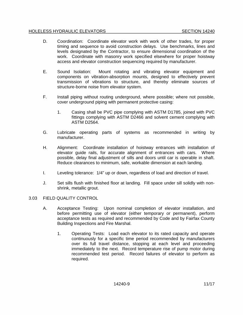
D. Coordination: Coordinate elevator work with work of other trades, for proper timing and sequence to avoid construction delays. Use benchmarks, lines and levels designated by the Contractor, to ensure dimensional coordination of the work. Coordinate with masonry work specified elsewhere for proper hoistway access and elevator construction sequencing required by manufacturer.
E. Sound Isolation: Mount rotating and vibrating elevator equipment and components on vibration-absorption mounts, designed to effectively prevent transmission of vibrations to structure, and thereby eliminate sources of structure-borne noise from elevator system.
F. Install piping without routing underground, where possible; where not possible, cover underground piping with permanent protective casing:
1. Casing shall be PVC pipe complying with ASTM D1785, joined with PVC fittings complying with ASTM D2466 and solvent cement complying with ASTM D2564.
G. Lubricate operating parts of systems as recommended in writing by manufacturer.
H. Alignment: Coordinate installation of hoistway entrances with installation of elevator guide rails, for accurate alignment of entrances with cars. Where possible, delay final adjustment of sills and doors until car is operable in shaft. Reduce clearances to minimum, safe, workable dimension at each landing.
I. Leveling tolerance: 1/4” up or down, regardless of load and direction of travel.
J. Set sills flush with finished floor at landing. Fill space under sill solidly with non-shrink, metallic grout.
3.03 FIELD QUALITY CONTROL
A. Acceptance Testing: Upon nominal completion of elevator installation, and before permitting use of elevator (either temporary or permanent), perform acceptance tests as required and recommended by Code and by Fairfax County Building Inspections and Fire Marshal.
1. Operating Tests: Load each elevator to its rated capacity and operate continuously for a specific time period recommended by manufacturers over its full travel distance, stopping at each level and proceeding immediately to the next. Record temperature rise of pump motor during recommended test period. Record failures of elevator to perform as required.
14240-9 11/17

HOLELESS HYDRAULIC ELEVATORS SECTION 14240
B. Advise the Owner’s Representative, Architect, and Fairfax Count Building Inspections and Fire Marshal, in advance of dates and times tests are to be performed on elevators.
3.04 ADJUSTMENTS
A. Make necessary adjustments of operating devices and equipment to ensure that elevator operates safely, accurately and smoothly during acceleration and deceleration
3.05 PROTECTION
A. At completion of elevator work (or portion thereof), provide suitable protective coverings, barriers, devices, signs or such other methods or procedures to protect elevator work from damage or deterioration. Maintain protective measures throughout remainder of construction period. In the event of damage, restore damaged work so that the warranty to the owner shall not be compromised.
B. Provide similar protective measures for elevator units that will be placed in temporary service, including inspection and maintenance service during period of temporary service. Provide temporary enclosures within the cab in order to protect finishes from damage. Temporary use shall conform to the written terms and conditions of the installer’s temporary acceptance agreement.
3.06 INSTRUCTION AND MAINTENANCE
A. Instruct Owner's personnel in proper use, operations and maintenance of elevators. Review emergency provisions, including emergency access and procedures to be followed at time of failure in operation and other building emergencies. Train Owner's personnel in normal procedures to be followed in checking for sources of operational failures or malfunctions. Confer with Owner on requirements for a complete elevator maintenance program.
B. Make a final check of each elevator operation, with Owner's personnel present and just prior to date of substantial completion. Determine that control systems and operating devices are functioning properly.
C. Continuing maintenance: installer shall provide a continuing maintenance proposal to Owner, in the form of a standard yearly (or other period) maintenance agreement, starting on date construction contract maintenance requirements are concluded. State services, obligations and terms for agreement period, and for renewal options.
END OF SECTION
14240-10 11/17

INSTRUCTIONS FOR EDITING
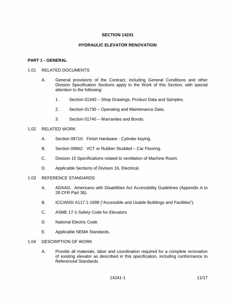
SECTION 14241
HYDRAULIC ELEVATOR RENOVATION
1. Existing elevator system shall be surveyed by the Maintenance Service contractor or by a local firm specializing in the installation and maintenance of hydraulic elevators. The survey shall determine the extent of modification required to satisfy the criteria of this Section.
2. Based upon the survey, edit this Section to add or delete requirements as listed in Part 2.
11/17
SECTION 14241
HYDRAULIC ELEVATOR RENOVATION
PART 1 - GENERAL
1.01 RELATED DOCUMENTS
A. General provisions of the Contract, including General Conditions and other Division Specification Sections apply to the Work of this Section, with special attention to the following:
1. Section 01340 – Shop Drawings, Product Data and Samples.
2. Section 01730 – Operating and Maintenance Data.
3. Section 01740 – Warranties and Bonds.
1.02 RELATED WORK
A. Section 08710: Finish Hardware - Cylinder keying.
B. Section 09662: VCT or Rubber Studded – Car Flooring.
C. Division 15 Specifications related to ventilation of Machine Room.
D. Applicable Sections of Division 16, Electrical.
1.03 REFERENCE STANDARDS
A. ADAAG: Americans with Disabilities Act Accessibility Guidelines (Appendix A to 28 CFR Part 36).
B. ICC/ANSI A117.1-1998 (“Accessible and Usable Buildings and Facilities”).
C. ASME 17-1-Safety Code for Elevators
D. National Electric Code.
E. Applicable NEMA Standards.
1.04 DESCRIPTION OF WORK
A. Provide all materials, labor and coordination required for a complete renovation of existing elevator as described in this specification, including conformance to Referenced Standards.
14241-1 11/17

HYDRAULIC ELEVATOR RENOVATION SECTION 14241
B. The Contractor shall repair all retained equipment and components as specified hereinafter or where necessary to provide operation as originally designed or in order to be compatible with new components.
C. Where components are retained and repaired, the Contractor shall provide original manufacturer’s replacement parts.
D. Patch and repair existing wall surfaces resulting from installation of new controls.
E. The work shall be performed in an occupied building. It shall be conducted in such a manner as to protect building occupants and other users against any personal safety hazards. Avoid or minimize undue noise and inconvenience and prevent damage to property on or about the premises.
F. Provide protective barricades for any opening to the hoistway/elevator shaft at all times. Hoistway/elevator shaft openings shall be protected with plywood barricades bolted in place to prevent intentional or accidental access to the hoistway/elevator shaft by students, staff or visitors in the building. If at any time the outer elevator doors are not closed, whether or not the Contractor’s personnel are on site, a barricade shall be in place. Barricades shall be at least the height of the elevator door and constructed of a framed wood wall with plywood or sheetrock covering. Barricades shall not impede normal access nor interfere with emergency egress in the adjoining corridor. At no time shall a hoistway/elevator shaft opening on any floor be left unattended, even for short periods of time, while work is in progress. Constructions warning tape, cones, or similar temporary devices are not considered sufficient safety protection to satisfy this requirement.
G. Place warning signs on the barricade and elevator doors indicated “ELEVATOR CLOSED FOR RENOVATION – PLEASE USE STAIRWAY”.
H. Protect all flooring materials from damage or soiling during performance of work, transportation of material or removal of debris. Damage to the building caused by the work of this Section shall be repaired at no cost to the Owner.
I. All materials and equipment necessary for completion of all elevators and the complete system must be delivered to the job site or properly stored prior to commencing work.
J. Examine all retained and reused materials and equipment. Report in writing to the Owner’s Representative, any defective, inoperable, or broken equipment found.
K. All materials and equipment not retained shall become the property of the Contractor and shall be removed from the building.
L. Asbestos containing floor tile in existing elevator car(s), (if existing), will be removed by the Owner. The Contractor shall give the Owner’s Representative at
14241-2 11/17
HYDRAULIC ELEVATOR RENOVATION SECTION 14241
least two weeks notice in preparing his schedule of work to have floor tiles removed.
M. Hall switches at elevator stops shall be key type. Cylinder shall be Schlage and provided under Section 08710. Three (3) keys shall be provided.
1.05 WORK EXCLUDED
A. The Owner shall provide telephone service from elevator machine room to FCPS School Security Office. (Owner’s monitoring station).
B. Removal of asbestos containing material.
1.06 PERMITS AND INSPECTIONS
A. Obtain and pay for all required permits and inspections, and perform all tests as required by Fairfax County Department of Public Works and Environmental Services, including operational tests and load tests.
1.07 SUBMITTALS
A. Provide Manufacturer’s detailed specifications, technical product data for all items of equipment, and shop drawings for review prior to beginning work. Include the approved Manufacturer’s recommended installation procedures, which shall become the basis for accepting or rejecting the installation methods used.
B. The Contractor shall provide operating fixture details and finish samples for selection. Provide as follows:
1. Half size drawing details of car operating panel, hall push-button panels, hall lanterns and position indicators.
2. 4” square finish sample of the proposed laminate for the car interior.
1.08 DELIVERY, STORAGE, AND HANDLING
A. Deliver materials in Manufacturer’s original unopened protective packaging, with identifying labels intact.
B. Store materials in a clean, dry, protected area.
1.09 WARRANTY, MAINTENANCE AND CALL BACK SERVICE
A. Warranty: Minimum two (2) years covering parts and materials, two (2) years for labor.
14241-3 11/17

HYDRAULIC ELEVATOR RENOVATION SECTION 14241
B. Provide maintenance and call back service for two (2) years, commencing on date of Owner acceptance.
C. Provide emergency service on a daily, 24-hour basis for two (2) years, commencing on date of Owner acceptance.
1.10 OPERATING AND MAINTENANCE DATA
A. Upon completion of work and final Owner acceptance, provide operating and maintenance manuals in accordance with Section 01730.
B. Include complete sets of wiring diagrams in the operating and maintenance manuals. Mount one (1) copy of the wiring diagram in the machine room in laminated protective covering for maintenance use.
1.11 INSTRUMENTS AND TOOLS
A. For each elevator renovated, provide all instruments, tools or equipment necessary for programming, maintenance, and servicing of elevators. Ownership of instruments, tools or equipment provided will be conveyed to the Owner upon completion and final acceptance of all elevators and will be retained on-site in a location to be designated by the Owner.
PART 2 - PRODUCTS
2.01 ELEVATOR CONTROLS RENOVATIONS (Edit scope of controls renovation based on individual project requirements)
Provide the following new equipment:
A. New electric door operation with photoelectric beam control.
B. New key switch control with illuminated buttons at each floor stop. Comply with referenced standards for required accessible mounting height. Provide new car operating push-button panels. In upper portion of panel, locate floor pushbuttons and other switches as may be required by code. Locate fan, light, independent service and other auxiliary switches to provide the operation specified herein in a locked service panel below the operating panel. Locate to conform to referenced standards. Provide oversize panel to cover existing cutout. Coverplates shall be stainless steel #4 finish. Controls shall be Adams Survivor Series Buttons or approved equal.
C. New raised and Braille characters at each door entrance, Comply with referenced standards for required accessible mounting height.
D. New passing gong.
E. New emergency alarm.
14241-4 11/17

HYDRAULIC ELEVATOR RENOVATION SECTION 14241
F. Control interface with building fire alarm and detection system.
G. New accessibility complying “push to talk” autodial telephone instrument with all connections to the elevator trail cable and machine room (24AWG twisted 4-pair, shielded solid core, plenum rated cable). Telephone shall be K-phone by K-tech or approved equal. The Contractor shall program the telephone to dial out to FCPS School Security Office; number shall be provided by the Owner’s Rep. Telephone shall have a pre-recorded message identifying the school and indicating the address.
H. Car Position Indicator: Remove and furnish new car position indicators located inside the operating panels. Cover plates shall match new car operating fixtures.
I. Call Registered Lights: Provide an integrally mounted light in all car and landing push buttons, when pressed tile push button will light to indicate that a demand has been registered. After the demand has been answered, the light will be extinguished.
J. Landing Call Buttons: Provide extended panel button fixtures at each floor served by elevators. Extended panels shall include all code-required signage and Fire Fighter’s Phase I Service. Locate per referenced standards for accessibility.
K. Firefighters’ Services – The Contractor shall provide emergency fire fighter service Phase I and Phase II to comply with ASME 17.1 Safety Code for Elevators, Section 211. Provide all wiring, operating fixtures, signals and information or instruction signage as required. Provide all necessary interconnections to the smoke and heat sensor relays.
L. Accessories: Provide other materials and accessories not specifically described herein, but which are necessary for a complete and legal installation.
M. Hall switches at elevator stops shall be key type. Cylinder shall be Schlage and provided under Section 08710. Three (3) keys shall be provided.
2.02 ELEVATOR MECHANICAL SYSTEMS RENOVATION (Edit scope of systems renovation based on individual project requirements)
A. Pump Unit: The Contractor shall replace the existing pump unit with a new submersible pump unit. Motor starter shall be Solid State, soft start, minimum 80 starts per hour. The Contractor shall select and size the pump unit to meet or exceed the existing capacity and speed. Provide a “Maxton” or “EECO UV5A” oil control valve with the required valve assemblies. The oil storage tank shall be constructed of steel, with a steel cover, oil level gauge, protected vent opening, overflow connection and valve protected drain connection. Tank shall have a capacity equal to the volume of oil required to lift the elevator to the top terminal plus a reserve of not less than 20 gallons. Provide all new hydraulic piping for the
14241-5 11/17

HYDRAULIC ELEVATOR RENOVATION SECTION 14241
entire system. All piping shall use isolating Victualic Fittings. The new pump unit shall be Minnesota Elevator or approved equal.
B. Controller: The Contractor shall remove the existing controller and provide a new elevator controller. The Controller shall be solid state microprocessor type. Provide all required circuitry to conform to ANSIA 17.1. The new controller unit shall be Minnesota Elevator or approved equal. The controller shall be a front wired type only, with no components requiring service from the back of the panel. All panel wiring shall be neatly formed and tied; control and signal wires shall be brought to washer, solder or studs type terminals. The voltage requirements of the elements in the cabinet shall be adapted to the building supply voltage through step-down transformers with taps, power transistors, diodes, etc.
C. Provide dedicated permanent LED/LCD display status indicators or other means of displaying error or fault conditions, detected by the microprocessor, to indicate at a minimum the following:
1. Safety circuit is open.
2. Door lock open.
3. Elevator operating at high speed.
4. Independent service on.
5. Firefighters’ Emergency Operation on.
6. Elevator "Out of Service" Timer elapsed.
7. Motor limit timer or valve limit timer has elapsed.
8. Other special or error conditions.
D. Mount cabinet securely in the machine room.
E. Provide computer devices, components and related hardware with the following isolation and protection:
1. Properly shield cabinets containing memory equipment against line pollution.
2. Design the system so that it will start properly when power is restored in the event of a power failure or interruption.
3. Provide system memory, so that data is non volatile in the event of power failure or disturbance. Battery type back up is not acceptable.
14241-6 11/17

HYDRAULIC ELEVATOR RENOVATION SECTION 14241
F. Provide a new oil scavenger pump system and related components as a part of this elevator replacement. Provide a complete oil scavenger pump system, to return oil from the hydraulic cylinder drip rings to the oil tank in the elevator machine room, including but not limited to the following:
1. An oil line from each plunger drip ring to a metal or composite reservoir in the pit.
2. An electrically operated scavenger pump in the pit reservoir.
3. A copper tubing scavenger line from the electrically operated scavenger pump to the oil storage tank in the machine room.
4. A water float designed to prevent operation of the pump should the pit flood.
5. The scavenger pump shall not automatically reset in the event that the water float shut off switch is activated, it shall be designed to be manually reset.
6. Provide plug in type power circuit to accommodate a 4’-0” cord length.
G. Wiring: The Contractor shall provide all new wiring from disconnect panel in machine room. Include all new control wiring, hoistway wiring, hoistway lights and switches, traveling cables and pushbutton wiring. Wiring shall be installed in accordance with the Division 16 requirements.
H. Disconnect Switch: The Contractor shall replace the existing main power disconnect switch in the machine room with a new fused disconnect switch to power the elevator and controls. Switch shall have an auxiliary switch to interlock with the battery powered decent unit. The switch and fuses shall be sized by the contractor to meet the requirements of the National Electrical Code and the equipment manufacturer’s recommendations.
I. Emergency Power Operation: Provide emergency descent unit manufactured by Reynolds.
2.03 HOISTWAY RENOVATION
A. Car and Counterweight Guide Rails: Thoroughly clean, realign, tighten, replace broken and missing attachments, spot prime and paint, except for guide surface.
B. Piston and Cylinders: Replace existing cylinders and piston. New piston and cylinders shall be by Cemco or approved equal.
C. Car Guides: Remove existing guides and provide new nylon slide guides.
14241-7 11/17
HYDRAULIC ELEVATOR RENOVATION SECTION 14241
D. Steady Plates: Replace cab steady plates on top of each elevator. Adjust to provide operation as originally designed.
E. Platform and Car Frame: Reuse existing. Thoroughly clean, tighten attachments where loose. Replace all sound isolation rubber pads with new composition pads. Coordinate with cab renovation work.
F. Buffers: Reuse existing buffers springs. Scrape clean to remove rust, spot prime and paint.
G. Slowdown and Final Limit Switches: Remove all existing, switches and provide new to be compatible with new and retained components.
H. Door Equipment: Replace existing door equipment with a new solid-state operator. Provide an adjustable electronic door timer to limit the amount of time a car is held at a floor due to a defective hall call or car call, including stuck pushbuttons. Call demand at another floor shall cause the car to eventually ignore the defective call and continue to provide service to other floors. All rollers, tracks and linkage to be new on both car and hoistway doors. Door equipment shall be manufactured by GAL or MAC. Provide new door edges by Janus Panaforty Door Edges or approved equal. Existing car and hatch doors shall be reused. Clean and refinish door panels with enamel paint.
I. Painting: See Section 09900.
2.04 ELEVATOR CAR RENOVATION (Edit scope of car renovation based on individual project requirements)
A. Provide new laminate interior panels for all panels of the car. Panel color and style shall be selected by the Owner from the manufacturer’s standard colors and styles.
B. Provide a new fluorescent interior light and cover to replace the existing light.
C. Provide a new exhaust fan in ceiling of car. In cars without existing fans, provide necessary ceiling penetration and mounting brackets.
D. Paint the car ceiling with white enamel paint (See Section 09900).
E. Replacement of floor finish: See Finish Schedule on Drawings and Section 09662 – Resilient Floor Tile.
2.05 ELEVATOR PIT
A. Thoroughly clean out the entire pit and dispose of all debris.
B. See Drawings for new work light and a new switch.
14241-8 11/17

HYDRAULIC ELEVATOR RENOVATION SECTION 14241
C. See Drawings for work associated with installation of new sump pit and alarm device.
2.06 ELECTRICAL WORK
A. All devices, material, hardware and installation shall be in accordance with the requirements of the local electrical code and the National Electrical Code (NEC).
B. The electrical Contractor shall have an established lockout/tagout procedure, which meets the requirements of VOSH Standard 29 CFR Part 1910, Subpart J, and Subsection 147, entitled Control of Hazardous Energy Sources. The Contractor shall coordinate with the Owner’s Representative to confirm with the Owner’s lockout/tagout program requirements.
C. All devices and material shall be as listed by Underwriter’s Laboratory and shall bear the UL label.
D. New disconnect switches shall have a handle which shall be capable of being locked in the closed position. The disconnect switch shall be selected to hold fuses sized per the unit manufacturer’s recommendation. The disconnect amperage rating shall meet or exceed the rated amperage of the circuit breaker feeding it whether new or existing.
E. Wire and Cable:
1. All new conductors except low voltage control wiring shall be new copper THWN or THHN, 600 volt rated. Minimum wire size shall be #12 unless noted or specified otherwise.
2. All wiring shall be color coded to identify phases, neutral and ground. Color code shall be in accordance with NEC and as follows:
VOLTAGE CONDUCTORS 120/208 277/460 Phase A Black Brown Phase B Red Orange Phase C Blue Yellow Neutral White Gray Ground Green Green
F. Installation of Conductors:
1. Conductors shall be continuous between junction boxes. No splices shall be made except in boxes or panelboard gutters.
2. All joints, splices and taps Number 8 and larger shall be connected with solderless compression type pressure connectors.
14241-9 11/17

HYDRAULIC ELEVATOR RENOVATION SECTION 14241
3. Oil or grease shall not be used when pulling conductors. Use only approved cable lubricants.
4. Train conductors neatly in panels, cabinets and equipment.
5. Tighten pressure type lugs on panels and equipment and then retighten 24 hours later.
6. Identification of Conductors: All branch circuits shall be left tagged in the panelboards, in all gutters, and in all junction boxes.
7. Conductors in vertical conduit runs shall be supported with split wedge type fittings, which clamp each conductor and automatically tighten under the weight of the conductors at intervals per NEC.
G. Conduit shall be in accordance with the following:
1. All conduit shall be new full-length intermediate metal conduit (IMC) or rigid. Any flexible connections to motors or other equipment, shall be made using liquid-tight, galvanized single strip flexible metal conduit minimum length 12” maximum length 36”.
2. Hangers and Brackets: All new conduits shall be supported from the building structure. Horizontal runs of conduit shall be supported a minimum of 8’ on center. Hangers shall be adjustable types especially made for electrical conduit. Parallel runs of conduit may be supported on trapeze hangers made of all thread rods with structural steel channel cross members. Channels shall be 1 inch for 24 inch wide trapeze and 1.5 inches for larger than 24 inches. Perforated steel straphangers are not acceptable. Conduit run along wall surfaces shall be supported with galvanized steel brackets especially designed for conduit and sized for the conduit used.
3. Pull boxes shall be provided in any conduit run which exceeds 75 feet in length or any run having more than three (3) 90-degree elbows.
H. Disconnect Switches: Heavy duty disconnect switches shall be provided and installed as shown on the Drawings. Disconnect switches shall be NEMA Heavy Duty type HD and shall be UL listed. The heavy duty disconnect switches shall be manufactured by SQUARE ‘D’, GENERAL ELECTRIC or CUTLER-HAMMER.
1. Switches shall have quick-make and quick-break operating handle and mechanism, which shall be an integral part of the box. Switches shall be horsepower rated for 250 volt or 600 volt as required. The lugs shall be UL listed for copper conductors and be front removable. Ampere rating shall be provided as indicated on the Drawings.
14241-10 11/17
HYDRAULIC ELEVATOR RENOVATION SECTION 14241
2. Installation: The disconnect switches shall be securely mounted in accordance with the National Electrical Code, approximately 60 inches above finished floor to top unless otherwise noted. Provide steel channel mounting brackets where required for secure mounting.
3. The fuses as specified shall be installed in disconnect switches requiring fuses. One complete set of extra fuses shall be turned over to the Owner upon completion for each type and rating of fuses provided new on this project.
I. Nameplate: Disconnect switches, starters, panel boards, and all other related electrical devices shall have nameplates of 1/16 inch thick laminated plastic with ½ inch high white letters on a black background. Nameplates shall identify each piece of equipment and shall be mounted on the front top of the enclosure. Labels shall be securely fastened to equipment. Double-faced tape is not acceptable.
PART 3 - EXECUTION
3.01 INSPECTION
A. Prior to beginning work, examine existing conditions in order to verify that no irregularities or deficiencies exist, which would adversely affect the proper installation and operation of the hydraulic elevator. Notify Owner immediately when such conditions are encountered. Do not proceed with work until observed deficiencies have been corrected.
3.02 INSTALLATION
A. Comply with Manufacturer's installation instructions, approved submittals, and applicable codes and regulations.
3.03 FIELD QUALITY CONTROL
A. Provide all personnel, equipment and instruments required for inspections and testing.
B. Secure all required acceptance inspections.
3.04 TESTING
A. Contractor is responsible for arranging all required testing and inspections with Fairfax County Department of Public Works and Environmental Services (DPWES). Contractor shall provide all labor, tools, equipment, and weights required for testing.
B. Contractor shall pay for all inspection fees and re-inspection fees.
14241-11 11/17

HYDRAULIC ELEVATOR RENOVATION SECTION 14241
C. Contractor shall schedule work in order to allow testing and inspections and re-inspections in time to provide an approved and operating elevator ready for use by the required completion date.
D. Contractor shall inform the Owner (Owner’s Representative) of test dates and times so that he can be present to witness tests.
E. Contractor shall coordinate a pre-test with Fire Alarm installer in order to check and correct if necessary the operation of the fire alarm system integration operation at least 2 days before the scheduled Fairfax County DPWES test. Contractor shall also arrange with the Fire Alarm System installer to be present for the Fairfax County test.
3.05 ADJUSTMENTS
A. Adjust brakes, controllers, leveling switches, generators, limit switched, stopping switches, and safety governors in order to operate within accepted design tolerances.
B. Adjust car-leveling devices so that car stops within 1/4 inch of finished floor.
C. Adjust door and signal timing to conform to accessibility requirements of referenced standards.
D. Lubricate equipment in accordance with Manufacturer's written instructions.
3.06 CLEANING
A. Clean hoistway surfaces to remove loose materials, filings or other foreign substances, which are existing or the result of the work of this Section.
B. Clean machine room floor to remove dirt, oil or grease.
C. Remove all excess materials, tools, packaging or other debris resulting from the work, and dispose of legally.
END OF SECTION
14241-12 11/17

INSTRUCTIONS FOR EDITING AND COORDINATION
SECTION 14242
ELECTRIC TRACTION ELEVATORS
INSTRUCTION FOR EDITING:
1. Delete this page if Electric Traction Elevator section is used.
11/17

SECTION 14242
ELECTRIC TRACTION ELEVATORS
PART 1 - GENERAL
1.01 RELATED DOCUMENTS
A. Drawings and general provisions of Contract, including General Conditions and Division-1 specification sections, apply to work of this section, with special attention to the following:
1. Section 01730: Operating and Maintenance Data.
2. Section 01530: Barriers - Separation of construction activities from occupied areas.
1.02 RELATED WORK
A. Section 03300: Cast in Place Concrete - Elevator pit.
B. Section 04200: Unit Masonry - Hoist way enclosure, building in of door frames.
C. Section 05120: Structural Steel - Hoist Beam.
D. Section 05500: Metal Fabrications - Pit ladder and support brackets for guide rails.
E. Section 07112: Bituminous Waterproofing.
F. Section 08710: Finish Hardware - Cylinder keying.
G. Section 09680: Carpet – Car Flooring.
H. Division 15 Specifications related to ventilation of Machine Room.
I. Division 16 Specifications covering:
1. Electric service with fused disconnect switches for elevator operating systems, including disconnecting device to elevator equipment prior to activation of sprinkler system.
2. Electric service to Controller Closet.
3. Receptacles in elevator pit and Controller Closet.
14242-1 11/17

ELECTRIC TRACTION ELEVATORS SECTION 14242
1.03 REFERENCE CODES AND STANDARDS
A. Americans with Disabilities Act Accessibility Guidelines (Appendix A to 28 CFR Part 36).
B. ICC/ANSI A117.1-1998 (“Accessible and Usable Buildings and Facilities”).
C. ASME 17-1-1996 Safety Code for Elevators and Escalators (with addenda, as referenced by the 2000 IBC, and incorporated into the 2000 USBC).
D. 1999 National Electric Code.
E. Applicable NEMA Standards.
F. Applicable Standards of the National Elevator Industry, Inc. (NEII), www.neii.org.
G. Applicable OSHA Standards (29 C.F.R. Part 1926).
1.04 PERFORMANCE REQUIREMENTS
A. Car Performance
1. Car Speed ± 5% of contract speed under any loading condition or direction of travel.
2. Car Capacity: Safely lower, stop and hold (per code) up to 125% of rated load.
B. System Performance
1. Vertical Vibration (maximum): 25 mg (Otis: 20)
2. Horizontal Vibration (maximum): 25 mg (Otis: 12)
3. Jerk Rate (maximum): 4.0 ft/sec3 (Otis: 4.9)
4. Acceleration (maximum) 1.5 ft/sec2 (Otis: 2.62)
5. In Car Noise: ≤ 55 dB(A) (Otis: 55-60)
6. Leveling Accuracy: ±0.2 inches (Otis: 0.375)
7. Starts per hour (maximum): 80
14242-2 11/17

ELECTRIC TRACTION ELEVATORS SECTION 14242
1.05 DESCRIPTION OF WORK
A. The work includes all material, labor and coordination required for the complete installation of the elevator.
B. Type of electric traction elevator service required is the following:
1. Passenger elevator.
1.06 QUALITY ASSURANCE
A. Manufacturers Qualifications: A company specializing in the manufacturing, installing and servicing of the type of elevator specified in this section.
B. Installer Qualifications: Installer shall be either the elevator manufacturer or a licensee of the manufacturer, shall have not less than 5 years successful experience with the installation of similar elevators.
C. Regulatory Requirements:
1. Elevator Code: Except for more stringent requirements as indicated or imposed by governing regulations (which must be complied with), comply with applicable requirements of ANSI/ASME A17.1, Safety Code for Elevators, and Escalators (hereinafter referred to as the "Code").
2. NFPA Code: Comply with applicable NFPA codes, and specifically with sections relating to electrical work and elevators.
3. Fire Resistance of Entrances: Comply with NFPA No. 80, and provide units bearing UL labels with 30-min. temperature rise on labels.
4. Standards for Accessibility: Except as otherwise indicated, comply with the accessibility requirements of the ADA Accessibility Guidelines and ICC/ANSI A117.1, including clearances, handrails, locations for signal equipment and similar provisions.
5. The elevator cab and all of the ancillary components shall meet the ADA and ICC/ANSI requirements, whether specifically noted or not.
1.07 SUBMITTALS
A. Product Data: Submit manufacturer's detailed technical product data and installation instruction for each principal component or product, and include certified test reports on required testing. List and describe features of control system, performances, and operating characteristics.
B. Shop Drawings: Provide plans, elevations, sections and details indicating service at landing, Machine Room layout, coordination with building structure,
14242-3 11/17
ELECTRIC TRACTION ELEVATORS SECTION 14242
relationship to other work, and locations of equipment and signals. Show hoistway dimensions, travel and clearance dimensions for cabs. Indicate maximum load imposed on building and structure at support points. Include electrical characteristics and connection requirements. Drawings shall demonstrate compliance with accessibility requirements.
C. Samples: Submit samples of exposed finishes of car enclosures, hoistway entrances, and signal equipment. Provide 3” square samples of sheet materials and 4" lengths of running trim members.
D. Color charts: Submit manufacturers’ standard color selections for exposed car finishes.
E. Maintenance Manuals: Submit bound manual for each elevator or group of elevators, with operating and maintenance instructions, parts listing, recommended parts inventory listing, purchase source listing for major and critical components, emergency instructions, and similar information.
F. Certificates and Permits: Provide Owner with copies of all inspections/acceptance certificates and operating permits as required by governing authorities to allow normal, unrestricted use of elevators.
G. Provide one Maintenance Control Plan (MCP) permanent hard copy legible with the ability to review without the use of any device that is not the property of the Owner or permanently affixed with in the elevator machine room. It is the intent that no device is required to be brought into the elevator machine room to review the MCP. One electronic copy will be provided as back up.
1.08 DELIVERY, STORAGE AND HANDLING
A. Coordinate delivery of elevator material throughout construction.
B. Store elevator materials in protected environment in accordance with manufacturer recommendations.
1.09 WARRANTY
A. Provide a minimum one (1) year warranty for parts and materials, and minimum one (1) year warranty for labor. Refer to section 01740 for effective date of warranty commencement.
1.10 MAINTENANCE SERVICE
A. Provide maintenance service consisting of examinations and adjustments of the elevator equipment for a period of 12 months after date of Substantial Completion.
14242-4 11/17
ELECTRIC TRACTION ELEVATORS SECTION 14242
B. Maintenance service shall be provided by elevator manufacturer recommended service personnel. Manufacturer recommended parts and supplies shall be used in maintenance service as in the original manufacture and installation.
C. Maintenance service be performed during regular working hours of regular working days and shall include regular time call back service.
D. Maintenance service shall not include adjustments, repairs or replacement of parts due to negligence, misuse, abuse or accidents.
PART 2 - PRODUCTS
2.01 MANUFACTURER
A. Provide a Machine Room less Gearless Traction Elevator manufactured by the following companies:
• GAL manufacturing company; www.gal.com • Hollister Whitney; www.hollisterwhitney.com • Motion Control Engineering (MCE); www.mceinc.com
Consisting of the following components:
1. AC gearless machine using embedded permanent magnets mounted to the guide rails.
2. Hoisting Ropes: Provide new preformed, pre stretched ropes of proper size and number to insure long life wear and proper traction. Hoist ropes shall be designed for elevator service, with flexible construction traction steel with lubricated fiber core, sized and provided with the number of strands to suit the load imposed. Installed per manufacturers specifications and requirements. Suspension Traction Media (STM) or coated steel belts are not acceptable means of suspension.
3. Non-proprietary controls and technology.
2.02 MATERIALS
A. Steel
1. Sheet Steel for Exposed Work: Stretcher-leveled, cold-rolled, commercial-quality carbon steel, complying with ASTM A366, matte finish.
2. Sheet Steel for Unexposed Work: Hot-rolled, commercial-quality carbon steel, pickled and oiled, complying with ASTM A569.
3. Structural Steel Shapes and Plates: ASTM A36 and AISI 1018.
14242-5 11/17

ELECTRIC TRACTION ELEVATORS SECTION 14242
B. Stainless Steel: Type 300 Series complying with ASTM A167, with standard tempers and hardness required for fabrication, strength and durability.
1. Supply with mechanical finish on fabricated work in the location shown or specified with texture and reflectivity required (Federal and NAAMM nomenclature). Protect with adhesive plastic film or paper covering.
2. All finishes specified as “satin” to be manufacturer’s standard directional polish that complies with commercial No. 4 requirements.
3. Material may vary per specification.
C. Aluminum: Extrusions per ASTM B221; sheet and plate per ASTM B209.
D. Plastic Laminate: ASTM E84 Class A and NEMA LD3, 0-1/20” (1.3 mm) up to 01/16” (1.6 mm) nominal thickness. Exposed surfaces to have color selected by architect from manufacturer’s standard selection.
E. Fire-Retardant Treated Particleboard Panels: Minimum 0-1/2” (13 mm) thick backup for plastic laminate veneered panels, provided with suitable anti-warp backing; to meet ASTM E84 Class “A” rating with flame-spread rating of 25 or less.
F. Paint:
1. Concealed Steel and Iron: Clean metal of oil, grease, scale and other foreign matter and paint one shop coat of manufacturer’s standard rust-resistant primer. Galvanized metal need not be painted.
2.03 EQUIPMENT: CONTROL COMPONENTS
A. Controller: Provide nonproprietary microcomputer based control system to perform all of the functions. The system shall also perform car and group operational control.
1. All high voltage (110V or above) contact points inside the controller cabinet shall be protected from accidental contact in a situation where the controller doors are open.
2. Controller shall be separated into two distinct halves; Motor Drive side and Control side. High voltage motor power conductors shall be routed and physically segregated from the rest of the controller.
3. Provide a serial cardrack and main CPU board containing a non-erasable EPROM and operating system firmware.
4. Variable field parameters and adjustments shall be contained in a nonvolatile memory module.
14242-6 11/17
ELECTRIC TRACTION ELEVATORS SECTION 14242
B. Drive: Provide Variable Voltage Variable Frequency AC drive system to develop high starting torque with low starting current. The drive shall be set up for regeneration of AC power back to the building grid.
C. Controller Location: Locate controller adjacent to the hoistway at closet on Ground Floor, or at the upper landing.
2.04 EQUIPMENT: HOISTWAY COMPONENTS
A. Machine: AC gearless machine, with permanent magnet synchronous motor, direct current electro-mechanical disc brakes and integral traction drive sheave, mounted to the car guide rail at the top of the hoistway.
B. Governor: Friction type over-speed governor rated for the duty of the elevator specified. Provide remote Reset Governor if required.
C. Buffers, Car and Counterweight: Polyurethane buffer.
D. Hoistway Operating Devices:
1. Emergency stop switch in the pit
2. Terminal stopping switches.
3. Emergency stop switch on the machine
E. Positioning System: System consisting of magnets and proximity switches.
F. Guide Rails and Attachments: Steel rails with brackets and fasteners.
G. Kone Unit –Provide five hoist ropes 10 mm diameter fabricated from steel wire wound about a steel core. Otis unit coated-steel belts: Polyurethane coated belts with high-tensile-grade, zinc-plated steel cords.
H. Governor Rope: Provide 3/8-inch diameter steel cable governor rope minimum eight strands wound about a sisal core center.
I. Hoistway Entrances
1. Frames: 14-gauge sheet steel, bolted construction.
2. Sills: extruded aluminum.
3. Doors: Hollow metal construction with vertical internal channel reinforcements.
4. Fire Rating: Entrance and doors shall be UL fire-rated for 1-1/2 hour. 14242-7 11/17

ELECTRIC TRACTION ELEVATORS SECTION 14242
5. Entrance Finish: Brushed stainless steel.
6. Entrance Markings Jamb Plates: Provide standard entrance jamb tactile markings on both jambs, at all floors. Plates shall be flush mount mounted. Plate finish to match flush mount.
2.05 EQUIPMENT: CAR COMPONENTS
A. Car Frame: Provide car frame with adequate bracing to support the platform and car enclosure.
B. Platform: Platform shall be all steel construction.
C. Car Guides: Provide guide-shoes mounted to top and bottom of both car and counterweight frame. Each guide-shoe assembly shall be arranged to maintain constant contact on the rail surfaces. Provide retainers in areas with Seismic design requirements.
D. Load weighing device shall be strain gauge type mounted to dead-end hitch attached atop the hoistway guide-rail.
E. Steel Cab
1. Panels: Non-removable vertical panels, plastic laminate selected from standard manufacturer’s catalog of choices. Trim and base plate to be aluminum with brushed finish.
2. Car Front Finish: Brushed stainless steel.
3. Car Door Finish: Brushed stainless steel.
4. Ceiling: Ceiling:
a. Suspended ceiling shall consist of parallel rows of diffusers set in stainless steel frame with LED lighting fixtures, or Flat metal ceiling with 4 LED downlights. White painted or satin stainless steel finish.
5. Handrail:
a. Round tube metal handrail of 3/8-inch thick by 1.5 inches tall. Material to be matte aluminum. Rails to be located on Sides and rear of car enclosure.
6. Flooring and Base: VCT (see spec section 09662)
7. Threshold: Aluminum 14242-8 11/17

ELECTRIC TRACTION ELEVATORS SECTION 14242
F. Emergency Car Signals
1. Emergency Siren: Siren mounted on top of cab that is activated when the alarm button in the car operating panel is engaged. Siren shall have rated sound pressure level of 80 dB(A) at a distance of three feet from device. Siren shall respond with a delay of not more than one second after activation of alarm button.
2. Emergency Car Lighting: Provide emergency power unit employing a 12volt sealed rechargeable battery and totally static circuits shall illuminate the elevator car lighting and provide current to the alarm bell in the event of building power failure.
3. Emergency Exit Contact: An electrical contact shall be provided on the car-top exit.
G. Ventilation: Power ventilation.
2.06 EQUIPMENT: SIGNAL DEVICES AND FIXTURES
A. Car Operating Panel: Provide car operating panel with all push buttons, key switches, and message indicators for elevator operation.
1. Provide integral car operating panel. Panel shall contain bank of round, mechanical, illuminated buttons. (Basis of Design is Innovation Industries PB29 Series) marked to correspond to landings served, emergency call button, door open button, door close button, and key switches for lights, inspection, and exhaust fan. Buttons shall have amber illumination (halo) and shall be flush with panel. All buttons to have raised text and Braille marking on left hand side. The car operating display panel shall be (Basis of Design CE Electronics Display). All texts, when illuminated, shall be blue. The car operating panel shall have a brushed stainless steel.
2. Additional features of car operating panel shall include:
a. Car Position Indicator within operating panel. Basis of design CE Electronics)
b. Elevator Data Plate marked with elevator capacity Illuminated alarm button with raised markings.
c. In car stop switch per local code.
d. Firefighter’s hat.
e. Firefighter’s Phase II Key-switch.
14242-9 11/17
ELECTRIC TRACTION ELEVATORS SECTION 14242
f. Call Cancel Button.
B. Telephone Cabinet: Provide telephone compartment in return panel below the car operating panel. Necessary wires for the telephone shall be included in the compartment and connected to the car traveling cable.
1. Emergency Communications System: Provide a hands free "push to talk" AutoDial telephone instrument in the cab, wired back to a junction box in the elevator machine room. The device shall be programmed to dial out to FCPS, Office of Security; number shall be provided by the Owner’s Rep. Telephone shall have a pre-recorded message indicating the name of the school and the address. Wiring from the junction box back to the telephone board shall be installed by Owner. System shall comply with ASME A17.1 and the ADA Accessibility Guidelines.
C. Hall Fixtures: Hall fixtures shall be provided with necessary push buttons and key switches for elevator operation. Hall fixtures shall have a brushed stainless steel finish.
1. Hall fixtures shall feature round, mechanical, illuminated buttons in raised fixture housings. Hall fixtures shall correspond to options available from that landing. Buttons shall be flat flush in vertically mounted fixture. Hall Lanterns and hall indicators shall feature amber illumination, all numbers will be an amber dot-matrix display. (Basis of design is Innovation Industries PB29 series)
D. Car Lantern and Chime: A directional lantern visible from the corridor shall be provided in the car entrance. When the car stops and the doors are opening, the lantern shall indicate the direction in which the car is to travel and a chime will sound. The chime will sound once for up and twice for down.
E. Access key-switch at lowest floor in entrance jamb.
2.07 EQUIPMENT: ELEVATOR OPERATION AND CONTROLLER
A. Elevator Operation
Simplex Collective Operation: Using a microprocessor-based controller manufactured by GAL Manufacturing Company; www.gal.com or Motion Control Engineering (MCE); www.mceinc.com The operation shall be automatic by means of the car and hall buttons. If all calls in the system have been answered, the can shall park at the last landing.
B. Standard Operating Features to include:
1. Full Collective Operation
2. Fan and Light Control. 14242-10 11/17

ELECTRIC TRACTION ELEVATORS SECTION 14242
3. Load Weighing Bypass.
4. Independent Service.
5. Ascending Car Uncontrolled Movement Protection
6. Top of Car Inspection Station.
C. Additional Operating Features to include:
1. Independent Service.
2. Directional hall lanterns, emergency car light power supply, two-beam light ray door protection, car ventilation blower, hoistway access package, protective pads and hooks, certificate frame, and special emergency service.
3. Provide emergency power to the elevator lights.
4. Hall switches at each floor stop shall be key type. Cylinder shall be Schlage and provided under Section 08710. Three (3) keys shall be provided.
5. Provisions for handicapped: Handicapped markings for hall and car buttons, adjustable door open times, audible floor approach signal in car, and Braille markings.
a. The floor and control buttons shall be located not more than forty-eight inches (48") above the floor, nor less than 35” above the floor.
b. Braille plates shall be provided adjacent to all cab control and switches.
c. Braille plates shall be provided for designation on each floor, 60” above the floor, on the fixed point at the open side of the elevator door.
d. Visible signals shall be a minimum of 72” above the floor.
D. Elevator Control System for Inspections and Emergency
1. Provide devices within controller to run the elevator in inspection operation.
2. Provide devices on car top to run the elevator in inspection operation.
14242-11 11/17

ELECTRIC TRACTION ELEVATORS SECTION 14242
3. Provide within controller an emergency stop switch to disconnect power from the brake and prevents motor from running.
4. Provide the means from the controller to mechanically lift and control the elevator brake to safely bring car to nearest available landing when power is interrupted.
5. Provide the means from the controller to reset the governor over speed switch and also trip the governor.
6. Provide the means from the controller to reset the emergency brake when set because of an unintended car movement or ascending car over speed.
7. Provide the means for the control to reset elevator earthquake operation.
2.08 EQUIPMENT: DOOR OPERATOR AND CONTROL
A. Door Operator: GAL Linear A closed loop permanent magnet VVVF high-performance door operator (Basis of design GAL Linear Type Door Operator) shall be provided to open and close the car and hoistway doors simultaneously. Door movement shall be cushioned at both limits of travel. Electro-mechanical interlock shall be provided at each hoistway entrance to prevent operation of the elevator unless all doors are closed and locked. An electric contact shall be provided on the car at each car entrance to prevent the operation of the elevator unless the car door is closed.
B. The door operator shall be arranged so that, in case of interruption or failure of electric power, the doors can be readily opened by hand from within the car, in accordance with applicable code. Emergency devices and keys for opening doors from the landing shall be provided as required by local code.
C. Doors shall open automatically when the car has arrived at or is leveling at the respective landings. Doors shall close after a predetermined time interval or immediately upon pressing of a car button. A door open button shall be provided in the car. Momentary pressing of this button shall reopen the doors and reset the time interval.
D. Door hangers and tracks shall be provided for each car and hoistway door. Tracks shall be contoured to match the hanger sheaves. The hangers shall be designed for power operation with provisions for vertical and lateral adjustment. Hanger sheaves shall have polyurethane tires and pre-lubricated sealed-for-life bearings.
E. Electronic Door Safety Device. The elevator car shall be equipped with an electronic protective device extending the full height of the car. When activated, this sensor shall prevent the doors from closing or cause them to stop and reopen if they are in the process of closing. The doors shall remain open as long
14242-12 11/17
ELECTRIC TRACTION ELEVATORS SECTION 14242
as the flow of traffic continues and shall close shortly after the last person passes through the door opening.
2.09 SIGNAGE:
A. ADA Compliance: Provide visual, audible, and tactile signage and function communications in accordance with ICC/ANSI 117.1-1998, Section 407.3, New Destination-Oriented Elevators.
B. Medical Emergency Signage: Provide the international symbol for medical emergencies (star of life) on the inside face of each elevator hoistway jamb. Signage shall not be less than 3” high and placed 36” above finished floor when measured to center of symbol.
PART 3 - EXECUTION
3.01 EXAMINATION
A. Field measure and examine substrates, supports, and other conditions under which elevator work is to be performed.
B. Do not proceed with work until unsatisfactory conditions are corrected.
3.02 PREPARATION
A. Coordinate installation of anchors, bearing plates, brackets and other related accessories.
3.03 INSTALLATION
A. Install equipment, guides, controls, car and accessories in accordance with manufacturer installation methods and recommended practices.
B. Properly locate guide rails and related supports at locations in accordance with manufacturer’s recommendations and approved shop drawings. Anchor to building structure using isolation system to minimize transmission of vibration to structure.
C. All hoistway frames shall be securely fastened to fixing angles mounted in the hoistway. Coordinate installation of sills and frames with other trades.
D. Lubricate operating system components in accordance with manufacturer recommendations.
E. Perform final adjustments, and necessary service prior to substantial completion.
14242-13 11/17

ELECTRIC TRACTION ELEVATORS SECTION 14242
3.04 FIELD QUALITY CONTROL
A. Acceptance Testing: Upon nominal completion of elevator installation, and before permitting use of elevator (either temporary or permanent), perform acceptance tests as required and recommended by Code and by Fairfax County Building Inspections and Fire Marshal.
1. Operating Tests: Load each elevator to its rated capacity and operate continuously for a specific time period recommended by manufacturers over its full travel distance, stopping at each level and proceeding immediately to the next. Record temperature rise of pump motor during recommended test period. Record failures of elevator to perform as required.
a. In the event that the Acceptance testing was not approved by the County Fire Marshal, the Contractor is responsible for providing additional means including labor and/or operator, which is acceptable to the governing authority having jurisdiction to enable unobstructed school operations and activities.
B. Advise the Owner’s Representative, Architect, and Fairfax Count Building Inspections and Fire Marshal, in advance of dates and times tests are to be performed on elevators.
3.05 ADJUSTMENTS
A. Make necessary adjustments of operating devices and equipment to ensure that elevator operates safely, accurately and smoothly during acceleration and deceleration
3.06 PROTECTION
A. At completion of elevator work (or portion thereof), provide suitable protective coverings, barriers, devices, signs or such other methods or procedures to protect elevator work from damage or deterioration. Maintain protective measures throughout remainder of construction period. In the event of damage, restore damaged work so that the warranty to the owner shall not be compromised.
B. Provide similar protective measures for elevator units that will be placed in temporary service, including inspection and maintenance service during period of temporary service. Provide temporary enclosures within the cab in order to protect finishes from damage. Temporary use shall conform to the written terms and conditions of the installer’s temporary acceptance agreement.
3.07 INSTRUCTION AND MAINTENANCE
A. Instruct Owner's personnel in proper use, operations and maintenance of 14242-14 11/17

ELECTRIC TRACTION ELEVATORS SECTION 14242
elevators. Review emergency provisions, including emergency access and procedures to be followed at time of failure in operation and other building emergencies. Train Owner's personnel in normal procedures to be followed in checking for sources of operational failures or malfunctions. Confer with Owner on requirements for a complete elevator maintenance program.
B. Make a final check of each elevator operation, with Owner's personnel present and just prior to date of substantial completion. Determine that control systems and operating devices are functioning properly.
C. Continuing maintenance: installer shall provide a continuing maintenance proposal to Owner, in the form of a standard yearly (or other period) maintenance agreement, starting on date construction contract maintenance requirements are concluded. State services, obligations and terms for agreement period, and for renewal options.
3.08 SCHEDULE
A. Elevator Equipment: MCE, GAL & Hollister Whitney (Basis of Design)
B. Equipment Control: Microprocessor MCE or GAL
C. Quantity & Elevator Numbers: One
D. Number of Stops: Three (3)
E. Openings: 3 Front Openings, 0 Rear Openings
F. Rise: 25 feet 4 inches
G. Rated Capacity: 2500#
H. Rated Speed: 150 fpm
I. Clear Inside Dimensions (W x D): 6’-8" x 4’-4"
J. Cab Height: 9’-0”
K. Clear height under suspended ceiling: 8’-7”
L. Entrance Width & Type: 3’-6", Single slide right
M. Entrance Height: 7’-0"
N. Main Power Supply: 208 Volts + 5%, three-phase (Verify Power Requirements)
O. Operation: Simplex (one car)
14242-15 11/17

ELECTRIC TRACTION ELEVATORS SECTION 14242
P. Machine Location: Mounted on car guide rail
Q. Elevator Equipment shall conform to the requirements of seismic zone: 1
END OF SECTION
14242-16 11/17
INSTRUCTIONS FOR EDITING
SECTION 14243
HYDRAULIC ELEVATOR-MACHINE ROOM-LESS
1. This Section only to be used where the existing elevator is to be replaced at the same location - reusing the existing shaft. This will only occur where it is practically impossible to build a new elevator (Traction) at a new location.
2. The following must be done when using this section:
• Field verify existing shaft dimensions and confirm with specified Elevator Manufacturer that the existing shaft dimensions would work.
• Field verify the existing Pit Depth and confirm with Elevator manufacturer if the existing pit depth would work. Notify office of Design and Construction if otherwise.
• These task must be accomplished prior to DD submission
11/17

SECTION 14243
HYDRAULIC ELEVATOR - MACHINE ROOM-LESS
PART 1 - GENERAL
1.01 RELATED DOCUMENTS
A. General provisions of the Contract, including General Conditions and other Division Specification Sections apply to the Work of this Section, with special attention to the following:
1. Section 01730 – Operating and Maintenance Data.
1.02 RELATED WORK
A. Section 03300: Installing inserts, sleeves and anchors in concrete.
B. Section 04200: Unit Masonry - Hoist way enclosure, building in of door frames.
C. Section 05120: Structural Steel - Hoist Beam.
D. Section 05500: Metal Fabrications - Pit ladder and support rackets for guide rails.
E. Section 07112: Bituminous Waterproofing.
F. Section 08710: Finish Hardware - Cylinder keying.
G Section 09662: VCT Car Flooring.
H. Division 15 Specifications related to ventilation of Machine Room.
I. Division 16 Specifications covering:
1. Electric service with fused disconnect switches for elevator operating systems, including disconnecting device to elevator equipment prior to activation of sprinkler system.
2. Electric service to Controller Closet.
3. Receptacles in elevator pit and Controller Closet.
14243-1 11/17

HYDRAULIC ELEVATOR – MACHINE ROOM-LESS SECTION 14243
1.03 REFERENCE STANDARDS
A. Americans with Disabilities Act Accessibility Guidelines (Appendix A to 28 CFR Part 36).
B. ICC/ANSI A117.1-1998 (“Accessible and Usable Buildings and Facilities”).
C. ASME 17-1-1996 Safety Code for Elevators and Escalators (with addenda, as referenced by the 2000 IBC, and incorporated into the 2000 USBC).
D. 1999 National Electric Code.
E. Applicable NEMA Standards.
F. Applicable Standards of the National Elevator Industry, Inc. (NEII), www.neii.org.
G. Applicable OSHA Standards (29 C.F.R. Part 1926).
1.04 DESCRIPTION OF WORK
A. The work includes all material, labor and coordination required for the complete installation of the Hydraulic Passenger elevator as specified and includes the following:
1. Standard pre-engineered hydraulic passenger elevators.
2. Elevator car enclosures, hoistway entrances and signal equipment.
3. Jack(s).
4. Operation and control systems.
5. Accessibility provisions for physically disabled persons.
6. Equipment, machines, controls, systems and devices as required for safely operating the specified elevators at their rated speed and capacity.
7. Materials and accessories as required to complete the elevator installation.
B. Hall switches at elevator stops shall be key type. Cylinder shall be Schlage and provided under Section 08710. Three (3) keys shall be provided.
1.05 QUALITY ASSURANCE
A. Manufacturer Qualifications: An approved manufacturer with minimum (15) yrs. experience in manufacturing, installing, and servicing commercial elevators.
14243-2 11/17

HYDRAULIC ELEVATOR – MACHINE ROOM-LESS SECTION 14243
1. Must be the manufacturer of the power unit, controller, signal fixtures, door operators cab, entrances, and all other major parts of the elevator operating equipment.
2. The major parts of the elevator equipment shall be manufactured in the United States, and not be an assembled system.
3. The manufacturer shall have a documented, on-going quality assurance program.
a. ISO-9001:2000 Manufacturer Certified.
b. ISO-14001:2004 Environmental Management System Certified.
B. Installer Qualifications: Installer shall be either the elevator manufacturer or a licensee of the manufacturer, shall have not less than 15 years successful experience with the installation of similar elevators.
C. Regulatory Requirements:
1. Elevator Code: Except for more stringent requirements as indicated or imposed by governing regulations (which must be complied with), comply with applicable requirements of ANSI/ASME A17.1, Safety Code for Elevators, and Escalators (hereinafter referred to as the "Code").
2. NFPA Code: Comply with applicable NFPA codes, and specifically with sections relating to electrical work and elevators.
3. Fire Resistance of Entrances: Comply with NFPA No. 80, and provide units bearing UL labels with 30-min. temperature rise on labels.
4. Standards for Accessibility: Except as otherwise indicated, comply with the accessibility requirements of the ADA Accessibility Guidelines and ICC/ANSI A117.1, including clearances, handrails, locations for signal equipment and similar provisions.
5. The elevator cab and all of the ancillary components shall meet the ADA and ICC/ANSI requirements, whether specifically noted or not.
D. Inspection and testing: Elevator Installer shall obtain and pay for all required inspections, tests, permits and fees for elevator installation.
1. Arrange for inspections and make required tests.
2. Deliver to the Owner upon completion and acceptance of elevator work
14243-3 11/17
HYDRAULIC ELEVATOR – MACHINE ROOM-LESS SECTION 14243
1.06 SUBMITTALS
A. Product Data: Submit manufacturer's detailed technical product data and installation instruction for each principal component or product, and include certified test reports on required testing. List and describe features of control system, performances, and operating characteristics.
B. Shop Drawings: Provide plans, elevations, sections and details indicating service at landing, Machine Room layout, coordination with building structure, relationship to other work, and locations of equipment and signals. Show hoistway dimensions, travel and clearance dimensions for cabs. Indicate maximum load imposed on building and structure at support points. Include electrical characteristics and connection requirements. Drawings shall demonstrate compliance with accessibility requirements.
C. Samples: Submit samples of exposed finishes of car enclosures, hoistway entrances, and signal equipment. Provide 3” square samples of sheet materials and 4" lengths of running trim members.
D. Color charts: Submit manufacturers’ standard color selections for exposed car finishes.
E. Maintenance Manuals: Submit bound manual for each elevator or group of elevators, with operating and maintenance instructions, parts listing, recommended parts inventory listing, purchase source listing for major and critical components, emergency instructions, and similar information.
F. Certificates and Permits: Provide Owner with copies of all inspections/acceptance certificates and operating permits as required by governing authorities to allow normal, unrestricted use of elevators.
G. Diagnostic Tools: Prior to seeking final acceptance for the completed project as specified by the Contract Documents, the Elevator Contractor shall deliver to the Owner any specialized tool(s) that may be required to perform diagnostic evaluations, adjustments, and/or parametric software changes and/or test and inspections on any piece of control or monitoring equipment installed. This shall include any specialized tool(s) required for monitoring, inspection and/or maintenance where the means of suspension other than conventional wire ropes
are furnished and installed by the Elevator Contractor.
1. The controls will not require an external diagnostic tool for normal maintenance purposes. Diagnostics capabilities are an integral part of the controls
2. Any and all such tool(s) shall become property of the Owner.
14243-4 11/17

HYDRAULIC ELEVATOR – MACHINE ROOM-LESS SECTION 14243
3. Any diagnostic tool provided to the Owner by the Elevator Contractor shall be configured to perform all levels of diagnostics, systems adjustment and parametric software changes which are available to the Elevator Contractor.
4. In those cases where diagnostic tools provided to the Owner require periodic recalibration/or re-initiation, the Elevator Contractor shall perform such tasks at no additional cost to the Owner for a period equal to the term of the specified under maintenance service agreement.
1.07 DELIVERY, STORAGE, AND HANDLING
A. Coordinate delivery of elevator material throughout construction.
B. Store elevator materials in protected environment in accordance with manufacturer recommendations.
1.08 WARRANTY
A. Provide a minimum one (1) year warranty for parts and materials, and minimum one (1) year warranty for labor. Refer to section 01740 for effective date of warranty commencement.
1.09 MAINTENANCE SERVICE
A. Provide maintenance service consisting of examinations and adjustments of the elevator equipment for a period of 12 months after date of Substantial Completion.
B. Maintenance service shall be provided by elevator manufacturer recommended service personnel. Manufacturer recommended parts and supplies shall be used in maintenance service as in the original manufacture and installation.
C. Maintenance service be performed during regular working hours of regular working days and shall include regular time call back service.
D. Maintenance service shall not include adjustments, repairs or replacement of parts due to negligence, misuse, abuse or accidents.
PART 2 - PRODUCTS
2.01 MANUFACTURERS
A. Manufacturer: ThyssenKrupp Elevator Endura (Basis of Design)
B. HydroFit - Machine-roomless holeless hydraulic elevator
14243-5 11/17

HYDRAULIC ELEVATOR – MACHINE ROOM-LESS SECTION 14243
C. Other manufacturer(s) pre-bid approved in accordance to this Section and Section 01630
2.02 MATERIALS, GENERAL
A. All Elevator Cab materials including frame, buttons, lighting, wall and ceiling assembly, laminates and carpet shall have an EPD and an HPD, and shall meet the California Department of Public Health Standard Method V1.1–2010, CA Section 01350 as mentioned in 1.03.9 of this specification.
B. Colors, patterns, and finishes: As selected by the Architect from manufacturer's standard colors, patterns, and finish charts.
C. Steel: 1. Shapes and bars: Carbon. 2. Sheet: Cold-rolled steel sheet, commercial quality, Class 1, matte finish. 3. Finish: Factory-applied baked enamel for structural parts, powder coat
for architectural parts. Color selection must be based on elevator manufacture’s standard selections.
D. Plastic laminate: Decorative high-pressure type, complying with NEMA LD3, Type GP-50 General Purpose Grade, nominal 0.050" thickness. Laminate selection must be based on elevator manufacture’s standard selections.
E. Flooring VCT: By others.
2.03 HOISTWAY EQUIPMENT
A. Platform: Fabricated frame of formed or structural steel shapes, gusseted and rigidly welded with a wood subfloor. Underside of the platform shall be fireproofed. The car platform shall be designed and fabricated to support one-piece loads weighing up to 25% of the rated capacity.
B. Sling: Steel stiles affixed to a steel crosshead and bolstered with bracing members to remove strain from the car enclosure.
C. Guide Rails: Steel, omega shaped, fastened to the building structure with steel brackets.
D. Guide Shoes: Slide guides shall be mounted on top and bottom of the car.
E. Buffers: Provide substantial buffers in the elevator pit. Mount buffers on a steel template that is fastened to the pit floor. Provide extensions if required by project conditions.
F. Jack: Jack unit shall be of sufficient size to lift the gross load the height specified. Factory test jack to insure adequate strength and freedom from
14243-6 11/17

HYDRAULIC ELEVATOR – MACHINE ROOM-LESS SECTION 14243
leakage. Brittle material, such as gray cast iron, is prohibited in the jack construction. Provide the following jack type: Twin post holeless telescopic 2stage. Two jacks piped together, mounted one on each side of the car with each having two telescopic sections designed to extend in a synchronized manner when oil is pumped into the Assembly. Each jack section will be guided from within the casing or the plunger assembly used to house the section. Each plunger shall have a high pressure sealing system which will not allow for seal movement or displacement during the course of operation. Each Jack Assembly shall have a check valve built into the assembly to allow for automatically re-syncing the two plunger sections by moving the jack to its fully contracted position. The jack shall be designed to be mounted on the pit floor or in a recess in the pit floor. Each jack section shall have a bleeder valve to discharge any air trapped in the section.
G. Automatic Self-Leveling: Provide each elevator car with a self-leveling feature to automatically bring the car to the landings and correct for overtravel or undertravel. Self-leveling shall, within its zone, be automatic and independent of the operating device. The car shall be maintained approximately level with the landing irrespective of its load.
H. Wiring, Piping, and Oil: Provide all necessary hoistway wiring in accordance with the National Electrical Code. All necessary code compliant pipe and fittings shall be provided to connect the power unit to the jack unit. Provide proper grade readily biodegradable oil as specified by the manufacturer of the power unit
I. Pit moisture/water sensor located approximately 1 foot above the pit floor to be provided. Once activated, elevator will perform “flooded pit operation”, which will run the car up to the designated floor, cycle the doors and shut down and trip the circuit breaker shunt to remove 3 phase power from all equipment, including pit equipment.
J. Motorized oil line shut-off valve shall be provided that can be remotely operated from the controller landing service panel. Also a means for manual operation at the valve in the pit is required.
2.04 POWER UNIT
A. Power Unit (Oil Pumping and Control Mechanism): A self-contained unit located in the elevator pit consisting of the following items:
1. NEMA 4/Sealed Oil reservoir with tank cover including vapor removing tank breather
2. An oil hydraulic pump.
3. An electric motor.
14243-7 11/17

HYDRAULIC ELEVATOR – MACHINE ROOM-LESS SECTION 14243
4. Electronic oil control valve with the following components built into single housing; high pressure relief valve, check valve, automatic unloading up start valve, lowering and leveling valve, and electro-magnetic controlling solenoids.
B. Pump: Positive displacement type pump specifically manufactured for oil-hydraulic elevator service. Pump shall be designed for steady discharge with minimum pulsation to give smooth and quiet operation. Output of pump shall not vary more than 10 percent between no load and full load on the elevator car.
C. Motor: Standard manufacture motor specifically designed for oil-hydraulic elevator service. Duty rating – motors shall be capable of 80 starts per hour with a 30% motor run time during each start.
D. Oil Control Unit: The following components shall be built into a single housing. Welded manifolds with separate valves to accomplish each function are not acceptable. Adjustments shall be accessible and be made without removing the assembly from the oil line.
1. Relief valve shall be adjustable and be capable of bypassing the total oil flow without increasing back pressure more than 10 percent above that required to barely open the valve.
2. Up start and stop valve shall be adjustable and designed to bypass oil flow during start and stop of motor pump assembly. Valve shall close slowly, gradually diverting oil to or from the jack unit, ensuring smooth up starts and up stops.
3. Check valve shall be designed to close quietly without permitting any perceptible reverse flow.
4. Lowering valve and leveling valve shall be adjustable for down start speed, lowering speed, leveling speed and stopping speed to ensure smooth "down" starts and stops. The leveling valve shall be designed to level the car to the floor in the direction the car is traveling after slowdown is initiated.
5. Provided with constant speed regulation in both up and down direction. Feature to compensate for load changes, oil temperature, and viscosity changes.
6. Solid State Starting: Provide an electronic starter featuring adjustable starting currents.
7. A secondary hydraulic power source (powered by 110VAC single phase) must be provided. This is required to be able to raise (reposition) the
14243-8 11/17

HYDRAULIC ELEVATOR – MACHINE ROOM-LESS SECTION 14243
elevator in the event of a system component failure (i.e. pump motor, starter, etc.)
8. Oil Type: Readily biodegradable that is USDA certified biobased product, ultra low toxicity, readily biodegradable, energy efficient, high performing fluid made from canola oil with antioxidant, anticorrosive, antifoaming, and metal-passivating additives. Especially formulated for operating in environmentally sensitive areas. USDA certified biobased product, 95% bio-based content, per ASTM D6866.
2.05 HOISTWAY ENTRANCES
A. Doors and Frames: Provide complete hollow metal type hoistway entrances at each hoistway opening bolted\knock down construction.
1. Manufacturer's standard entrance design consisting of hangers, doors, hanger supports, hanger covers, fascia plates, sight guards, and necessary hardware.
2. Main landing door & frame finish: ASTM A1008 steel panels, factory applied powder coat finish.
3. Typical door & frame finish: ASTM A 366 steel panels,factory applied powder coat enamel finish.
B. Integrated Control System: the elevator controller to be mounted to hoistway entrance above 1st landing. The entrance at this level, shall be designed to accommodate the control system and provide a means of access to critical electrical components and troubleshooting features. See section 2.09 Control System for additional requirements.
C. At the controller landing, the hoistway entrance frame shall have space to accommodate and provide a lockable means of access (group 2 security) to a 3 phase circuit breaker. See section 2.11 Miscellaneous Elevator Components for further details.
D. Interlocks: Equip each hoistway entrance with an approved type interlock tested as required by code. Provide door restriction devices as required by code.
E. Door Hanger and Tracks: Provide sheave type two point suspension hangers and tracks for each hoistway horizontal sliding door.
1. Sheaves: Polyurethane tires with ball bearings properly sealed to retain grease.
2. Hangers: Provide an adjustable device beneath the track to limit the upthrust of the doors during operation.
14243-9 11/17

HYDRAULIC ELEVATOR – MACHINE ROOM-LESS SECTION 14243
3. Tracks: Drawn steel shapes, smooth surface and shaped to conform to the hanger sheaves.
F. Hoistway Sills: Extruded metal, with groove(s) in top surface. Provide mill finish on aluminum.
2.06 CAR ENCLOSURE
A. Car Enclosure:
1. Walls: Cab type TKLP, durable wood core finished on both sides with high pressure plastic laminate.
2. Canopy: Cold-rolled steel with hinged exit.
3. Ceiling: Suspended type, LED lighting with translucent diffuser mounted in a metal frame.
4. Cab Fronts, Return,Transom, Soffit and Strike: Provide panels faced with brushed stainless steel.
5. Doors: Horizontal sliding car doors reinforced with steel for panel rigidity. Hang doors on sheave type hangers with polyurethane tires that roll on a polished steel track and are guided at the bottom by non-metallic sliding guides.
a. Door Finish: Stainless steel panels: No. 4 brushed finish.
b. Cab Sills: Extruded aluminum, mill finish.
6. Handrail: Provide 1.5'' diameter cylindrical metal on sides and rear walls on front opening cars and side walls only on front and rear opening cars. Handrails shall have a stainless steel, no. 4 brushed finish.
7. Ventilation: Manufacturer’s standard exhaust fan, mounted on the car top.
B. Car Top Inspection: Provide a car top inspection station with an “Auto-Inspection” switch, an "emergency stop" switch, and constant pressure "up and down" direction and safety buttons to make the normal operating devices inoperative. The station will give the inspector complete control of the elevator. The car top inspection station shall be mounted in the door operator assembly.
14243-10 11/17

HYDRAULIC ELEVATOR – MACHINE ROOM-LESS SECTION 14243
2.07 DOOR OPERATION
A. Door Operation: Provide a direct current motor driven heavy duty operator designed to operate the car and hoistway doors simultaneously. Door movements shall be electrically cushioned at both limits of travel and the door operating mechanism shall be arranged for manual operation in event of power failure. Doors shall automatically open when the car arrives at the landing and automatically close after an adjustable time interval or when the car is dispatched to another landing. Closed-loop, microprocessor controlled motor-driven linear door operator, with adjustable torque limits, also acceptable. AC controlled units with oil checks or other deviations are not acceptable.
1. No Un-Necessary Door Operation: The car door shall open only if the car is stopping for a car or hall call, answering a car or hall call at the present position or selected as a dispatch car.
2. Door Open Time Saver: If a car is stopping in response to a car call assignment only (no coincident hall call), the current door hold open time is changed to a shorter field programmable time when the electronic door protection device is activated.
3. Double Door Operation: When a car stops at a landing with concurrent up and down hall calls, no car calls, and no other hall call assignments, the car door opens to answer the hall call in the direction of the car's current travel. If an onward car call is not registered before the door closes to within 6 inches of fully closed, the travel will reverse and the door will reopen to answer the other call.
4. Nudging Operation: The doors shall remain open as long as the electronic detector senses the presence of a passenger or object in the door opening. If door closing is prevented for a field programmable time, a buzzer will sound. When the obstruction is removed, the door will begin to close at reduced speed. If the infra-red door protection system detects a person or object while closing on nudging, the doors will stop and resume closing only after the obstruction has been removed.
5. Limited Door Reversal: If the doors are closing and the infra-red beam(s) is interrupted, the doors will reverse and reopen partially. After the obstruction is cleared, the doors will begin to close.
6. Door Open Watchdog: If the doors are opening, but do not fully open after a field adjustable time, the doors will recycle closed then attempt to open six times to try and correct the fault.
7. Door Close Watchdog: If the doors are closing, but do not fully close after a field adjustable time, the doors will recycle open then attempt to close six times to try and correct the fault.
14243-11 11/17

HYDRAULIC ELEVATOR – MACHINE ROOM-LESS SECTION 14243
8. Door Close Assist: When the doors have failed to fully close and are in the recycle mode, the door drive motor shall have increased torque applied to possibly overcome mechanical resistance or differential air pressure and allow the door to close.
B. Door Protection Devices: Provide a door protection system using 150 or more microprocessor controlled infra-red light beams. The beams shall project across the car opening detecting the presence of a passenger or object. If door movement is obstructed, the doors shall immediately reopen.
2.08 CAR OPERATING STATION
A. Car Operating Station, General: The main car control in each car shall contain the devices required for specific operation mounted in an integral swing return panel requiring no applied faceplate. Swing return shall have a brushed stainless steel finish. The main car operating panel shall be mounted in the return and comply with handicap requirements. Pushbuttons that illuminate using long lasting LED’s shall be included for each floor served, and emergency buttons and switches shall be provided per code. Switches for car light and accessories shall be provided.
B. Emergency Communications System: Integral phone system provided.
C. Auxiliary Operating Panel: Not Required
D. Column Mounted Car Riding Lantern: A car riding lantern shall be installed in the elevator cab and located in the entrance. The lantern, when illuminated, will indicate the intended direction of travel. The lantern will illuminate and a signal will sound when the car arrives at a floor where it will stop. The lantern shall remain illuminated until the door(s) begin to close.
E. Special Equipment: Not Applicable
2.09 CONTROL SYSTEMS
A. Controller: Shall be integrated in a hoistway entrance jamb. Should be microprocessor based, software oriented and protected from environmental extremes and excessive vibrations in a NEMA 1 enclosure. Control of the elevator shall be automatic in operation by means of push buttons in the car numbered to correspond to floors served, for registering car stops, and by "updown" push buttons at each intermediate landing and "call" push buttons at terminal landings.
B. Service Panel – to be located outside the hoistway in the controller entrance jamb and shall provide the following functionality/features:
14243-12 11/17

HYDRAULIC ELEVATOR – MACHINE ROOM-LESS SECTION 14243
1. Access to main control board and CPU 2. Main controller diagnostics 3. Main controller fuses 4. Universal Interface Tool (UIT) 5. Remote valve adjustment 6. Electronic motor starter adjustment and diagnostics 7. Operation of pit motorized shut-off valve with LED feedback to the state
of the valve in the pit 8. Operation of auxiliary pump/motor (secondary hydraulic power source) 9. Operation of electrical assisted manual lowering 10. Provide male plug to supply 110VAC into the controller 11. Run/Stop button
C. Automatic Light and Fan shut down: The control system shall evaluate the system activity and automatically turn off the cab lighting and ventilation fan during periods of inactivity. The settings shall be field programmable.
D. Emergency Power Operation: (Battery Lowering 10-DOC) When the loss of normal power is detected, a battery lowering feature is to be activated. The elevator will lower to a predetermined level and open the doors. After passengers have exited the car, the doors will close and the car will shutdown. When normal power becomes available, the elevator will automatically resume operation. The battery lowering feature is included in the elevator contract and does not utilize a building-supplied standby power source.
2.10 HALL STATIONS
A. Hall Stations, General: Buttons shall illuminate to indicate call has been registered at that floor for the indicated direction. Provide one pushbutton riser with faceplates having a brushed stainless steel finish.
1. Phase 1 firefighter’s service key switch, with instructions, shall be incorporated into the hall station at the designated level.
B. Floor Identification Pads: Provide door jamb pads at each floor. Jamb pads shall comply with Americans with Disabilities Act (ADA) requirements.
C. Hall Position Indicator: Not Applicable
D. Hall lanterns: Not Applicable
E. Special Equipment: Not Applicable
14243-13 11/17

HYDRAULIC ELEVATOR – MACHINE ROOM-LESS SECTION 14243
2.11 MISCELLANEOUS ELEVATOR COMPONENTS
A. Oil Hydraulic Silencer: Install multiple oil hydraulic silencers (muffler device) at the power unit location. The silencers shall contain pulsation absorbing material inserted in a blowout proof housing.
B. Lockable three phase circuit breaker with auxiliary contact with shunt trip capability to be provided. Circuit breaker to be located behind locked panel (Group 2 security access) at controller landing entrance jamb and should be sized according to the National Electrical Code.
C. Lockable single phase 110V circuit breaker for cab light and fan to be provided. Circuit breaker to be located behind locked panel (Group 2 security access) at controller landing entrance jamb should be sized according to the National Electrical Code.
2.12 ELEVATOR PIT
A. Thoroughly clean out the entire pit and dispose of all debris.
B. See Drawings for new work light and a new switch.
C. See Drawings for work associated with installation of new sump pit and alarm device.
PART 3 - EXECUTION
3.01 EXAMINATION
A. Before starting elevator installation, inspect hoistway, hoistway openings, pits and control space, as constructed and verify all critical dimensions, and examine supporting structures and all other conditions under which elevator work is to be installed. Do not proceed with elevator installation until unsatisfactory conditions have been corrected in a manner acceptable to the installer.
B. Installation constitutes acceptance of existing conditions and responsibility for satisfactory performance.
3.02 INSTALLATION
A. Install elevator systems components and coordinate installation of hoistway wall construction.
1. Work shall be performed by competent elevator installation personnel in accordance with ASME A17.1, manufacturer's installation instructions and approved shop drawings.
14243-14 11/17

HYDRAULIC ELEVATOR – MACHINE ROOM-LESS SECTION 14243
2. Comply with the National Electrical Code for electrical work required during installation.
C. Coordination: Coordinate elevator work with the work of other trades, for proper time and sequence to avoid construction delays. Use benchmarks, lines, and levels designated by the Contractor, to ensure dimensional coordination of the work.
D. Alignment: Coordinate installation of hoistway entrances with installation of elevator guide rails for accurate alignment of entrances with cars. Where possible, delay final adjustment of sills and doors until car is operable in shaft. Reduce clearances to minimum safe, workable dimensions at each landing.
E. Lubricate operating parts of system where recommended by manufacturer.
3.03 FIELD QUALITY CONTROL
A. Acceptance testing: Upon completion of the elevator installation and before permitting use of elevator, perform acceptance tests as required by A17.1 Code and local authorities having jurisdiction. Perform other tests, if any, as required by governing regulations or agencies.
B. Advise Owner, Contractor, Architect, and governing authorities in advance of dates and times tests are to be performed on the elevator.
3.04 PROTECTION
A. At time of Substantial Completion of elevator work, or portion thereof, provide suitable protective coverings, barriers, devices, signs, or other such methods or procedures to protect elevator work from damage or deterioration. Maintain protective measures throughout remainder of construction period.
3.05 DEMONSTRATION
A. Instruct Owner's personnel in proper use, operations, and daily maintenance of elevators. Review emergency provisions, including emergency access and procedures to be followed at time of failure in operation and other building emergencies. Train Owner's personnel in normal procedures to be followed in checking for sources of operational failures or malfunctions.
B. Make a final check of each elevator operation, with Owner's personnel present, immediately before date of substantial completion. Determine that control systems and operating devices are functioning properly.
14243-15 11/17

HYDRAULIC ELEVATOR – MACHINE ROOM-LESS SECTION 14243
3.05 ADJUSTMENTS
A. Adjust brakes, controllers, leveling switches, generators, limit switched, stopping switches, and safety governors in order to operate within accepted design tolerances.
B. Adjust car-leveling devices so that car stops within 1/4 inch of finished floor.
C. Adjust door and signal timing to conform to accessibility requirements of referenced standards.
D. Lubricate equipment in accordance with Manufacturer's written instructions.
3.06 CLEANING
A. Clean hoistway surfaces to remove loose materials, filings or other foreign substances, which are existing or the result of the work of this Section.
B. Clean machine room floor to remove dirt, oil or grease.
C. Remove all excess materials, tools, packaging or other debris resulting from the work, and dispose of legally.
3.08 SCHEDULE (Basis of design - ThyssenKrupp)
A. Elevator Model: Endura MRL Above-ground 2-stage)
B. Operation System: TAC32
C. Quantity & Elevator Numbers: One
D. Number of Stops: Two
E. Openings: 2 Front Openings, 0 Rear Openings
F. Travel: 13’-4”
G. Landings: 2 total
H. Openings:
a. Front: 2 b. 0
I. Rated Capacity: 2500#
J. Rated Speed: 150 fpm
14243-16 11/17
HYDRAULIC ELEVATOR – MACHINE ROOM-LESS SECTION 14243
K. Clear Inside Dimensions (W x D): 8’-4 1/2" x 6’-0"
L. Pit depth 48”
H. Cab Height: 9’-0”
I. Clear height under suspended ceiling: 9’-0”
J. Entrance Width & Type: 3’-6", Single slide right
K. Entrance Height: 7’-0"
L. Main Power Supply: 460 Volts, 3 phase, 60 Hz.
M. Operation: Simplex (one car)
N. Seismic Requirements: Zone 1
END OF SECTION
14243-17 11/17

SECTION 14420
HYDRAULIC WHEELCHAIR LIFTS
PART 1 - GENERAL
1.01 RELATED DOCUMENTS
A. Drawings and General Provisions of Contract, including General Conditions and other Division 1 Specification Sections, apply to the Work of this Section.
1.02 SCOPE
A. Furnish all labor, materials and equipment necessary or required to fully complete the installation of properly functioning wheelchair lift(s) as indicated on the Drawings and in this Specification Section.
1.03 RELATED WORK
A. Section 08710: Finish Hardware - Cylinder keying.
1.04 SYSTEM DESCRIPTION
A. The lift assembly shall consist of a power unit, car, guide system, cable hydraulic lifting device, hoistway doors, control system, signals and alarms, electrical wiring, and parts and accessories necessary to provide required performance and operation, and to meet applicable code and safety requirements.
1.05 QUALITY ASSURANCE
A. The lift shall meet or exceed applicable regulations of all governing agencies and be in conformance with ASME/ANSI A17.1A-1996 “Safety Code for Elevators and Escalators”, Part XX. Materials and construction shall also comply with the current edition of the following codes, standards, and guidelines:
1. ICC/ANSI A117.1-1998, “Accessible and Usable Buildings and Facilities”
2. NFPA No. 70-903 National Electric Code (NEC).
3. ADAAG Americans with Disabilities Act Accessibility Guidelines.
4. Applicable provisions of the Virginia Uniform Statewide Building Code.
B. Fabricate and install work in compliance with all applicable jurisdictional authorities.
14420-1 11/17

HYDRAULIC WHEELCHAIR LIFTS SECTION 14420
C. Subcontractor Qualifications:
1. Execute work of this specification only by a contractor/company who has adequate product and public liability insurance in excess of one million dollars.
2. Contractor shall only utilize employees who are skilled tradesmen. Employees shall be trained by the manufacturer and shall be supervised by the lift contractor.
D. Substitutions
1. Comply with requirements of Section 01630.
1.06 WORK BY OTHERS
A. Power unit machine room to meet applicable codes and standards.
B. Permanent power to operate the lift.
C. Appropriate sleeves for both the electrical conduit and hydraulic line from the power unit enclosure to the hoistway (as shown on Drawings). Note: Trenching may be required if the machine room is not adjacent to hoistway.
D. Power Unit Enclosure light and light switch, located to comply with applicable codes and standards.
E. An enclosed, plumb and square hoistway with smooth interior surfaces (including fascias or furring of hoistway interior where applicable).
F. A framed and enclosed legal hoistway, including power unit enclosure, as required by the governing code or authority.
G. Landing entrances.
1. Suitable lintels over landing entrances.
2. Rough openings complying with lift contractors’ shop drawings.
H. Level pit floor slab to support loads indicated on the lift contractors’ shop drawings.
I. Finish grouting and masonry around door frames.
J. Adequate support for guide rail fastening.
14420-2 11/17

HYDRAULIC WHEELCHAIR LIFTS SECTION 14420
1.07 SUBMITTALS
A. Shop Drawings: The shop drawings shall show a complete layout of the lift equipment detailing dimensions, clearance and location of machinery, including, but not limited to, the following:
1. Drawings showing the dimensions including plans, elevations, and sections to show equipment locations and their relationship to surroundings.
2. Load and reaction drawings shall be provided by the lift manufacturer and detailed on drawings.
B. Samples
1. Provide a sample chart of cab color interior finishes.
1.08 WARRANTY AND SERVICE
A. The lift contractor shall provide, at no cost to Owner, one (1) year service from date of approval by local authorities. The entire lift and all component parts shall carry a LIMITED WARRANTY for a period of one (1) year. The warranty shall cover the replacement, at no cost to Owner, of defective parts; but warranty shall not include the labor costs required to replace the defective part or parts.
PART 2 - PRODUCTS
2.01 MANUFACTURER/PRODUCT
A. The basis of specification shall be the Concord “Prolift SCL” Commercial Lift manufactured by Concord Elevator Inc., Brampton, ON, Canada, 800 661-5112 and (905) 791-5555, Fax (905) 791-2222 (www.concordelevator.com).
B. Comparable products of other manufacturers, pre-bid approved in accordance with Section 01630, shall be acceptable.
2.02 REQUIREMENTS:
A. Rated Load: 1,000 lbs. (454 kg.)
B. Rated Speed: 30 fpm (0.15 m/s)
C. Car Dimensions: 35” w x 60” depth
D. Operation: Constant pressure floor selection push button
E. Power Supply: 208, 3P, 60 Hz.
14420-3 11/17

HYDRAULIC WHEELCHAIR LIFTS SECTION 14420
F. Travel Distance: ____________
G. Levels Served: ______________
H. Number of Openings: ____________
I. Lighting Supply: 110 volt, I phase, 60 Cycle, 15 Amps
J. Door Opening: 35” x 6’ 8” (890 x 2030 mm) Nominal
K. Jack Type: 1:2 Cable Hydraulic
L. Pump Type: Submersible Type
M. Door Opener Type: Pro-Auto Door Opener
N. Leveling Device type: Optical Sensor
2.03 SIGNAGE
A. The lift shall have all necessary signs, capacity plates, and data signs as per the applicable local and national codes and standards.
B. A capacity plate indicating the rated load in pounds and kilograms and operating instructions shall be furnished by the manufacturer and fastened in a conspicuous place at each landing and in the cab. The capacity plate and operating instructions will be engraved on non-glare, micro-surface, white letters on a blue background, self-adhesive, flexible plastic material. The letters and figures stating the capacity shall not be less than ¼” in height.
2.04 CAR ENCLOSURE
A. Walls: MCP melamine panels ½” (13 mm), stainless steel trim, type 304 #4 finish.
B. Ceilings: Removable ½” (13 mm) melamine with two (2) stainless steel pot lights
C. Floor: Plywood floor with rubber non-skid sheeting.
D. Handrail: One (1) stainless steel handrail shall be located on control wall of the cab.
E. Emergency Operation: The car shall be equipped with a battery that will power an emergency lowering device, open the door and power an alarm in the event of failure of the normal building power supply. Battery will be rechargeable type with an automatic recharging system.
14420-4 11/17

HYDRAULIC WHEELCHAIR LIFTS SECTION 14420
F. Emergency Light: The car shall be equipped with an integral emergency light that will illuminate automatically in the event of a main power failure.
G. Car Operating Panel: Car operating panel shall consist of one constant pressure illuminated button for each landing, an emergency stop button, door open button and an alarm button mounted on a removable stainless steel panel (Type 304 #4 stainless steel finish). Panel shall be keyed controlled.
H. Digital Floor Indicator: Digital floor indicator located in the control panel shall display the location (floor number) of the lift in the shaft.
I. Car Lighting: The car lighting shall consist of two (2) low voltage stainless steel pot lights. The failure of one lamp shall not cause the remaining lamp to extinguish.
J. Automatic Lights: Overhead lights in the car compartment shall turn ON automatically when the light door is opened and stay ON while the lift is in use. The lift lights will shut OFF by a timer when the light is not in use.
K. Platform Toe Guard: A platform toe guard shall be provided at each car entrance opening to extend below car entrance opening for safety.
L. Leveling Device:
1. The lift shall be provided with a 2-way leveling device which will maintain the car within ½” (132 mm) of the landing by optical sensors.
2. Leveling device switches shall be located in a position to be inaccessible to unauthorized persons (i.e., located behind the cab control wall accessible by removable panel).
3. All limits shall be optically sensed for quiet operation.
M. “Pro Auto Swing” Door Entrances:
1. The landing entrances shall be supplied as an integral unit, pre-wired, zinc wipe coated and ready for installation at the site. Each integral landing entrance shall have an automatic, swing type power door and have the following equipment included and mounted:
a. Door vision panel approximately 3” x 26 ¾” (75 x 680 mm) of clear glass with aluminum finish frame.
b. “Swing clear” non-exposed heavy-duty stainless steel ball bearing hinges.
c. Interlock shall be provided with an electric contact, which will interrupt the power to the control mechanism if the door is in the
14420-5 11/17
HYDRAULIC WHEELCHAIR LIFTS SECTION 14420
OPEN position or if the door is not securely closed and locked. The interlock will prevent movement of the lift when the door is OPEN.
d. Door shall be 35” x 80” nominal, swing-type.
e. The door locking mechanism shall be of the concealed type with no visible beak.
f. Door shall be equipped with aluminum push plate, pull handle and interior kick plates.
g. Keyed hall call station with an illuminated call button and a digital floor indicator with a stainless steel cover plate shall be an integral part of each landing doorframe.
h. The automatic power door operator shall be concealed type, which utilizes pulse width modulation for accurate and adjustable speed control and pressure sensitivity.
i. Lock shall be time delayed electrically controlled for vandal resistant security.
j. Upon door opening/floor arrival, an audio alert shall sound and a digital signal shall indicate alert for the visual and hearing impaired.
k. Landing sill shall be aluminum checker plate.
N. Hydraulic Power Unit
1. The pump and motor shall be the submersible type installed inside the oil tank.
2. The controller shall be integrally mounted on the power unit frame and pre-wired and tested before shipment.
3. Control circuitry shall be “solid state” and shall be located in car control station panel.
4. The power unit control valve shall include all hydraulic control valving inherently. This valve shall incorporate the following features:
a. Up and down acceleration and deceleration speed adjustment for a smooth start and stop.
b. Smooth stops at each landing shall be an inherent feature of the valve.
14420-6 11/17

HYDRAULIC WHEELCHAIR LIFTS SECTION 14420
c. Adjustable pressure relief valve.
d. Manually operating DOWN valve to lower elevator in an emergency.
e. Pressure gauge indicating in P.S.I. and Bars.
f. Gate valve to isolate cylinder from pump unit.
O. Cylinder and Plunger
1. The cylinder shall be constructed of steel pipe of sufficient thickness and suitable safety margin. The top of the cylinder shall be equipped with a cylinder head with an internal guide ring and self-adjusting packing.
2. The plunger shall be constructed of a steel shaft of proper diameter machined true and smooth. The plunger shall be provided with a stop electrically welded to the bottom to prevent the plunger from leaving the cylinder.
P. Cable: Minimum of two (2) 3/8” (10 mm) cables. Minimum breaking strength shall be 14,400 lbs each.
Q. Safety Device
1. A “slack/broken cable” safety device shall be supplied which will stop and sustain the lift and its rated load, if either of the hoisting cables becomes slack or breaks. The safety device shall be resettable by the operation of the lift in the upward direction. A switch shall be mounted in such a position to sense the operation of the safety device, and will open the safety circuit to the controller to prevent operation of the lift in either direction.
R. Guide Yoke
1. The 1:2 guide yoke/sheave arrangement shall be supplied with a sheave, guide shoes, roller bearings and adjustable cable guards. The sheave shall be finished with rounded grooves to fit the cables.
S. Normal Terminal Stopping Devices: Normal terminal stopping devices shall be optically sensed at the top and bottom of runway to stop the car automatically.
T. Guide Rails and Brackets
1. Steel “T guide rails and brackets shall be securely fastened to the building structure.
14420-7 11/17

HYDRAULIC WHEELCHAIR LIFTS SECTION 14420
2. Brackets shall securely hold the guides in a plumb and true position regardless of car loading.
3. Guides shall be bolted through the hoistway enclosure with back up; plates, washers and nuts.
U. Car Sling
1. Car sling shall be fabricated from steel members with adequate bracing to support the platform and cab.
2. The buffer striking member on the underside of the car must stop the lift before the plunger reaches its down limit of travel.
3. Guide shoes shall be solid slipper type with polyurethane inserts.
V. Wiring: All wiring and electrical connections shall comply with applicable codes and standards. Insulated wiring shall have flame retardant and moisture proof outer covering and shall be run in conduit or electrical wire ways. Traveling cables shall be flexible and suitably suspended to relieve strain.
PART 3 - EXECUTION
3.01 EXAMINATION
A. Prior to commencing work, examine the area where the lift(s) shall be installed. Advise the Architect and Owner’s Representative of any discrepancies or adverse conditions encountered that would affect the proper installation and operation of the lift(s). Verify site dimensions to ensure that tolerances and clearances have been maintained and that they meet local regulations. Work shall not proceed until observed deficiencies have been corrected.
3.02 PREPARATION
A. Before commencing work, examine the construction and service requirements for “Work by Others.” These requirements will be included in drawings, diagrams, engineering data sheets and special instructions.
3.03 INSTALLATION
A. Install all new wheelchair lift(s), and other related accessories in strict compliance with manufacturer's written recommended installation details and instructions, and approved final submittals.
B. Test and adjust components of the wheelchair lift assembly as required to assure performance complying with manufacturer's specifications for operation.
14420-8 11/17

HYDRAULIC WHEELCHAIR LIFTS SECTION 14420
3.04 CLEANING
A. Remove all debris and excess materials from project site and legally dispose of off-site.
3.05 MAINTENANCE
A. Instruct Owner’s Representative in the manufacturer’s recommended operation and maintenance procedures.
END OF SECTION
14420-9 11/17

SECTION 14450
SURFACE MOUNTED VEHICLE LIFTS AND ALIGNMENT SYSTEMS
PART 1 - GENERAL
1.01 RELATED DOCUMENTS
A. Drawings and General Provisions of Contract, including General Conditions of Contract, and Division One Specification Sections, apply to the Work of this Section, with special attention to the following:
1. Shop Drawings, Product Data and Samples: Section 01340.
2. Substitutions and Product Options: Section 01630.
3. Operating and Maintenance Data: Section 01730.
4. Warranties: Section 01740.
1.02 WORK DESCRIPTION
A. Provide hydraulically operated, surface mounted automotive vehicle lifts at locations and in quantities indicated on the Drawings. Remove existing lifts as indicated on Drawings (Renovations and Alterations).
1.03 SUBMITTALS: Provide the following:
A. Manufacturer’s written specifications and data sufficient to establish compliance with the requirements of this Section.
B. Shop drawing layout showing location and arrangement of all major components, along with elevations and cross sections as necessary to indicate space requirements, connections, anchorage and fastenings to adjacent construction.
C. Complete material list, including all accessories.
D. Manufacturer’s written operation and maintenance data.
1.04 QUALITY ASSURANCE
A. Installer shall be approved by the lift and alignment system manufacturer for installation of approved equipment. Installer shall use only workmen who are thoroughly trained and experienced in the methods of installation of the approved equipment. Installer shall supply evidence of manufacturer’s approval.
B. Lift equipment shall comply with the provisions of ANSI/UL Standard 20l.
14450-1 11/17
SURFACE MOUNTED VEHICLE LIFTS AND ALIGNMENT SYSTEMS SECTION 14450
C. Lift equipment shall comply with the provisions of the ALI/ETL Automotive Lift Certification Program, and shall bear the ALI Certification and ELI Listing Marks.
1.05 WARRANTY
A. Provide minimum one (1) year warranty on workmanship and installation.
B. Provide manufacturer's standard five (5) year warranty covering replacement of defective parts, including lifetime warranty on sealed roller ball bearings.
1.06 DELIVERY, STORAGE AND HANDLING
A. Deliver packaged materials to job site in manufacturer’s original unopened containers, properly labeled.
B. All labels and embossed identification for equipment and components shall be legible and intact.
C. Store equipment in a secure area, safe from weather and unauthorized access. Remove and replace materials damaged as a result of improper handling and storage at no additional cost to Owner.
1.07 OPERATING AND MAINTENANCE DATA
A. Comply with provisions of Section 01730.
B. Compile and provide product data, operating and maintenance data and related information required for maintenance and operation of equipment.
C. Instruct Owner's personnel in the maintenance and operation of equipment
PART 2 - PRODUCTS
2.01 VEHICLE LIFTS - SURFACE MOUNTED
A. Provide the following as complete assemblies in quantity(s) and location(s) as indicated on the Drawings. Rotary Lift, Madison, Indiana, (1-800-640-5438) (www.rotarylift.com) shall be the basis of the specification.
1. Model SPOA10, two post, overhead asymmetric automotive lift.
2. Comparable products of other manufacturers, pre-bid approved in accordance with the provisions of Section 01630, shall be acceptable.
14450-2 11/17

SURFACE MOUNTED VEHICLE LIFTS AND ALIGNMENT SYSTEMS SECTION 14450
B. Product Description and Features:
1. Fully hydraulic, two-post column construction, overhead asymmetrical lift. Column design: “Double S.”
2. Lift capacity: 10,000 pounds
3. Dimensions:
a. Rise: 78”
b. Overall height: 11’-8”
c. Overall width: 11’-5 3/8”
d. Drive through clearance: 95”
e. Cylinder height (full rise): 11’-11”
4. Safety Features:
a. Lockable disconnect switch (OSHA compliant)
b. Height restrictor: Optical overhead sensor
c. Multi-position, electronic locking system (3” increments)
d. Single-point lock release
5. Dual controls: Controls mounted on each column
6. Self-lubricating, slider lock bearings
7. Overhead, non-load bearing equalizer cables
8. Adjustable height options for column extensions
9. Three position, flip-up adapters for vehicle pickup points
10. Automatic disengagement of arm restraints when lift is fully lowered
11. Power characteristics: 2 HP motor, 208-230V, 1PH
2.02 ALIGNMENT SYSTEM
A. Provide the following as complete assemblies in quantity(s) and in location(s) as indicated on the Drawings. Hunter Engineering Company, Bridgeton, MO (1800-448-6848) (www.hunter.com) shall be the basis of specification.
14450-3 11/17
SURFACE MOUNTED VEHICLE LIFTS AND ALIGNMENT SYSTEMS SECTION 14450
1. Comparable products of other manufacturers, pre-bid approved in accordance with provisions of Section 01630, shall be acceptable.
B. Equipment:
1. Sensor Unit: DSP600
2. Alignment System: Series 811P-Plus (R811P19L)
C. Equipment Descriptions and Features:
1. Sensor Unit
a. Freestanding, surface mounted, standard bay configuration
b. Cross beam mounted, high resolution digital video cameras (2 cameras per side, 4 cameras total)
c. LED indicator
d. Self-centering wheel adapters
e. Cordless, non-electronic targets (4)
f. Dimensions:
1) Post height: 9’-10 ¼” (118 ¼”)
2) Cross beam length: 8’ -8 3/8” (104 3/8”)
2. Alignment System
a. Mobile cabinet with locking casters and bumper. 70” H. (with monitor raised) x 29 ½” D. x 36” W.
b. 19” LCD monitor display
c. Cabinet features:
1) CPU storage with door
2) Pull-out printer tray/drawer
3) Alignment tool storage drawers (4)
d. Processor and motherboard: Intel Pentium 4, 2.0 GHz
e. Operating System: Windows XP 14450-4 11/17

SURFACE MOUNTED VEHICLE LIFTS AND ALIGNMENT SYSTEMS SECTION 14450
f. RAM: 256 MB
g. Hard Disk Drive: 40 GB
h. 4 USB 2.0 standard ports
i. DVD/CD drive
j. 64 MB Integrated video card
k. Provide network connection kit and modem.
l. Power requirements: 120/230V, 1PH, 6/3 amps.
2.03 ACCESSORIES AND OTHER MATERIALS
A. Provide other materials, standard accessories, fasteners and bolts required for a complete functional installation.
PART 3 - EXECUTION
3.01 PREPARATION
A. Prior to installing surface mounted lifts and alignment equipment, examine the work area and conditions under which work shall be performed. Notify Owner’s Representative and Architect of any deficiencies that would compromise proper installation. Do not proceed until deficiencies have been corrected.
B. Coordinate the work of this section with the work of other trades in order to minimize scheduling conflicts, and to avoid damage to lift assemblies and alignment equipment.
C. Existing Lifts: Where scope of work includes replacement of existing lifts, contractor shall be responsible for removing existing equipment, providing additional excavation to remove existing equipment, backfilling of existing pits, placing new gravel, and reinforced slab on grade, and providing all labor and material necessary to prepare locations for new equipment specified herein. Refer to Drawings for location and quantities of existing lifts which shall be removed.
3.02 INSTALLATION
A. Install all lifts, motors, and other related accessories in strict compliance with manufacturer's recommended installation details and instructions, and approved shop drawings.
14450-5 11/17

SURFACE MOUNTED VEHICLE LIFTS AND ALIGNMENT SYSTEMS SECTION 14450
B. Test and adjust components of the lift assembly and alignment equipment to ensure performance complying with manufacturers for operation instructions.
3.03 CLEANING
A. Remove all debris, tools, and excess materials from project site and dispose of legally.
END OF SECTION
14450-6 11/17