instructions for: hydraulic motorcycle lift … · instructions for: hydraulic motorcycle lift...
TRANSCRIPT
InstructIons for:
HYDRAULIC MOTORCYCLE LIFT 450kg Model no: MC550
thank you for purchasing a sealey product. Manufactured to a high standard this product will, if used according to these instructions and properly maintained, give you years of trouble free performance.
1. SAFETY INSTRUCTIONS
IMPORTANT: PLEASE READ THESE INSTRUCTIONS CAREFULLY. NOTE THE SAFE OPERATIONAL REQUIREMENTS, WARNINGS AND CAUTIONS. USE THE PRODUCT CORRECTLY AND WITH CARE FOR THE PURPOSE FOR WHICH IT IS INTENDED. FAILURE TO DO SO MAY CAUSE DAMAGE AND/OR PERSONAL INJURY AND WILL INVALIDATE THE WARRANTY. PLEASE KEEP INSTRUCTIONS SAFE FOR FUTURE USE.
3. ASSEMBLY WARNING! Ensure the bike is adequately secured to the lifting platform with appropriate straps before raising the load. Maintain the lift in good condition (use an authorised service agent). replace or repair damaged parts. Use genuine parts only. Unauthorised parts may be dangerous and will invalidate the warranty. use a qualified person to lubricate and maintain the lift. DO NOT use brake fluid to top up hydraulic unit. locate the lift in a suitable work area, keep area clean and tidy and free from unrelated materials, and ensure that there is adequate lighting. Also ensure that the floor is level and strong enough (preferably concrete) to take the weight of the lift and the bike. DO NOT operate the lift on tarmacadam, as the surface may be unstable. Keep the lift clean for best and safest performance. the maximum bike weight is 450kg. DO NOT exceed this rated capacity. remove ill fitting clothing. remove ties, watches, rings and other loose jewellery, and contain long hair. Maintain correct balance and footing, do not over reach. ensure the floor is not slippery and wear non-slip shoes. Before lifting check that there are no overhead obstructions. When platform has been raised to the working height ensure the locking bar is engaged to prevent accidental lowering. Keep children and unauthorised persons away from the work area. the lowering speed will vary according to the weight of the load and the amount of pressure applied to the release pedal. DO NOT attempt to ride a motorcycle up onto the lift DO NOT use the lift for a task it is not designed to perform. DO NOT operate the lift if damaged. DO NOT exceed the rated capacity of the lift. DO NOT operate the lift when you are tired or under the influence of alcohol, drugs or intoxicating medication. DO NOT allow untrained persons to operate the lift. DO NOT make any modifications to the lift and DO NOT adjust or tamper with the safety valve. DO NOT sit or stand on the lift or hold onto it when it is being raised or lowered. DO NOT attempt to raise the lift using manual strength. DO NOT put any body parts within the interior frame of the lift whilst raising or lowering. DO NOT use the ram alone to maintain a raised motorcycle. AlWAys engage the locking mechanism. Before lowering the lift ensure that there are no obstructions underneath and that all persons are standing clear. Before storing in safe area, ensure all parts are clean and free of grease and oil. store lift in the lowest position.
the lift comes completely assembled, except for the following items: (refer to fig.4).3.1 Tie Down Hooks3.1.1. fit front two tie down hooks (18) using bolts (17) and nuts (19) and rear ones (6) by screwing them into their captive nuts.3.2 Wheel Chock3.2.1. Bolt on wheel chock end plate (16) and fixed clamp (15). 3.2.2. Bolt down screw base (10). 3.2.3. Attach handle (7) using pin (8) to threaded rod (9), and screw this through the screw base (10). use roll pin to fix moving tyre clamp (14) to threaded rod (9).3.3 Pedals 3.3.1. fit raise pedal (40) using pin (42) and lower pedal (41) using pin (43) secure both with split pins.
2. SPECIFICATION
Model no: .................................................................................Mc550capacity:......................................................................................450kg Minimum/Maximum Height: ............................................... 205/750mmPlatform Width/length: ....................................................333x2060mmoverall Width/length: ......................................................800x2900mmWeight: ..........................................................................................75kg
Original Language Version Mc550 Issue: 1 - 02/07/13© Jack sealey limited
4. INTRODUCTION
All steel construction with foot operated, integral hydraulic pump and ram assembly. fitted with platform safety lock device to prevent accidental lowering. Bike fixed by front wheel clamp, in addition, four eyelets allow tie downs to be used for added stability. fitted with a full width loading ramp. Has a 500mm removable rear extension to assist with the removal of the rear wheel. can be stored in an upright position to save space when not in use.
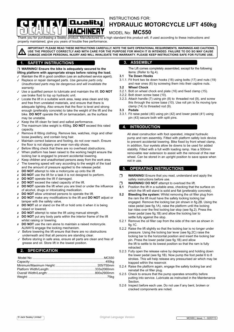
5. OPERATING INSTRUCTIONS WARNING! ensure that you read, understand and apply the safety instructions before use. WARNING! DO NOT attempt to overload the lift. 5.1 Position the lift in a suitable area, checking that the surface on which the lift will stand is solid and flat (preferably concrete).5.2 Bleeding the system: Whilst removing the oil filler plug from the ram the lift must have the safety locking locking bar engaged. Remove the locking bar pin shown in fig.2B. Using the raise pedal (see fig.1A), raise the platform until the locking bar rides over the first locking bar stop (see fig.2). Press the lower pedal (see fig.1B) and allow the locking bar to settle fully against the stop. 5.2.1 Remove the oil filler cap from the side of the ram as shown in fig.1C. 5.2.2 raise the lift slightly so that the locking bar is no longer under pressure. Using the locking bar lever (see fig.2C) raise the locking bar to the horizontal position and insert the locking bar pin. Press the lower pedal (see fig.1B) and allow the lift to settle to its lowest position so that the ram is fully retracted. 5.2.3 fully open the release valve by depressing and holding down the lower pedal (see fig.1B). Now pump the foot pedal 6 to 8 strokes. this will help release any pressurised air which may be trapped within the reservoir. 5.2.4 raise the platform again, engage the safety locking bar and reinstall the oil filler plug.5.2.5 check to ensure that the pump operates smoothly before putting into service. lubricate as instructed in the Maintenance section.5.2.6 Inspect before each use. do not use if any bent, broken or cracked components are noted.
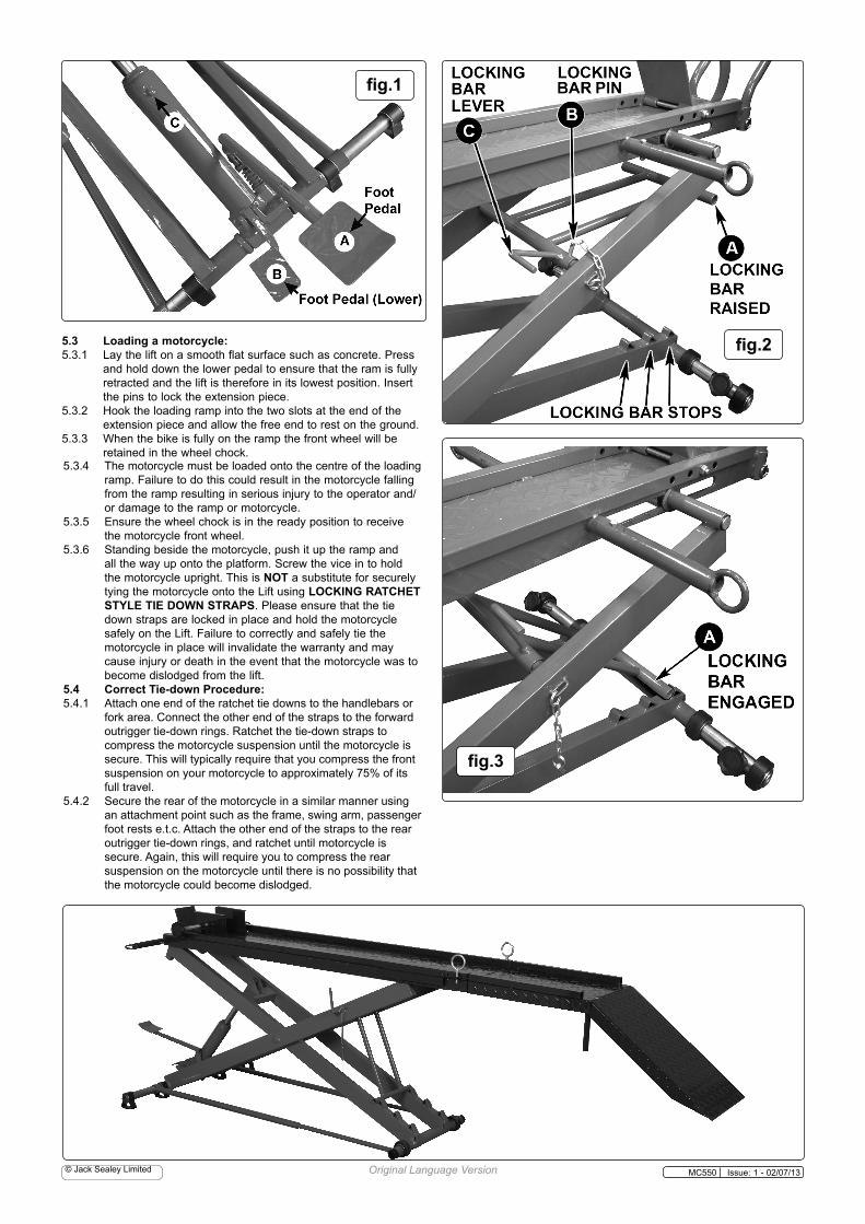
5.3 Loading a motorcycle: 5.3.1 lay the lift on a smooth flat surface such as concrete. Press and hold down the lower pedal to ensure that the ram is fully retracted and the lift is therefore in its lowest position. Insert the pins to lock the extension piece.5.3.2 Hook the loading ramp into the two slots at the end of the extension piece and allow the free end to rest on the ground.5.3.3 When the bike is fully on the ramp the front wheel will be retained in the wheel chock. 5.3.4 the motorcycle must be loaded onto the centre of the loading ramp. failure to do this could result in the motorcycle falling from the ramp resulting in serious injury to the operator and/ or damage to the ramp or motorcycle.5.3.5 ensure the wheel chock is in the ready position to receive the motorcycle front wheel.5.3.6 standing beside the motorcycle, push it up the ramp and all the way up onto the platform. screw the vice in to hold the motorcycle upright. this is NOT a substitute for securely tying the motorcycle onto the lift using LOCKING RATCHET STYLE TIE DOWN STRAPS. Please ensure that the tie down straps are locked in place and hold the motorcycle safely on the lift. failure to correctly and safely tie the motorcycle in place will invalidate the warranty and may cause injury or death in the event that the motorcycle was to become dislodged from the lift.5.4 Correct Tie-down Procedure:5.4.1 Attach one end of the ratchet tie downs to the handlebars or fork area. connect the other end of the straps to the forward outrigger tie-down rings. ratchet the tie-down straps to compress the motorcycle suspension until the motorcycle is secure. this will typically require that you compress the front suspension on your motorcycle to approximately 75% of its full travel.5.4.2 secure the rear of the motorcycle in a similar manner using an attachment point such as the frame, swing arm, passenger foot rests e.t.c. Attach the other end of the straps to the rear outrigger tie-down rings, and ratchet until motorcycle is secure. Again, this will require you to compress the rear suspension on the motorcycle until there is no possibility that the motorcycle could become dislodged.
Original Language Version Mc550 Issue: 1 - 02/07/13© Jack sealey limited
fig.3
fig.1
fig.2
fig.55.5 Raising the lift. CAUTION: DO NOT insert any body parts (e.g., fingers, arms, etc.) within the interior frame of the Lift while raising or lowering the Lift.5.5.1 With the motorcycle tied down securely on the lift, ensure that the locking bar pin is removed (see fig.2B) so that the safety locking bar is free to move. see fig.3.5.5.2 there are three preset heights for the lift depending on which stop the safety locking bar is engaged at (see fig.2). Pump the foot pedal until the safety locking bar rides over the chosen stop position and drops back onto the frame.5.5.3 Now press the lower pedal (see fig.2B) to allow the lift to drop slightly so that the safety locking bar is firmly up against the chosen stop position.5.6 Lowering the lift.5.6.1 Pump the foot pedal to raise the lift slightly so that the safety locking bar is no longer pressing against the stop.5.6.2 raise the safety locking bar using lever 'c' in fig.2 and lock it in place with the locking bar pin. (See fig.2B)5.6.3 Before lowering the lift ensure that there is nothing within the lift frame that could be damaged by the scissor action of the descending lift. Ensure that no body parts such as hands, arms, legs or feet are within the interior frame of the lift.5.6.4 to lower the lift operate the slow descent pedal and allow the lift to settle to its lowest position in preparation for removing the motorcycle. 5.7 Removing the motorcycle from the wheel vice.5.7.1 With the tie-down straps removed, push down on the handle bars of your motorcycle, slightly compressing the front suspension of the motorcycle.5.7.2 Pull up and back on the motorcycle handlebars.5.7.3 Keeping your hands on the handlebar, pull the motorcycle backwards off the lift.
5.8 Storing the lift vertically.5.8.1 the lift can be stored vertically. o WARNING: In this position the lift is not free standing and must be secured to a wall using a strong chain and a secure fixing. Failure to adequately secure the lift could result in serious injury or death in the event of the lift falling over.5.8.2 With the lift in its lowest position remove the ramp from the end of the extended platform. thread the velcro strap through the guides on the sides of the lift and secure it around the lift to ensure its stays folded whilst it is being lifted to the vertical position.5.8.3 The lift must be raised by two people and will stand on the two legs and pedal on the wheel chock end. Whilst one person continues to support the lift the other will secure it in position using the chain.5.9 Putting the lift back down for use.5.9.1 When returning the lift to the horizontal position, equal care is required to avoid injury to persons. At least two people should be on hand to support the lift as it is put down for service.
Original Language Version Mc550 Issue: 1 - 02/07/13© Jack sealey limited
fig.4
IMPORTANT: NO RESPONSIBILITY IS ACCEPTED FOR INCORRECT USE OF THE LIFT.Hydraulic products are repaired by local service agents only. We have service/repair agents in all parts of the uK. DO NOT return the product to us. Please call us on 01284 757500 to obtain the address and telephone number of your local agent. If the product is under guarantee please contact your dealer.De-commissioning: should the lift become completely unserviceable, draw off the oil into an approved container and dispose of the lift and the oil according to local regulations.
6.1. When the lift is not in use, it must be returned to its lowest position to minimise ram and piston corrosion. 6.2. Keep the lift clean and wipe off any oil or grease. lubricate all moving parts.. 6.3. Before each use check all parts. If any part of the lift is damaged or suspect, remove lift from service and take necessary action to repair. DO NOT use the lift if it is believed to have been subjected to abnormal load or shock. Inspect and take appropriate action.6.4. Periodically check the ram and piston for signs of corrosion. clean exposed areas with a clean oiled cloth.6.5 Topping up or changing the oil.6.5.1 to top up or change the oil the ram has to be removed from the lift. WARNING! only a good quality hydraulic oil, such as seAley HydrAulIc oIl, must be used. DO NOT use brake fluid, transmission fluid or motor oil. use of improper fluid can cause premature failure of the lift and the potential for sudden and immediate loss of load. IMPORTANT!: only fully qualified personnel should attempt maintenance or repair. contact your authorised dealer.6.5.2 set the lift in the upright position and secure it against falling, ensuring that you have access to the ram on the underside of the lift. 6.5.3 disconnect the two linkages attached to the ram. remove the circlips from pivot pins at either end of the ram. remove upper pivot pin. support ram, remove lower pivot pin and remove ram.6.5.4 With the ram in the upright position remove the filler plug and top up to the level of the filler hole. replace the plug.6.5.5 to change the oil lay the ram on its side and drain the oil into a suitable container.6.5.6 set the ram in the upright position and refill to the level; of the filler hole. replace the plug.6.5.7 Install the ram back into the lift by reversing the steps in section 6.5.3.
6. MAINTENANCE 7. TROUBLESHOOTING
SYMPTOM POSSIBLE CAUSE SOLUTIONJack will not lift load.
release valve not tightly closed.
close release valve fully.
overload condition. remove/reduce load
Hydraulic unit malfunction
service hydraulic unit
Jack will lift but not retain pressure
release valve not tightly closed.
close release valve fully.
overload condition. remove/reduce load
Hydraulic unit malfunction
service hydraulic unit
Jack will lift not lower after unloading
Reservoir overfilled Drain fluid to correct level
linkages binding clean & lubricate moving parts
Poor lift performance
fluid level low Ensure proper fluid level
Air trapped in system Bleed system
Poor lift performance
fluid level low top up to correct level
Air trapped in system Bleed system
Will not lift to full extension
fluid level low Ensure proper fluid level
NOTE: It is our policy to continually improve products and as such we reserve the right to alter data, specifications and component parts without prior notice.IMPORTANT: no liability is accepted for incorrect use of this product. WARRANTY: Guarantee is 12 months from purchase date, proof of which will be required for any claim. INFORMATION: for a copy of our latest catalogue and promotions call us on 01284 757525 and leave your full name and address, including postcode.
01284 757500
01284 703534 [email protected]
Sole UK Distributor, Sealey Group, Kempson Way, suffolk Business Park, Bury st. edmunds, suffolk,IP32 7Ar
www.sealey.co.ukW e b
Original Language Version Mc550 Issue: 1 - 02/07/13
Environmental Protection. recycle unwanted materials instead of disposing of them as waste. All tools, accessories and packaging should be sorted, taken to a recycle centre and disposed of in a manner which is compatible with the environment.
© Jack sealey limited
Parts support is available for this product. to obtain a parts listing and/or a diagram please log on to: www.sealey.co.uk, email: [email protected] or phone: 01284 757500