instructions for installation and …...turbomax vuw 242/1 e turbomax vuw 282/1 e wall hung room...
TRANSCRIPT

TURBOmax VUW 242/1 E
TURBOmax VUW 282/1 E
Wall hung room sealed fan assistedcombination boilers
INSTRUCTIONS FOR INSTALLATION AND SERVICING
HEATING, CONTROLS, HOT WATER.

2
Page 1. Introduction 3
2. Boiler Specification 42.1 Technical Data 42.2 Dimensions 52.3 Boiler connections 52.4 Function diagram 6
3. General Requirements 73.1 Related documents 73.2 Boiler location 73.3 Gas supply 83.4 Flue system 83.5 Air supply 103.6 Electricity supply 103.7 Guide to system requirements 10
4. Boiler installation sequence 134.1 General 134.2 Boiler delivery 134.3 Preparation of boiler location 144.4 Installing the flue system 164.5 Mounting the boiler 164.6 Connecting the flue assembly
to the boiler 174.7 Electrical installation 194.8 Controls 20
5. Commissioning 225.1 Preliminary electrical checks 225.2 Gas supply 225.3 Water supply 225.4 Filling the heating system 235.5 Initial system flush ('cold') 235.6 Initial lighting 245.7 Gas inlet working pressure 255.8 Main burner pressure 255.9 Adjusting central heating
output (range rating) 265.10 Functional checks 275.11 Checking flame
supervision device 285.12 Final system flush ('hot') 285.13 Fitting case 285.14 Handing over to user 29
Page6. Servicing 296.1 Initial inspection 296.2 Routine maintenance 306.3 Re-commissioning the boiler 31
7. Parts replacement 327.1 Initial preparation 327.2 Fan 347.3 Air pressure switch 347.4 Burner 357.5 Electrodes 357.6 Temperature sensor (NTC) 367.7 Gas valve 367.8 Main Heat exchanger 377.9 CH expansion vessel 387.10 Transformer 397.11 Overheat thermostat 397.12 Pump 397.13 Automatic air release 407.14 Automatic bypass 407.15 Diverter valve 407.16 Pressure and temperature
gauge 417.17 Differential pressure switch 417.18 DHW microswitch 427.19 DHW heat exchanger 427.20 Circuit boards 43
8. Fault finding 448.1 Introduction 448.2 Logical fault finding procedure 448.3 Fault finding charts 45
9. Electrical diagrams 549.1 Functional flow diagram 549.2 Wiring diagram 559.3 Schematic appliance
circuit diagram 56
10. Short parts list 57
11. Supplementary LPG information 59
Leave these instructions with the userwhen the installation is completed.
33
1. Introduction Note: This boiler must be installedand serviced by a competent personin accordance with the Gas Safety(Installation and Use) Regulations1994. In the UK 'CORGI' RegisteredInstallers undertake the work to asafe and satisfactory standard.
The TURBOmax is a fullyautomatic, wall mounted, room sealedcombination boiler for central heatingand domestic hot water. Domestic hotwater is supplied directly from theboiler, without requiring a coppercylinder, cold water tank, feed andexpansion tank or associatedpipework. Domestic hot water haspriority over central heating.
The boiler has been designed for usewith a sealed central heating system,and comes fully tested and assembledwith a built-in circulating pump,bypass, expansion vessel and divertervalve.
TURBOmax boilers carry 'CE' Mark.This demonstrates that the boilers fulfillthe essential requirements of the GasAppliance Directive (90/396/EEC)and the Gas Appliance (Safety) Regulations 1992.
The 'CE' Mark also demonstrates thatthe boilers comply with therequirements of the ElectromagneticCompatibility Directive (Directive89/336/EEC), the Low Voltage Directive (73/23/EEC), the Boiler Efficiency Directive (92/42/EEC) andthe Boiler (Efficiency) Regulations1993.
TURBOmax meets the requirements ofStatutory Instrument ‘The Boiler (Effi-ciency) Regulations 1993 and therefore is deemed to meet the requirements of Directive 92/42/EECon the efficiency requirements for newhot-water boilers fired with liquid orgaseous fuels.
The TURBOmax range consists ofmodels with outputs for domestic hotwater of 24 and 28 kW. The boiler iseasily sited on any internal wall andcan be installed with either a horizontalor vertical RSF (Room Sealed Fanassisted) flue. Flue extensions andadditional bends and elbows areavailable for increased siting flexibility.(The boiler is not suitable for externalinstallation).
If desired an inhibitor may be used inthe system. Guidance on the use of inhibitors is contained in theseinstructions.
Natural Gas and LPG versions of theboiler are available.
The boiler contains a domestic hotwater heat exchanger. The temperaturein the heat exchanger is limited by theboiler control system and it is notnecessary to install a scale reducer onthe cold mains inlet to the boiler.However, in exceptionally hard waterareas to prevent scale formation in theproperty hot water systempipework, a scale reducer may befitted.
The TURBOmax has built-in diagnosticindicator lights which illuminate insequence giving information on theboiler status when operating and per-formance of key components to aid incommissioning and fault finding.
The data badge is fitted on the bottomof the combustion chamber.
See text of General Requirements forInstallation Requirements or notes.
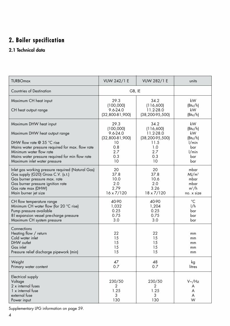
TURBOmax VUW 242/1 E VUW 282/1 E units
Countries of Destination GB, IE
Maximum CH heat input 29.3 34.2 kW(100,000) (116,600) (Btu/h)
CH heat output range 9.6-24.0 11.2-28.0 kW(32,800-81,900) (38,200-95,500) (Btu/h)
Maximum DHW heat input 29.3 34.2 kW(100,000) (116,600) (Btu/h)
Maximum DHW heat output range 9.6-24.0 11.2-28.0 kW(32,800-81,900) (38,200-95,500) (Btu/h)
DHW flow rate @ 35 °C rise 10 11.5 l/minMains water pressure required for max. flow rate 0.8 1.0 barMinimum water flow rate 2.7 2.7 l/minMains water pressure required for min flow rate 0.3 0.3 barMaximum inlet water pressure 10 10 bar
Inlet gas working pressure required (Natural Gas) 20 20 mbarGas supply (G20) Gross C.V. (s.t.) 37.8 37.8 MJ/m3
Gas burner pressure max. rate 10.0 10.6 mbarGas burner pressure ignition rate 2.0 2.0 mbarGas rate max (DHW) 2.79 3.26 m3/hMain burner jet size 16 x 7/120 18 x 7/120 no. x size
CH flow temperature range 40-90 40-90 °CMinimum CH water flow (for 20 °C rise) 1,032 1,204 l/hPump pressure available 0.25 0.25 bar8 l expansion vessel pre-charge pressure 0.75 0.75 barMaximum CH system pressure 3.0 3.0 bar
ConnectionsHeating flow / return 22 22 mmCold water inlet 15 15 mmDHW outlet 15 15 mmGas inlet 15 15 mmPressure relief discharge pipework (min) 15 15 mm
Weight 47 48 kgPrimary water content 0.7 0.7 litres
Electrical supplyVoltage 230/50 230/50 V~/Hz2 x internal fuses 2 2 A1 x internal fuse 1.25 1.25 Aexternal fuse 3 3 APower input 130 130 W
4
2. Boiler specification2.1 Technical data
Supplementary LPG information on page 59.
55
1021
880
95.5
480
120 max. 995* max. 995 *
1a
1a
190
1b
2
7 6 5 4 3 8
3550
380
120
GW
547
/1
fig. 1
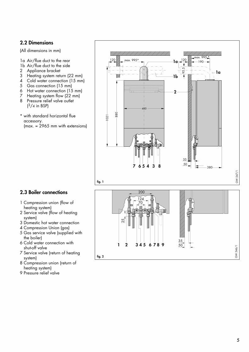
2.3 Boiler connections
1 Compression union (flow ofheating system)
2 Service valve (flow of heatingsystem)
3 Domestic hot water connection4 Compression Union (gas)5 Gas service valve (supplied with
the boiler)6 Cold water connection with
shut-off valve7 Service valve (return of heating
system)8 Compression union (return of
heating system)9 Pressure relief valve
200
124
5035
70
25
1 2 3 4 5 6 7 8 9
GW
546
/1
fig. 2
2.2 Dimensions(All dimensions in mm)
1a Air/flue duct to the rear1b Air/flue duct to the side2 Appliance bracket3 Heating system return (22 mm)4 Cold water connection (15 mm)5 Gas connection (15 mm)6 Hot water connection (15 mm)7 Heating system flow (22 mm)8 Pressure relief valve outlet
(3/4 in BSP)
* with standard horizontal flueaccessory.(max. = 2965 mm with extensions)
66
1
9
234
5
67 8
1
9
234
5
67 8
υ
0
0
6090
120
4
32
1
30
1
2
3
4
5
7
6
8
9
10
11
121314
15
33
32
31
30
29
28272625
24
23
22
2120
19
18
17
16
GW
573
/2G
B
fig. 3
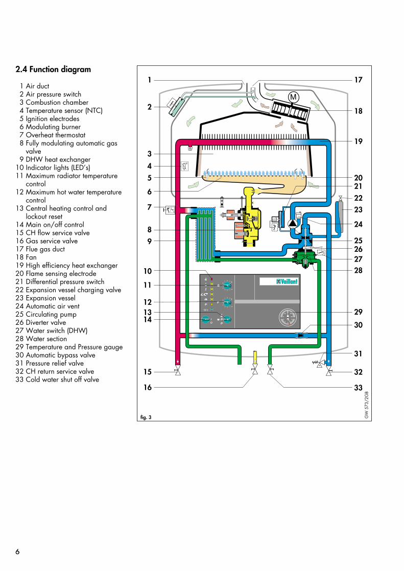
2.4 Function diagram
1 Air duct2 Air pressure switch3 Combustion chamber4 Temperature sensor (NTC)5 Ignition electrodes6 Modulating burner7 Overheat thermostat8 Fully modulating automatic gas
valve9 DHW heat exchanger
10 Indicator lights (LED’s)11 Maximum radiator temperature
control12 Maximum hot water temperature
control13 Central heating control and
lockout reset14 Main on/off control15 CH flow service valve16 Gas service valve17 Flue gas duct18 Fan19 High efficiency heat exchanger20 Flame sensing electrode21 Differential pressure switch22 Expansion vessel charging valve23 Expansion vessel24 Automatic air vent25 Circulating pump26 Diverter valve27 Water switch (DHW)28 Water section29 Temperature and Pressure gauge30 Automatic bypass valve31 Pressure relief valve32 CH return service valve33 Cold water shut off valve

7
3. General requirements 3.1 Related documentsThe installation of the boiler must bein accordance with the relevantrequirements of Gas Safety (Installationand Use) Regulations 1994, Healthand Safety Document No. 635 (TheElectricity at Work Regulations 1989),BS7671 (IEE Wiring Regulations) andthe byelaws of the local WaterUndertaking. It should also be inaccordance with the relevantrequirements of the Local Authority,Building Regulations, BuildingStandards (Scotland) Regulations andthe relevant recommendations of thefollowing British Standards:-
BS 5440: Flues and ventilation of gasfired boilers not exceeding 60 kW:- Part 1: Flues- Part 2: Ventilation
BS 5449: Specification for forcedcirculation hot water for domesticpremises.
BS 5546: Specification for gas hotwater supplies for domestic premises.
BS 6700: Services supplying waterfor domestic use within buildings andtheir curtilages.
BS 6798: Specification for installationof gas fired boilers not exceeding 60kW input.
BS 6891: Specification for installationof low pressure gas pipework up to28 mm (R1) in domestic premises (2ndfamily gas).
BS 7593: Treatment of water indomestic hot water central heatingsystems.
BRITISH GAS PUBLICATION DM2:Guide for Installation in TimberFramed Housing
Important
The appliance must be installed andserviced by a competent person asstated in the Gas Safety (Installationand Use) Regulations 1994
3.2 Boiler locationThe location chosen for the boiler mustpermit the provision of a satisfactoryflue termination. The location mustalso provide adequate space forservicing and air circulation aroundthe boiler. The boiler may be installedin any room, although particularattention is drawn to the requirementsof BS7671 (I.E.E. Regulations) and, inScotland, the electrical provisions ofthe Building Standards (Scotland)Regulations, in respect of the installationof a boiler in a room containing abath or shower.
(Note: Where a room sealed boileris installed in a room containing abath or shower, any electrical switchor boiler control utilising mainselectricity should be so situated that itcannot be touched by a person usingthe bath or shower).
Where the installation of the boilerwill be in an unusual location, specialprocedures may be necessary and BS5546 and BS 6798 give detailedguidance on this aspect.
The boiler must be mounted on a flat,vertical wall, which must be sufficientlyrobust to take the weight of the boiler.The boiler may be installed on acombustible wall, subject to therequirements of the Local Authoritiesand Building Regulations.
A compartment used to enclose theboiler must be designed andconstructed specifically for thispurpose. (An existing cupboard orcompartment may be used providedthat it is modified for the purpose).Details of essential features ofcupboard/compartment designincluding airing cupboard installationsare given in BS 6798.
If the boiler is to be fitted in a timberframed building, it should be fitted inaccordancewith British Gas PublicationDM2 'Guide for Gas Installations inTimber Framed Housing'.

8
3.3 Gas supplyThe gas supplier should ensure theavailability of an adequate supply ofgas.
A gas meter may only be connectedto the service pipe by the supplier ofgas or their contractor.
An existing meter should be checkedto ensure that it is capable of passingthe rate of gas supply required.
Installation pipes should be fitted inaccordance with BS 6891.
Pipework from the meter to the boilermust be of an adequate size. Do notuse pipes of a smaller size than theboiler gas connection (15 mm).
The complete installation must betested for soundness and purged asdescribed in BS 6891.
3.4 Flue systemThe standard horizontal flue system(Art. No. 300 807) is suitable forinstallations up to 995 mm measuredfrom the centre of the boiler flue outletto the outside face of the wall (A, fig.4). Flue extensions (Art. No. 300 802)are available to extend this length upto 2965 mm. Both 90° elbows(Art. No. 300 808) and 45° bends(Art. No. 300 809) are also availableto increase siting flexibility.
A vertical flue system is also available(Art. No. 300 800).
TURBOmax boilers may also be usedin SE- duct applications (SE- duct fluesystem available Art. No. 300810)
Refer to the flue installation instructionsfor full details.
A max = 2965 mm
GW
579
/2
fig. 4

3.4.1 Flue Termination
1. The terminal must be positionedsuch that the combustion products candisperse freely at all times.
2. In certain weather conditions aplume of water vapour may be visiblefrom the flue terminal. Positions wherethis could be a nuisance should beavoided.
3. If the terminal is fitted less than 2mabove a balcony, above ground orabove a flat roof to which peoplehave access, then a suitable guardmust be provided and fitted (availablefrom Tower Flue Components,Tonbridge, TN9 1TB: reference TFCtype K3).
Table 1:Terminal position for fan-assisted flue(minimum distance - see fig. 5)
A- Directly below an openable mmwindow or other opening(e.g. air brick) 300
B- Below gutters, soil pipesor drain pipes 25
C- Below eaves 25D- Below balconies 25
(below car port roof 200)E- From vertical drain pipes
and soil pipes 25F- From internal or external
corners 25G-Above ground or balcony
level 300H- From a surface facing a
terminal 600I- From a terminal facing a
terminal 1200J- From an opening in a
car port (e.g. door, window)into a dwelling 1200
K- Vertically from a terminalon the same wall 1500
L- Horizontally from aterminal on the same wall 300
M-Distance from adjacentwall for Vertical Flue 500
9
A
BCD
A
G
H, IF J
B F M
L
LK
K
G
G
F F
E
fig. 5 GW
595
/1
Where a terminal is fitted less than1m below a plastic gutter or less than0.5 m below painted eaves or anyother painted surface then a suitableshield at least 1m long should befitted to protect the surface.
Note: Vertical flues must not terminatewithin 600 mm of an openablewindow, air vent or any otherventilation opening.

10
3.5 Air supplyDetailed recommendations for airsupply are given in BS 5440: Part 2.
It is not necessary to have an air ventin the room or internal space in whichthe boiler is installed.
3.5.1 Cupboard or compartment airsupply
TURBOmax Room Sealed CombinationBoilers are very high efficiencyappliances.As a consequence the heat loss fromthe appliance casing during operationis very low. For cupboard andcompartment installations it is thereforenot necessary to provide any high orlow level permanent air vents forcooling purposes.
3.6 Electricity supplyA 230 V~ 50Hz single phaseelectricity supply fused to 3 amps mustbe provided in accordance with thelatest edition of BS7671 (I.E.E. WiringRegulations) and any other localregulations that may apply.
THIS APPLIANCE MUST BE EARTHED.The method of connection to the mainselectricity supply must provide ameans of completely isolating theboiler and its ancillary controls.Isolation is preferably by the use of afused three pin plug and unswitchedshuttered socket outlet, both complyingwith the requirements of BS 1363.Alternatively, a 3 Amp fuseddouble-pole switch with a 3mmcontact separation on both poles maybe used.
3.7 Guide to systemrequirements
3.7.1 Water circulation system
Detailed recommendations for thewater circulation system are given inBS 6798 and BS 5449: Part 1 (forsmall bore and micro bore centralheating systems).
Pipework not forming part of the usefulheating surface should be insulated tohelp prevent heat loss and possiblefreezing, particularly where pipes arerun through roof spaces and ventilatedunderfloor spaces.
Draining taps must be located inaccessible positions which permit thedraining of the whole system includingthe boiler and the hot water system.Draining taps should be at least 1/2in. BSP nominal size and be inaccordance with BS 2879.
The boiler is suitable for use withminibore or microbore systems.Copper tubing to BS 2871: Part 1should be used for water carryingpipework. All capillary joints in theDHW pipework must be made withlead free solder.
Particularly where a new boiler is tobe fitted to an existing system, it isgood practice that the system isthoroughly cleansed. This cleasingshould take place prior to the fitting ofthe new boiler and be in accordancewith BS 7593.
For advice on the application ofsystem cleansers contact Sentinel,Grace Dearborn Ltd, Widnes, Cheshire, WA8 8UD.Tel: 0151 4951861.

11
Heatingcircuitreturn Double check
valve assembly Hoseunions
TemporaryHose
Testvalve
Stopvalve
Mainswatersupply
fig. 6 GW
400
/1
3.7.2 Filling and make up
The system should be filled with watervia a separate filling point fitted at aconvenient position on the heatingcircuit. Where local Water AuthorityRegulation allows, a temporaryconnection to the mains may be used(fig. 6). The connection must beremoved when filling is completed.Where local Water AuthorityRegulation does not allow temporaryconnection, a sealed system fillerpump with break tank must be used.The heating system will not be filledautomatically from the domestic hotwater side.(Alternative methods of filling sealedsystems are given in BS 5449).
3.7.3 Pressure relief valve
A pressure relief valve is providedready assembled within the boiler(5, fig. 7). This safety device isrequired on all sealed C.H. systemsand is pre-set at 3 bar and providedwith a 3/4 in. BSP connection for adischarge pipe, which must be of noless than 15 mm diameter.
3.7.4 Pressure and temperature gauge
This is factory fitted to the boiler andindicates the primary circuit pressureto facilitate filling and testing, as wellas showing the temperature of thecentral heating system water.
11
8
1
410
7
9
5
6
2
3
fig. 7 GW
609
/1

12
Safety valve setting (bar) 3.0
Initial system pressure (bar) 1.0 1.5
Total water content of system VESSEL VOLUME (L)
litres25 2.7 3.950 5.4 7.8
100 10.9 15.6125 13.6 19.5150 16.3 23.4175 19.1 27.3200 21.8 31.2225 24.5 35.1250 27.2 39.0275 30.0 42.9300 32.7 46.8325 35.7 50.7350 38.1 54.6375 40.9 58.5400 43.6 62.4425 46.3 66.3450 49.0 70.2475 51.8 74.1500 54.5 78.0
For system volumes other thanthose given above, multiply 0.109 0.156the system volume by the factoracross
13,3 400ft mbar
10 300
6,7 200
3,3 100
00 200 400 600 800 1000 1200 1400 1600 l/h
Q
fig. 8 GW
402
/2
3.7.5 Expansion vesselAn expansion vessel is incorporatedinto the boiler suitable for a sealedheating system with a maximum watercontent of 100 litres.
If the nominal capacity of the built inexpansion vessel is not sufficient forthe heating system (for instance incase of modernisation of old opensystems) an additional expansionvessel can be installed external to theboiler. It should be fitted in the returnpipe as close as possible to the boilerin accordance with BS 5449: Part 1.Guidance on the sizing of anadditional expansion vessel is given inTable 2.
3.7.6 Circulating pump
The circulating pump is included in theboiler. The pump head available forthe heating system is shown in fig. 8.
3.7.7 System by-pass
An automatic system by-pass isincluded within the boiler. The boileris suitable for use in systems withthermostatic radiator valves and noadditional by-pass is required.
3.7.8 Venting
The boiler is fitted with an automaticair vent. Additional provision shouldbe made to enable the heating systemto be vented during filling andcommissioning either by automatic airvents or manually.
3.7.9 DHW expansion vesselaccessory
A DHW expansion vessel kit (Art. No.8070) is available as an optionalaccessory from Vaillant Ltd. Thisexpansion vessel kit should be fitted to the boiler whenever either a stopvalve of the loose jumper type or anon return valve are present in thecold water mains supply to the boiler(fig. 9).
Table 2: Sizing of Additional Expansion Vessel
D.H.W. expansion vessel fitted to the boiler
Non returnvalve
Stop valve
Mains watersupply
fig. 9 GW
494
/1
4. Boiler installationsequence
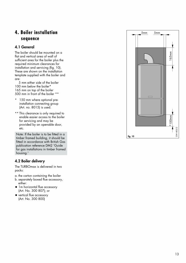
4.1 GeneralThe boiler should be mounted on aflat and vertical area of wall ofsufficient area for the boiler plus therequired minimum clearances forinstallation and servicing (fig. 10).These are shown on the installationtemplate supplied with the boiler andare:
5 mm either side of the boiler100 mm below the boiler*165 mm on top of the boiler500 mm in front of the boiler **
* 150 mm where optional pre- installation connecting group (Art. no. 8015) is used.
** This clearance is only required to enable easier access to the boiler for servicing and may be provided by an openable door, etc.
Note: If the boiler is to be fitted in atimber framed building, it should befitted in accordance with British Gaspublication reference DM2 'Guidefor gas installations in timber framedhousing.'
4.2 Boiler deliveryThe TURBOmax is delivered in twopacks:
a. the carton containing the boilerb. separately boxed flue accessory,
either:• 1m horizontal flue accessory
(Art. No. 300 807); or• vertical flue accessory
(Art. No. 300 800)
13
5mm 5mm
165m
m*1
00m
m
fig. 10 GW
403
/2
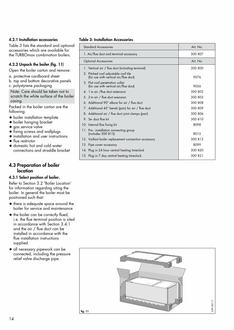
Standard Accessories Art. No.
1. Air/flue duct and terminal accessory 300 807
Optional Accessories Art. No.
1. Vertical air / flue duct (including terminal) 300 800
2. Pitched roof adjustable roof tile(for use with vertical air/flue duct) 9076
3. Flat roof penetration collar(for use with vertical air/flue duct) 9056
4. 1 m air /flue duct extension 300 802
5. 2 m air / flue duct exension 300 803
6. Additional 90° elbow for air / flue duct 300 808
7. Additional 45° bends (pair) for air / flue duct 300 809
8. Additional air / flue duct joint clamps (pair) 300 806
9. Se- duct flue kit 300 810
10. Internal flue fixing kit 8098
11. Pre - installation connecting group(includes 300 813) 8015
12. Vaillant boiler replacement connection accessory 300 813
13. Pipe cover accessory 8099
14. Plug in 24 hour central heating timeclock 300 820
15. Plug in 7 day central heating timeclock 300 821
14
4.2.1 Installation accessoriesTable 3 lists the standard and optionalaccessories which are available forthe TURBOmax combination boilers.
4.2.2 Unpack the boiler (fig. 11)Open the boiler carton and remove:a. protective cardboard sheetb. top and bottom decorative panels c. polystyrene packagingNote: Care should be taken not toscratch the white surface of the boilercasing.
Packed in the boiler carton are thefollowing:
• boiler installation template• boiler hanging bracket• gas service valve• fixing screws and wallplugs• installation and user instructions• flue restrictor• domestic hot and cold water
connections and straddle bracket
4.3 Preparation of boilerlocation
4.3.1 Select position of boiler.Refer to Section 3.2 'Boiler Location'for information regarding siting theboiler. In general the boiler must bepositioned such that:
• there is adequate space around theboiler for service and maintenance
• the boiler can be correctly flued,i.e. the flue terminal position is sitedin accordance with Section 3.4.1and the air / flue duct can beinstalled in accordance with theflue installation instructions supplied.
• all necessary pipework can beconnected, including the pressurerelief valve discharge pipe.
fig. 11 GW
601
/1
Table 3: Installation Accessories

15
4.3.2 Using the boiler template(fig. 12)
4.3.2.1 Once a suitable location hasbeen chosen, fix the paper installationtemplate on the wall ensuring that thecenterline of the template is verticalusing a spirit level or plumb line.The template shows the positions ofthe fixing holes for the boiler hangingbracket (2) and the optionalpre-installation connection group (3).The template also shows the positionof the flue exit hole, for use where theair flue duct is to be installed directlyto the rear of the boiler, e.g. wherethe boiler is installed on an outsidewall and the flue terminates directlybehind.4.3.2.2 A Pre - installation connectiongroup (Art. No. 8015) is available asan optional accessory. It is used toallow the installation of the centralheating and domestic hot waterpipework without the need to have theboiler in position. Where an oldexisting Vaillant boiler is to bereplaced, the boiler replacementaccessory (Art. No. 300 813) can beused to allow easy connection on thenew boiler to the existing connectinggroup. Refer to the instructionssupplied separately with theseaccessories.4.3.2.3 Mark on the wall the positionsof the hanging bracket fixing holes (2).Drill two holes Ø10 mm for the hanging bracket. (Note: Use thealternative fixing holes wherenecessary).4.3.2.4 Rear exit flue.Mark the position of the centre of theflue duct and its circumference, e.g.by drilling through the template(1, fig. 12).4.3.2.5 Other flue options.Refer to the installation instructionssupplied with the flue accessory fordetailed instructions on other flueoptions such as vertical RSF flues, flueruns to the side of the boiler and theuse of additional flue elbows andbends etc.4.3.2.6 Remove the template from thewall and plug the drilled holes usingthe wallplugs supplied.
1
2
3
fig. 12 GW
426
/1
4.3.3 Fitting the boiler hangingbracket.
Secure the hanging bracket to the wall using the screws supplied. (If thecondition of the wall is poor it may be necessary to use additional oralternative fixings to ensure adequatesupport).
NOTE: If the boiler is to be fitted in atimber framed building ensure that thebrackets are secured to a substantialpart of the timber frame capable oftaking the weight of the boiler.
4.4 Installing the flue systemAt this stage install the flue system(refer to separate installationinstructions supplied).
4.5 Mounting the boiler4.5.1 Preparation Remove the boiler from the carton.Lay the boiler on the floor and remove the white boiler bottom coverby removing two screws (1, fig. 51)and slackening two screws (2, fig.51). Do not remove boiler sidepanels. Remove the two plastic sea-ling caps from the domestic waterconnections.Fit the pre-assembled cold water inletand hot water outlet pipes with straddle bracket (1,2,3, fig. 15) towater connections on boiler (4, fig.15) using washers provided.
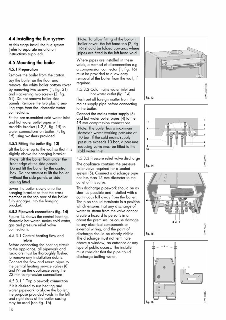
4.5.2 Fitting the boiler (fig. 13)Lift the boiler up to the wall so that it isslightly above the hanging bracket.Note: Lift the boiler from under thefront edge of the side panels.Do not lift the boiler by the controlbox. Do not attempt to lift the boilerwithout the side panels or side casing fitted.
Lower the boiler slowly onto thehanging bracket so that the crossmember at the top rear of the boilerfully engages into the hangingbracket.
4.5.3 Pipework connections (fig. 14)Figure 14 shows the central heating,domestic hot water, mains cold water,gas and pressure relief valveconnections.
4.5.3.1 Central heating flow andreturn
Before connecting the heating circuitto the appliance, all pipework andradiators must be thoroughly flushedto remove any installation debris.Connect the flow and return pipes tothe central heating service valves (8)and (9) on the appliance using the22 mm compression connections.
4.5.3.1.1 Top pipework connectionIf it is desired to run heating andwater pipework to above the boiler,the purpose provided voids in the leftand right sides of the boiler casingmay be used (see fig. 16).
Note: To allow fitting of the bottomboiler cover, the left hand tab (2, fig.16) should be folded upwards wherepipes are fitted in the left hand void.
Where pipes are installed in thesevoids, a method of disconnection e.g.a compression connector (1, fig. 16)must be provided to allow easyremoval of the boiler from the wall, ifrequired.
4.5.3.2 Cold mains water inlet andhot water outlet (fig. 14)
Flush out all foreign matter from themains supply pipe before connectingto the boiler.Connect the mains water supply (3)and hot water outlet pipes (4) to the15 mm compression connections.Note: The boiler has a maximumdomestic water working pressure of10 bar. If the cold mains supplypressure exceeds 10 bar, a pressurereducing valve must be fitted to thecold water inlet.
4.5.3.3 Pressure relief valve dischargeThe appliance contains the pressurerelief valve required for a sealedsystem (5). Connect a discharge pipenot less than 15 mm diameter to theoutlet of this valve.This discharge pipework should be asshort as possible and installed with acontinuous fall away from the boiler.The pipe should terminate in a positionwhich ensures that any discharge ofwater or steam from the valve cannotcreate a hazard to persons in orabout the premises, or cause damageto any electrical components orexternal wiring, and the point ofdischarge should be clearly visible.The discharge must not terminateabove a window, an entrance or anytype of public access. The installermust consider that the pipe coulddischarge boiling water.
16
fig. 13 GW
608
/1G
B
11
8
1
410
7
9
5
6
2
3
fig. 14 GW
609
/1
132
4
fig. 15 GW
706
/1
2
1
fig. 16 GW
100
1/1

4.5.3.4 Gas supply The boiler is supplied with a 20 x 15mm gas service valve (10, fig. 14). Fitthe 20 mm compression fitting to theboiler gas inlet (11, fig. 14) and tighten. Install a gas supply pipe notless than 15 mm diameter and connectto the gas service valve. (Ensure thegas supply pipework is adequatelysized such that a 20 mbar - (8" w.g.) -gas pressure is available at the boilerinlet at full flow rate). Tighten all unionconnections.
4.6 Connecting the flueassembly to the boiler
Note : A flue restrictor ring is sup-plied packed with the users andinstallation instructions. The restrictor should be used underthe following circumstances : -
Horizontal fluesWhere a horizontal flue less than 1 min length is used.(DO NOT fit the restrictor where thehorizontal flue is more than 1 m inlength).
Vertical fluesWhere a vertical flue less than 1 m (e.g. 1 m between the top of the boiler and the bottom of the vertical air / flue duct assemly) is used (DO NOT fit the restrictor where thevertical flue is more than 1 m inlength).
4.6.1 Horizontal FlueRemove two screws (1, fig. 18) andtake off one half ring (2, fig. 18). Ifnecessary, fit the flue restrictor ring(Note : It will be necessary to removeboth half rings if the flue restrictor ringis to be fitted. The flue restrictor ringshould be placed on top of flue outletdirectly below the two half rings seefig. 18a. One half ring should bereplaced immediately).Place a 63 mm diameter x 35 mmwide flue duct clamp (4, fig. 19)loosely over the flue duct (1, fig. 19).Place the 63 mm diameter x 25 mmwide flue duct clamp (5, fig. 19) overthe flue gas connection on the boiler.
17
3
2
1
fig. 18a GW
705
/1
1 2
fig. 18 GW
592
/1
5 4 1 2 3
fig. 19 GW
593
/1
34
5
6
1
2
fig. 17 GW
823
/1

Loosen screws on the 95 mm diameterx 55 mm wide clamp (6, fig. 21) andpush over the air duct.Remove screws and sealing washeron the 95 mm diameter x 25 mmwide clamp (3, fig. 21) and push ontothe flue elbow on the side to beconnected to the appliance. Ensurethe clamp is clear of the end of theelbow.Push the flue elbow into the clamp (2,fig. 20) connected to the applianceflue gas duct and tighten the securingscrews lightly.Ensure that the elbow and air/flueduct line up and are closely buttedtogether. Pull the clamp (4, fig. 20)over the joint between the flue gasduct and flue elbow. Ensure that theair/flue duct and terminal are correctlypositioned. Tighten the securing screwson both clamps.
Note : Excessive tightening of thesescrews is not necessary. Ensure thatthe air / flue duct and terminalassembly is not displaced though thewall. Check that the air duct of theterminal still projects by 90 mmthrough the wall.
Refit the half ring 2, fig. 21. Pull the95 mm diameter x 25 mm wideclamp (3, fig. 21) over the joint between the flue elbow and half rings.Refit the screws and sealing washerand tighten lightly.Pull the 95 mm diameter x 55 mmwide clamp (6, fig. 21) over the jointbetween the flue elbow and air/flueduct. Tighten the securing screws onboth clamps.Drill two holes, 3 mm diameterthrough both air duct clamps into theair ducts at the most convenient positions (5, fig. 21). Take care not topenetrate the inner flue duct. Screwthe clamps to the air ducts using theself tapping screws provided.
4.6.2 Vertical FlueRemove the two half rings (2, fig. 18)and, if necessary, fit the flue restrictorring. (Note: It will be necessary to removeboth half rings if the flue restrictor ringis to be fitted. The flue restrictor ringshould be placed on top of flue outletdirectly below the two half rings (seefig. 18A). One half ring should bereplaced immediately).Fit the 63 mm diameter x 68 mm wideflue duct sleeve (2, fig. 22) over theflue gas duct of the air/flue ductassembly.
Loosen the screws of the 95 mmdiameter x 55 mm wide clamp (1, fig.22) and push over the air duct of theair/flue duct assembly.Lower the flue assembly until a gap ofabout 25 mm exists between the airduct of the air/flue duct and terminalassembly and the half rings on theappliance. The two ducts must not butttogether.Pull the sleeve (2, fig. 22) down overthe flue connection of the applianceagainst the stop. Align the holes in thesleeve and boiler flue gas connectorand secure with a self tapping screw(1, fig.23).
Note : The sleeve must not be screwedto the bottom of the flue gas duct ofthe air/flue duct assembly. This ductmust be able to slide in order toabsorb small movements of the roofstructure.
Refit the two half rings. Pull the 95 mmdiameter x 55 mm wide clamp downover the joint between the air/flueduct assembly and the half rings. Tigh-ten the clamp screws (1, fig.24).
18
12
34
5 6 7
fig. 21
2 3 4 1
fig. 20 GW
616
/1G
W 5
94/1
3
1
2
fig. 22 GW
558
/1
1
232
fig. 24 GW
602
/1
1 2
fig. 23 GW
560
/1

Drill two holes 3 mm diameterthrough the air duct clamp (2. Fig 24)ensuring that the drill does not pene-trate the flue duct. Screw the clamp tothe boiler half ring using the self tap-ping screws provided.Note: The air duct clamp must not bescrewed to the bottom of the air flueduct and terminal assembly. Theair/flue duct and terminal assemblymust be able to slide in the air duct clamp to absorb any slightmovements in the roof structure.
4.7 Electrical installation4.7.1 General electrical requirementsAll electrical work shall be carried outby a competent person and shallcomply with BS7671 (IEE Regulations).The boiler is supplied for connectionto a 230V~ 50Hz supply fused at 3Arating. Connection to the mains supplyshould be made via a fused 3 pinplug to an unswitched, shutteredsocket, both complying with therequirements of BS1363. (Alternatively,connection may be made via a 3Amp fused double pole isolatorhaving a contact separation of at least3mm in all poles and supplying theboiler and controls only). The point of connection to the mainsmust allow complete electrical isolationof the boiler and its ancillary controls.It should be readily accessible andadjacent to the boiler. A 3 coreflexible cord according to BS6500tables 6, 8 or 16 (3x0.75 to 3x1.5mm2) should be used.Warning: This appliance must be
earthed4.7.2 Connecting to mains supplySlacken front panel fixing screw (1,fig. 25) and lower front panel. Removeterminal box cover by undoing screw(1, fig. 26)Connect the power supply cord asfollows (see fig. 27):-green / yellow (earth) wire....
boiler terminal Blue (neutral) wire..... boiler terminal NBrown (live) wire..... boiler terminal LNote: Do not use boiler terminal
connections 7-8-9
19
1 2
fig. 25 GW
603
/1
1 3
2fig. 26 GW
614
/1
NL345
789
1
2
fig. 27 GW
152
8/0G
B
1
fig. 28 GW
152
7/0
IMPORTANT Ensure that all cordspass through the terminal box entrancegrommets and are securely fixed bythe cable clamps. Ensure that thepower supply cord is connected suchthat the current carrying conductorsbecome taut before the earthingconductor should the supply cord slipfrom the cable clamp.Refit the terminal box cover aftercompletion of all electrical components.
The cable clamp (1, fig. 28) is onlymeant as a mounting aid. A possibledamage caused when mounting orremoving it will not cause any malfunction of the appliance.
N L 4 3
N L 4 3
3 4 5
20
4 3 N L
N L 4
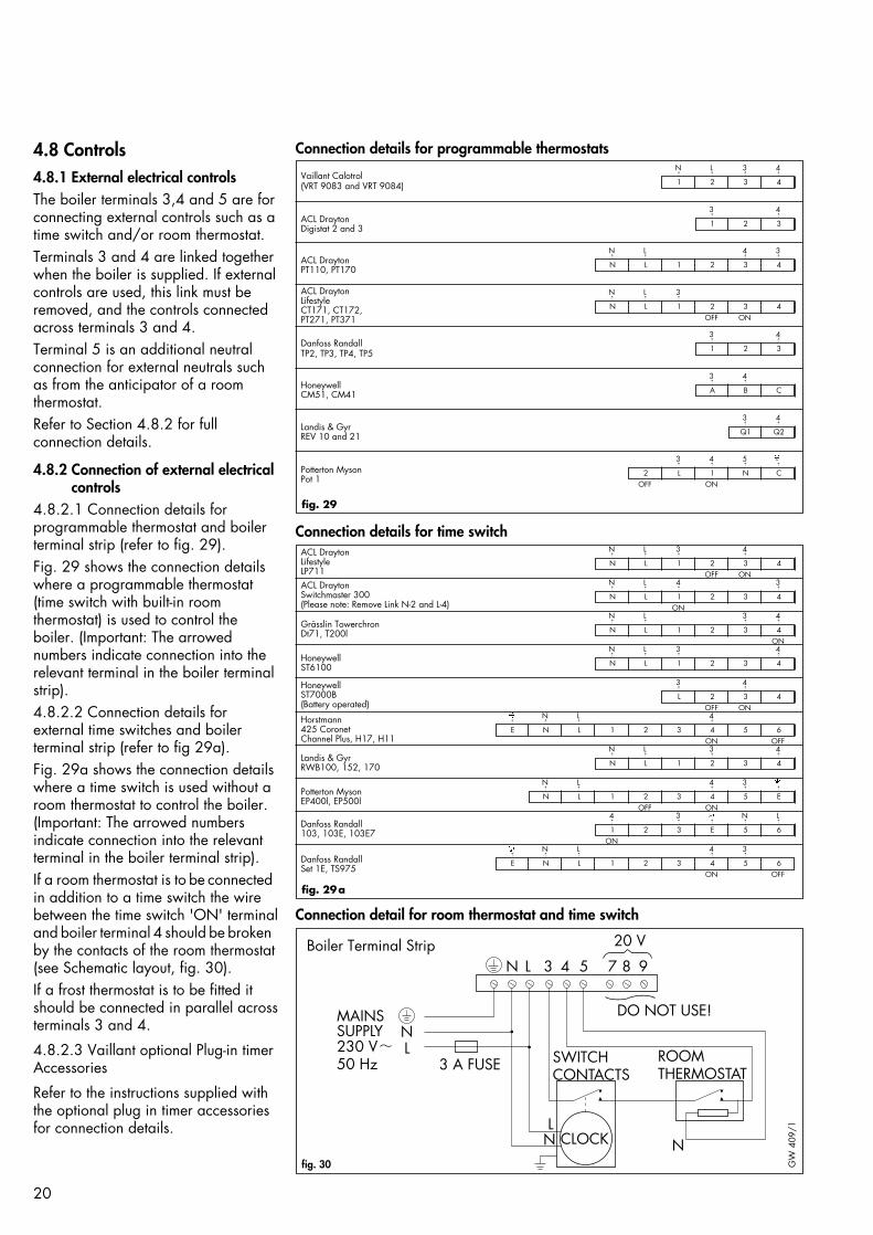
4.8 Controls4.8.1 External electrical controlsThe boiler terminals 3,4 and 5 are forconnecting external controls such as atime switch and/or room thermostat.Terminals 3 and 4 are linked togetherwhen the boiler is supplied. If externalcontrols are used, this link must beremoved, and the controls connectedacross terminals 3 and 4.Terminal 5 is an additional neutralconnection for external neutrals suchas from the anticipator of a roomthermostat.Refer to Section 4.8.2 for fullconnection details.
4.8.2 Connection of external electricalcontrols
4.8.2.1 Connection details forprogrammable thermostat and boilerterminal strip (refer to fig. 29).Fig. 29 shows the connection detailswhere a programmable thermostat(time switch with built-in roomthermostat) is used to control theboiler. (Important: The arrowednumbers indicate connection into therelevant terminal in the boiler terminalstrip).4.8.2.2 Connection details forexternal time switches and boilerterminal strip (refer to fig 29a).Fig. 29a shows the connection detailswhere a time switch is used without aroom thermostat to control the boiler.(Important: The arrowed numbersindicate connection into the relevantterminal in the boiler terminal strip).If a room thermostat is to be connectedin addition to a time switch the wirebetween the time switch 'ON' terminaland boiler terminal 4 should be brokenby the contacts of the room thermostat(see Schematic layout, fig. 30).If a frost thermostat is to be fitted itshould be connected in parallel acrossterminals 3 and 4.
4.8.2.3 Vaillant optional Plug-in timerAccessories
Refer to the instructions supplied withthe optional plug in timer accessoriesfor connection details.
�� � �
ACL DraytonLifestyle LP711ACL DraytonSwitchmaster 300(Please note: Remove Link N-2 and L-4)
Grässlin TowerchronDt71, T200l
HoneywellST6100
HoneywellST7000B(Battery operated)
Horstmann425 CoronetChannel Plus, H17, H11
Landis & GyrRWB100, 152, 170
Potterton MysonEP400l, EP500l
Danfoss Randall103, 103E, 103E7
Danfoss RandallSet 1E, TS975
fig. 29a
7543
MAINSSUPPLY230 V 50 Hz
L
L
L
N
N
N N
20 V
DO NOT USE!
3 A FUSE SWITCH CONTACTS
ROOM THERMOSTAT
CLOCK
8 9
fig. 30 GW
409
/1
Boiler Terminal Strip
E N L 1 2 3 4 5 6ON OFF
�� � �
E N L 1 2 3 4 5 6ON OFF
� �� ��
N L 1 2 3 4 5 EOFF ON
N L 3 4
���
���
��
��
N L 1 2 3 4
1 2 3 E 5 6ON
N L 3 4
� � � �
N L 1 2 3 4OFF ON
N L 4 3
� � � �
N L 1 2 3 4ON
N L 3 4� � � �
N L 1 2 3 4ON
N L 3 4
� � � �
N L 1 2 3 4
3 4� �
L 2 3 4OFF ON
Vaillant Calotrol(VRT 9083 and VRT 9084)
ACL DraytonDigistat 2 and 3
ACL DraytonPT110, PT170
ACL DraytonLifestyleCT171, CT172,PT271, PT371
Danfoss RandallTP2, TP3, TP4, TP5
HoneywellCM51, CM41
Landis & GyrREV 10 and 21
Potterton MysonPot 1
fig. 29
N L 4 3
� � � �
N L 1 2 3 4
N L 3
� � �
N L 1 2 3 4OFF ON
� � � �
2 L 1 N COFF ON
N L 3 4
� � � �
1 2 3 4
3 4
� �
1 2 3
3 4
� �
1 2 3
3 4
� �
A B C
3 4
� �
Q1 Q2
Connection detail for room thermostat and time switch
Connection details for time switch
Connection details for programmable thermostats

21
4.8.3 Thermostatic radiator valvesThe boiler has a built-in automaticbypass valve making it ideal for use insystems with thermostatic radiatorvalves (no separate system bypass isrequired).For optimum fuel economy it isrecommended that where TRVs areused they are used in conjunction witha programmable roomstat or separatetimer and room thermostat to ensurecomplete boiler shutdown when theheating demand is satisfied. (Theradiator in the room containing theroom thermostat should not be fittedwith a TRV).
4.8.4 Circulating pump The boiler incorporates a built-incirculating pump that is fullypre-wired. (No additional wiring isnecessary). The pump incorporates anautomatic overrun period after theboiler switches off.
4.8.5 Anti-cycling 'economiser' controlThe boiler incorporates a built inanti-cycling control to ensure thatenergy wasteful short cycling of theboiler cannot occur. This controlprevents the boiler from re-igniting fora pre-set period of 5 minutes aftercentral heating operation. (The hotwater operation is unaffected by thiscontrol and hot water can be drawnat any time).Note: To temporarily override theanti-cycling control, turn the mainon/off control to the ”off” position(0), and then back to the ”on”position (I) after a few seconds.
4.8.6 Frost protectionThe boiler has an internal frostthermostat which is designed for protection of the boiler.To protect remote or exposed parts ofthe heating system or property additional frost protection measuresmust be taken such as the installationof an external frost thermostat. Thisfrost thermostat should be connectedacross the boiler terminals 3 and 4, inparallel with any external heating controls.
22
3
1 2
fig. 31 GW
610
/1
5. Commissioning
5.1 Preliminary electrical checksCheck the electrical installation bycarrying out short circuit, earthcontinuity and resistance to earth testsand a check for correct polarity.
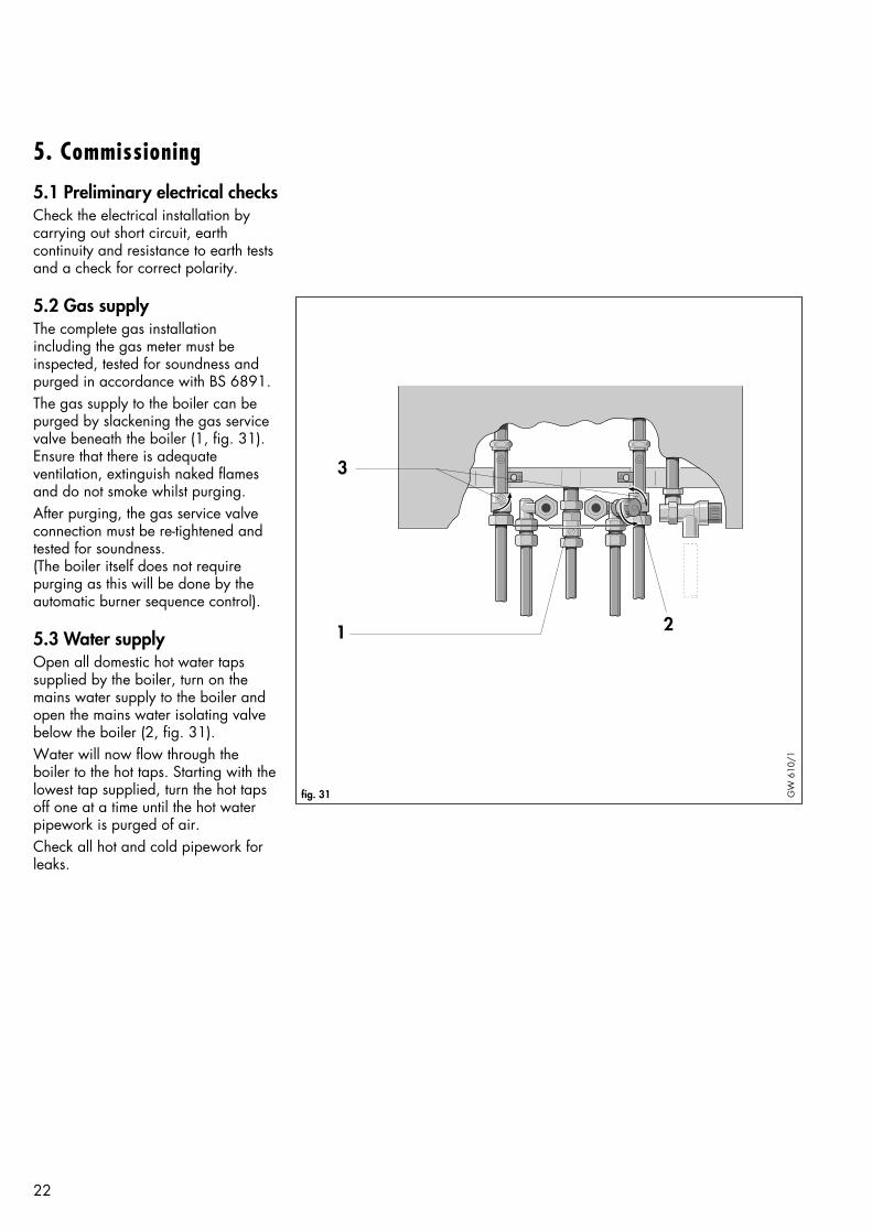
5.2 Gas supplyThe complete gas installationincluding the gas meter must beinspected, tested for soundness andpurged in accordance with BS 6891. The gas supply to the boiler can bepurged by slackening the gas servicevalve beneath the boiler (1, fig. 31).Ensure that there is adequateventilation, extinguish naked flamesand do not smoke whilst purging.After purging, the gas service valveconnection must be re-tightened andtested for soundness.(The boiler itself does not requirepurging as this will be done by theautomatic burner sequence control).
5.3 Water supplyOpen all domestic hot water tapssupplied by the boiler, turn on themains water supply to the boiler andopen the mains water isolating valvebelow the boiler (2, fig. 31).Water will now flow through theboiler to the hot taps. Starting with thelowest tap supplied, turn the hot tapsoff one at a time until the hot waterpipework is purged of air. Check all hot and cold pipework forleaks.
23
2
1
fig. 32 GW
634
/1
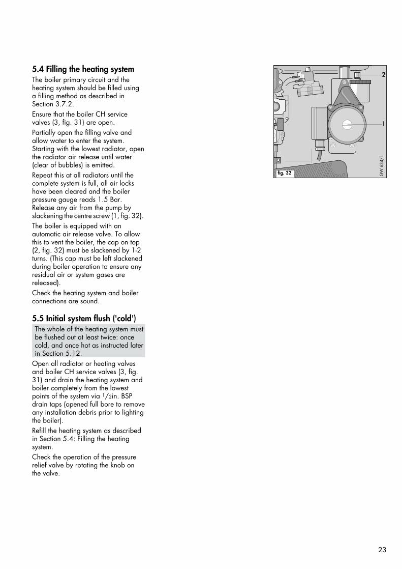
5.4 Filling the heating systemThe boiler primary circuit and theheating system should be filled usinga filling method as described inSection 3.7.2. Ensure that the boiler CH servicevalves (3, fig. 31) are open.Partially open the filling valve andallow water to enter the system.Starting with the lowest radiator, openthe radiator air release until water(clear of bubbles) is emitted. Repeat this at all radiators until thecomplete system is full, all air lockshave been cleared and the boilerpressure gauge reads 1.5 Bar.Release any air from the pump byslackening the centre screw (1, fig. 32).The boiler is equipped with anautomatic air release valve. To allowthis to vent the boiler, the cap on top(2, fig. 32) must be slackened by 1-2turns. (This cap must be left slackenedduring boiler operation to ensure anyresidual air or system gases arereleased).Check the heating system and boilerconnections are sound.
5.5 Initial system flush ('cold')The whole of the heating system mustbe flushed out at least twice: oncecold, and once hot as instructed laterin Section 5.12.
Open all radiator or heating valvesand boiler CH service valves (3, fig.31) and drain the heating system andboiler completely from the lowestpoints of the system via 1/2in. BSPdrain taps (opened full bore to removeany installation debris prior to lightingthe boiler).Refill the heating system as describedin Section 5.4: Filling the heatingsystem.Check the operation of the pressurerelief valve by rotating the knob onthe valve.

5.6 Initial lighting • Check that the boiler combustion
chamber (5, fig. 33) is correctlyfitted.
• Ensure the cold water shut-off valve(4, fig. 34) is open by turninganti-clockwise.
• Open the gas service valve (2, fig.34)
• Check that the CH service valves(1 and 5, fig. 34) are open.
• Check that all external heatingcontrols are calling for heat.
• Switch on the electricity supply tothe boiler.
• Set both the maximum hot watertemperature control (4, fig. 33) andmaximum radiator temperaturecontrol (3, fig. 33) to '9'.
• Turn the boiler on/off control (1,fig. 33) to the ”on” position ( ).
• Set the boiler central heatingcontrol (2, fig. 33) to the 'Heatingand Hot Water' position ( ).
The boiler will now operate for centralheating. Allow the boiler to run for afew minutes to clear any air remainingin the primary circuit.(If the boiler should fail to light afterthe 2nd ignition attempt the 'lock out'indicator will illuminate - see fig. 41.This usually means that the gas supplyis turned off, or is not purged of air.Check gas supply, and turn the centralheating control to the reset position - ( ) - and repeat lighting procedure).
• Set the boiler central heatingcontrol to the 'Hot Water only'position ( ). The boiler will now switch off.
• Reset the maximum radiator tempe-rature control to the required settingaccording to Section 5.14.
• FULLY open a hot water tap. Theboiler will now operate for hotwater.
24
7
1 2 4 3 6
5
fig. 33 GW
612
/13
4
5
6
1
2
fig. 34 GW
823
/1

VUW 242/1 VUW 282/1
Maximum Burner 10.0 mb 10.6 mbPressure (DHW) ( -–+1.0 mb) ( -–+1.0 mb)
Maximum Gas 2.79 m3/h 3.26 m3/hRate
(98.5 ft3/h) (115.1 ft3/h)
25
1
fig. 35 GW
635
/1
12
3
fig. 36 GW
153
3/0
1
2
3
fig. 37 GW
153
2/0
Table 4: Burner Pressure & Gas Rate
tolerance shown, contact VaillantLtd. Technical Department).
• Turn off the hot tap.• Remove U gauge. Tighten the sea-
ling screw (1, fig. 36)and test forsoundness. Reconnect NTC sensor(3, fig. 37). Refit plastic plug inchamber sensing tube.
• Reset the maximum hot watertemperature selector to the requiredsetting (see Section 5.14).
• Raise control box and secure inposition using screw (1, fig. 25).
At this point the preset maximumdomestic hot water flow rate can beadjusted if required.
Note: The water flow limiter builtinto the boiler ensures that themaximum domestic hot water flowrate does not exceed the nominalsetting (equivalent to a hot watertemperature rise of 35°C).Adjustment is only required if the userrequires a higher temperature risethan this setting.
Turn the water flow adjusting screw(1, fig. 35) clockwise to decrease theflow from the tap until the temperaturerise is at the desired level. Turn off thehot tap after completion of adjustment.
5.7 Gas inlet working pressureCheck the gas inlet working pressureby slackening the sealing screw andattaching a U gauge to the test point(3, fig. 36) on the inlet to the gas valve.Fire the boiler at full rate by openinga hot water tap. Check that the Ugauge is reading 20 mbar.(If the pressure is not 20mbar thisshould be investigated beforecontinuing with the commissioningprocedure. Lower pressures than20mbar are indicative of an incorrectlysized or partially blocked gas supply). Turn off the hot tap. Remove U gauge.Tighten the test point screw and testfor soundness.
5.8 Main burner pressureThe burner pressure on this boiler hasbeen factory set and does not requireadjustment. The main burner pressuremay be checked in the following way:
• Slacken the sealing screws andattach one arm of a U gauge to theburner test point (1, fig. 37). Remove plastic sealing plug andconnect the other arm to the combustion chamber sensing tube(2, fig. 36).
• Ensure the maximum hot watertemperature control (4, fig. 33) isset to '9'.
• Fully open a hot water tap to firethe boiler at full rate.Break the in line connector to theNTC temperature sensor (3, fig.37).
• Check that the burner pressure is asshown in Table 4. (If the burnerpressure is not correct within the
Output to Range rating mbarcentral Heating
mbar VUW 242/1 VUW 282/1
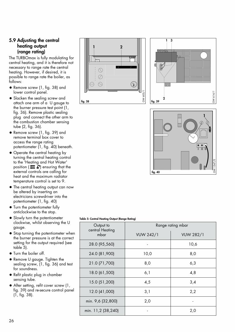
28.0 (95,560) - 10,6
24.0 (81,900) 10,0 8,0
21.0 (71,700) 8,0 6,3
18.0 (61,500) 6,1 4,8
15.0 (51,200) 4,5 3,4
12.0 (41,000) 3,1 2,2
min. 9,6 (32,800) 2,0 -
min. 11,2 (38,240) - 2,0
26
Table 5: Central Heating Output (Range Rating)
5.9 Adjusting the centralheating output(range rating)
The TURBOmax is fully modulating forcentral heating, and it is therefore notnecessary to range rate the centralheating. However, if desired, it ispossible to range rate the boiler, asfollows:
• Remove screw (1, fig. 38) andlower control panel.
• Slacken the sealing screw andattach one arm of a U gauge tothe burner pressure test point (1,fig. 36). Remove plastic sealingplug and connect the other arm tothe combustion chamber sensingtube (2, fig. 36).
• Remove screw (1, fig. 39) andremove terminal box cover toaccess the range ratingpotentiometer (1, fig. 40) beneath.
• Operate the central heating byturning the central heating controlto the 'Heating and Hot Water'position ( ) ensuring that theexternal controls are calling forheat and the maximum radiatortemperature control is set to 9.
• The central heating output can nowbe altered by inserting anelectricians screwdriver into thepotentiometer (1, fig. 40)
• Turn the potentiometer fully anticlockwise to the stop.
• Slowly turn the potentiometer clockwise, whilst observing the Ugauge.
• Stop turning the potentiometer whenthe burner pressure is at the correctsetting for the output required (seetable 5).
• Turn the boiler off.
• Remove U gauge. Tighten the sealing screw, (1, fig. 36) and testfor soundness.
• Refit plastic plug in chambersensing tube.
• After setting, refit cover screw (1,fig. 39) and re-secure control panel(1, fig. 38).
1 2
fig. 38 GW
603
/1
1 3
2fig. 39 G
W 6
14/1
1
fig. 40 GW
154
7/0

• The gas valve will open and spar-king will commence at the burner.The ignition indicator will illuminate.
• As soon as the burner has ignitedand the flame has been sensed theflame indicator will illuminate.
• By illuminating in this sequence theindicator lights have demonstratedcorrect operation of the boiler forCH.
Note : Should the boiler fail to lightit will attempt re-ignition after anapproximate delay of 10 seconds, ifthe boiler fails to light at the 2ndattempt the burner lock out indicatorwill illuminate. This usually meansthat the gas supply is turned off orhas not been purged of air. Checkthe gas supply, turn the central hea-ting control to the reset position ( )and repeat the lighting procedure.
0°C
3060
90
120
04
3 2 1bar
8 976
5
43 2 1
8 976
5
43 2 1
27
5.10 Functional Checks5.10.1 IntroductionThe Vaillant TURBOmax is equippedwith a set of diagnostic indicator lightsto show the operational status of theboiler. A functional check of DHWand CH operation can be made usingthese indicator lights (fig. 41).
5.10.2 Functional check of domestichot water
• Ensure that the power on indicatoris illuminated.
• Set the boiler central heatingcontrol to the 'Hot Water only'position ( ).
• Turn on a hot tap and draw waterat a high rate.
• The hot water demand indicatorwill illuminate.
• The appliance will start its lightingsequence. Once the fan and fluesystem has proved itself, the fanoperation indicator will light.
• The gas valve will open andsparking will commence at theburner. The ignition indicator willilluminate.
• As soon as the burner has ignitedand the flame has been sensed theflame indicator will illuminate.
• By illuminating in this sequence theindicator lights have demonstratedcorrect operation of the boiler forDHW.
5.10.3 Functional check of centralheating
• Ensure that the power on indicatoris illuminated.
• Set the boiler central heatingcontrol to the 'Central Heating andHot Water' position ( ).
• Ensure external controls are callingfor heat.
• The central heating demandindicator will illuminate.
• Providing the boiler has notachieved its set temperature, andthe anti cycling control is notactivated, the boiler will start itslighting sequence. Once the fanand flue system have proved theirsatisfactory operation the fanoperation indicator will light.
fig. 41 GW
849/
1
Burner lock out indicator
Flame indicator
Ignition indicator
Fan operation indicator
Central heating demand indicator
Hot water demand indicator
Power on indicator

28
5.11 Checking flamesupervision device
Operate the boiler and turn off thegas supply at the boiler gas servicevalve. The boiler should attempt to re-light (sparking at ignition electrodevisible through viewing window) forapproximately 9 seconds, if ignitiondoes not occur the boiler will re-attempt ignition after a further 10second delay before shutting down.The lock out indicator light will illuminate. Open the gas service valveand turn the central heating control (2, fig. 33) to the reset position ( ). Theboiler should now re-light.
5.12 Final system flush ('hot')Allow the boiler and system to reachmaximum temperature and check thatthe heating system is watertight. Turnthe boiler off and rapidly drain bothboiler and system while still hot.Refill the system and release all air asdescribed in Section 5.4. Releasewater from the system until the systemdesign pressure of 1.2 bar is attained.(The actual reading on the pressuregauge - (6, fig. 33) - should ideally be0.5 Bar plus an additional pressurecorresponding to the highest point ofthe system above the base of theboiler - 10 m head equals anadditional 1 Bar reading on thepressure gauge. The minimum pressureshould not be less than 1 Bar in anyinstallation).If the system is to be treated with aninhibitor it should be applied at thisstage. Sentinel X 100 is suitable forthis purpose and it should be appliedin accordance with the manufacturersinstructions.Further instructions can be obtainedfrom Sentinel, Grace Dearborn Ltd, Tel: 0151 4951861.Disconnect the temporary fillingconnection.
4
1
2
3fig. 42 GW
605
/1
2
1fig. 43 G
W 6
06/1
5.13 Fitting caseAttach top door panel by slotting sideclips (1, fig. 42) into holes in sidepanel and sliding panel down tosecure. Attach bottom door panel bylocating onto top hinge pin (2, fig.43) and inserting bottom hinge screw(1, fig. 43) so that it also locates intothe door.
5.13.1 Door hinged at left hand sideIf required the appliance lower doorcan be altered to hinge on thelefthand side.Remove screws from bottom hinge pin(1, fig. 43) and transfer to left handside panel.Lift bottom of top hinge pin (2, fig.43)away from casing to releaseretaining lug. Rotate top hingethrough 90° to remove. Refit to lefthand side casing.Attach bottom door panel by locatingonto top hinge pin (2, fig. 43) andinserting bottom hinge screw (1, fig.43) so that it also locates into thedoor.
5.13.2 Fit bottom coverAttach bottom cover to boiler bylocating over front screws (2, fig. 51)and secure with rear screws(1, fig. 51).

5.14 Hand over to userSet the maximum radiator temperaturecontrol (3, fig. 44) to the desiredsetting.The following settings may be used asa guide:
Spring and Autumn 5 – 6Winter (normal) 6 – 7Winter (severe) 7 – 9
Note: if the setting is too low theradiators may not reach the desiredtemperature.
Set the maximum hot water temperaturecontrol (4, fig. 44) to the desiredsetting. For normal circumstances themaximum hot water temperatureshould be set to 6.
Instruct the user in the safe andefficient operation of the boiler, inparticular the function of:-
• the boiler on / off control
• the maximum radiator temperaturecontrol
• the maximum hot water temperaturecontrol
• the pressure gauge.
Show the user how to operate anyexternal controls.
Explain to the user the importance ofhaving the boiler regularly serviced bya competent servicing company. Toensure regular servicing, it is stronglyrecommended that arrangements aremade for a Maintenance Agreement.Please contact Vaillant Service Solutions (0870 6060 777) for furtherdetails.Leave the user instructions in thepurpose provided pocket on the frontof the control panel (2, fig 38).Leave the installation and serviceinstructions with the user.
6. ServicingTo ensure the continued safe andefficient operation of the boiler it isrecommended that it is checked andserviced as necessary at regularintervals. The frequency of servicingwill depend upon the particularinstallation conditions and usage, butin general once per year should beadequate. It is law that all servicingwork is carried out by a competentperson (CORGI registered).
IMPORTANT:Before starting any maintenancework:
• Isolate the mains electricity supplyby disconnecting the plug at thesocket outlet (if there is an isolatingswitch only remove the fuse fromthe switch).
• Turn OFF the gas supply at the gasservice valve fitted to the boiler.
• Always test for gas soundness andalways carry out functional checksafter any service work and afterexchanging any gas carryingcomponent.
• Always check earth continuity,polarity and resistance to earth witha multi-meter after any service workand after exchanging any electricalcomponent.
Note: The boiler is fitted with acombustion analysis test point (7, fig.44). A suitable combustion analysercan be connected to this point toestablish the combustion performanceof the boiler.
29
7
1 2 4 3 6
5
fig. 44 GW
612
/1
6.1 Initial InspectionBefore commencing any servicing ormaintenance work, carry out an initialinspection of the system as follows:-Inspect the flue, pipework and electricalconnections for indications of damageor deterioration.Inspect the air supply and ventilationarrangements of the installation,ensuring that the requirements ofSection 3.5 are met.Operate the boiler by turning themaximum hot water temperaturecontrol (4, fig. 44) to '9' and fullyopening a hot water tap. Inspect theburner operation through the viewingwindow. Check that the flames areburning evenly over the full surface ofthe burner. Inspect for signs of excessivelifting or sooting.Check the heating and hot watersystem, in particular the condition ofthe radiator valves,evidence of leakagefrom the heating system and drippinghot water taps.

30
6.2 Routine maintenance6.2.1 Remove front caseRemove bottom hinge screw (1, fig. 46) and pull lower door panelforward and down to release it fromthe top hinge pin (2, fig. 46).Slide the top panel up to releaseretaining clips (1, fig. 47). Lift off toppanel.
• Remove boiler bottom cover byundoing two screws (1, fig. 51)and slackening two screws (2, Fig.51).
6.2.2 Turn off the boiler (fig. 45)
• Isolate the electrical supply to theboiler
• Turn off the gas service valve (2)
• Turn off boiler CH service valves(1 and 5)
• Turn off DHW cold water servicevalve (4).
6.2.3 Remove combustion chamberfront cover (5, fig. 44)
Remove four screws (2, fig. 54)securing combustion chamber frontcoverLift combustion chamber clear of topretaining lugs and pull forward.Remove combustion chamber cover byfirst bringing the left side forward toclear boiler casing.
6.2.4 Inspect main heat exchanger Remove five screws securing heatexchanger front panel (1 and 3,fig. 48) and remove by gently pullingdown and forward.Inspect main heat exchanger andremove any deposits with a soft brush.
2
1fig. 46 GW
606
/1
4
1
2
3fig. 47 GW
605
/1
34
5
6
1
2
fig. 45 GW
823
/1

31
2
fig. 49 GW
604
/1G
B
2
1
3
fig. 48 GW
639
/1
6.2.5 Inspect burnerWith the combustion chamber frontcover and heat exchanger front panelremoved it is possible to inspect theburner. Any deposits should beremoved with a soft brush. Check thecondition of the ignition andmonitoring electrodes.
6.2.6. Check central heatingexpansion vessel
Note : It is not necessary to carry outthis check every year - a check everythree years should be sufficient.
Release the pressure from the boiler asdescribed in section 7.1.2.Remove valve cap from expansionvessel charge point (2, fig. 49).Check that internal charge pressure ofexpansion vessel is between 0.7 - 0.9Bar. If pressure is lower than this thevessel should be re-pressurised usingan air pump.Refit valve cap (2, fig. 49).Open central heating service valvesand re-pressurised the boiler andheating system if necessary (seesection 5.4).
6.3 Re-commissioning the boiler• Refit the heat exchanger front
panel.
• Refit combustion chamber frontcover ensuring that the seal is ingood condition. Ensure that thecover is correctly fitted and a goodseal is obtained.
• Turn on the gas and electricitysupplies.
• Check soundness of internal gasconnections.
• Carry out electrical safety checks(see section 5.1)
• Check water soundness
• Operate burner and check flamepicture.
• Check for correct function of theboiler ( see section 5.10).
• Check burner pressure as describedin section 5.8 and boiler gas flowrate.
• Refit case (see Section 5.13)
32
4
3
2
5
4
2
1
fig. 50 GW
619
/1
7. Parts replacementIMPORTANT:Before starting any maintenancework:
• Isolate the mains electricity supplyby disconnecting the plug at thesocket outlet (if there is an isolatingswitch only, remove the fuse fromthe switch).
• When removing any water carryingcomponents ensure that the controlbox cover and terminal box coverare in position and water is keptaway from all electrical components.
• Turn OFF the gas supply at the gasservice valve fitted to the boiler.
• Always test for gas soundness andalways carry out functional checksafter any service work and afterexchanging any gas carrying component.
• Always check earth continuity,polarity and resistance to earth witha multimeter after any service workand after exchanging any electricalcomponent.
7.1 Initial preparation(These initial preparation proceduresneed only be carried out wherespecifically mentioned in the individualcomponent replacement procedures).
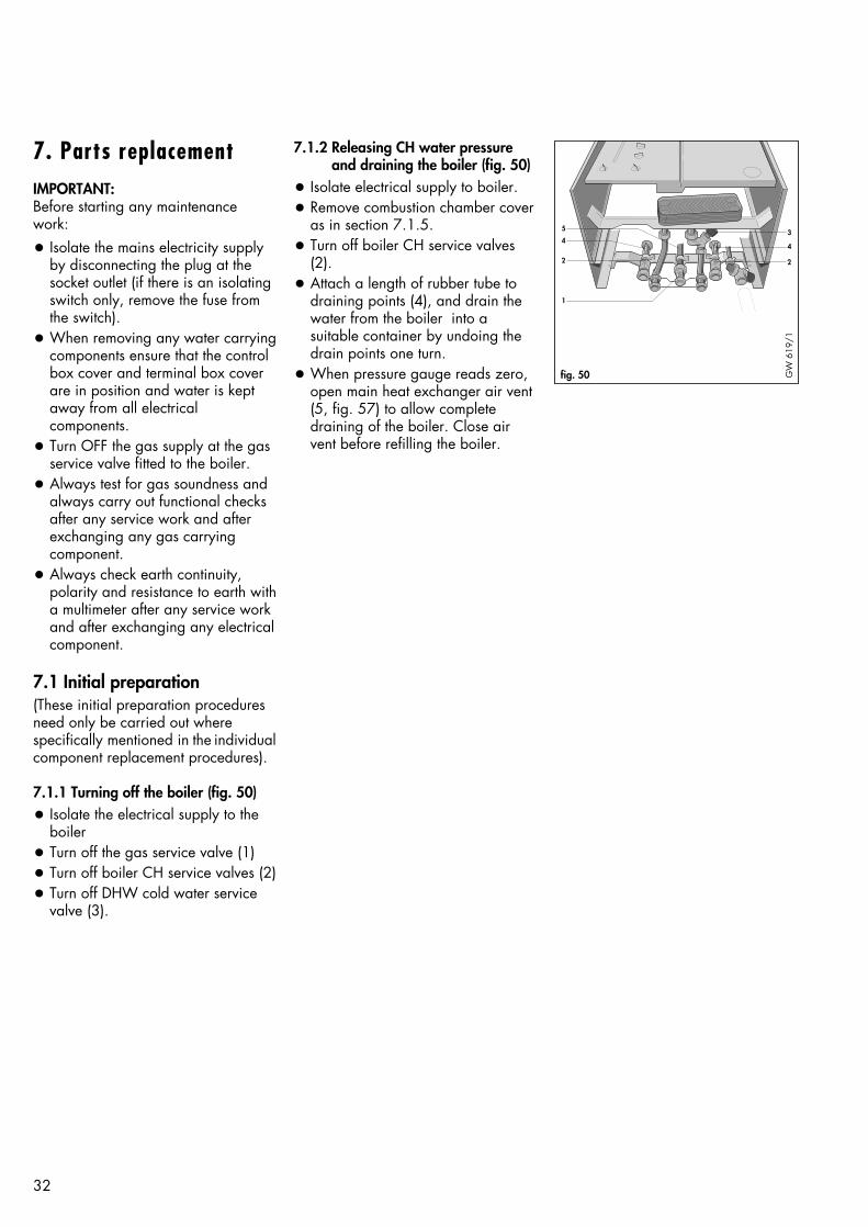
7.1.1 Turning off the boiler (fig. 50)
• Isolate the electrical supply to theboiler
• Turn off the gas service valve (1)• Turn off boiler CH service valves (2)• Turn off DHW cold water service
valve (3).
7.1.2 Releasing CH water pressureand draining the boiler (fig. 50)
• Isolate electrical supply to boiler.• Remove combustion chamber cover
as in section 7.1.5.• Turn off boiler CH service valves
(2).• Attach a length of rubber tube to
draining points (4), and drain thewater from the boiler into asuitable container by undoing thedrain points one turn.
• When pressure gauge reads zero,open main heat exchanger air vent(5, fig. 57) to allow completedraining of the boiler. Close airvent before refilling the boiler.

33
7.1.3 Removal of front casing7.1.3.1 Door (fig. 52)• Remove bottom hinge screw (1)
and pull the bottom door panel forwards and down to release itfrom top hinge pin (2).
7.1.3.2 Top panel (fig. 53)• Slide top panel upwards to release
retaining clips (1).7.1.3.3 Bottom cover plate (fig. 51)• Remove two screws (1) and slacken
two screws (2).• Slide cover forwards and drop
down to remove7.1.3.4 Reassembly• Reassemble in reverse order.
7.1.4 Removal of side casings • Remove front casing as in section
7.1.3.• Remove screws (3, fig. 53) • Remove screws (4, fig. 53) and
retaining brackets.• Slide side case panel upwards to
release retaining clips (2, fig. 53)and lift off.
• Reassemble in reverse order
7.1.5 Removal of combustion chambercover (fig. 54).
• Remove front casing as in section7.1.3,
• Remove four screws (2) securingcombustion chamber front cover
• Lift combustion chamber cover clearof top retaining lugs and pullforward
• Remove combustion chamber coverby first bringing the left sideforward to clear boiler casing.
• Check condition of case seal and ifnecessary replace before refitting
• Reassemble in reverse order,ensuring that the combustionchamber front cover is correctlyfitted and a good seal obtained.
7.1.6 Lower front control panel(fig. 54)
• Remove front casing as in section7.1.3,
• Undo screw (1) and lower controlbox forward from top.
2
1fig. 52 GW
606
/1
4
1
2
3fig. 53 GW
605
/1
1
2
2
fig. 54 GW
613
/1
1 12 2
fig. 51 GW
110
7/1
7.1.7 Removal of heat exchangerfront panel.
• Remove the five screws (1 and 3,fig. 47) securing the heat exchangerand remove the panel by gentlypulling down and forward.

34
7.2 Replacement of fan (fig. 55)• Isolate the boiler from the electrical
supply.
• Remove front casing as in section7.1.3, and remove combustionchamber cover as in section 7.1.5.
• Disconnect the electrical connectionsfrom the fan.
• Remove the 2 fan securing screws(4) and remove fan.
• Reassemble in reverse order.
• Re-fit combustion chamber and frontcasing.
• Carry out electrical checks (seesection 5.1).
7.3 Replacement of air pressureswitch (fig. 56)
• Isolate the boiler from the electricalsupply.
• Remove front casing as in section7.1.3.
• Disconnect electrical connections topressure switch
• Remove screw (1) and lift outpressure switch.
• Disconnect air tubes (2) from switch.
• Reassemble in reverse order.
• Carry out electrical checks (seesection 5.1).
Note: Air tubes should be reconnectedP1 to white tube.P2 to blue tube.(P1 and P2 are marked on airpressure switch).
2 1
fig. 56 GW
640
/1
4
fig. 55 GW
639
/1-a

35
7.4 Replacement of burner• Isolate the boiler from the electrical
supply.
• Remove front casing as in section7.1.3.
• Remove combustion chamber coveras in section 7.1.5
• Disconnect the ignition and flamesensing electrode leads (1, fig. 57).
• Remove two screws (2, fig 57) andpull burner forwards to remove.
• Reassemble in reverse order.
• Carry out electrical checks (seesection 5.1) and check burnerpressure (see section 5.8) and gasrate.
7.5 Replacement of electrodes• Isolate the boiler from the electrical
supply.
• Remove front casing as in section7.1.3, and remove combustionchamber cover as in section 7.1.5
• Remove heat exchanger front panelas in section 7.1.7
• Pull off HT lead (ignition electrode)or sensing wire (flame sensingelectrode) (1, fig 57)
• Depress spring retaining clip (1, fig58) gently pull electrode up andclear of burner.
• To replace the electrode, depressspring retaining clip (1, fig 58) andinsert electrode until the "V" locatesin the cross support (2, fig 58)
• Carry out electrical checks (seesection 5.1).
5423
16
fig. 57
GW
641
/1
2
1
fig. 58 GW
642
/1
36
1
543
2
6fig. 59 G
W 6
43/1
1
1
2
2
fig. 60 Gas
vent
il
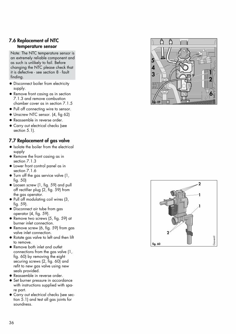
7.6 Replacement of NTCtemperature sensor
Note: The NTC temperature sensor isan extremely reliable component andas such is unlikely to fail. Before changing the NTC please check thatit is defective - see section 8 - faultfinding.
• Disconnect boiler from electricitysupply.
• Remove front casing as in section7.1.3 and remove combustionchamber cover as in section 7.1.5
• Pull off connecting wire to sensor.• Unscrew NTC sensor. (4, fig 62)• Reassemble in reverse order.• Carry out electrical checks (see
section 5.1).
7.7 Replacement of gas valve• Isolate the boiler from the electrical
supply • Remove the front casing as in
section 7.1.3• Lower front control panel as in
section 7.1.6• Turn off the gas service valve (1,
fig. 50)• Loosen screw (1, fig. 59) and pull
off rectifier plug (2, fig. 59) fromthe gas operator.
• Pull off modulating coil wires (3,fig. 59).
• Disconnect air tube from gas operator (4, fig. 59).
• Remove two screws (5, fig. 59) atburner inlet connection.
• Remove screw (6, fig. 59) from gasvalve inlet connection.
• Rotate gas valve to left and then liftto remove.
• Remove both inlet and outletconnections from the gas valve (1,fig. 60) by removing the eight securing screws (2, fig. 60) andrefit to new gas valve using newseals provided.
• Reassemble in reverse order.• Set burner pressure in accordance
with instructions supplied with spa-re part.
• Carry out electrical checks (see sec-tion 5.1) and test all gas joints forsoundness.
37
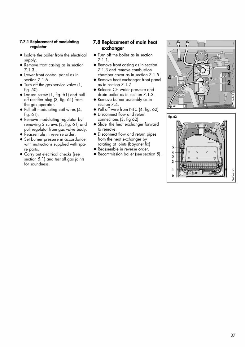
7.7.1 Replacement of modulatingregulator
• Isolate the boiler from the electrical supply.
• Remove front casing as in section7.1.3 .
• Lower front control panel as in section 7.1.6
• Turn off the gas service valve (1, fig. 50).
• Loosen screw (1, fig. 61) and pulloff rectifier plug (2, fig. 61) from the gas operator.
• Pull off modulating coil wires (4,fig. 61).
• Remove modulating regulator byremoving 2 screws (3, fig. 61) andpull regulator from gas valve body.
• Reassemble in reverse order.• Set burner pressure in accordance
with instructions supplied with spa-re parts.
• Carry out electrical checks (see section 5.1).and test all gas jointsfor soundness.
142
3
fig. 61 GW
644
/1
7.8 Replacement of main heatexchanger
• Turn off the boiler as in section7.1.1.
• Remove front casing as in section7.1.3 and remove combustionchamber cover as in section 7.1.5
• Remove heat exchanger front panelas in section 7.1.7
• Release CH water pressure anddrain boiler as in section 7.1.2.
• Remove burner assembly as insection 7.4.
• Pull off wire from NTC (4, fig. 62) • Disconnect flow and return
connections (3, fig 62)• Slide the heat exchanger forward
to remove.• Disconnect flow and return pipes
from the heat exchanger byrotating at joints (bayonet fix)
• Reassemble in reverse order.• Recommission boiler (see section 5).
5423
16
fig. 62
GW
641
/1

38
7.9 Replacement of CHexpansion vessel
In the unlikely event of a failure of theCH expansion vessel follow procedure7.9.1 or 7.9.2 depending upon theinstallation circumstances.
7.9.1. Boiler installed with air/flueduct to left/right hand side, orvertical flue installation (where300mm vertical clearance existsabove the boiler).
• Remove front casing as in section7.1.3
• Turn off the boiler as in section7.1.1.
• Release CH water pressure anddrain boiler as in section 7.1.2.
• Remove combustion chamber coveras in section 7.1.5
• Remove 2 screws (2, fig 63).
• Remove screw (1, fig. 56) torelease air pressure switch.
• Slide expansion vessel upwardsand out of boiler casing.
• Replace in reverse order.
• Refill and repressurise the boiler(see section 5.4).
2 431 12
fig. 64 GW
620
/1
7.9.2 Boiler installed with air flue ductto the rear, or vertical flueinstallation (where less than 300mm vertical clearance existsabove the boiler)
EITHERRemove the boiler from the wall asfollows:
• Remove front casing as in section7.1.3
• Turn off the boiler as in section7.1.1.
• Release CH water pressure anddrain boiler as in section 7.1.2.
• Lower front control panel as insection 7.1.6
• Disconnect external wiring fromboiler wiring terminal box.
• Disconnect flow and returnconnections at compressionconnection above boiler CH servicevalves (1, fig. 64).and remove twoscrews securing retaining lug toappliance chassis(2, fig. 64)
• Disconnect gas connection atcompression joint on top of gasservice valve (3, fig. 64).
• Disconnect domestic hot and coldwater connections (4, fig. 64)
• Disconnect the flue from the top ofboiler as described in section 4.6.
• Remove boiler from wall.
• Remove screw (1, fig. 56) torelease air pressure switch.
• Remove two screws (2, fig. 63) andslide expansion vessel upwardsand out of boiler casing.
• Reassemble in reverse order.
• Re-mount the boiler (see section 4.5and 4.6).
• Re-commission the boiler (seesection 5).
ORA suitable replacement expansionvessel can be fitted externally to theboiler as described in Section 3.7.5(if possible on the central heatingreturn in an accessible position). Inthese circumstances, the replacementexpansion vessel must be correctlysized ignoring the original expansionvessel which can be left in position onthe boiler.
2
1
3
fig. 63 GW
639
/1
39
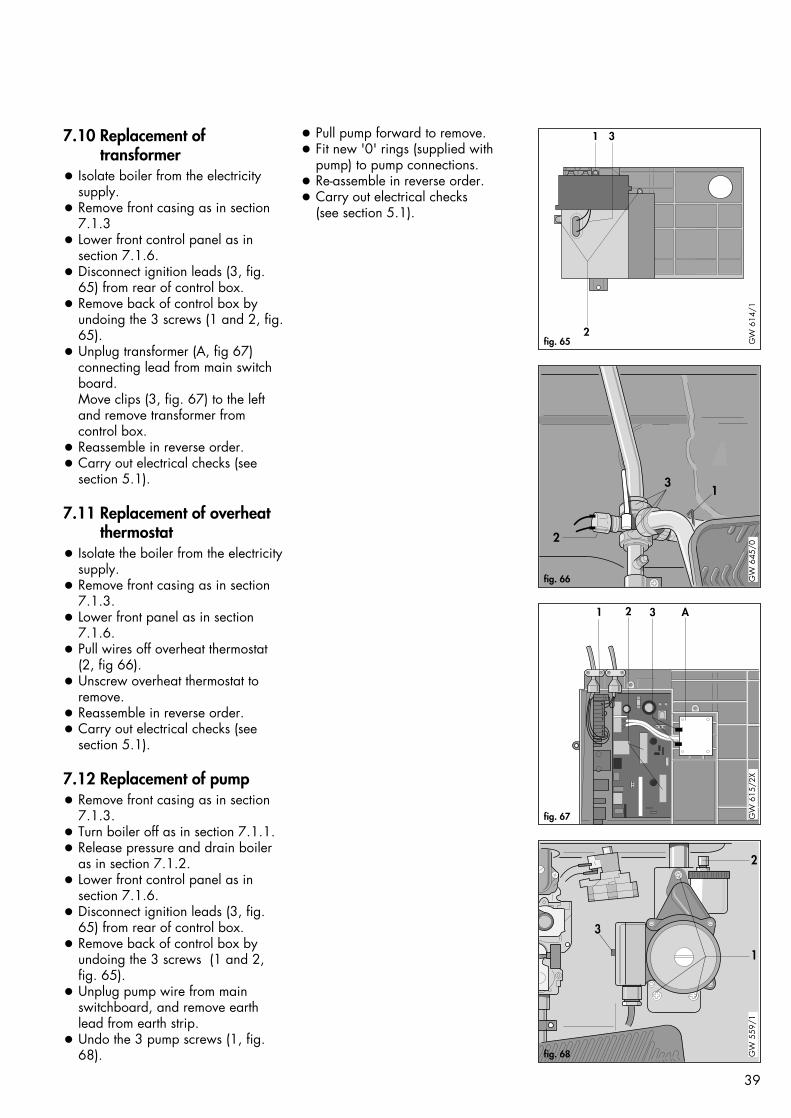
7.10 Replacement of transformer
• Isolate boiler from the electricitysupply.
• Remove front casing as in section7.1.3
• Lower front control panel as insection 7.1.6.
• Disconnect ignition leads (3, fig.65) from rear of control box.
• Remove back of control box byundoing the 3 screws (1 and 2, fig.65).
• Unplug transformer (A, fig 67)connecting lead from main switchboard.Move clips (3, fig. 67) to the leftand remove transformer fromcontrol box.
• Reassemble in reverse order.• Carry out electrical checks (see
section 5.1).
7.11 Replacement of overheat thermostat
• Isolate the boiler from the electricitysupply.
• Remove front casing as in section7.1.3.
• Lower front panel as in section7.1.6.
• Pull wires off overheat thermostat(2, fig 66).
• Unscrew overheat thermostat toremove.
• Reassemble in reverse order.• Carry out electrical checks (see
section 5.1).
7.12 Replacement of pump• Remove front casing as in section
7.1.3.• Turn boiler off as in section 7.1.1.• Release pressure and drain boiler
as in section 7.1.2.• Lower front control panel as in
section 7.1.6.• Disconnect ignition leads (3, fig.
65) from rear of control box. • Remove back of control box by
undoing the 3 screws (1 and 2,fig. 65).
• Unplug pump wire from mainswitchboard, and remove earthlead from earth strip.
• Undo the 3 pump screws (1, fig.68).
1 3
2fig. 65 G
W 6
14/1
2
13
fig. 66 GW
645
/0
NL345
789
1 2 3 A
fig. 67 GW
615
/2X
2
1
3
fig. 68 GW
559
/1
• Pull pump forward to remove.• Fit new '0' rings (supplied with
pump) to pump connections.• Re-assemble in reverse order.• Carry out electrical checks
(see section 5.1).
40
2
1
fig. 69 GW
607
/1
2
1
fig. 70 GW
646
/1
51
6
2345
fig. 71
GW
647
/1
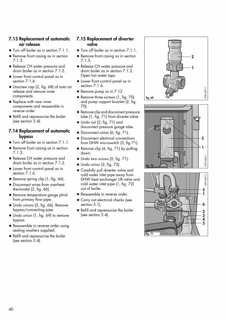
7.13 Replacement of automaticair release
• Turn off boiler as in section 7.1.1.
• Remove front casing as in section7.1.3.
• Release CH water pressure anddrain boiler as in section 7.1.2.
• Lower front control panel as insection 7.1.6.
• Unscrew cap (2, fig. 68) of auto airrelease and remove innercomponents.
• Replace with new innercomponents and reassemble inreverse order.
• Refill and repressurise the boiler(see section 5.4).
7.14 Replacement of automaticbypass
• Turn off boiler as in section 7.1.1.
• Remove front casing as in section7.1.3.
• Release CH water pressure anddrain boiler as in section 7.1.2.
• Lower front control panel as insection 7.1.6.
• Remove spring clip (1, fig. 66).
• Disconnect wires from overheatthermostat (2, fig. 66).
• Remove temperature gauge phialfrom primary flow pipe.
• Undo unions (3, fig. 66). Removebypass/connecting pipe.
• Undo union (1, fig. 69) to removebypass.
• Reassemble in reverse order usingsealing washers supplied.
• Refill and repressurise the boiler(see section 5.4).
7.15 Replacement of divertervalve
• Turn off boiler as in section 7.1.1.
• Remove front casing as in section7.1.3.
• Release CH water pressure anddrain boiler as in section 7.1.2.Open hot water taps.
• Lower front control panel as insection 7.1.6.
• Remove pump as in 7.12
• Remove three screws (1, fig. 70)and pump support bracket (2, fig.70).
• Remove clip and disconnect pressuretube (1, fig. 71) from diverter valve.
• Undo nut (2, fig. 71) and disconnect pressure guage tube.
• Disconnect union (6, fig. 71).
• Disconnect electrical connectionsfrom DHW microswitch (3, fig 71).
• Remove clip (4, fig. 71) by pullingdown.
• Undo two unions (5, fig. 71).
• Undo union (3, fig. 72).
• Carefully pull diverter valve andcold water inlet pipe away fromDHW heat exchanger Lift valve andcold water inlet pipe (1, fig. 72)out of boiler.
• Reassemble in reverse order.
• Carry out electrical checks (seesection 5.1).
• Refill and repressurise the boiler(see section 5.4).

41
7.15.1 Replacement of water sectiondiaphragm (fig. 72).
• Turn off boiler as in Section 7.1.1. • Remove bottom cover as in section
7.1.3.3.• Open hot water taps.• Remove clip (2), undo union (3)• Remove 6 screws (4).• Pull water section base away from
DHW heat exchanger and dropdown.
• Remove diaphragm.• Replace in reverse order.• Carry out electrical checks (see
section 5.1).• Refill and repressurise the boiler
(see section 5.4).
7.16 Replacement of pressureand temperature gauge
• Turn off boiler as in section 7.1.1.• Remove front casing as in section
7.1.3.• Release CH water pressure and
drain boiler as in section 7.1.2.• Lower front control panel as in
section 7.1.6.• Undo union (2, fig 71) on diverter
valve to release pressure gaugetube.
• Remove temperature gauge phialfrom pocket on primary flow pipe.
• Press spring clips on side of gaugeto remove from front panel.
• Replace in reverse order.• Refill and repressurise the boiler
(see section 5.4).
7.17 Replacement of differentialpressure switch
• Turn off boiler as in section 7.1.1.• Remove front casing as in section
7.1.3.• Release CH water pressure and
drain boiler as in section 7.1.2.• Lower front control panel as in
section 7.1.6.• Remove clip at rear of switch by
pulling it to the left.• Disconnect wires from switch (1,
fig. 73).• Pull pressure differential switch
forward to remove.• Reassemble in reverse order.• Carry out electrical checks (see
section 5.1).• Refill and repressurise the boiler
(see section 5.4).
1
2
3
4
5
fig. 72 GW
635
/1-a
1
fig. 73 GW
649
/1

42
1
2
fig. 74 GW
650
/2
7.18 Replacement of DHWmicroswitch.
• Isolate appliance from electricitysupply.
• Remove front casing as in section7.1.3.
• Lower front control panel as insection 7.1.6.
• Lift off microswitch retaining ’bow’spring,
• Pull microswitch forward to removefrom mounting bracket anddisconnect wires.
• Reassemble in reverse order.
• Carry out electrical checks (seesection 5.1).
7.19 Replacement of DHW heatexchanger
• Turn off boiler as in section 7.1.1.
• Remove front casing as in section7.1.3.
• Release CH water pressure anddrain boiler as in section 7.1.2.
• Lower front control panel as insection 7.1.6.
• Unscrew the top two unions (1, fig.74), bottom left hand union andbacknut (2, fig. 74)
Note: The connection between theDHW heat exchanger and watersection is a push fit joint.
• Pull heat exchanger forward toremove.
• Reassemble in reverse order usingnew sealing rings supplied.
• Refill and repressurise the boiler(see Section 5.4).

5 1I II
fig. 76 GW
774
/1
43
7.20 Removal of printed circuitboards (PCBs)
Before commencing work on PCBreplacements carry out the following:-Diagnose that the boards requirechanging using the fault finding guide(see section 8: Fault finding).
• Turn off the boiler as in section7.1.1.
• Remove front casing as in section7.1.3.
• Lower front control panel as insection 7.1.6.
• Remove back of control box byundoing the 3 screws (1 and 2,fig. 65).
• Disconnect ignition leads from rearof control box.
7.20.1 Replacement of switch andcontrol boards
• Disconnect external wiring fromboiler terminal strip.
• Unplug ribbon cable from controlboard (2, fig. 75).
• Unplug all leads from the bothboards (1, fig. 75).
• Pull off switchboard board support.• Pull switchboard carefully out of
control box.• Push four spring retaining clips (5,
fig. 76) out, and gently lift controlboard out of control box.
• Reassemble in reverse order.
Note: When refitting the controlboard, ensure that the user controlspindles (3, fig. 75) are aligned withthe potentiometer and control switchholes (5, fig. 75) and that the locatingrib of the potentiometer/switch correc-tly engages in the groove of the con-trol knob spindle. Also ensure thatwhen refitting the main switchboardthe on/off control knob spindle (3, fig.75) engages correctly into the on/offswitch (5, fig. 75) mounted on theboard.
• Carry out electrical checks (seesection 5.1)
3
5
NL345
789
1 2 A
fig. 75 GW
615
/1

Flame indicator (yellow)Illuminates when flame is recognisedby the flame monitoring system.(A flashing indicator shows that theNTC sensor is broken, not connectedor shorted to earth.)
Burner lockout indicator (red)Illuminates if the burner fails to lightwithin 9 seconds of illumination of theignition indicator after the 2nd igniti-on cycle.(A flashing indicator shows a failurein the electronic boards.)To reset the appliance after a lockout(either burner lockout illuminated orany other indicator light flashing), turnthe central heating control to the resetposition ( ) and release.
44
8. Fault finding
8.1 IntroductionThe TURBOmax has built in diagnosticindicator lights (fig. 77) to assist youwith fault finding in the unlikely eventof a boiler malfunction. The lights willilluminate in sequence, indicating theoperational status of the boiler.Should a fault develop in the boilerthe indicators may flash highlightingthe possible fault e.g.
Power on indicator (green)Illuminates when the electricity supplyto the boiler is on, the main on/offcontrol is set to position ( ) and theinternal boiler fuses are o.k.(A flashing indicator shows that theoverheat thermostat has cut out.)
Hot water demand indicator (yellow)Illuminates whenever there is ademand for hot water i.e. a hot watertap is opened.
Central heating demand indicator (yellow)Illuminates whenever there is ademand for central heating i.e. thecentral heating control is set to position ( ) and the externalheating controls are calling for heat.Note: If the external controls are notcalling for heat (i.e. the room thermostat has reached temperature)this indicator will go out. This is perfectly normal.
Fan operation indicator (yellow)Illuminates to indicate that the fan isoperating and has been checked bythe fan pressure switch.(A flashing indicator shows that the airpressure switch has not made.)
Ignition indicator (yellow)Illuminates when gas valve, operatorand ignition transformer are energised. This indicator remains onduring burner operation.(A flashing indicator shows lack ofwater or poor water circulation in cen-tral heating system.)
0°C
3060
90
120
04
3 2 1bar
8 976
5
43 2 1
8 976
5
43 2 1
fig. 77 GW
849
/1
8.2 Logical fault findingprocedure
8.2.1 Preliminary Checks
These checks must be carried out before attempting to use the fault finding guide:- 1) Carry out electrical safety checks
(see Section 5.1: Preliminary electrical checks).
2) Check that the external electricitysupply to the boiler is on, and a supply of 230 V~ is present between boiler terminals 'L' and'N'.
3) Check that gas supply to the boileris on and that it has been correctlypurged (see Section 5.2: GasSupply).
4) Ensure the heating system is full ofwater and charged to approx. 1 bar. If not refill the system andvent (see section 5.4: Filling theheating system). Ensure boiler flowand return service valves are open.
5) Check that boiler main on/offcontrol is set to position ( )
6) Set boiler central heating control toHeating and Hot Water position( )
7) Ensure that the Maximum RadiatorTemperature and Maximum HotWater Temperature controls are setto position '9'.
8) Check that all the external controlsare on and calling for heat (if noexternal controls are fitted, boilerterminals 3 and 4 must be linked).Check that boiler anti-cycling 'economiser' control is not engaged(see Section 4.8.5).
8.2.2 Procedure
Note: Always check the operation ofthe boiler for central heating first before checking hot water operation.Do not open a hot tap unless instructed to by the fault finding guide.

45
Doe
s gr
een
pow
er `
on`
indi
cato
r (
)
glow
or f
lash
?D
oes
gree
n po
wer
`on
`in
dica
tor (
) fla
sh?
Go
to s
heet
C.
Ensu
re b
oile
r mai
n on
/off
cont
rol i
s se
t to
posi
tion
` `
.
Is 23
0 V
pres
ent a
cros
ste
rmin
als
L an
d N
?Re
set o
verh
eat c
ut-o
ff de
vice
by p
ress
ing
on th
e m
iddl
e of
the
trans
pare
nt ru
bber
cov
er.
Doe
s th
e gr
een
indi
cato
r fla
sh n
ow?
Chec
k el
ectr
ical
sup
ply
and
appl
ianc
e fu
ses
Shee
t A
Che
ck a
nd if
nec
essa
ryre
plac
e 2
A fu
ses
situ
ated
belo
w b
oile
r ter
min
al s
trip
(spa
re fu
se s
uppl
ied
with
appl
ianc
e).
If fu
se is
def
ectiv
e, s
uspe
ctw
iring
faul
t on
exte
rnal
cont
rols
(see
not
e 1)
.
Doe
s gr
een
pow
er `
on`
indi
cato
r glo
w n
ow?
Go
to s
heet
B.
Go
to s
heet
C.
Che
ck c
ontin
uity
of o
verh
eat
ther
mos
tat,
repl
ace
ifne
cess
ary.
Doe
s th
e gr
een
indi
cato
r fla
sh n
ow?
Che
ck tr
ansf
orm
er (A
, fig
. 67)
230
V A
C p
rimar
y (b
lack
/re
d) a
nd a
ppro
x. 1
7 V
seco
ndar
y (b
lue/
brow
n)D
oes
the
indi
cato
r fla
sh n
ow?
Repl
ace
elec
troni
c bo
ards
.
Repa
ir ex
tern
alw
iring
faul
t.
Yes
No
No
No
No
Yes
Yes
Yes
Yes
Yes
Yes
No
No
Not
e 1
For t
est p
urpo
ses,
dis
conn
ect
exte
rnal
con
trols
from
term
inal
s3
- 4 a
nd re
plac
e w
ith a
brid
gebe
twee
n th
ese
term
inal
s. If
appl
ianc
e th
en o
pera
tes,
the
faul
t is
with
the
exte
rnal
con
trols.
No

46
Is 23
0 V
pres
ent a
cros
sbo
iler t
erm
inal
s 3
and
5?D
oes
gree
n po
wer
`on
`in
dica
tor (
) gl
ow n
ow?
Go
to s
heet
C.
Boile
r on/
off c
ontro
l def
ectiv
e,re
plac
e el
ectro
nic
boar
ds.
Che
ck, r
epla
ce 1
.25
A fu
sene
xt to
the
trans
form
er p
lug
(spa
re fu
se p
rovi
ded
with
the
appl
ianc
e). D
oes
gree
n in
dica
tor g
low
now
?
Chec
k m
ain
on/o
ff co
ntro
l, ov
erhe
at th
erm
osta
t and
ant
i-sur
ge fu
seSh
eet B
Che
ck tr
ansf
orm
er (A
, fig
. 67)
230
V A
C p
rimar
y (b
lack
/re
d) a
nd a
ppro
x. 1
7 V
seco
ndar
y (b
lue/
brow
n)D
oes
the
indi
cato
r glo
w n
ow?
Repl
ace
elec
troni
c bo
ards
.
Yes
Yes
Yes
No
No
No
No
Yes

47
Doe
s ye
llow
cen
tral h
eatin
gde
man
d in
dica
tor (
)
glo
w?
Doe
s bu
rner
ligh
t?G
o to
she
et H
.C
heck
cen
tral h
eatin
g co
ntro
lsw
itch
is s
et to
the
posi
tion
(
).
Chec
k Ce
ntra
l Hea
ting
cont
rol a
nd e
xter
nal c
ontr
ols
Shee
t C
If th
e ce
ntra
l hea
ting
dem
and
indi
cato
r (
) s
till d
oes
not
glow
, rep
lace
ele
ctro
nic
boar
ds.
Yes
Yes
No
No
Go
to s
heet
D.
Is 23
0 V
AC
pre
sent
acr
oss
boile
r ter
min
als
4 an
d 5?
Exte
rnal
faul
t. C
heck
whe
ther
all e
xter
nal c
ontro
ls ar
eca
lling
for h
eat,
repl
ace
orre
pair
as n
eces
sary
(see
also
note
1, s
heet
A).N
o
Yes
No

48
Doe
s pu
mp
run?
Doe
s th
e ye
llow
igni
tion
indi
cato
r ( )
flas
h af
ter 3
0s?
Has
sys
tem
bee
nfil
led
with
wat
er?
Doe
s bu
rner
ligh
t?
Chec
k op
erat
ion
of p
ump
Shee
t D
Doe
s th
e ye
llow
igni
tion
indi
cato
r ( )
flas
h af
ter 3
0s?
Turn
boi
ler o
n/of
f con
trol
switc
h of
f, th
en o
n ag
ain.
Che
ck m
axim
um ra
diat
orte
mpe
ratu
re c
ontro
l is
set h
igh
enou
gh (e
. g. 9
). D
oes
the
pum
p ru
n no
w?
Is 23
0 V
pres
ent a
t the
pum
ppl
ug c
onne
ctio
n (X
10) o
n th
eel
ectro
nic
boar
ds?
Repl
ace
elec
troni
c bo
ards
.
Che
ck p
ump,
repl
ace
asne
cess
ary.
Yes
Yes
No
No
Yes
No
No
No
No
Yes
Go
to s
heet
H.
Go
to s
heet
E.
Fill
and
vent
syste
m.
No
Go
to s
heet
F.
Yes
Yes
Yes

49
Doe
s fa
n ru
n?D
oes
yello
w fa
n op
erat
ion
indi
cato
r (
) f
lash
?D
oes
yello
w fl
ame
indi
cato
r (
) fla
sh?
Doe
s ye
llow
fan
oper
atio
nin
dica
tor f
lash
or g
low
?
Che
ck a
ir/flu
e ga
s sy
stem
isco
rrec
tly fi
tted
and
not
obstr
ucte
d. C
heck
pito
t tub
e(in
fan
outle
t) an
d ai
r hos
esar
e no
t obs
truct
ed a
nd a
reco
rrec
tly a
ligne
d. C
heck
or
repl
ace
air p
ress
ure
switc
h.
Chec
k fa
n/flu
e ga
s sy
stem
Shee
t E
Is 23
0 V
pres
ent a
cros
sfa
n te
rmin
als?
Doe
s ye
llow
cen
tral h
eatin
gde
man
d in
dica
tor (
)
glow
?
No
heat
dem
and.
Go
to s
heet
C.
Che
ck/r
epla
ce fa
n.
Yes
No
Yes
Yes
No
No
No
No
Yes
Switc
h m
ain
on/o
ff co
ntro
l off
and
on a
gain
.Ye
s
Che
ck N
TC. D
isco
nnec
t NTC
lead
at p
lug
(3, f
ig. 3
7).
Doe
s fa
n ru
n no
w?
Che
ck c
onne
ctio
n to
NTC
tem
pera
ture
sen
sor,
clea
n an
dtig
hten
. Che
ck N
TC n
ot
shor
tene
d to
ear
th. I
f O.K
re
plac
e N
TC s
enso
r.
Repl
ace
elec
troni
c bo
ards
.
No
Yes
Doe
s ye
llow
flam
ein
dica
tor (
) g
low
?
Def
ectiv
e el
ectro
nic
boar
ds.
No
Doe
s bu
rner
ligh
t?Ye
s
Go
to s
heet
F.
No
Go
to s
heet
H.
Yes
Yes
Doe
s ye
llow
flam
ein
dica
tor (
) f
lash
?
No
Che
ck p
itot t
ube
(in fa
n ou
tlet)
and
air h
oses
are
not
ob
struc
ted
and
corr
ectly
alig
ned.
Che
ck o
r rep
lace
air
pres
sure
sw
itch.Ye
s
Doe
s fa
n ru
n no
w?
No
YesN
o

50
Doe
s sp
arki
ng s
tart?
Go
to s
heet
.H
Doe
s ye
llow
igni
tion
indi
cato
r(
) fla
sh a
fter 3
0s?
Repl
ace
elec
troni
c bo
ards
.
Chec
k op
erat
ion
of d
iffer
entia
l pre
ssur
e sw
itch
Shee
t F
Has
sys
tem
bee
n fil
led
with
wat
er?
Is so
leno
id a
ctiv
ated
?
Is di
ffere
ntia
l pre
ssur
e sw
itch
activ
ated
?
Che
ck fo
r dirt
or d
amag
e to
the
diffe
rent
ial s
witc
h, s
uppl
ytu
bes
and
diap
hrag
m.
Go
to s
heet
G.
Yes
Yes
No
Yes
No
No
No
Yes
Fill
and
vent
sys
tem
and
boile
r.N
o
Che
ck c
ontin
uity
of
mic
rosw
itch.
Rep
lace
if
nece
ssar
y. C
heck
con
nect
ion
of ri
bbon
plu
g to
sw
itch
boar
d.If
burn
er s
till f
ails
to li
ght,
repl
ace
elec
troni
c bo
ards
.
Yes
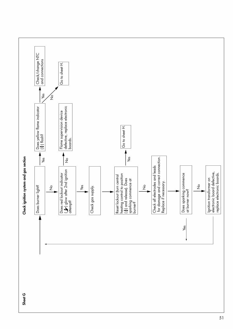
51
Doe
s bu
rner
ligh
t?D
oes
yello
w fl
ame
indi
cato
r(
) fla
sh?
Che
ck/c
hang
e N
TCan
d co
nnec
tions
Doe
s re
d lo
ckou
t ind
icat
or(
) g
low
afte
r 2nd
igni
tion
atte
mpt
?
Chec
k ig
nitio
n sy
stem
and
gas
sec
tion
Shee
t G
Yes
Yes
No
Flam
e su
perv
isio
n de
vice
defe
ctiv
e, re
plac
e el
ectro
nic
boar
ds.
Che
ck g
as s
uppl
y.
Rese
t loc
kout
(tur
n ce
ntra
lhe
atin
g co
ntro
l to
posi
tion
( )
and
rele
ase)
. Doe
s sp
arki
ng c
omm
ence
at
burn
er?
Go
to s
heet
H.
No
Yes
No Yes
Go
to s
heet
H.
Che
ck a
ll el
ectro
des
and
lead
s fo
r dam
age
and
corr
ect c
onne
ctio
n.Re
plac
e if
nece
ssar
y.
No
Doe
s sp
arki
ng c
omm
ence
at
bur
ner n
ow?
Igni
tion
trans
form
er o
nel
ectro
nic
boar
d de
fect
ive,
re
plac
e el
ectro
nic
boar
ds.
No
Yes

52
Doe
s ye
llow
flam
e in
dica
tor
( )
glow
and
flam
es in
crea
sein
siz
e to
full
rate
?
Doe
s bu
rner
flam
e m
odul
ate/
go o
ut w
hen
max
imum
radi
ator
tem
pera
ture
con
trol
is tu
rned
dow
n to
pos
ition
1at
a fl
ow te
mpe
ratu
re o
fap
prox
. 50
degr
ee C
?
Che
ck p
oten
tiom
eter
for
parti
al lo
ad s
ettin
g (s
ee 5
.9C
.H. r
ange
ratin
g).
Pull
of c
able
from
NTC
and
sh
ort-c
ircui
t to
earth
. Is
flam
eex
tingu
ishe
d?
Chec
k op
erat
ion
of b
urne
r an
d m
odul
atio
nSh
eet H
Che
ck p
lug-
in c
onne
ctio
nsto
mod
ulat
ing
sole
noid
.
Repl
ace
mod
ulat
ing
regu
lato
r of
gas
val
ve if
bur
ner s
till f
ails
to in
crea
se to
full
rate
.
Yes
No
No
No
Repl
ace
elec
troni
c bo
ards
.
Go
to s
heet
J.
Yes
Is fla
me
extin
guis
hed
afte
r 2n
d ig
nitio
n at
tem
pt, a
nd re
dlo
ckou
t ind
icat
or (
)
lit?
Is fla
me
visi
ble
prio
r to
lock
out c
ondi
tion?
Che
ck g
as s
uppl
y is
live
and
pu
rged
.
Che
ck c
onne
ctio
ns/o
pera
tion
of b
oth
sole
noid
s, re
plac
e ga
sva
lve
as n
eces
sary
.
Yes
No
No
Che
ck/c
lean
bur
ner,
ioni
zatio
n se
nsor
and
cab
lefo
r def
ects,
goo
d co
ntac
tsan
d co
rrec
t pos
ition
.
Che
ck a
ir/flu
e ga
s sy
stem
isco
rrec
tly fi
tted
and
not
obstr
ucte
d. If
lock
out o
ccur
sre
plac
e el
ectro
nic
boar
ds.
Yes
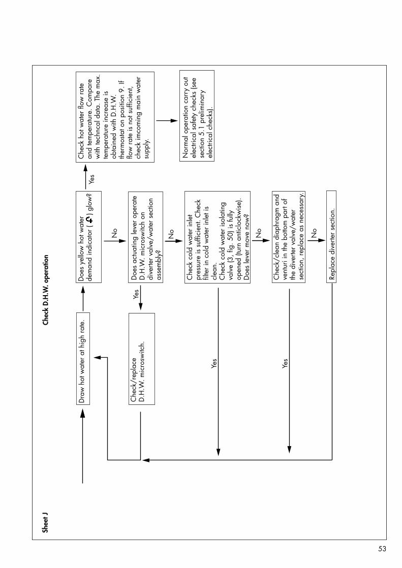
53
Doe
s ye
llow
hot
wat
erde
man
d in
dica
tor (
)
glo
w?
Che
ck h
ot w
ater
flow
rate
and
tem
pera
ture
. Com
pare
with
tech
ncal
dat
a. T
he m
ax.
tem
pera
ture
incr
ease
isob
tain
ed w
ith D
.H.W
. th
erm
osta
t on
posi
tion
9. If
flow
rate
is n
ot s
uffic
ient
, ch
eck
imco
min
g m
ain
wat
ersu
pply.
Nor
mal
ope
ratio
n ca
rry
out
elec
trica
l saf
ety
chec
ks (s
eese
ctio
n 5.
1 pr
elim
inar
yel
ectri
cal c
heck
s).
Chec
k D
.H.W
. ope
ratio
nSh
eet J
Doe
s ac
tuat
ing
leve
r ope
rate
D.H
.W. m
icro
switc
h on
di
verte
r val
ve/w
ater
sec
tion
asse
mbl
y?
Che
ck c
old
wat
er in
let
pres
sure
is s
uffic
ient
. Che
ckfil
ter i
n co
ld w
ater
inle
t is
clea
n.C
heck
col
d w
ater
isol
atin
gva
lve
(3, f
ig. 5
0) is
fully
open
ed (t
urn
antic
lock
wis
e).
Doe
s le
ver m
ove
now
?
Yes
No
Dra
w h
ot w
ater
at h
igh
rate
.
Che
ck/r
epla
ce
D.H
.W. m
icro
switc
h.
Che
ck/c
lean
dia
phra
gm a
ndve
ntur
i in
the
botto
m p
art o
fth
e di
verte
r val
ve/w
ater
sect
ion,
repl
ace
as n
eces
sary
.
Repl
ace
dive
rter s
ectio
n.
No
No
No
Yes
Yes
Yes

54
9 Electrical diagrams9.1 Functional Flow diagram: VUW 242/1 E, 282/1 E
GW
651
/1
MAIN SWITCH
CONTROL BOX
MAIN SWITCHBOARD MAINTRANSFORMER230V
20V
POWER SUPPLY
CONTROL BOARD
WATER-PUMPSELECTOR
OVERHEATTHERMOSTAT
FAN-CONTROL
AIRPRESSURESWITCH
FAN
PUMP
DHWMICROSWITCH
FLAMESENSOR
GASVALVE
GAS BURNER CONTROLLEGEND
NOTEALL UNCODEDWIRES ARE BLACK
b bluebr brownr redt transparent t
r
r
NTCTEMPERATURESENSOR
PRESSSUREDIFFERENTIALSWITCH
IGNITION ELECTRODES
b
br
IGNITIONTRANSFORMER
L2 1
F2A F2A N
plug in connector
plug in connector
fig. 78

55
9.2 Wiring diagram: VUW 242/1 E, 282/1 E
fig. 79 GW 1542/0
Com
bust
ion
cham
ber
Cont
rol b
ox
Flam
e se
nsin
gel
ectro
deIg
nitio
nel
ectro
deN
TC s
enso
rFa
nW
ater
switc
hPr
essu
re d
iffer
entia
lsw
itch
Ove
rhea
t th
erm
osta
tA
ir pr
essu
resw
itch
Gas
val
vePu
mp
Mai
ntra
nsfo
rmer
Igni
tion
trans
form
erM
ain
switc
hboa
rd
Con
trol
boar
d

56
9.3 Schematic appliance circuit diagram: VUW 242/1 E, 282/1 E
GW
652
/1
FAN
b
br
t
r r
FLAME-SENSORIGNITION-ELECTRODES
GAS VALVEPUMPPRESSURE
DIFFERENTIALSWITCH
OVERHEATTHERMOSTAT
MAIN SWITCHBOARD
CONTROL-BOARD
CONTROL-BOX
DHW MICROSWITCH
9
IGNITIONTRANSFORMER
greyorangegreen
8 MAINTRANSFORMER
7 5 4 3 LN
NTCTEMPERATURESENSOR
AIR PRESSURE SWITCH
LEGENDb bluebr brownr redt transparent
fig. 80

57
10. Short parts list Key No. Description Part No. GC No.
01 Fan 19 016202 Air pressure switch 05 055703 Main heat exchanger VUW 242/1 06 495104 Main heat exchanger VUW 282/1 06 495205 Burner VUW 242/1 04 196006 Burner VUW 282/1 04 196107 Diverter valve 01 126908 DHW heat exchanger 06 495009 Ignition electrode 09 056210 Flame sensing electrode 09 056311 HT lead (ignition electrode) 09 153412 Expansion vessel 18 104513 Pump 16 111114 Gas valve (natural gas) 05 336915 Modulating regulator (natural gas) 17 037616 DHW microswitch 12 625517 Diaphragm 01 035718 Switch and control board 13 043819 Main transformer 28 744220 NTC temperature sensor 25 280521 Temperature and pressure gauge 10 1558
01
fig. 81 GW
688
/1
03/04
fig. 83 GW
695
/1
02
fig. 82 GW
680
/1
05/06
fig. 84 GW
696
/2
07
fig. 85 GW
694
/1
08
fig. 86 GW
687
/1

58
10
fig. 88 GW
684
/1
13
fig. 90 GW
686
/1
15
fig. 92 GW
682
/1
09
fig. 87 GW
683
/1
12
fig. 89 GW
693
/1
14fig. 91 G
W 6
91/1
16
fig. 93 GW
689
/1
17
fig. 94 GW
690
/1
NL345
789
18
19
fig. 95 GW
692
/1
20
fig. 96 GW
685
/2
21
fig. 97 GW
681
/2
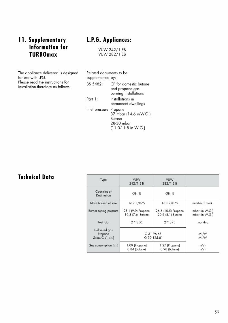
Type VUW VUW242/1 E B 282/1 E B
Countries of GB, IE GB, IEDestination
Main burner jet size 16 x 7/075 18 x 7/075 number x mark.
Burner setting pressure 25.1 (9.9) Propane 26.6 (10.5) Propane mbar (in W.G.)19.3 (7.6) Butane 20.6 (8.1) Butane mbar (in W.G.)
Restrictor 2 * 350 2 * 375 marking
Delivered gasPropane G 31 96.65 MJ/m3
Gross C.V. (s.t.) G 30 125.81 MJ/m3
Gas consumption (s.t.) 1.09 (Propane) 1.27 (Propane) m3/h0.84 (Butane) 0.98 (Butane) m3/h
59
Technical Data
L.P.G. Appliances:VUW 242/1 EBVUW 282/1 EB
The appliance delivered is designedfor use with LPG.Please read the instructions forinstallation therefore as follows:
Related documents to be supplemented by:
BS 5482: CP for domestic butaneand propane gas burning installations
Part 1: Installations in permanent dwellings
Inlet pressure: Propane37 mbar (14.6 inW.G.)Butane28-30 mbar (11.0-11.8 in W.G.)
11. Supplementary information forTURBOmax

8330
50
GB/
IE
HEATING, CONTROLS, HOT WATER
0698
VPr
inte
d in
Ger
man
y - I
mpr
imé
en A
llem
agne
Prin
ted
on 1
00 %
recy
cled
pap
erSu
bjec
t to
alte
ratio
nW
e do
not
acc
ept l
iabi
lity
for d
amag
e ar
isin
g as
a re
sult
of th
e no
n-ob
serv
ance
of t
hese
instr
uctio
ns
Head OfficeVaillant Ltd., Vaillant House,Medway City Estate, Trident Close,Rochester, Kent ME2 4EZ
Sales 01634 292310Service Solutions 0870 6060 777Technical Advice 01634 292392Training 01634 292370