instructions for m.o.r.e.™ 9930 steering correction …
TRANSCRIPT
MOUNTAIN OFF ROAD ENTERPRISES LLC. P.O. BOX 690, DELTA, COLORADO, 81416 970-625-0500 970-625-3747 Fax
EMAIL: [email protected]
www.mountainoffroad.com
INSTRUCTIONS FOR M.O.R.E.™ 9930 STEERING CORRECTION KIT PLEASE READ TERMS AND POLICIES ON PAGE 3 OF THESE INSTRUCTIONS
PAGE 1 of 5
CONTENTS OF KIT 9930: Tie Rod-Long, Drag Link-Short Heim Joints & Jam Nuts 5/8“ (Left & Right threads) Bracket-passenger side knuckle # (9923) Hardware # (9925) Please note: Some of the photos in these instructions are of proto-type parts and the parts that you have may differ in appearance.
General Information: This Steering Correction Kit is designed to fit Jeep® YJ Wrangler vehicles built from
1987-1995 that have had the leaf springs installed on top of the axle housings, known as a spring over axle (S.O.A.) conversion. The stock YJ Dana model 30 front axle must be utilized. Most S.O.A. conversions are performed on a custom basis, which means that there is not a standard “kit” available. This makes it difficult for M.O.R.E.™ to be certain that this steering correction kit will fit perfectly on every vehicle. We have spent countless hours designing and test fitting this system to several different vehicles and have found that it works well with most all, however, we cannot guarantee that it will install perfectly on your Jeep®. It may require a bit of “customizing” on your part to be installed properly. Since you have purchased this part number and not the kit that contains the dropped pitman arm, M.O.R.E.™ assumes that you already have one installed. It is mandatory for proper fit of this system. If you do not have the dropped pitman arm, do not attempt to install this kit, because it will not work with out one! M.O.R.E.™ highly recommends the use of a trac bar with S.O.A. conversions. If you need one, M.O.R.E.™ offers two different styles that are far better then the stock unit. The SlipLoc™ or DoubleJointed™ trac bar, along with our special riser bracket (# 9921) will work great with your S.O.A. conversion. Read through all of the instructions before you begin installation, and familiarize yourself with all steps and components in the kit.
Features: This M.O.R.E.™ Steering Correction Kit replaces the stock tie rod and drag link with new units. The
main design feature is it moves the drag link to above the leaf spring and keeps it as parallel to the tie rod as possi-
ble. Also the tie rod moves to on top of the knuckle arms for increased ground clearance*. This kit is designed to be
a bolt on, with only minor drilling required, no welding. You will have to do some minor grinding and tapping of holes.
*In some cases, a 1/2” thick spacer (lift block) must be installed under the spring stack in order to gain clearance for
the tie rod. This is included in this kit along with a new spring center bolt. Please call if you have any questions.
Tools Required: In addition to basic hand tools, the following tools which may not be in every work shop will be
needed: Drill press or milling machine (hand power drill can be used) with 1/2” chuck, drill bits in the following sizes: 5/8 (.625), 27/64 (.422), 21/64 (.328). End tap 3/8–24 thread (fine), box end wrench (15/16”), open end wrench (1-1/8“), socket (15/16”) -1/2” drive, torque wrench - 1/2” drive, 13MM-12 point (metric) socket, pitman arm puller, two 1/2” x 3-1/2” bolts and nuts, hand grinder.
STEP 1: With the Jeep® on flat level ground (concrete), jack up the front axle and place it on jack stands.
Remove the front tires/wheels. Remove the stock steering linkage (tie rod and drag link).
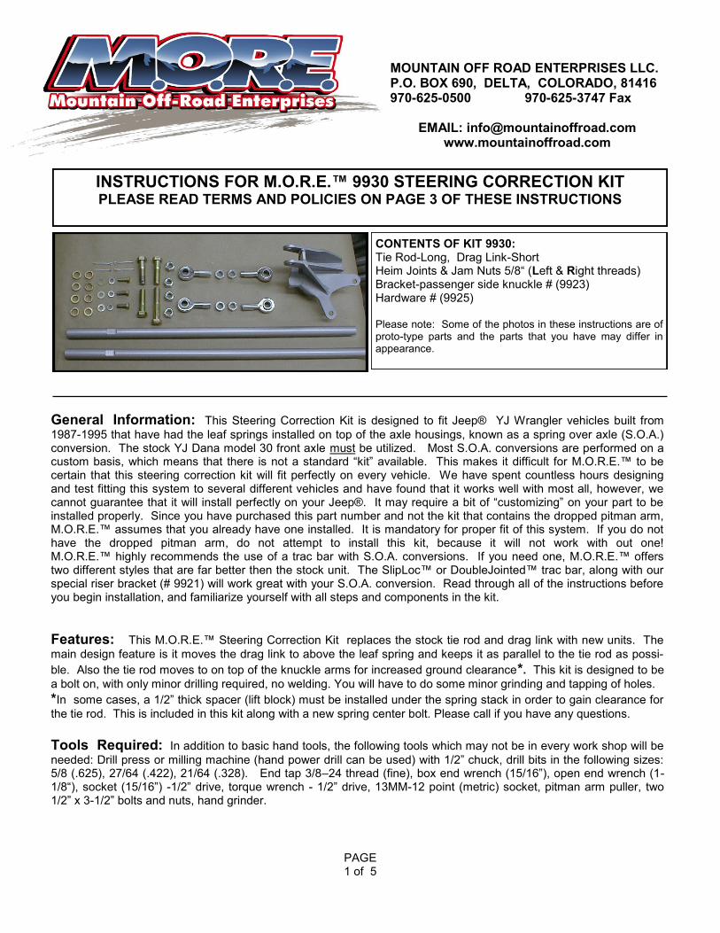
STEP 2: The pitman arm has a tapered hole that the drag link attached to. This hole must be drilled to
5/8”. M.O.R.E.™ has found it best to remove it from the steering box (this requires a pitman arm puller). Place it in a drill press or milling machine for this step. See figure 1. This can be done with a hand power drill with the pitman arm on the vehicle, if you can drill the hole very accurately. You be the judge.
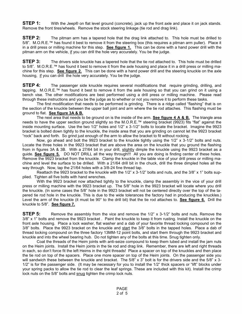
STEP 3: The drivers side knuckle has a tapered hole that the tie rod attached to. This hole must be drilled
to 5/8”. M.O.R.E.™ has found it best to remove it from the axle housing and place it in a drill press or milling ma-chine for this step. See figure 2. This can be done with a hand power drill and the steering knuckle on the axle housing, if you can drill the hole very accurately. You be the judge.
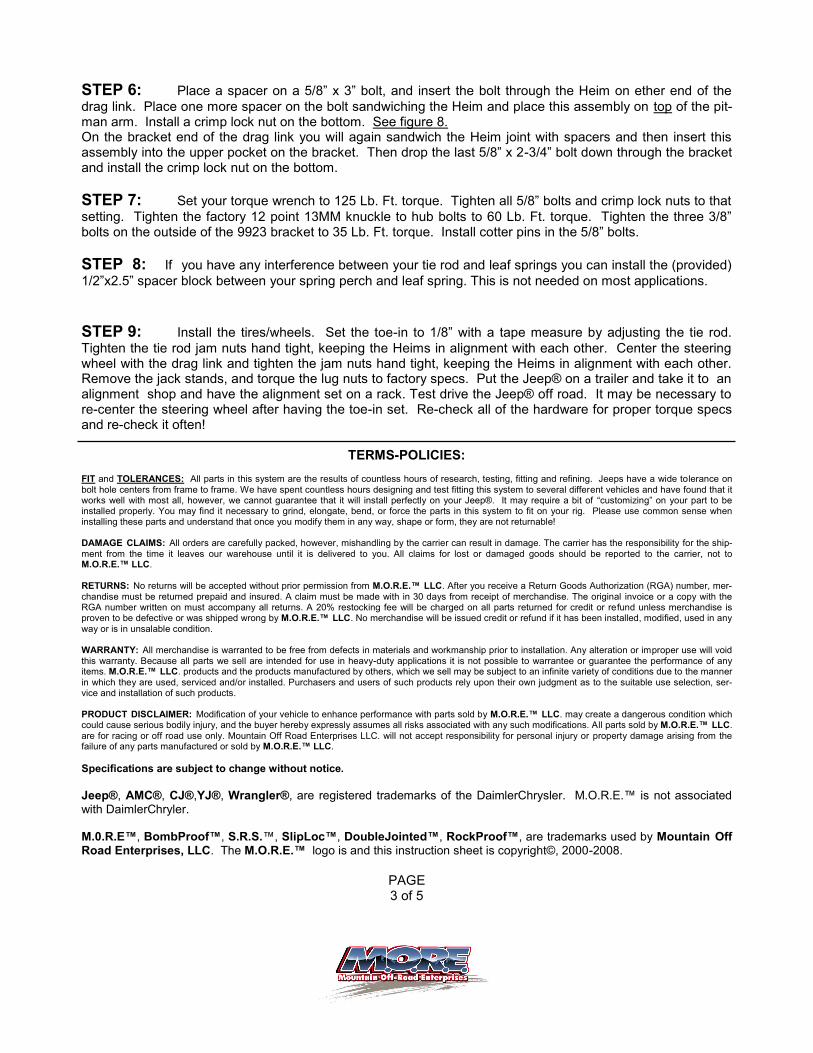
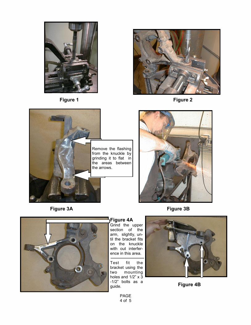
STEP 4: The passenger side knuckle requires several modifications that require grinding, drilling, and
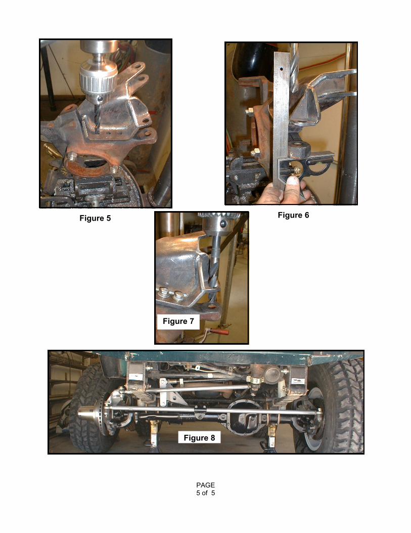
tapping. M.O.R.E.™ has found it best to remove it from the axle housing so that you can grind on it using a bench vise. The other modifications are best performed using a drill press or milling machine. Please read through these instructions and you be the judge as to whether or not you remove it to perform these tasks. The first modification that needs to be performed is grinding. There is a ridge called “flashing” that is on the section of the knuckle between the upper ball joint and arm where the tie rod attaches. This flashing must be ground to flat. See figure 3A & B. The next area that needs to be ground on is the inside of the arm. See figure 4 A & B. The triangle area needs to have the upper section ground slightly so the M.O.R.E.™ steering bracket (9923) fits “flat” against the inside mounting surface. Use the two 1/2” holes and 1/2” x 3-1/2” bolts to locate the bracket. Imagine the 9923 bracket is bolted down tightly to the knuckle, the inside area that you are grinding on cannot let the 9923 bracket “rock” back and forth. So grind just enough of the arm to allow the bracket to fit without rocking. Now, go ahead and bolt the 9923 bracket to the knuckle tightly using the 1/2” x 3-1/2” bolts and nuts. Locate the three holes in the 9923 bracket that are above the area on the knuckle that you ground the flashing from in figures 3A & 3B. With a 27/64 bit in your drill, slightly dimple the knuckle using the 9923 bracket as a guide. See figure 5. DO NOT DRILL all the way through!!! All you are doing is finding center of these holes. Remove the 9923 bracket from the knuckle. Clamp the knuckle in the table vice of your drill press or milling ma-chine and level the surface to be drilled. With a 21/64 drill bit in the chuck, drill the three dimpled holes all the way through. Now, tap the 21/64 holes with a 3/8-24 fine thread tap. Reattach the 9923 bracket to the knuckle with the 1/2” x 3-1/2” bolts and nuts, and the 3/8” x 1” bolts sup-plied. Tighten all five bolts with hand wrenches. With the 9923 bracket now attached tightly to the knuckle, clamp the assembly in the vice of your drill press or milling machine with the 9923 bracket up. The 5/8” hole in the 9923 bracket will locate where you drill the knuckle. (In some cases the 5/8” hole in the 9923 bracket will not be centered directly over the top of the ta-pered tie rod hole in the knuckle. This is due to the wide tolerances the factory had in producing the knuckles.) Level the arm of the knuckle (it must be 90° to the drill bit) that the tie rod attaches to. See figure 6. Drill the knuckle to 5/8”. See figure 7.
STEP 5: Remove the assembly from the vice and remove the 1/2” x 3-1/2” bolts and nuts. Remove the
3/8” x 1” bolts and remove the 9923 bracket . Paint the knuckle to keep it from rusting. Install the knuckle on the front axle housing. Place a lock washer, flat washer and a dab of your favorite thread locking compound on the 3/8” bolts. Place the 9923 bracket on the knuckle and start the 3/8” bolts in the tapped holes. Place a dab of thread locking compound on the three factory 13MM-12 point bolts, and start them through the 9923 bracket and knuckle and into the wheel bearing hub. Do not tighten any of the bolts at this time. Snug tighten only. Coat the threads of the Heim joints with anti-seize compound to keep them lubed and install the jam nuts on the Heim joints. Install the Heim joints in the tie rod and drag link. Remember, there are left and right threads in each, so don’t force fit the left Heims in the right threads! Place a spacer on top of the knuckles and then place the tie rod on top of the spacers. Place one more spacer on top of the Heim joints. On the passenger side you will sandwich these between the knuckle and bracket. The 5/8” x 3” bolt is for the drivers side and the 5/8” x 3-1/2” is for the passenger side. (It may be necessary for you to install the 1/2” thick spacers or “lift” blocks under your spring packs to allow the tie rod to clear the leaf springs. These are included with this kit). Install the crimp lock nuts on the 5/8” bolts and snug tighten the crimp lock nuts.
PAGE 2 of 5
STEP 6: Place a spacer on a 5/8” x 3” bolt, and insert the bolt through the Heim on ether end of the
drag link. Place one more spacer on the bolt sandwiching the Heim and place this assembly on top of the pit-man arm. Install a crimp lock nut on the bottom. See figure 8. On the bracket end of the drag link you will again sandwich the Heim joint with spacers and then insert this assembly into the upper pocket on the bracket. Then drop the last 5/8” x 2-3/4” bolt down through the bracket and install the crimp lock nut on the bottom.
STEP 7: Set your torque wrench to 125 Lb. Ft. torque. Tighten all 5/8” bolts and crimp lock nuts to that
setting. Tighten the factory 12 point 13MM knuckle to hub bolts to 60 Lb. Ft. torque. Tighten the three 3/8” bolts on the outside of the 9923 bracket to 35 Lb. Ft. torque. Install cotter pins in the 5/8” bolts.
STEP 8: If you have any interference between your tie rod and leaf springs you can install the (provided)
1/2”x2.5” spacer block between your spring perch and leaf spring. This is not needed on most applications.
STEP 9: Install the tires/wheels. Set the toe-in to 1/8” with a tape measure by adjusting the tie rod.
Tighten the tie rod jam nuts hand tight, keeping the Heims in alignment with each other. Center the steering wheel with the drag link and tighten the jam nuts hand tight, keeping the Heims in alignment with each other. Remove the jack stands, and torque the lug nuts to factory specs. Put the Jeep® on a trailer and take it to an alignment shop and have the alignment set on a rack. Test drive the Jeep® off road. It may be necessary to re-center the steering wheel after having the toe-in set. Re-check all of the hardware for proper torque specs and re-check it often!
TERMS-POLICIES: FIT and TOLERANCES: All parts in this system are the results of countless hours of research, testing, fitting and refining. Jeeps have a wide tolerance on bolt hole centers from frame to frame. We have spent countless hours designing and test fitting this system to several different vehicles and have found that it works well with most all, however, we cannot guarantee that it will install perfectly on your Jeep®. It may require a bit of “customizing” on your part to be installed properly. You may find it necessary to grind, elongate, bend, or force the parts in this system to fit on your rig. Please use common sense when installing these parts and understand that once you modify them in any way, shape or form, they are not returnable! DAMAGE CLAIMS: All orders are carefully packed, however, mishandling by the carrier can result in damage. The carrier has the responsibility for the ship-
ment from the time it leaves our warehouse until it is delivered to you. All claims for lost or damaged goods should be reported to the carrier, not to M.O.R.E.™ LLC. RETURNS: No returns will be accepted without prior permission from M.O.R.E.™ LLC. After you receive a Return Goods Authorization (RGA) number, mer-chandise must be returned prepaid and insured. A claim must be made with in 30 days from receipt of merchandise. The original invoice or a copy with the RGA number written on must accompany all returns. A 20% restocking fee will be charged on all parts returned for credit or refund unless merchandise is proven to be defective or was shipped wrong by M.O.R.E.™ LLC. No merchandise will be issued credit or refund if it has been installed, modified, used in any way or is in unsalable condition. WARRANTY: All merchandise is warranted to be free from defects in materials and workmanship prior to installation. Any alteration or improper use will void this warranty. Because all parts we sell are intended for use in heavy-duty applications it is not possible to warrantee or guarantee the performance of any items. M.O.R.E.™ LLC. products and the products manufactured by others, which we sell may be subject to an infinite variety of conditions due to the manner in which they are used, serviced and/or installed. Purchasers and users of such products rely upon their own judgment as to the suitable use selection, ser-vice and installation of such products. PRODUCT DISCLAIMER: Modification of your vehicle to enhance performance with parts sold by M.O.R.E.™ LLC. may create a dangerous condition which could cause serious bodily injury, and the buyer hereby expressly assumes all risks associated with any such modifications. All parts sold by M.O.R.E.™ LLC. are for racing or off road use only. Mountain Off Road Enterprises LLC. will not accept responsibility for personal injury or property damage arising from the failure of any parts manufactured or sold by M.O.R.E.™ LLC.
Specifications are subject to change without notice.
Jeep®, AMC®, CJ®,YJ®, Wrangler®, are registered trademarks of the DaimlerChrysler. M.O.R.E.™ is not associated with DaimlerChryler. M.0.R.E™, BombProof™, S.R.S.™, SlipLoc™, DoubleJointed™, RockProof™, are trademarks used by Mountain Off Road Enterprises, LLC. The M.O.R.E.™ logo is and this instruction sheet is copyright©, 2000-2008.
PAGE 3 of 5
PAGE 4 of 5
Figure 1 Figure 2
Remove the flashing from the knuckle by grinding it to flat in the areas between the arrows.
Figure 3A Figure 3B
Figure 4A
Grind the upper section of the arm, slightly, un-til the bracket fits on the knuckle with out interfer-ence in this area. Test fit the bracket using the two mounting holes and 1/2” x 3-1/2” bolts as a guide. Figure 4B
PAGE 5 of 5
Figure 7
Figure 5 Figure 6
Figure 8