instructions for use face gearboxes - elprim · the face and angle-face gearboxes have been...
TRANSCRIPT

INSTRUCTIONS FOR USE
FACE GEARBOXES
TNC MTC-TC
KTM


ES – Declaration of Conformity
Producer: TOS ZNOJMO, akciová společnostDružstevní 3CZ – 669 02 Znojmo
Equipment: Face gearboxes
Type/ Modification:MTC, TC 11, 21, 31, 41MTC, TC 02, 12, 22, 32, 42, 52, 62, 72MTC, TC 23, 33, 43, 53, 63, 73
Equipment description: The products have been designed to drive otherequipment. The gearbox is connected with another equipment through a hollowshaft or an output shaft with a full shaft. The MTC modification includes el. motor,the TC modification has not any motor.
The equipment fulfils all relevant provisions of:• ministerial order No.170/1997 of Code, in the wording of the ministerial order
No.15/1999 of Code, ministerial order No. 283/2000 of Code and the ministerialorder No. 251/2003 of Code (complies with the regulation 98/37/ES )
• standards: ČSN EN 292-1:2000, ČSN EN 292-2+A1:2000, ČSN EN 294:1993,ČSN EN 614-1:1997, ČSN EN 953:1998, ČSN EN 1037:1997,
Consideration of conformity has been effected by the deposition of the documentation in manufacturer's files:• according to § 12 of the article 3, letter a) of the Law 22/1997 of Code, valid
wording and § 3 of the article 1, letter a) of the ministerial order No. 170/1997of Code in the wording of later regulations.
We hereby declare the equipment is safe when applied in compliance with the design purpose.The manufacturing procedure accepts and performs all provisions providing conformity of allmachinery introduced to the market with technical documentation and principal require-ments.
Znojmo, 1st March 2004
................................................ ................................................Ing. Miroslav Pavlas Ing. Vladimír Šmidák
Member of the Board of Directors Chairman of the Board of Directors
The present declaration does not guarantee the qualities within the sense of responsibilityof the product. Safety regulations specified in the product documentation must be adhered to.

ES – Declaration of Conformity
Producer: TOS ZNOJMO, akciová společnostDružstevní 3CZ – 669 02 Znojmo
Equipment: Face gearboxes
Type/ Modification:TNC 12, 22, 32, 42, 52TNC 13, 23, 33, 43, 53
Equipment description: The products have been designed to driveother equipment. The gearbox is connected with another equipmentthrough a hollow shaft or an output shaft with a full shaft.
The equipment fulfils all relevant provisions of:• ministerial order No.170/1997 of Code, in the wording of the ministerial order
No.15/1999 of Code, ministerial order No. 283/2000 of Code and the ministerialorder No. 251/2003 of Code (complies with the regulation 98/37/ES )
• standards: ČSN EN 292-1:2000, ČSN EN 292-2+A1:2000, ČSN EN 294:1993,ČSN EN 614-1:1997, ČSN EN 953:1998, ČSN EN 1037:1997,
Consideration of conformity has been effected by the deposition of the documentation in manufacturer's files:• according to § 12 of the article 3, letter a) of the Law 22/1997 of Code, valid
wording and § 3 of the article 1, letter a) of the ministerial order No. 170/1997of Code in the wording of later regulations.
We hereby declare the equipment is safe when applied in compliance with thedesign purpose. The manufacturing procedure accepts and performs all provisionsproviding conformity of all machinery introduced to the market with technical doc-umentation and principal requirements.
Znojmo, 1st March 2004
................................................ ................................................Ing. Miroslav Pavlas Ing. Vladimír Šmidák
Member of the Board of Directors Chairman of the Board of Directors
The present declaration does not guarantee the qualities within the sense of responsibilityof the product. Safety regulations specified in the product documentation must be adhered to..

ES – Declaration of Conformity
Producer: TOS ZNOJMO, akciová společnostDružstevní 3CZ – 669 02 Znojmo
Equipment: Angle-face gearboxes
Type/ Modification: KTM 43, 53, 63
Equipment description: The products have been designed to driveother equipment. The gearbox is connected with another equipmentthrough a hollow shaft or an output shaft with a full shaft.
The equipment fulfils all relevant provisions of:• ministerial order No.170/1997 of Code, in the wording of the ministerial order
No.15/1999 of Code, ministerial order No. 283/2000 of Code and the ministerialorder No. 251/2003 of Code (complies with the regulation 98/37/ES )
• standards: ČSN EN 292-1:2000, ČSN EN 292-2+A1:2000, ČSN EN 294:1993,ČSN EN 614-1:1997, ČSN EN 953:1998, ČSN EN 1037:1997,
Consideration of conformity has been effected by the deposition of the documentation in manufacturer's files:• according to § 12 of the article 3, letter a) of the Law 22/1997 of Code, valid
wording and § 3 of the article 1, letter a) of the ministerial order No. 170/1997of Code in the wording of later regulations.
We hereby declare the equipment is safe when applied in compliance with thedesign purpose. The manufacturing procedure accepts and performs all provisionsproviding conformity of all machinery introduced to the market with technicaldocumentation and principal requirements.
Znojmo, 1st March 2004
................................................ ................................................Ing. Miroslav Pavlas Ing. Vladimír Šmidák
Member of the Board of Directors Chairman of the Board of Directors
The present declaration does not guarantee the qualities within the sense of responsibilityof the product. Safety regulations specified in the product documentation must be adhered to.

4
Content
INSTRUCTIONS FOR USESERVICE AND MAINTENANCE OF GEARBOXES
CHAPTER PAGE
Application ...................................................... 5
Technical data ................................................ 5
Safety .............................................................. 8
Noise emission.............................................. 10
Transport ...................................................... 10
Preservation removal .................................... 10
Mounting ...................................................... 10
Lubrication, troubleshooting.......................... 11
Storage.......................................................... 13
Spare parts.................................................... 13
Scrapping and disposal ................................ 15
Guarantee .................................................... 15
Acceptance Certificate .................................. 17
1
2
3
4
5
6
7
8
9
10
11
12

5
Instructions for use – service and maintenance
MTC/TC – TNC – KTM gearboxes
1) Application:The face and angle-face gearboxes have been designed to drive other equipment. A MTC-TC
gearbox is generally connected with another equipment through an output shaft. TNC and
KTM gearboxes are connected through an output hollow shaft or a slip-on full shaft.
The gearbox provided with an el. motor can be installed and operated at workplaces com-
plying with the ČSN EN 60 204-1 standard – Electrical equipment of machinery: Part 1:
General Requirements.
2) Technical data:Each gearbox is provided with a name plate.
The name plate shown in the figure includes also identification data, which shall be
specified anytime you contact our commercial or technical department.
MTC, TNC and KTM types: gearboxes with hollow input shaft together with a flange for
the mounting of motor or another assembly with a flanged equipment according to IEC.
To achieve compact design the application of motor of IM B14 (IM 3681) design is used
as much as possible.
TC, TNC and KTM types: gearbox with a full shaft both on inlet and outlet ends
TNC and KTM types: gearboxes with a hollow output shaft
Type: gearbox type
kg: gearbox mass
No: Serial No.
i: gear ratio

6
Table 2.2. Design and mounting positions for MTC/TC (without motor)
Table 2.2. Design and mounting positions for TNC

7
Table 2.2. Design and mounting position for KTM
Material applied:• iron parts – cast iron ČSN 422420
• gear wheels and shafts – engineering steel – thermal treated
• bearings – SKF or equivalent
• flange dimensions – for mounting according to IEC 72 standard
• lubrication – synthetic oil
• surface finish – polyurethane paint
• shaft sealing – NBR material, WAS type
• input shaft – dimensions according to IEC 72 standard
• output shaft – dimensions according to IEC 72 standard, thread according to DIN 332 DS
• flanges of motor – aluminium alloy
Table 2.1 (9.1 catalogue)
Flanges dimensions according to IEC 72

8
3) Safety:The gearbox must be fixed to a solid base. Rotary parts must be protected with a safety
cover and provided with warning identification. The gearbox may not be overloaded. In
case of overload danger during start, shocks or blocking a safety clutch must be provided.
Radial load Frad shall not be exceeded at the outlet shaft, see the Table 4.1, page 8.
Table 4.1 Max. permissible radial and axial load
MTC 11 21 31 41
n [min-1] Fr [N] Fr [N] Fr [N] Fr [N]
600 750 1200 1820 3500
450 830 1320 2000 3860
400 860 1370 2080 4010
350 900 1440 2180 4200
300 950 1510 2290 4420
250 1010 1610 2440 4690
200 1090 1730 2630 5060
150 1200 1910 2890 5570
MTC 02 12 22/23 32/33 42/43 52/53 62/63
n [min-1] Fr [N] Fr [N] Fr [N] Fr [N] Fr [N] Fr [N] Fr [N]
300 640 860 940 2940 3580 4820 8210
250 680 920 1000 3100 3780 5100 8680
200 740 990 1080 3320 4040 5450 9280
150 810 1080 1190 3620 4400 5940 10110
100 930 1240 1360 4080 4970 6710 11420
80 1000 1340 1460 4370 5320 7170 12210
60 1100 1470 1610 4760 5800 7820 13310
40 1260 1690 1840 5380 6540 8830 15040
20 1580 2120 2320 620 8060 10870 18510
TNC 12/13 22/23 32/33 42/43 52/53
n [min-1] Fr [N] Fr [N] Fr [N] Fr [N] Fr [N]
300 3600 4900 8300
250 3800 4900 8300
200 3200 2600 4200 5800 8600
150 3100 2600 4300 5800 8600
100 3600 2400 5000 5900 8400
80 3800 3000 5200 6000 7800
60 4100 3400 5700 6000 12000
40 5000 3300 5800 6500 12000
30 5100 4400 6500 7500 12000
20 5300 5300 10000 11000 12000
KTM 43 53 63
n [min-1] Fr [N] Fr [N] Fr [N]
200 11000 6300 12000
150 11000 6300 12000
100 11000 6600 12000
80 12000 7000 12000
60 12000 7800 12000
40 13000 8500 13000
30 13000 9400 16000
20 13000 10000 22000
10 13000 14000 27000
5 13000 15000 30000
one stage two and three stage
two and three stage three stage
TCTC
Radial load Frad: a half of the slip-on full shaft (see the Figure 3.1, page 9) is considered the
origin of radial force Frad for the determination of this value. If the radial force on the shaft acts
within a longer distance, max. permissible load must be reduced. E.g. only 80% of the value
shown in the table is acceptable for the loading in the point of 75% of the full shaft. Load high-
er by 25% can be allowed for the load in the point of 30% of the full shaft length. If pulley, chain
wheel or gear wheel, etc. is installed on the outlet shaft, the radial load can be determined from
the following formula and the Figure 3.1 (page 9):

9
Frad = radial load [N]
T2 = output torque [Nm]
D = rated diameter of pulley
(pitch circle) [mm]
k = load factor
1,2 for chain wheels
1,25 for front gear wheels
1,5 for pulleys
It means the radial load of the shaft can be decreased by increasing the pulley diameter, if
possible. If radial load is still high or the force acts on the full shaft within long distance, external
support in bearings must be applied for the transfer of forces.
Fig. 3.1
Axial load Fa max with Fx = 0Permissible load of the hollow shaft:
Fa max [N] – max. permissible axial force
Fr [N] – allowable radial value is specified
in the Table 4.1, page 9
Fra = Fr - 3 �Fa [N]
Radial load of the shaft with simultaneous application of axial forceWith simultaneous application of axial and radial forces the load of shafts shall not exceed
Fa [N] – axial load of the shaft
Fr [N] – allowable radial load value specified in the Table 4.1
Fra [N] – max. permissible radial force with simultaneous application
of the axial force Fa [N]
Fr
3Fa max = [N]

10
Method of the gearbox interconnection to machinery by means of a pulley or a chain wheel
4) Noise Emission:acoustic pressure level A, when using A balance filter, does not exceed 70 dB. Measured
according to ČSN EN 60034-9, ČSN ISO 3740, ČSN ISO 3744 and ČSN ISO 3746 standards.
5) Transport:gearboxes are generally delivered in wooden casing, provided with KORING preservation
for 3 months and are fixed to prevent undesirable movement in the casing. Prevention
against vibrations or fall is necessary. Check the package properly prior to opening to
identify prospective damage. Check if the gearbox was not damaged during transport imme-
diately when delivered. If so record together with the forwarder the range of the damage in
a protocol. Inform the gearbox seller or producer at once.
6) Preservation Removal:is not required. In case the gearbox has been sprayed with a varnish, preservation shall be
removed with an agent which must not damage rubber packing or previous layer of varnish.
7) Mounting:The following shall be kept while installing the gearbox and putting it into operation:– outer vibrations and high ambient temperature shall not occur, any obstacles preventing
air flow as well as heat sources shall be removed from the gearbox vicinity
– protective switches and clutches shall be applied in case of load with shocks. If such pro-
visions are neglected, the gearbox could be damaged
– connected aligned shafts and clutches shall be assembled in accordance with respective
instructions for use of the supplier of clutches
– the holes of parts at the end of the output shaft require H7 tolerance and shall be locked
with feathers
– diameters of shafts slip-on in the hollow shaft require H7 tolerance
– matched surfaces shall be perfectly cleaned and protected against seizing and corrosion
prior to assembly
– the gearbox shall be mounted on a flat, finished surface or just slip-on on the output shaft
and torque shall be transferred to the support
– parts slip-on on the shaft shall be threaded at the shaft front side

11
– gearboxes shall be protected against solar radiation and extreme weather effects
– oil filling shall be checked in accordance with the Acceptance Certificate (page 17) – gear-
boxes without lubricant – filled as required – see the Table 8.3, page 12
– the connecting shaft shall be inserted into the hollow shaft and locked along its whole length
– transport plug of a gearbox shall be replaced with a bleeder screw
– gear unit conditions shall be checked visually once per 24 yours at least
a) lubrication leakage – proper function of oil seal – replace a faulty one
b) fouled surface of the gearbox – remove impurities
– gearboxes which were out of operation for a long period shall be treated according to the
instructions of the chapter on storage
8) Lubrication and Troubleshooting:NOTE: The kind of oil filling is specified in the Acceptance Certificate – page 17. The gear-
boxes are generally delivered with filling; if required they are delivered without filling.
Shaft seal – the shaft seal is replaced if damaged and does not fulfil its function.
Lubricant replacement – the gearboxes are filled with synthetic oil. They are filled with
mineral oil if required by the customer. Mineral oil shall be replaced for the first time after
400 working hours, then by each 4000 hours.
Synthetic and mineral lubricants must not be mixed. When another kind of lubricant is
intended to be used, the gear unit shall be cleaned unconditionally.
Table 8.1 (12.1 catalogue) Lubricating intervals – hours
Lubricant replacement procedure – drain the lubricant heated by operation, clean the
gearbox with a flushing agent which shall not be aggressive to rubber packing of the shaft
and to the varnish. Dry the gear unit and fill the lubricant, see the Table 8.3, page 12.
Temp
[�C]load mineral oil synthetic oil
pernament
intermittent
long-term
4000< 60
> 60
< 60
> 60
pernament
intermittent
6000
2000
4000

12
ambient temp.
load
Agip
normal
Blasia 220
-10 ˚C – +50 ˚C
mineral oil
-20 ˚C – +50 ˚C
synthetic oil
Degol GS 220
Blasia S
Alpha SH 220
SHC 630
Syntheco HT 220
Unigear S 75 W-90
Omala HD 220
Optigear A 220
heavy normal heavy
Blasia 320
Aral
Castrol
Degol BG 220
Alpha SP 220
Degol BG 320
Alpha SP 320
ESSO
Klüber
Spartan EP 220
Lamora 220
Spartan EP 320
Lamora 320
Mobil
Shell
Mobilgear 632
Omala EP 220
Mobilgear 634
Omala EP 320
OMV
Optimol
Ole HST 220 EP
Optigear BM 220
Ole HST 320 EP
Optigear BM 320
Total
Paramo
Carter EP 220
Paramol CLP 220
Carter EP 320
Paramol CLP 320
Table 8.2 Lubricants recommended
Table 8.3 Quantity of lubricant
Three stage MTC/TC
Two stage MTC/TC
One stage MTC/TCamount type
lubricant [l] B + V
MTC/TC 11 MTC/TC 21 MTC/TC 31 MTC/TC 41
0,3 0,5 0,5 1,1
amount type
lubricant [l] B
MTC/TC 23 MTC/TC 33 MTC/TC 43 MTC/TC 53 MTC/TC 63 MTC/TC 73
0,45 0,50 1,00 1,50 2,50 4,50
lubricant [l] V 0,50 1,10 1,80 2,15 2,80 4,50
amount type
lubricant [l] B + V
MTC/TC 02 MTC/TC 12 MTC/TC 22 MTC/TC 32 MTC/TC 42 MTC/TC 52 MTC/TC 62
0,23 0,28 0,30 0,50 1,00 1,30 2,50
MTC/TC 72
4,50
TNCamount
lubricant [l]
TNC 2_ TNC 3_ TNC 4_ TNC 5_
1,5
TNC 1_
0,7 2,2 4,5 6
KTM
Type Pos. 2
quantity of oil [l]
Pos. 1 Pos. 3 Pos. 4 Pos. 5 Pos. 6
KTM 43
KTM 53
2,9 2,4 2,2 2,6 2,6
5,2
1,6
KTM 63 9,6 8,5 7,6 7,5 7,52,5
1,8 4,2 3,9 4,2 4,2

13
Troubleshooting:Incorrect repairs could cause faulty function or damage of the gearbox. The producer per-
forms skilled and post-guarantee repairs of the gearboxes.
9) Storage:If a gearbox will be stored or out of operation for a longer period, it is important to protect itsexternal surface against corrosion. Such preservation should be renewed according to its type
and ambient environs. The store must be dustfree, dry and without vibrations. Storage rooms
temperature should range within 0–40 ̊ C: [+-10 ̊ C] is permissible. It is advised to turn the shaft
by min. one revolution once per 3 – 4 months. Gearboxes filled with oil shall be stored and
transported in the mounting position. If a long-term storage period in the open air or in insuffi-
cient conditions is expected, producer's advice is necessary.
10) Spare parts:with respect to required professional assembly and disassembly of the gearbox and special
requirements on accuracy of the mounting, the manufacturer does not recommend any
unskilled repairs of gearboxes. Therefore no spare parts are specified by the manufacturer.
Only replacement of the shaft sealing rings is accepted (see chapter 8). When ordering shaft
rings always specify the type identification of the gearbox and its serial number.
Spare parts for MTC_1
1. Shaft sealing ring for the motor
2. Shaft sealing ring for the output shaft
3. Shaft sealing ring for the output shaft in the flange
14
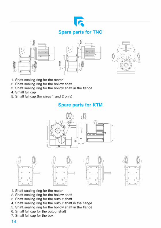
Spare parts for TNC
Spare parts for KTM
1. Shaft sealing ring for the motor
2. Shaft sealing ring for the hollow shaft
3. Shaft sealing ring for the hollow shaft in the flange
4. Small full cap
5. Small full cap (for sizes 1 and 2 only)
1. Shaft sealing ring for the motor
2. Shaft sealing ring for the hollow shaft
3. Shaft sealing ring for the output shaft
4. Shaft sealing ring for the output shaft in the flange
5. Shaft sealing ring for the hollow shaft in the flange
6. Small full cap for the output shaft
7. Small full cap for the box

15
11) Scrapping and Disposal:After service life expiry gearboxes shall be scrapped in compliance with respective regulations and
laws on waste, crude oil matters disposal to prevent threat of people and living environment.
Disassemble the gearbox classify its parts according to their material, remove lubricant and deliver
it to a specialised company for disposal
12) Guarantee:The guarantee is provided according to valid provisions of the Law No. 513/91 (of the
Commercial Code) in the wording of later regulations.
Cancellation of guarantee: in case the gearbox is used in defiance of the "Instructions of Use"
or incorrect intervention was carried out.
Final Quality Control shall comply with the ISO 9001:2000 directive and the quality manual.

16
Notes:
17
ACCEPTANCE CERTIFICATE
Job No.: ......................................................................................................
......................................................................................................
......................................................................................................
......................................................................................................
......................................................................................................
......................................................................................................
Serial No.: ......................................................................................................
......................................................................................................
......................................................................................................
......................................................................................................
......................................................................................................
......................................................................................................
......................................................................................................
Lubricant: ......................................................................................................
Final Quality Control Date: Checked by:

WIEN
TOS ZNOJMO, a. s.Družstevní 3669 02 ZnojmoCzech Republic
www.tos-znojmo.cz
Phone: 00420 515 288 111 00420 515 288 211 – 7Fax: 00420 515 288 201 00420 515 288 101e-mail: [email protected] gr
aph
ic d
esig
n&
prin
t: T
iská
rna
MLO
K s
.r.o.
, ww
w.m
lok.
net
2004
/I
Orientation plan of ZNOJMOOrientation plan of ZNOJMO
PRAHA
BRNO
WIEN