instructions for use oxylog 3000 plus - draeger · 2020-04-09 · instructions for use oxylog 3000...
TRANSCRIPT

Instructions for use
Oxylog 3000 plus
Emergency and Transport VentilatorSoftware 1.n
WARNINGTo properly use this medical device, read and comply with these instructions for use.
2 Instructions for use Oxylog 3000 plus SW 1.n
Typographical Conventions
Any text shown on the screen and any labeling on the device are printed in bold and italics, for example, PEEP, Air, or Alarm settings.
The "greater than" symbol > indicates the navigation path in a dialog window, for example, System configuration > Monitoring > Basic settings. In this example, System configuration represents the dialog window title, Monitoring represents a horizontally aligned tab, and Basic settings a vertically aligned tab.
Screen reproductions
The reproductions of screen content in the instructions for use can differ from the content actually shown on the screen.
Trademarks
Safety information definitions
1 Consecutive numbers indicate steps of action, with the numbering restarting with "1" for each new sequence of actions.
Bullet points indicate individual actions or differ-ent options for action.
– Dashes indicate the listing of data, options, or objects.
(A) Letters in parentheses refer to elements in the related illustration.
A Letters in illustrations denote elements referred to in the text.
Trademark Trademark owner
Oxylog® Dräger
AutoFlow® Dräger
DrägerService® Dräger
Sekusept® Ecolab
BIPAP1)
1) Trademark used under license
WARNINGA WARNING statement provides important information about a potentially hazardous situation which, if not avoided, could result in death or serious injury.
CAUTIONA CAUTION statement provides important information about a potentially hazardous situation which, if not avoided, may result in minor or moderate injury to the user or patient or in damage to the equipment or other property.
NOTEA NOTE provides additional information intended to avoid inconvenience during operation.

Instructions for use Oxylog 3000 plus SW 1.n 3
Definition of target groups
For this medical device, users, maintenance personnel, and experts are defined as target groups.
These target groups must have received instruction in the use of the medical device and must have the necessary training and knowledge to use, install, reprocess, maintain, or repair the product.
Dräger emphasizes that the medical device must be used, installed, reprocessed, maintained or repaired exclusively by the defined target groups.
Users
Users are intended operators as defined on page 14 hereof for the use of the medical device in accordance with its intended use.
Maintenance personnel
Maintenance personnel are persons who are responsible to the operating company for the maintenance of the product.
Maintenance personnel are persons authorized to install, reprocess or maintain the medical device.
Experts
Experts are persons who are authorized to perform repair or complex maintenance work on the medical device.
Abbreviations and symbols
For explanations refer to "Abbreviations" on page 23 and "Symbols" on page 24.

4 Instructions for use Oxylog 3000 plus SW 1.n
This page has been left blank intentionally.

Instructions for use Oxylog 3000 plus SW 1.n 5
Contents
Contents
For Your Safety and that of Your Patients . 7
General safety information . . . . . . . . . . . . . . . 8Product-specific safety information. . . . . . . . . 12
Use . . . . . . . . . . . . . . . . . . . . . . . . . . . . . . . . . 13
Intended use. . . . . . . . . . . . . . . . . . . . . . . . . . 14Indications/Contraindications . . . . . . . . . . . . . 14Environment of use. . . . . . . . . . . . . . . . . . . . . 14
System overview . . . . . . . . . . . . . . . . . . . . . 17
Basic unit with all options . . . . . . . . . . . . . . . . 18Range of functions . . . . . . . . . . . . . . . . . . . . . 22Abbreviations . . . . . . . . . . . . . . . . . . . . . . . . . 23Symbols . . . . . . . . . . . . . . . . . . . . . . . . . . . . . 24
Operating concept . . . . . . . . . . . . . . . . . . . . 27
Switching on and off . . . . . . . . . . . . . . . . . . . . 28Ventilation controls . . . . . . . . . . . . . . . . . . . . . 29Display operating controls . . . . . . . . . . . . . . . 30Additional function keys . . . . . . . . . . . . . . . . . 31On-screen window structure. . . . . . . . . . . . . . 32
Assembly. . . . . . . . . . . . . . . . . . . . . . . . . . . . 35
Internal rechargeable battery . . . . . . . . . . . . . 37Connecting the power supply . . . . . . . . . . . . . 38External power supply . . . . . . . . . . . . . . . . . . 39Connecting the gas supply . . . . . . . . . . . . . . . 41Connecting the reusable breathing circuit for adults . . . . . . . . . . . . . . . . . . . . . . . . . . . . . . . 43Connecting the disposable breathing circuit for adults . . . . . . . . . . . . . . . . . . . . . . . . . . . . . . . 45Connecting the disposable breathing circuit for pediatric patients . . . . . . . . . . . . . . . . . . . . . . 46Connecting a bacterial filter or HME. . . . . . . . 47Connecting the CO2 sensor and the cuvette . 48Attaching the Oxylog 3000 plus to standard rail systems . . . . . . . . . . . . . . . . . . . . . . . . . . . . . 49
Preparation . . . . . . . . . . . . . . . . . . . . . . . . . . 51
Charging the battery . . . . . . . . . . . . . . . . . . . . 52Determining the approximate pneumatic operating time. . . . . . . . . . . . . . . . . . . . . . . . . . . . . . . . . 53Checking readiness for operation. . . . . . . . . . 54
Performing the device check . . . . . . . . . . . . . 54CO2 zero calibration and filter check before ventila-tion (optional). . . . . . . . . . . . . . . . . . . . . . . . . 58Preparation for use after system check, CO2 zero calibration and CO2 filter check . . . . . . . . . . 60
Operation . . . . . . . . . . . . . . . . . . . . . . . . . . . 61
Starting operation . . . . . . . . . . . . . . . . . . . . . 62Preparing the ventilation mode . . . . . . . . . . . 64VC-CMV, VC-AC . . . . . . . . . . . . . . . . . . . . . . 65VC-SIMV, VC-SIMV/PS. . . . . . . . . . . . . . . . . 68PC-BIPAP, PC-BIPAP/PS . . . . . . . . . . . . . . . 70Spn-CPAP, Spn-CPAP/PS . . . . . . . . . . . . . . . 72Non-invasive ventilation (NIV) . . . . . . . . . . . . 75Special functions . . . . . . . . . . . . . . . . . . . . . . 76O2 concentration by "O2 blending" . . . . . . . . 78Setting the HME correction . . . . . . . . . . . . . . 79Calibration . . . . . . . . . . . . . . . . . . . . . . . . . . . 80Screen brightness . . . . . . . . . . . . . . . . . . . . . 80Alarm volume . . . . . . . . . . . . . . . . . . . . . . . . 80Shutdown . . . . . . . . . . . . . . . . . . . . . . . . . . . 81
Alarms . . . . . . . . . . . . . . . . . . . . . . . . . . . . . 83
Safety information . . . . . . . . . . . . . . . . . . . . . 84Alarm priorities . . . . . . . . . . . . . . . . . . . . . . . 84Alarm indication. . . . . . . . . . . . . . . . . . . . . . . 85Setting alarm limits . . . . . . . . . . . . . . . . . . . . 87
Monitoring . . . . . . . . . . . . . . . . . . . . . . . . . . 89
Displaying curves . . . . . . . . . . . . . . . . . . . . . 90Displaying measured values . . . . . . . . . . . . . 90CO2 measurement (optional) . . . . . . . . . . . . 91Data communication (optional) . . . . . . . . . . . 94
Configuration . . . . . . . . . . . . . . . . . . . . . . . . 95
Displaying configuration and information . . . 96Customer Service Mode . . . . . . . . . . . . . . . . 97Customer service manual . . . . . . . . . . . . . . . 108
Problem solving . . . . . . . . . . . . . . . . . . . . . 109
Alarm – Cause – Remedy . . . . . . . . . . . . . . . 110Messages in the alarm message field . . . . . . 110

Contents
6 Instructions for use Oxylog 3000 plus SW 1.n
Additional messages in the alarm message field . . . . . . . . . . . . . . . . . 117Messages in the information field. . . . . . . . . . 118Error messages during the device check . . . . 120
Cleaning, Disinfection and Sterilization . . . 121
Disassembly . . . . . . . . . . . . . . . . . . . . . . . . . . 122Information on reprocessing. . . . . . . . . . . . . . 125Reprocessing procedure . . . . . . . . . . . . . . . . 125Reprocessing list . . . . . . . . . . . . . . . . . . . . . . 129Assembling parts . . . . . . . . . . . . . . . . . . . . . . 129
Maintenance . . . . . . . . . . . . . . . . . . . . . . . . . 131
Maintenance intervals of Oxylog 3000 plus . . 132Inspection . . . . . . . . . . . . . . . . . . . . . . . . . . . . 133Safety checks . . . . . . . . . . . . . . . . . . . . . . . . . 133Preventive maintenance. . . . . . . . . . . . . . . . . 134Repair . . . . . . . . . . . . . . . . . . . . . . . . . . . . . . . 134In case of ventilator failure . . . . . . . . . . . . . . . 135
Disposal . . . . . . . . . . . . . . . . . . . . . . . . . . . . 137
Disposing of the medical device. . . . . . . . . . . 138Disposal instructions . . . . . . . . . . . . . . . . . . . 138
Technical data. . . . . . . . . . . . . . . . . . . . . . . . 139
Ambient conditions . . . . . . . . . . . . . . . . . . . . . 140Settings . . . . . . . . . . . . . . . . . . . . . . . . . . . . . 141Performance characteristics. . . . . . . . . . . . . . 142Measured values and curves display . . . . . . . 144Monitoring. . . . . . . . . . . . . . . . . . . . . . . . . . . . 145Operating data . . . . . . . . . . . . . . . . . . . . . . . . 146Device specifications . . . . . . . . . . . . . . . . . . . 148Materials used . . . . . . . . . . . . . . . . . . . . . . . . 150EMC declaration. . . . . . . . . . . . . . . . . . . . . . . 151
Description . . . . . . . . . . . . . . . . . . . . . . . . . . 155
Ventilation modes . . . . . . . . . . . . . . . . . . . . . . 156AutoFlow . . . . . . . . . . . . . . . . . . . . . . . . . . . . 160Dead space . . . . . . . . . . . . . . . . . . . . . . . . . . 162Determining cycle time, inspiratory time and expir-atory time . . . . . . . . . . . . . . . . . . . . . . . . . . . . 162Functional description . . . . . . . . . . . . . . . . . . 163
List of accessories . . . . . . . . . . . . . . . . . . . 165
Index . . . . . . . . . . . . . . . . . . . . . . . . . . . . . . . 167
Accessing Customer Service Mode . . . . . 171
Accessing Customer Service Mode . . . . . . . 172Accessing Customer Service Mode Oxylog 3000 plus SW 1.n . . . . . . . . . . . . . . . 173

Instructions for use Oxylog 3000 plus SW 1.n 7
For Your Safety and that of Your Patients
For Your Safety and that of Your Patients
General safety information . . . . . . . . . . . . . 8
Strictly follow these instructions for use . . . . . 8Maintenance. . . . . . . . . . . . . . . . . . . . . . . . . . 8Accessories . . . . . . . . . . . . . . . . . . . . . . . . . . 8Connected devices. . . . . . . . . . . . . . . . . . . . . 9Safe connection with other electrical equipment. . . . . . . . . . . . . . . . . . . . . . . . . . . . 9Patient safety . . . . . . . . . . . . . . . . . . . . . . . . . 9Patient monitoring. . . . . . . . . . . . . . . . . . . . . . 9Information on Electromagnetic Compatibility 9Functional safety . . . . . . . . . . . . . . . . . . . . . . 10Appropriate monitoring . . . . . . . . . . . . . . . . . . 10Connection to other devices. . . . . . . . . . . . . . 10
Product-specific safety information . . . . . . 12
Installing accessories . . . . . . . . . . . . . . . . . . . 12Only one copy of instructions for use included 12

For Your Safety and that of Your Patients
8 Instructions for use Oxylog 3000 plus SW 1.n
General safety information
The following WARNING and CAUTION statements apply to general operation of the medical device.
WARNING and CAUTION statements specific to subsystems or particular features of the medical device appear in the respective sections of these instructions for use or in the instructions for use of another product used with this medical device.
Strictly follow these instructions for use
Maintenance
Accessories
WARNING
Risk of incorrect operation and of incorrect use
Any use of the medical device requires full understanding and strict observation of all sections of these instructions for use. The medical device must only be used for the purpose specified under "Intended use" on page 14.
Strictly observe all WARNING and CAUTION statements throughout these instructions for use and all statements on medical device labels. Failure to observe these safety information statements constitutes a use of the medical device that is inconsistent with its intended use.
WARNING
Risk of medical device failure and of patient injury
The medical device must be inspected and serviced regularly by maintenance personnel. Repair and complex maintenance carried out on the medical device must be performed by experts.
If the above is not complied with, medical device failure and patient injury may occur. Observe chapter "Maintenance".
Dräger recommends that a service contract is obtained with DrägerService and that all repairs are performed by DrägerService. For maintenance Dräger recommends the use of authentic Dräger repair parts.
WARNING
Risk when using unauthorized accessories
If unauthorized accessories are used, patients may be put at risk due to malfunctions of the medical device. Only use the medical device together with authorized accessories listed in the current list of accessories.

Instructions for use Oxylog 3000 plus SW 1.n 9
For Your Safety and that of Your Patients
Connected devices
Safe connection with other electrical equipment
Patient safety
The design of the medical device, the accompanying literature, and the labeling on the medical device are based on the assumption that the use of the equipment is restricted to trained professionals, and that certain inherent characteristics of the medical device are known to the trained user. Instructions, warnings, and caution statements are therefore largely limited to the specifics of the Dräger design.
This publication excludes references to various hazards which are obvious to a medical professional and user of this medical device, to the consequences of medical device misuse, and to potentially adverse effects in patients with abnormal conditions.
Medical device modification or misuse can be dangerous.
Patient monitoring
The users of the medical device are responsible for choosing appropriate safety monitoring that provides adequate information on medical device performance and patient condition.
Patient safety may be achieved through a wide variety of means, ranging from electronic surveillance of medical device performance and patient condition, to simple, direct observation of clinical signs.
The responsibility for the selection of the best level of patient monitoring lies solely with the medical device user.
Information on Electromagnetic Compatibility
General information on electromagnetic compatibility (EMC) pursuant to international EMC standard IEC 60601-1-2:
Electromedical devices are subject to special precautionary measures concerning electromagnetic compatibility (EMC) and must be installed and put into operation in accordance with the EMC information. Refer to section "EMC declaration" on page 151.
WARNING
Risk of electric shock and of device malfunction
Any connected devices or device combination not complying with the requirements set out in these instructions for use may compromise the correct functioning of the medical device and lead to an electric shock. Before operating the medical device, strictly comply with the instructions for use of all connected devices or device combinations.
WARNING
Risk of patient injury
Electrical connections to equipment not listed in these instructions for use or these Assembly Instructions must only be made when approved by each respective manufacturer.
WARNING
Risk of patient injury
Do not make therapeutic decisions based solely on individual measured values and monitoring parameters.
WARNING
Do not use portable and mobile HF communications equipment, e.g., mobile phones, in the vicinity of the medical device.

For Your Safety and that of Your Patients
10 Instructions for use Oxylog 3000 plus SW 1.n
Functional safety
The essential performance of the Oxylog 3000 plus is defined as:
Appropriate delivery of ventilation to the patient-connection port or generation of an alarm condition.
Appropriate monitoring
The monitoring functionality of the Oxylog 3000 plus ensures appropriate monitoring of ventilation therapy. To ensure appropriate monitoring during ventilation, always set alarm limits for the following parameters:
– Airway pressure, Paw
– Expiratory minute volume, MVe
– Respiratory rate (if applicable), RR
– etCO2 (if applicable)
If appropriate alarm limits are not set, alarms may not be triggered in the following cases:
– Acute changes in the patient’s condition
– Incorrect settings and faulty handling
– Hose system leakage
Connection to other devices
Device combinations (Dräger devices + Dräger devices or Dräger devices + third-party devices) approved by Dräger (see instructions for use of the individual devices) comply with the following standards:
– IEC 60601-1 (3rd edition)Medical electrical equipmentPart 1-1: General requirements for safety and essential performance
– IEC 60601-1-2Medical electrical equipmentPart 1-2: General requirements for safety and essential performanceCollateral standard: Electromagnetic compatibility – Requirements and tests
– IEC 60601-1-8Medical electrical equipmentPart 1-8: General requirements for safetyCollateral standard: General requirements, tests, and guidance for alarm systems in medical equipment and medical electrical systems
– IEC 60601-1 (2nd edition)Medical electrical equipmentPart 1: General requirements for safety
– IEC 60601-1-1Medical electrical equipmentPart 1-1: General requirements for safetyCollateral standard: Safety requirements for medical electrical systems
– IEC 60601-1-2Medical electrical equipmentPart 1-2: General requirements for safetyCollateral standard: Electromagnetic compatibility; Requirements and tests
– IEC 60601-1-4Medical electrical equipmentPart 1-4: General requirements for safetyCollateral standard: Programmable electrical medical systems
CAUTION
Always use a separate SpO2 monitor for patients who are dependent on an exact O2 concentration.

Instructions for use Oxylog 3000 plus SW 1.n 11
For Your Safety and that of Your Patients
– IEC 60601-1-8Medical electrical equipmentPart 1-8: General requirements for safetyCollateral standard: General requirements, tests, and guidance for alarm systems in medical electrical equipment and medical electrical systems
If a device combination is not approved by Dräger, proper operation of the devices can be compromised.
The user must ensure that the device combination meets the applicable standards.
Strictly observe instructions for use and assembly instructions of all connected devices.

For Your Safety and that of Your Patients
12 Instructions for use Oxylog 3000 plus SW 1.n
Product-specific safety information
Installing accessories
Strictly follow the assembly instructions and instructions for use.
Only one copy of instructions for use included
WARNING
Ventilation monitoring is mandatory at all times! Whenever a patient is connected to the ventilator, constant attention by qualified medical staff is required in order to provide immediate corrective action in case of a malfunction.
The user must not solely rely on the built-in monitoring of the ventilator and must always assume full responsibility for proper ventilation and patient safety in all situations.
WARNING
Keep an manual resuscitator at the ready
If a malfunction is detected in the ventilator and its life-support functions can no longer be guaranteed (such as in case of a power supply failure or interruption in the compressed gas supply), ventilation must be started without delay with an independent ventilator (manual resuscitator) – using PEEP and/or increased inspired O2 concentration as necessary.
WARNING
Risk of CO2 rebreathing
To ensure proper ventilation when setting the ventilation parameters, the total dead space volume of the breathing circuit must be considered. This applies particularly when using low tidal volumes. Observe for signs of rebreathing.
WARNING
Risk of malfunction
Unauthorized modification of the medical device will result in malfunction.
This medical device must not be modified without the permission of Dräger.
CAUTION
An etCO2 value by itself is insufficient as a basis for medical decisions.
CAUTION
Installations on the Oxylog 3000 plus must be done in accordance with these instructions for use. Make sure that the connections are securely fitted onto the basic unit system.
CAUTION
Only one copy of the instructions for use is included per device, and it must therefore be kept in an accessible location for users.

Instructions for use Oxylog 3000 plus SW 1.n 13
Use
Use
Intended use . . . . . . . . . . . . . . . . . . . . . . . . . 14
Indications/Contraindications . . . . . . . . . . . 14
Environment of use . . . . . . . . . . . . . . . . . . . 14

Use
14 Instructions for use Oxylog 3000 plus SW 1.n
Intended use
The Oxylog 3000 plus is a time-cycled, volume-controlled and pressure-controlled emergency and transport ventilator for patients requiring mandatory or assisted ventilation with a tidal volume from 50 mL upwards.
Intended user: the device is intended for use by and under the supervision of trained healthcare professionals, e.g. doctors, nurses, emergency medical technicians, respiratory therapists, and paramedics.
Indications/Contraindications
For patients with tidal volume of 50 mL upwards.
Environment of use
Intended environment of use:
– Mobile use for emergency patients, in both outdoor and indoor environments.
– During transport in ambulances or aircraft, including helicopters.
– In accident and emergency departments.
– When moving ventilated patients around the hospital.
– In the recovery room.
WARNING
The Oxylog 3000 plus ventilator must only be used under the supervision of qualified medical personnel in order to provide immediate corrective action in case of a malfunction.
WARNING
Only use the device under the permissible ambient conditions and supply conditions. Otherwise, the device may not be functional and may fail.
WARNING
Do not use the device in hyperbaric chambers.
The medical device may malfunction, causing danger to the patient.

Instructions for use Oxylog 3000 plus SW 1.n 15
Use
WARNING
Do not use the device in conjunction with magnetic resonance imaging (MRI, NMR, NMI).
The medical device may malfunction, causing danger to the patient.
WARNING
Risk of explosion and fire
This device is neither approved nor certified for use in areas where oxygen concentrations above 25 Vol% or combustible or explosive gas mixtures are likely to occur.
WARNING
In toxic surroundings:– The patient must be ventilated with 100 %
medical grade oxygen so that toxic constituents do not enter into the breathing gas.
– The patient must be immediately transferred to a breathable atmosphere in order to prevent inhalation of toxic air when spontaneous breathing resumes.
WARNING
In infectious environments:– The patient must be ventilated with 100 %
medical grade oxygen so that bacteria, viruses, fungi or spores do not enter the breathing gas.
– The patient must be immediately transferred to a breathable atmosphere in order to prevent inhalation of infectious air when spontaneous breathing resumes.

16 Instructions for use Oxylog 3000 plus SW 1.n
This page has been left blank intentionally.

Instructions for use Oxylog 3000 plus SW 1.n 17
System overview
System overview
Basic unit with all options . . . . . . . . . . . . . . 18
Side view, right . . . . . . . . . . . . . . . . . . . . . . . . 19Rear view . . . . . . . . . . . . . . . . . . . . . . . . . . . . 19Reusable breathing circuit for adults . . . . . . . 20Disposable breathing circuit for adults . . . . . . 20Disposable breathing circuit for pediatric patients . . . . . . . . . . . . . . . . . . . . . . . . . . . . . . 21
Range of functions . . . . . . . . . . . . . . . . . . . . 22
Ventilation functions of the Oxylog 3000 plus. 22
Abbreviations . . . . . . . . . . . . . . . . . . . . . . . . 23
Symbols. . . . . . . . . . . . . . . . . . . . . . . . . . . . . 24
System overview
18 Instructions for use Oxylog 3000 plus SW 1.n
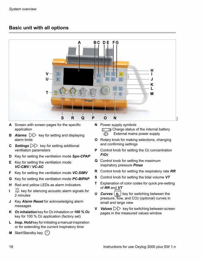
Basic unit with all options
A Screen with screen pages for the specific application
B Alarms key for setting and displaying alarm limits
C Settings key for setting additional ventilation parameters
D Key for setting the ventilation mode Spn-CPAP
E Key for setting the ventilation mode VC-CMV / VC-AC
F Key for setting the ventilation mode VC-SIMV
G Key for setting the ventilation mode PC-BIPAP
H Red and yellow LEDs as alarm indicators
I key for silencing acoustic alarm signals for 2 minutes
J Key Alarm Reset for acknowledging alarm messages
K O2 inhalation key for O2 inhalation or 100 % O2 key for 100 % O2 application (factory set)
L Insp. Hold key for initiating a manual inspiration or for extending the current inspiratory time
M Start/Standby key
N Power supply symbols Charge status of the internal battery External mains power supply
O Rotary knob for making selections, changing and confirming settings
P Control knob for setting the O2 concentration FiO2
Q Control knob for setting the maximum inspiratory pressure Pmax
R Control knob for setting the respiratory rate RR
S Control knob for setting the tidal volume VT
T Explanation of color codes for quick pre-setting of RR and VT
U Curves key for switching between the pressure, flow, and CO2 (optional) curves in small and large view
V Values key for switching between screen pages in the measured values window
Fro
nt
A BC D E FG
HIJKLM
NOPQRS
T
UV
CurvesCurves
Instructions for use Oxylog 3000 plus SW 1.n 19
System overview
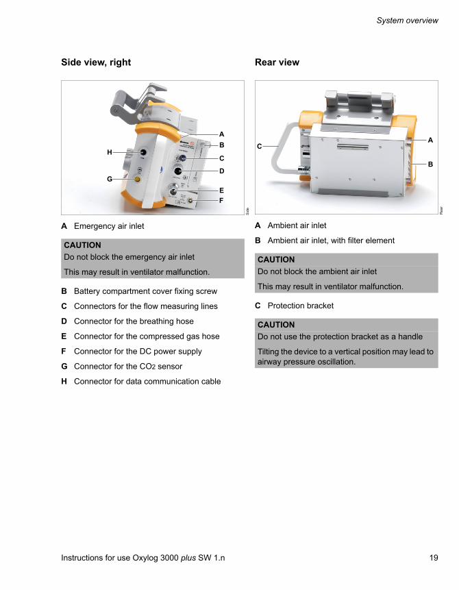
Side view, right
A Emergency air inlet
B Battery compartment cover fixing screw
C Connectors for the flow measuring lines
D Connector for the breathing hose
E Connector for the compressed gas hose
F Connector for the DC power supply
G Connector for the CO2 sensor
H Connector for data communication cable
Rear view
A Ambient air inlet
B Ambient air inlet, with filter element
C Protection bracket
Sid
eCAUTION
Do not block the emergency air inlet
This may result in ventilator malfunction.
B
C
D
EF
A
G
H
Re
ar
CAUTION
Do not block the ambient air inlet
This may result in ventilator malfunction.
CAUTION
Do not use the protection bracket as a handle
Tilting the device to a vertical position may lead to airway pressure oscillation.
A
B
C
System overview
20 Instructions for use Oxylog 3000 plus SW 1.n
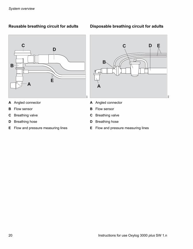
Reusable breathing circuit for adults
A Angled connector
B Flow sensor
C Breathing valve
D Breathing hose
E Flow and pressure measuring lines
Disposable breathing circuit for adults
A Angled connector
B Flow sensor
C Breathing valve
D Breathing hose
E Flow and pressure measuring lines
00
1A
E
B
CD
00
2
EDC
A
B
Instructions for use Oxylog 3000 plus SW 1.n 21
System overview
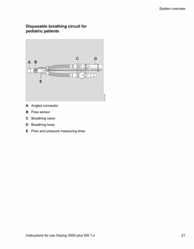
Disposable breathing circuit for pediatric patients
A Angled connector
B Flow sensor
C Breathing valve
D Breathing hose
E Flow and pressure measuring lines
08
13
71
70
DA
E
CB

System overview
22 Instructions for use Oxylog 3000 plus SW 1.n
Range of functions
Ventilation functions of the Oxylog 3000 plus
Ventilation modes:
– Volume-controlled ventilation:
– VC-CMV / VC-AC,
– VC-SIMV.
– Pressure-controlled ventilation:
– PC-BIPAP
– Support of spontaneous breathing:
– Spn-CPAP
Additional settings for ventilation:
– Pressure Support: in the ventilation modesVC-SIMV, PC-BIPAP, and Spn-CPAP,
– Apnea ventilation: in the ventilation mode SpnCPAP,
– AutoFlow (optional): in the ventilation modes VC-CMV, VC-AC and VC-SIMV.
– NIV: in the ventilation modes: Spn-CPAP (/PS), PC-BIPAP (/PS), VC-CMV / AF, VC-AC / AF, and VC-SIMV / AF.
Special functions:
– Inspiration hold,
– O2 inhalation (optional), with an inhalation mask – 100 % O2 (optional)
For a detailed description of the ventilation modes and the additional settings, refer to "Description" on page 155. For abbreviations, see "Abbreviations" on page 23.
NOTE
In these instructions for use the unit of measurement for airway pressure is expressed in [mbar]. However, in some languages the display of the Oxylog 3000 plus shows [cmH2O].
1 [mbar] equals approximately 1 [cmH2O].

Instructions for use Oxylog 3000 plus SW 1.n 23
System overview
Abbreviations
Abbreviation Explanation
100 % O2 100 % O2 flow
AF AutoFlow
ATPD Ambient Temperature and Pressure, Dry (ambient temperature and pressure, dry)
BF Body Floating
bpm Breaths per minute
BTPS Body Temperature and Pressure, Saturated. Measured values referred to the conditions of the patient's lungs, body temperature 37 °C, airway pressure, vapor-saturated gas.
C Compliance
CO2 Carbon dioxide
CSM Customer Service Mode
Psupp Positive pressure above PEEP
EMC Electromagnetic Compatibility
ESD Electrostatic Discharge
etCO2 Endtidal CO2 concentration
RR Respiratory rate
RRapn Respiratory rate during apnea ventilation
FiO2 Inspiratory oxygen concentration
FRC Functional Residual Capacity
RRsp Spontaneous breathing rate
HME Heat and Moisture Exchanger (heat and moisture exchanger)
I:E Ratio of inspiratory time toexpiratory time
IPX2 Ingress Protection level 2
IPX4 Ingress Protection level 4
MEDIBUS.X Dräger communications protocol for medical devices with uniform data definition for all devices
MVe Total expiratory minute volume
MVespon Spontaneous breathing portion of the expiratory minute volume
MVi Total inspiratory minute volume
NIV Non-invasive ventilation – mask ventilation
O2 Oxygen
O2 inhalat. O2 inhalation
Paw Airway pressure
PC-BIPAP Pressure Controlled – Biphasic Positive Airway Pressure (spontaneous breathing under continuous positive airway pressure with 2 different pressure levels)
PEEP Positive End-Expiratory Pressure
PIF Peak Inspiratory Flow
Pinsp Inspiratory pressure
PIP Peak Inspiratory Pressure
Pmax Maximum airway pressure
Pmean Mean airway pressure
Pplat Plateau pressure
PS Pressure Support (pressure-sup-ported spontaneous breathing)
R Resistance
RF Radio Frequency
Spn-CPAP Spontaneous Continuous Positive Airway Pressure (spontaneous breathing with continuous positive pressure level)
SpO2 Saturation of peripheral oxygen
Tapn Time before apnea is recognized
Te Expiratory time
Ti Inspiratory time
Tplat% Plateau time in % of inspiratory time
Abbreviation Explanation

System overview
24 Instructions for use Oxylog 3000 plus SW 1.n
Symbols
UN United Nations
VC-AC Volume-Controlled – Assisted-Controlled ventilation
VC-CMV Volume Controlled – Controlled Mandatory Ventilation
VC-SIMV. Volume Controlled – Synchronized Intermittent Mandatory Ventilation
VT Tidal volume
VTapn Tidal volume during apnea ventilation
VTe Expiratory tidal volume
VTi Inspiratory tidal volume
Abbreviation Explanation
Symbol Explanation
Key for initiating a manual inspiration or for extending the current inspiratory time
Key for setting additional ventilation parameters
Key for setting and displaying alarm limits
Key for displaying measured values
Key for switching between the pressure, flow, and CO2 (optional) curves in small and large view
Key for silencing acoustic alarm signals for 2 minutes
Key for acknowledging alarm messages
Rotary knob
Insp.hold
Settings
Alarms
Values
Curves
AlarmReset
Start / Standby key
Upper alarm limit
Lower alarm limit
! Low-priority alarm message
!! Medium-priority alarm message
!!! High-priority alarm message
* Trigger indicator
Attention! Consult accompanyingdocuments
Protection class type BF (Body Floating), defibrillator-proof
Charge status of the internal battery
Symbol Explanation

Instructions for use Oxylog 3000 plus SW 1.n 25
System overview
Mains power supply connected
Battery charge (example: three quarters full)
Class II equipment, device protected against electric shock with additional safety precautions such as double or reinforced insulations, without protective earthing.
Do not dispose of the device as municipal waste.
Manufacturing date
Manufacturer
DC input
Operating instructions
Warning! Strictly follow these instructions for use
For dry locations only
Warning, dangerous voltage!
Temperature limitations
Latex free
Symbol Explanation
Do not reuse
Keep oil and grease free
Non-sterile
Keep away from sunlight
For indoor use only
Do not open
Prohibition: Do not obstruct the emergency air inlet or the ambient air inlet.
Pediatric
Adult
Slope (steep, medium, flat)
Quantity
Do not use if package is damaged
Ambient pressure
Symbol Explanation
Pediatric
Adult

System overview
26 Instructions for use Oxylog 3000 plus SW 1.n
Relative humidity
Part number
Lot number
Recycling in accordance with the regulations for lithium-ion batteries.
UN Regulation No. 10, revision 3 (EMC)
Symbol Explanation
E 13 10 R - 03XXXX

Instructions for use Oxylog 3000 plus SW 1.n 27
Operating concept
Operating concept
Switching on and off . . . . . . . . . . . . . . . . . . 28
Switching on . . . . . . . . . . . . . . . . . . . . . . . . . . 28Switching off . . . . . . . . . . . . . . . . . . . . . . . . . . 28
Ventilation controls . . . . . . . . . . . . . . . . . . . 29
Display operating controls . . . . . . . . . . . . . 30
Additional function keys . . . . . . . . . . . . . . . 31
On-screen window structure . . . . . . . . . . . . 32
Operating concept
28 Instructions for use Oxylog 3000 plus SW 1.n
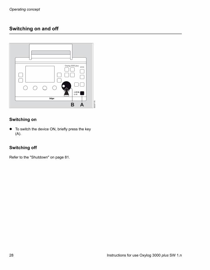
Switching on and off
Switching on
To switch the device ON, briefly press the key (A).
Switching off
Refer to the "Shutdown" on page 81.
00
33
71
70
Oxylog 3000 plus
AB

Instructions for use Oxylog 3000 plus SW 1.n 29
Operating concept
Ventilation controls
Controls for ventilation settings
A Keys for selecting the ventilation modes:
– VC-CMV / VC-AC,
– VC-SIMV,
– Spn-CPAP,
– PC-BIPAP.
B Rotary knob
C Ventilation parameter controls:
– Inspiratory tidal volume VT [mL],
– Respiratory rate RR [/min],
– Maximum inspiratory pressure Pmax [mbar],
– Inspiratory O2 concentration FiO2 [%].
Setting ventilation modes
Press the appropriate ventilation mode key (A) for approximately 3 seconds.
Or
1 Press the appropriate ventilation mode key (A).
2 Press the rotary knob (B) to confirm.
The selected ventilation mode will be activated.
The active ventilation mode is displayed in the upper left corner of the display (C).
00
13
71
70
BC
AOxylog 3000 plus
08
53
71
70
Oxylog 3000 plus
BC
A

Operating concept
30 Instructions for use Oxylog 3000 plus SW 1.n
Display operating controls
A Rotary knob for making selections, changing and confirming settings.
B Values key for switching between screen pages in the measured values window
C Curves key for switching between the pressure, flow, and CO2 (optional) curves in small and large views
D Settings key for displaying ventilation parameters (ventilation screen) in the settings window and for switching between screen pages
E Alarms key for displaying the alarm settings in the alarms window and for switching between screen pages
00
23
71
70
NOTE
Different parameters can be set on the display via the rotary knob (e. g. Ti, PEEP, Psupp, Pinsp).– To select the parameter: turn rotary knob.– To activate the parameter: press the rotary
knob.– To set the value: turn rotary knob.– To confirm the value: press the rotary knob.
Oxylog 3000 plus
B C
DE
A
CurvesCurves

Instructions for use Oxylog 3000 plus SW 1.n 31
Operating concept
Additional function keys
Additional keys are positioned on the right side of the front panel:
A Key for silencing acoustic alarm signals for 2 minutes.
B Alarm Reset key for acknowledging alarm messages.
C Insp. Hold key for initiating a manual inspiration or for extending the current inspiratory time.
D O2 inhalation key for O2 inhalation or 100 % O2 key for 100 % O2 application (factory set).
03
23
71
70
Oxylog 3000 plus
ABCD

Operating concept
32 Instructions for use Oxylog 3000 plus SW 1.n
On-screen window structure
General window structure
A Ventilation mode field
B Status and alarm messages field
C Measured values window
D Curve windowD and E are combined for a large curve screen.
E Window for settings or alarms
F Information window. For information on the content, refer to "Messages in the information field" on page 118.
Measured values window
A Parameter measured
B Measured value
C Unit of measurement
D Measured values (1st page of 7 available pages)If the CO2 option is not selected:1st page of 6 available pages
E Trigger indicator.
The last page shows an overview of all measured values.
05
43
71
71
A B
D
C
E F 05
83
71
71
15
63
71
71
BA D
E
C

Instructions for use Oxylog 3000 plus SW 1.n 33
Operating concept
Settings window
A Menu for setting supplementary ventilation parameters in accordance with the desired ventilation mode.
– AutoFlow (optional)
– Brightness
– CO2 filter check (optional)
– CO2 zero calibration (optional)
– CO2 cuvette type (optional)
– HME correction
– Hose type
– I:E / Ti
– NIV
– PEEP
– Pinsp
– RRapn and VTapn
– Slope
– Tapn
– Tplat
– Trigger
– Psupp
B Number of pages (1st page of 3 available pages)
Press Settings key. The pages are displayed consecutively.
Alarms window
A Menu for alarm limits and alarm parameters. For detailed operating instructions, see "Setting alarm limits" on page 87.
B Number of pages (1st page of 2 available pages)
To advance to the next page:
Press the Alarms key.The pages are displayed consecutively.
05
73
71
71
BA
10
93
71
71
A B

Operating concept
34 Instructions for use Oxylog 3000 plus SW 1.n
Enlarged view of pressure curve
Curve window showing the airway pressure curve Paw.
Press Curves key multiple times.
Enlarged view of flow curve
Curve window showing the flow curve.
Enlarged view of CO2 curve
Curve window showing the CO2 curve.
05
53
71
71
05
63
71
71
15
43
71
71
CurvesCurves

Instructions for use Oxylog 3000 plus SW 1.n 35
Assembly
Assembly
Internal rechargeable battery . . . . . . . . . . . 37
Removing the battery . . . . . . . . . . . . . . . . . . . 37Checking the charge status of the battery . . . 37Inserting the battery . . . . . . . . . . . . . . . . . . . . 37
Connecting the power supply . . . . . . . . . . . 38
External power supply . . . . . . . . . . . . . . . . . . 38
External power supply . . . . . . . . . . . . . . . . . 39
External power supply with DC/DC converter 39External power supply with AC/DC power pack (mains voltage) . . . . . . . . . . . . . . . . . . . 40
Connecting the gas supply . . . . . . . . . . . . . 41
Supply from an O2 cylinder. . . . . . . . . . . . . . . 41O2 supply from a central gas supply system . 42
Connecting the reusable breathing circuit for adults . . . . . . . . . . . . . . . . . . . . . . . . . . . . 43
Assembling the breathing valve . . . . . . . . . . . 43Connecting the breathing hoses and flow measuring lines . . . . . . . . . . . . . . . . . . . . . . . 44
Connecting the disposable breathing circuit for adults . . . . . . . . . . . . . . . . . . . . . . 45
Connecting the disposable breathing circuit for pediatric patients . . . . . . . . . . . . 46
Connecting a bacterial filter or HME. . . . . . 47
Adult reusable hose . . . . . . . . . . . . . . . . . . . . 47Adult disposable hose . . . . . . . . . . . . . . . . . . 47Disposable pediatric hose . . . . . . . . . . . . . . . 47
Connecting the CO2 sensor and the cuvette . . . . . . . . . . . . . . . . . . . . . . . . . . . . . . 48
Attaching the Oxylog 3000 plus to standard rail systems. . . . . . . . . . . . . . . . . . 49
Assembly
36 Instructions for use Oxylog 3000 plus SW 1.n
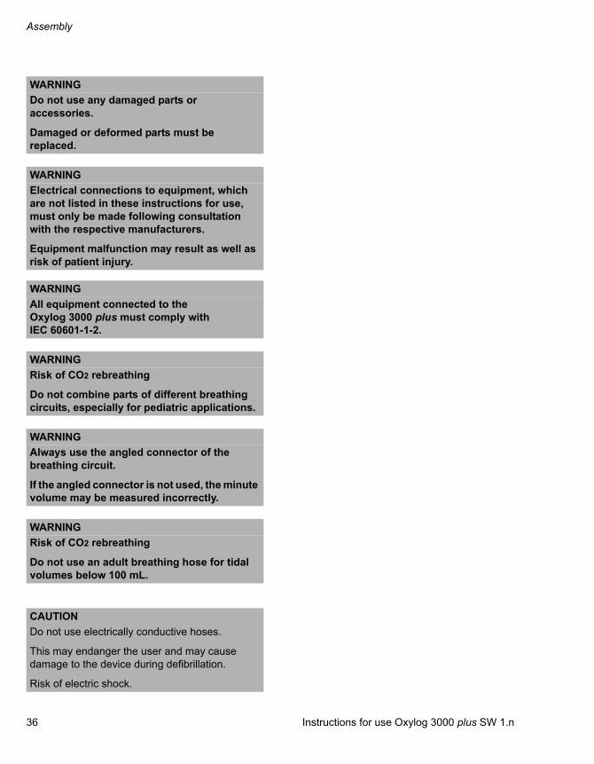
WARNING
Do not use any damaged parts or accessories.
Damaged or deformed parts must be replaced.
WARNING
Electrical connections to equipment, which are not listed in these instructions for use, must only be made following consultation with the respective manufacturers.
Equipment malfunction may result as well as risk of patient injury.
WARNING
All equipment connected to the Oxylog 3000 plus must comply with IEC 60601-1-2.
WARNING
Risk of CO2 rebreathing
Do not combine parts of different breathing circuits, especially for pediatric applications.
WARNING
Always use the angled connector of the breathing circuit.
If the angled connector is not used, the minute volume may be measured incorrectly.
WARNING
Risk of CO2 rebreathing
Do not use an adult breathing hose for tidal volumes below 100 mL.
CAUTION
Do not use electrically conductive hoses.
This may endanger the user and may cause damage to the device during defibrillation.
Risk of electric shock.

Instructions for use Oxylog 3000 plus SW 1.n 37
Assembly
Internal rechargeable battery
Internal power is provided by means of a removable rechargeable battery. For technical information, refer to "Technical data" on page 139.
Removing the battery
1 Turn the knob (C) on the battery compartment cover (B) counterclockwise to release the cover.
2 Open the battery cover.
3 Remove the battery (A) by pulling the tab.
Checking the charge status of the battery
Press the button on the rechargeable battery.The charge status is indicated by four LEDs.
Inserting the battery
1 Insert the battery into the battery compartment.
2 Close the battery cover.
3 Tighten the knob by turning it.
01
5A
B
C
CAUTION
The Oxylog 3000 plus will interrupt ventilation when the battery is replaced while the device is switched on and the external power supply is not connected. Ventilation will always resume with the last value settings approximately 3 seconds after inserting a recharged battery.
Assembly
38 Instructions for use Oxylog 3000 plus SW 1.n
Connecting the power supply
External power supply
To recharge the battery and to extend the operating time, use one of the following:
– DC/DC converter, or
– AC/DC power pack.
For more information refer to page 146.
Always position the device so that the external power connector can be easily disconnected from the ventilator.
WARNING
A fully charged battery must always be installed for safety reasons, even when operating from an external power supply.
WARNING
Risk of patient injury
Without a charged battery installed, ventilation will be interrupted in case of an external power supply failure.
It is recommended to have a fully charged spare battery available each time when using the Oxylog 3000 plus.

Instructions for use Oxylog 3000 plus SW 1.n 39
Assembly
External power supply
External power supply with DC/DC converter
The DC/DC converter must be used to connect the Oxylog 3000 plus to on-board power supply systems, e.g., in ambulances. It can be used with the following voltages: 12 VDC, 24 VDC or 28 VDC. The on-board power supply must be protected by a 10 to 16 A DC fuse.Outside this range the Oxylog 3000 plus cannot use the DC input power.
Mount the DC/DC converter on a flat wall and make sure the wall is solid enough to support the bracket. Use all 4 mounting holes (screw size M4).
1 Plug the large connector (A) of the DC/DC converter into the on-board supply.
2 Plug the small connector (B) into the DC connector (C) of the Oxylog 3000 plus.
3 When the Oxylog 3000 plus is correctly connected to an external power supply, the indicator (D) lights up.
WARNING
The DC/DC converter must be used in dry locations only.
Risk of electric shock and damage to the device.
01
6
Oxylog 3000 plus
12 VDC24 VDC28 VDC
D B
A
C
Assembly
40 Instructions for use Oxylog 3000 plus SW 1.n
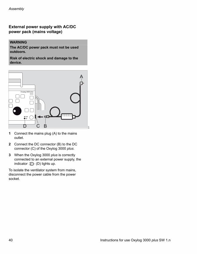
External power supply with AC/DC power pack (mains voltage)
1 Connect the mains plug (A) to the mains outlet.
2 Connect the DC connector (B) to the DC connector (C) of the Oxylog 3000 plus.
3 When the Oxylog 3000 plus is correctly connected to an external power supply, the indicator (D) lights up.
To isolate the ventilator system from mains, disconnect the power cable from the power socket.
WARNING
The AC/DC power pack must not be used outdoors.
Risk of electric shock and damage to the device.
01
7
O xylog 3000 plus
A
BD C

Instructions for use Oxylog 3000 plus SW 1.n 41
Assembly
Connecting the gas supply
Caution when handling O2: Supply from an O2 cylinder
1 Connect the pressure regulator (270 to 600 kPa outlet pressure, 500 kPa nominal pressure) to the O2 cylinder.
WARNING
Risk of explosion
Protect the O2 cylinder against tipping over. Keep away from excessive heat.
WARNING
Risk of fire
Do not grease or lubricate O2 fittings, such as cylinder valves and pressure reducers and do not handle with greasy hands.
WARNING
Operate cylinder valves by hand and rotate slowly to prevent the risk of fire or explosion.
Do not use tools.
WARNING
Only use medical grade oxygen.
WARNING
Always provide adequate ventilation in the area where the ventilator is being operated, in order to maintain ambient O2 concentration below 25 %, to prevent risk of fire.
WARNING
No smoking or open flames.
O2 enhances combustion of other substances and can intensify fires.
WARNING
Always use gas cylinders and pressure regulators that comply with all applicable regulations.
WARNING
Risk of suffocation
Always use filled O2 cylinders.
WARNING
Use only a pressure reducer with a blow-off valve at the outlet that limits the outlet pressure to a maximum of 1000 kPa in case of a malfunction, to prevent damage to the ventilator due to excessive O2 supply pressure on the input.

Assembly
42 Instructions for use Oxylog 3000 plus SW 1.n
2 Connect the O2 compressed gas hose (A) to the Oxylog 3000 plus.
3 Connect the O2 compressed gas hose to the pressure reducer (B).
4 Rotate the cylinder valve (C) slowly and open fully.
O2 supply from a central gas supply system
1 Connect the O2 compressed gas hose (A) to the Oxylog 3000 plus.
2 Connect the gas probe (B) to the O2 terminal unit until it has properly engaged and the supply of O2 is assured.
01
8
WARNING
Risk of ventilator malfunction
Do not install flow control valves or flowmeters in the gas supply to the Oxylog 3000 plus.
WARNING
Always check the O2 pressure of cylinder before use, to prevent insufficient oxygen supply during use.
O2
A
B
C
01
9
A
B
Instructions for use Oxylog 3000 plus SW 1.n 43
Assembly
Connecting the reusable breathing circuit for adults
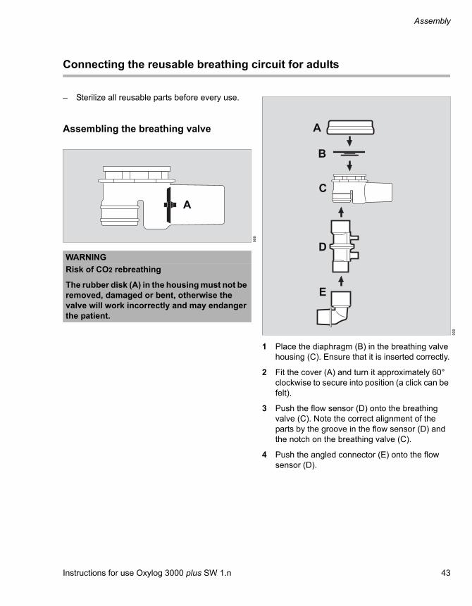
– Sterilize all reusable parts before every use.
Assembling the breathing valve
1 Place the diaphragm (B) in the breathing valve housing (C). Ensure that it is inserted correctly.
2 Fit the cover (A) and turn it approximately 60° clockwise to secure into position (a click can be felt).
3 Push the flow sensor (D) onto the breathing valve (C). Note the correct alignment of the parts by the groove in the flow sensor (D) and the notch on the breathing valve (C).
4 Push the angled connector (E) onto the flow sensor (D).
00
8WARNING
Risk of CO2 rebreathing
The rubber disk (A) in the housing must not be removed, damaged or bent, otherwise the valve will work incorrectly and may endanger the patient.
A
00
9
A
B
C
D
E

Assembly
44 Instructions for use Oxylog 3000 plus SW 1.n
Connecting the breathing hoses and flow measuring lines
1 Connect the breathing hose (A) to the breathing valve.
2 Connect the flow measuring lines (B) to the nozzles of the flow sensor. When connecting the flow measuring lines, pay attention to the differing diameters of the hoses and nozzles and connect them on the correct side.
3 Connect the flow measuring lines (B) to the Oxylog 3000 plus. Correct alignment is indicated by a notch on the connector, which must point away from the breathing hose. If it is incorrectly seated, incorrect values will be measured.
4 Connect the breathing hose (A) to the gas outlet on the Oxylog 3000 plus.
When connecting a breathing hose, check that the hose setting in the settings window corresponds to the connected hose.0
110
12
A
BB
A
B

Instructions for use Oxylog 3000 plus SW 1.n 45
Assembly
Connecting the disposable breathing circuit for adults
1 Connect the flow measuring lines (A) to the Oxylog 3000 plus. Correct alignment is indicated by a notch on the connector, which must point away from the breathing hose. If it is incorrectly seated, incorrect values will be measured.
2 Connect the breathing hose (B) to the gas outlet on the Oxylog 3000 plus.
When connecting a breathing hose, check that the hose setting in the settings window corresponds to the connected hose.
NOTE
Using a disposable hose may reduce the risk of cross-infection.
01
3
NOTE
Disposable hoses are shipped clean but non-sterile.
A
B

Assembly
46 Instructions for use Oxylog 3000 plus SW 1.n
Connecting the disposable breathing circuit for pediatric patients
If the ventilation volume is less than 250 mL, use a pediatric breathing circuit.
If the ventilation volume is more than 250 mL, use an adult breathing circuit.
1 Connect the blue flow measuring line (B) to the blue labeled connector.
2 Connect the transparent flow measuring line (A) to the other connector.
3 Connect the breathing hose (C) to the gas outlet on the Oxylog 3000 plus.
When connecting a breathing hose, check that the hose setting in the settings window corresponds to the connected hose.
01
3
B
C
A

Instructions for use Oxylog 3000 plus SW 1.n 47
Assembly
Connecting a bacterial filter or HME
The flow and volume measurements can be corrected for use with an HME. Refer to the "Setting the HME correction" on page 79.
Connect the bacterial filter or HME to the angled connector as follows.
Adult reusable hose
Adult disposable hose
Disposable pediatric hose
WARNING
Risk of CO2 rebreathing
Bacterial filters, HMEs and, masks increase the resistance and dead space volume of the breathing circuit. Note the manufacturer’s directions.
NOTE
When using an HME, the measured flow may deviate from the actual expiratory flow, as temperature and humidity of the gas are reduced.
01
0
01
40
50

Assembly
48 Instructions for use Oxylog 3000 plus SW 1.n
Connecting the CO2 sensor and the cuvette
1 Disconnect the angled connector (A) from the flow sensor (D).
2 Attach the cuvette (C) to the flow sensor (D), with the cuvette windows facing the side.
3 Attach the angled connector (A) to the cuvette (C).
4 Push the CO2 sensor (B) onto the cuvette (C), with the cable towards the device.
5 Connect the CO2 sensor to the connector of the Oxylog 3000 plus. For the connector location, refer to the section "Side view, right" on page 19.
6 Insert the CO2 sensor cable in the cable clips on the hose.
Alternatively, connect the cuvette (C) directly to the patient side of the angled connector (A), without disconnecting the angled connector from the flow sensor (D).
The CO2 sensor cable can be extended with a maximum of one extension cable. Refer to the "List of accessories" on page 165.
For information on CO2 zero calibration and filter testing before ventilation, see page 58. For information on CO2 zero calibration and filter testing during ventilation, see page 91. For information on CO2 measurement and cuvette type selection, see page 91. For information on CO2 configuration in Customer Service Mode, see page 103.
51
A
B
C D

Instructions for use Oxylog 3000 plus SW 1.n 49
Assembly
Attaching the Oxylog 3000 plus to standard rail systems
The Oxylog 3000 plus can be hung on various rail systems measuring up to 40 mm diameter by means of a claw.
– Ensure that the rail is completely inserted in the claw.
– To ensure optimal functioning of the claw, a distance of at least 25 mm between rail and wall is required.
WARNING
Risk of property damage and personal injury
Be careful when placing the ventilator on the rail or bed rim.
CAUTION
The Oxylog 3000 plus is only held by its own weight when hung on a bar or rail. The Oxylog 3000 plus must be secured additionally when being transported, otherwise vibrations may cause accidental dislodgement.

50 Instructions for use Oxylog 3000 plus SW 1.n
This page has been left blank intentionally.

Instructions for use Oxylog 3000 plus SW 1.n 51
Preparation
Preparation
Charging the battery . . . . . . . . . . . . . . . . . . 52
Indication of battery capacity in battery operation. . . . . . . . . . . . . . . . . . . . . . . . . . . . . 52
Determining the approximate pneumatic operating time. . . . . . . . . . . . . . . . . . . . . . . . 53
Checking readiness for operation . . . . . . . 54
Performing the device check. . . . . . . . . . . . 54
Performing the device check . . . . . . . . . . . . . 54Switching ON the device . . . . . . . . . . . . . . . . 55Checking the connections . . . . . . . . . . . . . . . 55System check . . . . . . . . . . . . . . . . . . . . . . . . . 56High airway pressure and disconnection alarm check . . . . . . . . . . . . . . . . . . . . . . . . . . 56Checking the power supply failure alarm . . . . 57Problem solving . . . . . . . . . . . . . . . . . . . . . . . 57
CO2 zero calibration and filter check before ventilation (optional) . . . . . . . . . . . . 58
Zero calibration before ventilation . . . . . . . . . 58CO2 filter check before ventilation . . . . . . . . . 59
Preparation for use after system check, CO2 zero calibration and CO2 filter check . 60

Preparation
52 Instructions for use Oxylog 3000 plus SW 1.n
Charging the battery
The actual screen display may differ in appearance or configuration.
When an external supply is available:
1 The green indicator (A) lights up when an external power source is connected.
2 A three colored indicator (B) lights up to show the current charge status of the internal battery:
– Green: the battery is fully charged.
– Yellow: the battery is being charged.
– Red: a battery is not inserted or cannot be charged.
– Indicators (A) and (B) remain off while the ventilator is being operated from the internal battery.
An external battery charging station connected to the mains power supply can be used to charge an extra battery. Refer to the "List of accessories" on page 165 for additional information.
Indication of battery capacity in battery operation
The remaining capacity of the battery is indicated by the Oxylog 3000 plus in 25 % increments in the lower right section of the information window when power is ON.
As an example, in the above screen the battery is 75 % charged.
– The accuracy of the battery capacity indicator can vary, depending on the age and condition of the battery. Refer to the "Technical data" on page 139 for additional information.
– The capacity indication is overwritten when other messages need to be shown in the Information window.
– Additional alarms can draw attention to the remaining operating time of the battery. Refer to the table "Alarm – Cause – Remedy" on page 110.
For screen brightness during battery operation, refer to "Screen brightness" on page 80.
NOTE
The ambient temperature must be between 0 and 35 °C when charging the batteries.
02
43
71
70
Oxylog 3000 plus
BA
10
63
71
71

Instructions for use Oxylog 3000 plus SW 1.n 53
Preparation
Determining the approximate pneumatic operating time
Example for supply of O2:
– Cylinder pressure measured on the manometer of the pressure reducer: 20000 kPa(200 bar)
– Liquid capacity of the O2 cylinder: 2.1 L
Supply of O2:2.1 L × 20000 kPa = approx. 420 L at ambient pressure.
Example for pneumatic operation time:
– VC-CMV mode; frequency: 10 breaths/min, VT = 0.53 L, O2 = 100 %
– Minute volume = 10 breaths/min x 0.53 L = 5.3 L/min
Operation time =
* Average gas consumption of the ventilator: 0.5 L/min
Operation time = = approx. 72 minutes
The pneumatic operation time increases when the Oxylog 3000 plus operates with an O2 concentration of less than 100 % O2, as ambient air is drawn into the device.
The amount of gas from the high-pressure supply, which is currently being consumed, is indicated by the Oxylog 3000 plus in the lower left section of the information window in L/min. This display is overwritten when a higher priority message is activated.
Example:
A O2 consumption = 5.3 L/min
O2 supply [L](MV +0.5*) [L/min]
4205.8
13
63
71
71
A

Preparation
54 Instructions for use Oxylog 3000 plus SW 1.n
Checking readiness for operation
The device check must be carried out in the following situations:
– Before every use of the device if the breathing hose was changed.
– At least every six months.
The Oxylog 3000 plus interrupts the device check if a fault is detected.
The relevant fault is indicated on the screen.
Performing the device check
The device check consists of the following steps:
– Connecting the test lung
– Switching ON the device
– Checking connections
– System check
– Checking the power supply failure alarm
The duration of the device check is approximately 3 minutes.
Connecting the test lung
1 Make sure that the angled connector (A) is connected to the flow sensor.
2 Connect the connector (B) of the test lung, diameter 7 mm, to the angled connector.The connector simulates the resistance.
3 Connect the bag (C) of the test lung. Refer to the "List of accessories" on page 165.
WARNING
The device check must be carried out with the ventilation accessories that will subsequently be used for ventilation. Make no changes afterwards, otherwise there is the risk of inaccurate flow measurement and/or insufficient ventilation.
WARNING
The patient may be endangered if the device check is not completed successfully.
02
1
A
C
B
Instructions for use Oxylog 3000 plus SW 1.n 55
Preparation
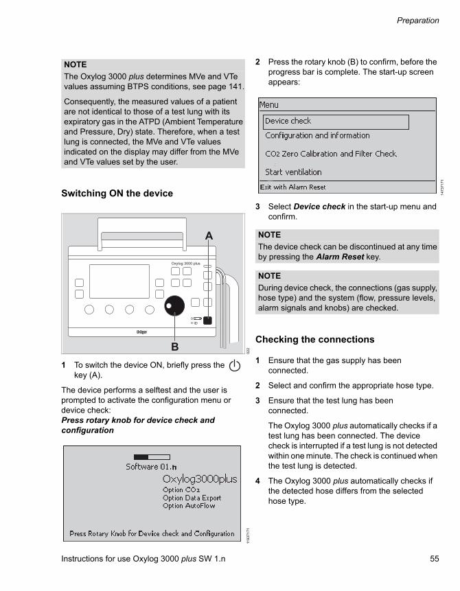
Switching ON the device
1 To switch the device ON, briefly press the key (A).
The device performs a selftest and the user is prompted to activate the configuration menu or device check:Press rotary knob for device check and configuration
2 Press the rotary knob (B) to confirm, before the progress bar is complete. The start-up screen appears:
3 Select Device check in the start-up menu and confirm.
Checking the connections
1 Ensure that the gas supply has been connected.
2 Select and confirm the appropriate hose type.
3 Ensure that the test lung has been connected.
The Oxylog 3000 plus automatically checks if a test lung has been connected. The device check is interrupted if a test lung is not detected within one minute. The check is continued when the test lung is detected.
4 The Oxylog 3000 plus automatically checks if the detected hose differs from the selected hose type.
NOTE
The Oxylog 3000 plus determines MVe and VTe values assuming BTPS conditions, see page 141.
Consequently, the measured values of a patient are not identical to those of a test lung with its expiratory gas in the ATPD (Ambient Temperature and Pressure, Dry) state. Therefore, when a test lung is connected, the MVe and VTe values indicated on the display may differ from the MVe and VTe values set by the user.
02
211
93
71
71
Oxylog 3000 plus
A
B
14
73
71
71
NOTE
The device check can be discontinued at any time by pressing the Alarm Reset key.
NOTE
During device check, the connections (gas supply, hose type) and the system (flow, pressure levels, alarm signals and knobs) are checked.

Preparation
56 Instructions for use Oxylog 3000 plus SW 1.n
If the wrong hose type is selected:
– Press the Alarm Reset key to cancel the device check.
– Restart the device check.
– Select the correct hose type.
System check
5 Set the control knobs (A) below the display to the required values.
The Oxylog 3000 plus successively activates the audible and optical alarm signals and prompts the user to acknowledge each signal.
6 Confirm the audible and optical alarm signals. The device check continues automatically.
During the automatic test sequence, the Oxylog 3000 plus checks the flow, pressure levels and alarm signals. Corresponding sounds are heard.
The progress bar shows the progress made by the check.
The result is displayed on the last page of the device check screens. If all tests are completed successfully, the device will go to the last page. If a test fails, the device will go directly after the failed test to the last page, without performing the other tests.
After confirmation, the system returns to the menu screen.
If the service inspection date has been passed without servicing, the text Service date overdue ! will appear in the window after finishing the device check. In this case the device must be serviced immediately.
High airway pressure and disconnection alarm check
Checking the alarm in case of high airway pressure:
1 Ventilate the test lung in CMV mode.
2 Press the test lung manually, until the airway pressure exceeds the set Pmax.
3 Check if the PAw high alarm occurs.
Checking the alarm in case of breathing circuit disconnection:
1 Ventilate the test lung in CMV mode.
2 Disconnect the breathing hose and/or flow measuring lines from the ventilator.
3 Check if an applicable alarm occurs.
02
3Oxylog 3000 plus
A

Instructions for use Oxylog 3000 plus SW 1.n 57
Preparation
Checking the power supply failure alarm
A monthly check of the power supply failure alarm is recommended.
1 Switch the device on.
2 Disconnect the external power supply.
3 Remove the battery to activate the acoustic alarm signal.
4 Listen for the acoustic alarm signal.
5 When the power supply failure alarm check is completed, re-insert the battery in the battery compartment of the Oxylog 3000 plus.
6 Connect the external power supply.
Problem solving
If the device check is not completed successfully:
1 Refer to "Error messages during the device check" on page 120 of the "Problem solving" section.
2 Call DrägerService.
NOTE
If no alarm is heard, call DrägerService.
WARNING
The ventilator is ready for operation only after all functional tests have been successfully performed.
Preparation
58 Instructions for use Oxylog 3000 plus SW 1.n
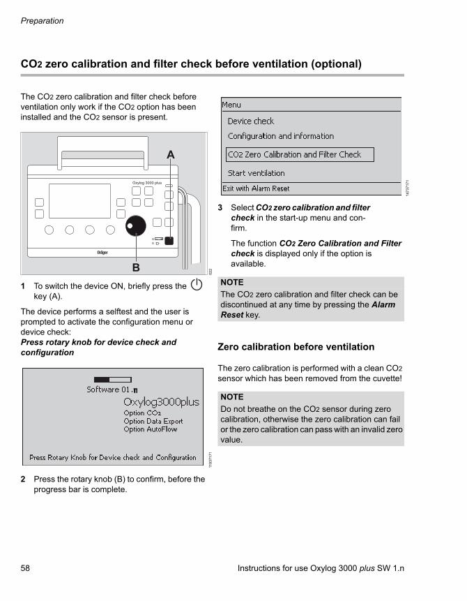
CO2 zero calibration and filter check before ventilation (optional)
The CO2 zero calibration and filter check before ventilation only work if the CO2 option has been installed and the CO2 sensor is present.
1 To switch the device ON, briefly press the key (A).
The device performs a selftest and the user is prompted to activate the configuration menu or device check:Press rotary knob for device check and configuration
2 Press the rotary knob (B) to confirm, before the progress bar is complete.
3 Select CO2 zero calibration and filter check in the start-up menu and con-firm.
The function CO2 Zero Calibration and Filter check is displayed only if the option is available.
Zero calibration before ventilation
The zero calibration is performed with a clean CO2 sensor which has been removed from the cuvette!
02
211
93
71
71
Oxylog 3000 plus
A
B
14
73
71
71
NOTE
The CO2 zero calibration and filter check can be discontinued at any time by pressing the Alarm Reset key.
NOTE
Do not breathe on the CO2 sensor during zero calibration, otherwise the zero calibration can fail or the zero calibration can pass with an invalid zero value.

Instructions for use Oxylog 3000 plus SW 1.n 59
Preparation
1 Remove the CO2 sensor (A) from the cuvette (B).
2 Select and activate Zero calibration. The screen displays the text Remove the sensor from cuvette then press rotary knob.
3 Confirm. The zero calibration starts and the line displays Zero calibration in progress. After a successful zero calibration, the line briefly displays Zero calibration OK.
4 Press Alarm Reset to exit.
5 Reconnect the CO2 sensor to the cuvette.
If zero calibration was not successful:
The Oxylog 3000 plus displays the alarm message Zero calibration failed.
Redo the zero calibration.
If zero calibration is still not possible:
1 Check whether the sensor (A) is soiled and clean it if necessary. If the sensor is defective, replace the sensor.
2 Redo the zero calibration.
CO2 filter check before ventilation
1 Remove the CO2 sensor (A) from the cuvette (B).
2 Connect the CO2 sensor (A) to the test filter (B).
3 Select Filter check.
4 Confirm. The filter check starts and the screen displays Filter check in progress. After a successful filter check, the line briefly displays Filter check OK.
5 Press Alarm Reset to exit.
6 Reconnect the CO2 sensor to the cuvette.
If the check was not successful:
The Oxylog 3000 plus displays the alarm Filter check failed. The measured CO2 value is outside the permissible tolerance range.
Check whether the sensor (A) or test filter (B) is soiled and clean them if necessary. Repeat the CO2 filter check.
17
91
48
37
17
1
AB
NOTE
Before the CO2 filter check can be performed, the CO2 zero calibration must be completed successfully. Otherwise the CO2 filter check may be outside of the tolerance range.
17
7
A
B

Preparation
60 Instructions for use Oxylog 3000 plus SW 1.n
If the check was still not successful:
Perform the CO2 gas check, see page 105.
For information on connecting the CO2 sensor and cuvette, see page 48. For information on CO2 zero calibration and filter testing during ventilation, see
page 91. For information on CO2 measurement see page 91. For information on CO2 configuration in Customer Service Mode, see page 103.
Preparation for use after system check, CO2 zero calibration and CO2 filter check
1 Assemble the Oxylog 3000 plus for operation. Refer to the "Assembly" on page 35.
2 Connect to the power supply and gas supply. Refer to "Internal rechargeable battery" on page 37 and "Connecting the gas supply" on page 41.
3 Start the ventilator:
Select Start ventilation from the menu and confirm.
Or
Press the Alarm Reset key.
14
73
71
71

Instructions for use Oxylog 3000 plus SW 1.n 61
Operation
Operation
Starting operation. . . . . . . . . . . . . . . . . . . . . 62
Switching ON the device . . . . . . . . . . . . . . . . 62
Preparing the ventilation mode . . . . . . . . . . 64
Activating the ventilation mode. . . . . . . . . . . . 64Setting ventilation parameters . . . . . . . . . . . . 64
VC-CMV, VC-AC . . . . . . . . . . . . . . . . . . . . . . 65
VC-CMV . . . . . . . . . . . . . . . . . . . . . . . . . . . . . 65VC-AC . . . . . . . . . . . . . . . . . . . . . . . . . . . . . . 66Activating AutoFlow (optional) . . . . . . . . . . . . 67Cardiopulmonary resuscitation (CPR) . . . . . . 67
VC-SIMV, VC-SIMV/PS . . . . . . . . . . . . . . . . . 68
VC-SIMV. . . . . . . . . . . . . . . . . . . . . . . . . . . . . 68VC-SIMV/PS. . . . . . . . . . . . . . . . . . . . . . . . . . 69Setting AutoFlow (optional) . . . . . . . . . . . . . . 69
PC-BIPAP, PC-BIPAP/PS . . . . . . . . . . . . . . . 70
PC-BIPAP. . . . . . . . . . . . . . . . . . . . . . . . . . . . 70PCBIPAP/PS . . . . . . . . . . . . . . . . . . . . . . . . . 71
Spn-CPAP, Spn-CPAP/PS . . . . . . . . . . . . . . . 72
SpnCPAP . . . . . . . . . . . . . . . . . . . . . . . . . . . . 72Apnea ventilation . . . . . . . . . . . . . . . . . . . . . . 73Spn-CPAP/PS. . . . . . . . . . . . . . . . . . . . . . . . . 74Cardio-pulmonary Resuscitation (CPR) . . . . . 74
Non-invasive ventilation (NIV). . . . . . . . . . . 75
Special functions . . . . . . . . . . . . . . . . . . . . . 76
Manual inspiration/Inspiration hold. . . . . . . . . 76100 % O2 (optional) . . . . . . . . . . . . . . . . . . . . 76O2 inhalation (optional). . . . . . . . . . . . . . . . . . 76
O2 concentration by "O2 blending" . . . . . . 78
Setting the HME correction . . . . . . . . . . . . . 79
Calibration. . . . . . . . . . . . . . . . . . . . . . . . . . . 80
Screen brightness . . . . . . . . . . . . . . . . . . . . 80
Alarm volume. . . . . . . . . . . . . . . . . . . . . . . . 80
Shutdown . . . . . . . . . . . . . . . . . . . . . . . . . . . 81

Operation
62 Instructions for use Oxylog 3000 plus SW 1.n
Starting operation
The actual screen display may differ in appearance or configuration.
Switching ON the device
To switch the device ON, briefly press the key (A).
The Oxylog 3000 plus performs a selftest. The selftest will be completed in approximately 6 seconds.
During the selftest the start-up screen is briefly displayed. It includes a progress bar indicating the progress of the selftest, the software version, the enabled software options, and the prompt to activate the device check by pressing the rotary knob (B).
If the rotary knob (B) is not pressed during the selftest, the hose selection page is displayed.
Select the connected hose type by turning the rotary knob (B) and confirm by pressing the rotary knob (B).
The ventilator now automatically begins ventilation with the default settings.
WARNING
Only use a ventilator that has been cleaned, disinfected and successfully tested to be ready for operation, to prevent a health risk for the patient and user.
Refer to the chapter "Cleaning, Disinfection and Sterilization" on page 121.
01
33
71
70
119
37
17
1
Oxylog 3000 plus
A
B
14
93
71
71
NOTE
As long as the hose selection page is shown, the patient is not being ventilated.
NOTE
The menu to select the hose type can be configured. Refer to the "Customer Service Mode" on page 97.
Instructions for use Oxylog 3000 plus SW 1.n 63
Operation
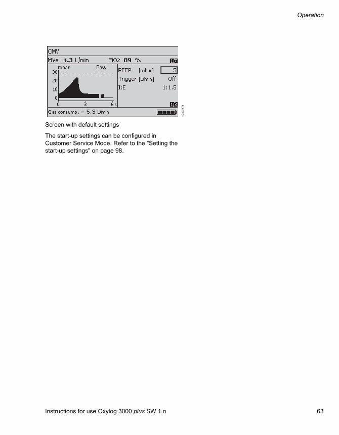
Screen with default settings
The start-up settings can be configured in Customer Service Mode. Refer to the "Setting the start-up settings" on page 98.
10
43
71
71
Operation
64 Instructions for use Oxylog 3000 plus SW 1.n
Preparing the ventilation mode
Activating the ventilation mode
Press and hold a ventilation mode key for approximately 3 seconds.
Or
Press a ventilation mode key and confirm by pressing the rotary knob.
The new ventilation mode selected is now effective.
For an overview of all ventilation modes, refer to "Range of functions" on page 22. For a detailed explanation on all ventilation modes, refer to "Description" on page 155.
Setting ventilation parameters
Adjust the relevant control knob below the display.
Or
Select, set and confirm a parameter on the display with the rotary knob.
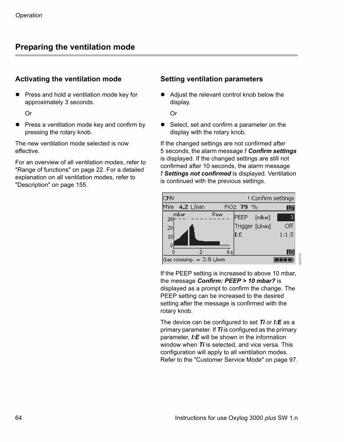
If the changed settings are not confirmed after 5 seconds, the alarm message ! Confirm settings is displayed. If the changed settings are still not confirmed after 10 seconds, the alarm message ! Settings not confirmed is displayed. Ventilation is continued with the previous settings.
If the PEEP setting is increased to above 10 mbar, the message Confirm: PEEP > 10 mbar? is displayed as a prompt to confirm the change. The PEEP setting can be increased to the desired setting after the message is confirmed with the rotary knob.
The device can be configured to set Ti or I:E as a primary parameter. If Ti is configured as the primary parameter, I:E will be shown in the information window when Ti is selected, and vice versa. This configuration will apply to all ventilation modes. Refer to the "Customer Service Mode" on page 97.
12
13
71
71

Instructions for use Oxylog 3000 plus SW 1.n 65
Operation
VC-CMV, VC-AC
VC-CMV
Volume Controlled - Controlled Mandatory Ventilation
Volume-controlled ventilation with a fixed mandatory minute volume MV set by the tidal volume VT and the respiratory rate RR. For patients who are not breathing spontaneously.
Set the ventilation pattern with the controls below the display:
– Tidal volume VT
– Respiratory rate RR(minimum possible respiratory rate: 5 /min)
– Maximum airway pressure Pmax
– O2 concentration FiO2
The following can be set on the display:
– Positive end-expiratory pressure PEEP
– Trigger sensitivity
– Ventilation time ratio I:E or inspiratory time Ti
When setting the respiratory rate RR, tidal volume VT or I:E/Ti, the associated values for inspiratory flow and Ti/I:E are automatically displayed in the information window.
– Plateau time Tplat as a percentage of the inspiratory time
– AutoFlow (optional)
02
5
Paw
Flow
Tinsp Te
Pplat
Plateau timeTplat
1RR
Insp. Flow
t
t
Pmax
PEEP
Exp. Flow
10
43
71
71
10
53
71
71

Operation
66 Instructions for use Oxylog 3000 plus SW 1.n
– Hose type
The selected hose type must match the hose type in use. Otherwise a correct volume measurement cannot be guaranteed.
– CO2 cuvette type (optional)
VC-AC
VC-AC – Volume Controlled – Assist Control
For synchronization with the patient's inspiratory efforts. For patients with partial spontaneous breathing.
The mandatory breaths are synchronized with the patient's spontaneous inspiratory efforts when the trigger is activated and the trigger sensitivity is set.
The actual respiratory rate may be higher than the set respiratory rate RR.
Successful patient triggering is briefly indicated by an asterisk (*) on the left side of the curve window.
Activating and setting the trigger
1 Press the Settings key (A) until the Trigger parameter is displayed.
2 Select the line Trigger on the display and then set and confirm the value with the rotary knob.Low value = high sensitivity.
The ventilation mode AC is shown on the display.
13
73
71
71
14
53
71
71
NOTE
The cuvette windows of the reusable cuvette and disposable cuvette have different optical properties. Therefore, the correct cuvette type must be selected in the settings menu. Otherwise the zero point will be shifted by as much as ±8 mmHg CO2.
NOTE
If a trigger value is set in ventilation mode VC-CMV, the ventilation modus changes to VC-AC.
00
53
71
70
Oxylog 3000 plus
A

Instructions for use Oxylog 3000 plus SW 1.n 67
Operation
Deactivating the trigger
1 Set a value less than 1 L/min or greater than 15 L/min (off is displayed instead of a value).
2 Press the rotary knob to confirm.
The last effective trigger value is adopted by the ventilator when changing from VC-AC to PC-BIPAP or SpnCPAP.
Activating AutoFlow (optional)
The AutoFlow-AF function can be set for VC-CMV and VC-AC.
When AutoFlow is switched on, the setting Tplat is no longer valid, and Slope must be set.
For more information on AutoFlow, refer to "AutoFlow" on page 160.
Cardiopulmonary resuscitation (CPR)
During cardiopulmonary resuscitation, the airway pressure Paw is increased because of chest compressions.
The Oxylog 3000 plus will try to limit the airway pressure Paw to the set Pmax, without ending the inspiration prematurely.
However, if due to compressions the airway pressure Paw exceeds the set Pmax by 5 mbar, the Oxylog 3000 plus cycles to the expiratory phase.
Therefore in general, if Pmax is set to a higher value, a higher minute volume is possible. However, this increases the intrathoracic pressure and may reduce coronary perfusion.
10
73
71
71
-1

Operation
68 Instructions for use Oxylog 3000 plus SW 1.n
VC-SIMV, VC-SIMV/PS
VC-SIMV
Volume Controlled - Synchronized Intermittent Mandatory Ventilation
For patients with inadequate spontaneous breathing, or for patients who are to be weaned gradually.
A fixed mandatory minute volume MV is set by the tidal volume VT and the respiratory rate RR. The patient can breathe spontaneously between the mandatory breaths and thus contribute to the total minute volume. Spontaneous breathing can be assisted with PS.
Set the ventilation pattern with the controls below the display:
– Tidal volume VT
– Respiratory rate RR(minimum possible respiratory rate: 2 /min).
– Maximum airway pressure Pmax
– O2 concentration FiO2
The following can be set on the display:
– Positive end-expiratory pressure PEEP
– Pressure Support Psupp above PEEP
– Trigger sensitivity
Successful patient triggering is indicated by an asterisk (*) on the left side of the curve window.
– Ventilation time ratio I:E or inspiratory time Ti
When setting the respiratory rate RR, tidal volume VT or Ti/I:E, the associated values for inspiratory flow and Ti/I:E are automatically displayed in the information window.
– Plateau time Tplat as a percentage of the inspiratory time
– AutoFlow (optional)
02
7Paw
Flow
Ti
Pmax
PEEP
shortrise time
longrise time
Pressuresupport PS
Trigger window
RR
Insp. Flow
t
t
1
10
73
71
71
-11
58
37
17
1-1
Microprocessor system
Pressure control V6
O2 F1
F2
DR
SV
S8
S4
S9 S7 S5 S6
NV
V10
V7 V8
S3
Gas blender
V1 - 3
P
P
E
P E P E P E P E
E
Human lung

Instructions for use Oxylog 3000 plus SW 1.n 69
Operation
– Insp.term.%PIFInspiration termination criteria of pressure supported strokes, as percentage of the peak inspiratory flow (PIF).
– Hose typeThe selected hose type must match the hose type in use. Otherwise a correct volume measurement cannot be guaranteed.
– CO2 cuvette type (optional)
VC-SIMV/PS
The following parameters can be adjusted on-screen in addition to the parameters of ventilation mode VC-SIMV:
– Setting on page 1: Pressure Support Psupp above PEEP
– Setting on page 2: Pressure rise time Slope (condition: Psupp > 0 mbar)
Flat slope = slow pressure rise
Medium slope = medium pressure rise
Steep slope = rapid pressure rise
Setting AutoFlow (optional)
The AutoFlow-AF function can be set for VC-SIMV and SIMV/PS.
When AutoFlow is switched on, the setting Tplat is no longer valid, and Slope must be set.
For more information on AutoFlow, refer to "AutoFlow" on page 160.
14
43
71
71
14
33
71
71
NOTE
The cuvette windows of the reusable cuvette and disposable cuvette have different optical properties. Therefore, the correct cuvette type must be selected in the settings menu. Otherwise the zero point will be shifted by as much as ±8 mmHg CO2.
14
23
71
71
-11
07
37
17
1-1

Operation
70 Instructions for use Oxylog 3000 plus SW 1.n
PC-BIPAP, PC-BIPAP/PS
PC-BIPAP
Pressure Controlled – Biphasic Positive Airway Pressure
Pressure-controlled ventilation combined with spontaneous breathing throughout the respiratory cycle and variable Pressure Support at CPAP level.
For patients without spontaneous breathing and spontaneously breathing patients until shortly before extubation. The patient is weaned by gradually reducing the mandatory portion of the total minute volume MV and by reducing the Pressure Support Psupp.
The mandatory portion of the total minute volume MV is set via the inspiratory pressure Pinsp, the positive endexspiratory pressure PEEP and the respiratory rate RR.
Refer to the description on page 159 for details.
Set the ventilation pattern with the controls below the display:
– Respiratory rate RR
– Maximum airway pressure Pmax
– O2 concentration FiO2
The following can be set on the display:
– Positive end-expiratory pressure PEEP
– Inspiratory pressure Pinsp
– Pressure Support Psupp above PEEP
– Trigger sensitivitySuccessful patient triggering is indicated by an asterisk (*) on the left side of the curve window.
– Ventilation time ratio I:E or inspiratory time Ti
– Pressure rise time Slope (effective for the PC-BIPAP stroke and Pressure Support Psupp)
– NIV – non-invasive ventilationRefer to "Non-invasive ventilation (NIV)" on page 75.
02
8
Paw
Flow
Pinsp
PEEP
Longrise time
Short rise time
t
tTi
Shortrise time
Longrise time
Pressure support PS
Trigger window
RR1
Without spontaneous breathing
With spontaneous breathing
10
83
71
71
14
13
71
71

Instructions for use Oxylog 3000 plus SW 1.n 71
Operation
– Insp.term.%PIFInspiration termination criteria of pressure supported strokes, as percentage of the peak inspiratory flow (PIF).
– Hose typeThe selected hose type must match the hose type in use. Otherwise a correct volume measurement cannot be guaranteed.
– CO2 cuvette type (optional)
PCBIPAP/PS
The following parameters can be adjusted on-screen in addition to the parameters of ventilation mode PC-BIPAP:
– Setting on page 1: Pressure Support Psupp above PEEP
– Setting on page 2: Pressure rise time Slope
Flat slope = slow pressure rise
Medium slope = medium pressure rise
Steep slope = rapid pressure rise
14
03
71
71
15
03
71
71
NOTE
The cuvette windows of the reusable cuvette and disposable cuvette have different optical properties. Therefore, the correct cuvette type must be selected in the settings menu. Otherwise the zero point will be shifted by as much as ±8 mmHg CO2.
12
43
71
71

Operation
72 Instructions for use Oxylog 3000 plus SW 1.n
Spn-CPAP, Spn-CPAP/PS
SpnCPAP
Spontaneous Continuous Positive Airway Pressure
For patients with sufficient spontaneous breathing.
If Pressure Support (PS) is not active, the patient's spontaneous breathing is supported only by an increased PEEP.
Set the ventilation pattern with the controls below the display:
– Maximum airway pressure Pmax
– O2 concentration FiO2
The following can be set on the display:
– Positive end-expiratory pressure PEEP
– Pressure Support Psupp above PEEP
– NIV– non-invasive ventilation Refer to "Non-invasive ventilation (NIV)" on page 75.
– Insp.term.%PIFInspiration termination criteria of pressure supported strokes, as percentage of the peak inspiratory flow (PIF).
– Hose typeThe selected hose type must match the hose type in use. Otherwise a correct volume measurement cannot be guaranteed.
– CO2 cuvette type (optional)
15
73
71
71
15
13
71
71
15
23
71
71
NOTE
The cuvette windows of the reusable cuvette and disposable cuvette have different optical properties. Therefore, the correct cuvette type must be selected in the settings menu. Otherwise the zero point will be shifted by as much as ±8 mmHg CO2.

Instructions for use Oxylog 3000 plus SW 1.n 73
Operation
Apnea ventilation
Apnea ventilation is only applicable when using the Spn-CPAP mode. In the event of an apnea, the ventilator will automatically activate volume-controlled mandatory ventilation (VC-CMV).
When an apnea occurs, the device issues an alarm signal and, when the alarm time Tapn has been reached, starts volume-controlled ventilation with the parameters respiratory rate RRapn, tidal volume VTapn, and the maximum airway pressure Pmax. The ventilation time ratio I:E = 1:1.5 and the plateau time Tplat = 0 are preset during apnea ventilation.
Setting apnea ventilation
1 Set Tapn with the rotary knob (B) to a value between 15 and 60 seconds.
The parameters RRapn and VTapn required for setting apnea ventilation are displayed.
2 Set RRapn and VTapn.
3 Set Pmax to set the maximum permissible airway pressure during apnea ventilation.
02
9U
S
Paw
Flow
Apnea alarm timeTapn
Startapnea ventilationwith apnea alarm
t
t
1RRapn
Pmax
06
83
71
70
scre
en
13
Oxylog 3000 plus
A B

Operation
74 Instructions for use Oxylog 3000 plus SW 1.n
Ending apnea ventilation
Press the Alarm Reset key.
The ventilator is again ventilating with the previous settings in ventilation mode Spn-CPAP.
Deactivating apnea ventilation
Set Tapn to OFF.
Spn-CPAP/PS
If Psupp is set to a value above 0 mbar, the following parameters can be adjusted on-screen in addition to those for Spn-CPAP:
– Trigger sensitivitySuccessful patient triggering is indicated by an asterisk (*) on the left side of the curve window.
– Pressure rise time Slope (effective for Pressure Support Psupp)
Cardio-pulmonary Resuscitation (CPR)
Refer to the "Cardiopulmonary resuscitation (CPR)" on page 67.
NOTE
Apnea ventilation can only be activated in ventilation mode Spn-CPAP without NIV.
The minimum minute volume required by the patient must be monitored via the lower alarm limit MVe .
12
53
71
71

Instructions for use Oxylog 3000 plus SW 1.n 75
Operation
Non-invasive ventilation (NIV)
Use of NIV
NIV can only be activated as a supplementary function in the ventilation modes Spn-CPAP (/PS), PC-BIPAP (/PS), VC-CMV / AF, VC-AC / AF and VC-SIMV / AF. The Oxylog 3000 plus automatically adjusts to the requirements of non-invasive ventilation. Mask leakages are detected by the device and compensated for. Therefore, the displayed measured values VTe and MVe include the leakage. The leakage alarm is inactive.
To switch on NIV
1 Select NIV off.
2 Select NIV on and confirm.
– The suffix NIV appears in the ventilation mode field.
WARNING
If NIV is not active, leakage during ventilation will corrupt the VTe and MVe measured values.
WARNING
Risk of undetected leakage and inadequate ventilation
Ensure that NIV is not activated for intubated patients.
WARNING
Risk of CO2 rebreathing
Bacterial filters, HMEs and masks increase the resistance and dead space volume of the breathing circuit. Note the manufacturer’s directions.
WARNING
Check MVe alarm limits after deactivating NIV mode.
WARNING
Risk of aspiration
Avoid high airway pressure.
12
83
71
71
WARNING
Risk of inadequate ventilation
The minimum minute volume required by the patient must be monitored via the lower alarm limit MVe .
NOTE
Apnea ventilation is not possible when NIV is active.

Operation
76 Instructions for use Oxylog 3000 plus SW 1.n
Special functions
Manual inspiration/Inspiration hold
The Manual inspiration/Inspiration hold function will either initiate a new manual breath or extend the inspiratory phase of the current breath by up to 15 seconds.
The pattern of the manually started breath corresponds with the set ventilation mode.
This function is not available for:
– Spn-CPAP without PS
– O2 inhalation (optional)
Activating Manual inspiration/Inspiration hold
Press the Insp. Hold (A) key for the desired inspiratory time.
100 % O2 (optional)
To apply 100 % O2 for 3 minutes regardless of the momentarily set value.
Briefly press key 100 % O2 (B). Its indicator lights up for 3 minutes.
After the 3 minutes, or when the 100 % O2 key is pressed again, the ventilator continues ventilation with the current set O2 value. The indicator dims.
O2 inhalation (optional)
If a tracheal stenosis or other obstruction occurs, the flow is interrupted by the ventilator for 5 seconds at an airway pressure of 30 mbar and the airway pressure is reduced to 0 mbar. The !!! Paw high alarm is active.
01
23
71
70
Oxylog 3000 plus
A
B
WARNING
The O2 inhalation function is not a ventilation mode.
It may only be used for patients with spontaneous breathing who receive a constant O2 flow of between 0 and 15 L/min via a mask.
NOTE
The options 100 % O2 and O2 inhalation are mutually exclusive.

Instructions for use Oxylog 3000 plus SW 1.n 77
Operation
Activating O2 inhalation
1 Connect the inhalation mask via the hose to the device (B).
2 Press and hold key O2 inhalation (A) for approx. 3 seconds.
O2 inhalation is performed with the previously effective setting.
3 Set and confirm the required O2 flow via the rotary knob (C).
Display (example):
08
33
71
70
07
13
71
70
Oxylog 3000 plus
C
A B

Operation
78 Instructions for use Oxylog 3000 plus SW 1.n
O2 concentration by "O2 blending"
The FiO2 can be set between 40 % and 100 % O2 independently of the ventilation mode. To generate the set inspiratory O2 concentration, ambient air is drawn in using the injector principle.
However, the O2 concentration which can be realized depends on the mean airway pressure and the inspiratory flow. The O2 concentration can never be lower than 40 %.
This is shown in the following schematic illustrations:
O2 concentration at a mean airway pressure of 5 mbar
O2 concentration at a mean airway pressure of 15 mbar
O2 concentration at a mean airway pressure of 30 mbar
O2 concentration at a mean airway pressure of 60 mbar
The O2 concentration is a calculated value. It is not measured by an internal O2 sensor.
If the Oxylog 3000 plus is unable to reach the set O2 concentration, the user is prompted to correct the setting by the message Check settings: FiO2.
Correct setting by control FiO2.
When the O2 concentration has been set, the value will be displayed after approximately 30 seconds.
When patients are breathing spontaneously, the achievable O2 concentration will depend on the profile of the inspiratory flow.
03
10
32
O2 (%)
Flow(L/min.)
O2 = f(Flow, Paw)
40
200 3 40
80 (%)
100
Flow(L/min.)
O2 = f(Flow, Paw)
40
200 10 35
82 (%)
100
O2 (%)
03
30
34
Flow(L/min.)
O2 = f(Flow, Paw)
40
200 15 30
85 (%)
100
O2 (%)
Flow(L/min.)
O2 = f(Flow, Paw)
40
200 20
93 (%)
100
O2 (%)

Instructions for use Oxylog 3000 plus SW 1.n 79
Operation
Setting the HME correction
The temperature and moisture influence of the HME (heat and moisture exchanger) have an effect on the flow measurement. The Oxylog 3000 plus can compensate for the presence of an HME.
When using HME, select, set and confirm HME – On in the Settings window with the rotary knob.
When HME – ON is selected, the flow sensor expects an expiratory gas temperature of 35 °C and a relative humidity of 0 %.
When HME – Off is selected, the flow sensor expects an expiratory gas temperature of 37 °C and a relative humidity of 100 %.
13
83
71
71

Operation
80 Instructions for use Oxylog 3000 plus SW 1.n
Calibration
The pressure and flow sensors are automatically calibrated by the device at regular intervals without interrupting ventilation.
The saved calibration values are retained even when the device is switched OFF.
The CO2 sensor must be calibrated manually if the required CO2 value is not reached during the CO2 gas check.
For information on calibration of the CO2 sensor, refer to "Customer Service Mode" on page 97.
Screen brightness
The screen brightness level can be set on the last page of the settings menu, from level 1/4 to 4/4.
During battery operation, when no controls have been set for a period longer than one minute, the screen will automatically be dimmed (power save mode).
The screen brightness level in power save mode can be adjusted in Customer Service Mode. Refer to the "Customer Service Mode" on page 97.
Alarm volume
The alarm volume can be set on the last page of the alarm menu, from level 1/4 to 4/4.

Instructions for use Oxylog 3000 plus SW 1.n 81
Operation
Shutdown
After disconnecting the patient, switch off the ventilator.
1 To switch the device OFF, hold down the key (A) for approximately 3 seconds.
Ventilation is now stopped and a high-priority alarm is issued.This alarm can be silenced with the key.
2 Either:
Press the rotary knob (B) to confirm switch off.
Or
Press the key (A) to resume ventilation with the previous settings.
3 With gas supply from an O2 cylinder:Close the cylinder valve.
With gas supply from the pipeline gas supply system:Disconnect the high-pressure connection from the source.
4 Disconnect the breathing hose.
00
33
71
70
NOTE
When the device is switched OFF, the battery is still being charged if the device is connected to an external power source.
Oxylog 3000 plus
AB
WARNING
The cylinder valve must be closed completely to avoid gas flow leakage by the device.
04
8
CAUTION
When disconnecting the breathing hose from the device, always grip the sleeve (A) and never the corrugations (B).
If this is not done, the corrugations or hose may be torn from the sleeve.
A
B

82 Instructions for use Oxylog 3000 plus SW 1.n
This page has been left blank intentionally.

Instructions for use Oxylog 3000 plus SW 1.n 83
Alarms
Alarms
Safety information . . . . . . . . . . . . . . . . . . . . 84
Position of user relative to alarm system . . . . 84
Alarm priorities . . . . . . . . . . . . . . . . . . . . . . . 84
Alarm indication . . . . . . . . . . . . . . . . . . . . . . 85
Setting alarm limits . . . . . . . . . . . . . . . . . . . 87

Alarms
84 Instructions for use Oxylog 3000 plus SW 1.n
Safety information
Position of user relative to alarm system
The alarm system is designed so that the user can see the alarm messages from a distance of 1 m (39 in).
The specified alarm tone volumes apply to a distance of 1 m (39 in) at normal ambient sound volume.
Alarm priorities
The actual screen display may differ in appearance or configuration.
The Oxylog 3000 plus assigns priorities to alarms. The alarm message is highlighted with the corresponding number of exclamation marks. Also, different acoustic alarm signals are generated for the various alarm priorities.!!! = Warning!! = Caution! = Note
For information on how to remedy alarm causes, refer to the table "Alarm – Cause – Remedy" on page 110.
Warning
An alarm of high priority The alarm indicator (B) flashes red.
WARNING
Risk when failing to hear alarms
The alarm volume must be adapted to the surroundings (see page 80), and the user must stay within hearing range of the acoustic alarm signal.
This allows for rapid detection of the alarm and appropriate response.
WARNING
Pay special attention in environments where the surrounding noise interferes with hearing the maximum alarm volume of the device (e.g. in a helicopter).
03
6
Oxylog 3000 plus
C
B
A

Instructions for use Oxylog 3000 plus SW 1.n 85
Alarms
Warnings are preceded by three exclamation marks and displayed in inverted form (C).
Example:
The Oxylog 3000 plus generates a 5-tone acoustic alarm signal that is repeated twice about every 7 seconds.
Caution
An alarm of medium priority The alarm indicator (A) flashes yellow.Caution messages are preceded by two exclamation marks.
Example: !! No int. battery?
The Oxylog 3000 plus generates a 3-tone acoustic alarm signal that is repeated about every 20 seconds.
Advisory
An alarm of low priority The yellow alarm indicator (A) lights up.Advisory messages are preceded by one exclamation mark.
Example:! Settings not confirmed
The Oxylog 3000 plus generates a 2-tone acoustic alarm signal that sounds only once.
Alarm indication
In case of an alarm, the following visual and acoustic alarm signals are generated:
– The indicator (A) flashes red or yellow, or lights up yellow.
– The alarm message appears on the upper right corner of the screen (C). In addition, alarm tones are issued.
When the cause of an alarm has been remedied, the acoustic alarm signal stops. The alarm message remains on-screen, however, until the user acknowledged the message with the Alarm Reset key or the message is overwritten by a new alarm.
Press the Alarm Reset key (B).The alarm message is no longer displayed.
!!! Apnea ventilation
03
7
Oxylog 3000 plus
C B
A
NOTE
Oxylog 3000 plus has no distributed alarm system. Data transfer via the data port using the MEDIBUS.X protocol is no substitute for regular checking of the monitoring on the device's display.

Alarms
86 Instructions for use Oxylog 3000 plus SW 1.n
Silencing acoustic alarm signals
Press the key (A).The alarm indicator remains active and all current acoustic alarm signals are silenced for about 2 minutes. Alarms with a higher priority override the alarm tone suppression, meaning they are indicated by an acoustic signal.All alarm tones are resumed by the device after these 2 minutes.
To cancel the silencing before the 2 minutes elapse:
Press the key (A) again.
In case of power supply failure
In the event of a power supply failure, ventilation, volume measurement and alarms do not operate. An acoustic alarm signal sounds to indicate the power supply failure.
Spontaneous breathing can continue through the emergency air inlet.
Immediately start ventilating the patient with an independent manual ventilation device (breathing bag) and maintain ventilation as necessary using PEEP and/or increased inspiratory oxygen concentration.
WARNING
Risk of alarms being unnoticed
Check the display regularly for alarm messages when the acoustic alarm signals are silenced.
03
8
NOTE
To be notified of new acoustic alarm signals, the 2 minutes alarm silencing must be reset.
Oxylog 3000 plus
A
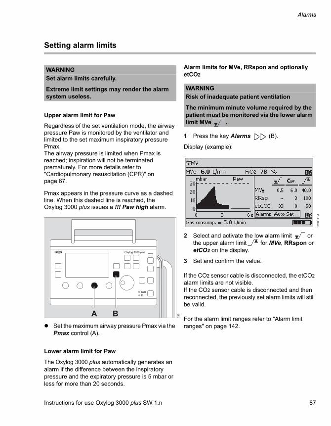
Instructions for use Oxylog 3000 plus SW 1.n 87
Alarms
Setting alarm limits
Upper alarm limit for Paw
Regardless of the set ventilation mode, the airway pressure Paw is monitored by the ventilator and limited to the set maximum inspiratory pressure Pmax.The airway pressure is limited when Pmax is reached; inspiration will not be terminated prematurely. For more details refer to "Cardiopulmonary resuscitation (CPR)" on page 67.
Pmax appears in the pressure curve as a dashed line. When this dashed line is reached, the Oxylog 3000 plus issues a !!! Paw high alarm.
Set the maximum airway pressure Pmax via the Pmax control (A).
Lower alarm limit for Paw
The Oxylog 3000 plus automatically generates an alarm if the difference between the inspiratory pressure and the expiratory pressure is 5 mbar or less for more than 20 seconds.
Alarm limits for MVe, RRspon and optionally etCO2
1 Press the key Alarms (B).
Display (example):
2 Select and activate the low alarm limit or the upper alarm limit for MVe, RRspon or etCO2 on the display.
3 Set and confirm the value.
If the CO2 sensor cable is disconnected, the etCO2 alarm limits are not visible. If the CO2 sensor cable is disconnected and then reconnected, the previously set alarm limits will still be valid.
For the alarm limit ranges refer to "Alarm limit ranges" on page 142.
WARNING
Set alarm limits carefully.
Extreme limit settings may render the alarm system useless.
03
9
Oxylog 3000 plus
A B
WARNING
Risk of inadequate patient ventilation
The minimum minute volume required by the patient must be monitored via the lower alarm limit MVe .
110
37
17
1-2

Alarms
88 Instructions for use Oxylog 3000 plus SW 1.n
Setting alarm limits automatically
The function Alarms: Autoset sets the alarm limits on the basis of the actual measured values at the time of activation. This automatic setting of alarm limits is performed only once, when confirmed with the rotary knob.
1 Press the key Alarms (B).
2 Select and activate the line Alarms: Autoset on the display.
3 Press the rotary knob to confirm Alarms: Autoset or press the Alarm Reset key to leave the settings unchanged.
The auto alarm limits are based on the actual measured values as follows:
The etCO2 / auto alarm limits are based on the actual etCO2 value as follows:
WARNING
Risk of hypoventilation
After using the function Alarms: Autoset, check if the new alarm limits are appropriate for the patient.
Alarm Setting
MVe Measured value –20 % with a minimum of 0.5 L/min. At less than 0.5 L/min the limit remains unchanged.
MVe Measured value +30 % or +2 L/min, whichever is smaller.
RRsp Measured value +5/min with a minimum of 10/min.
etCO2 Based on the current value
Lower alarm limit [mmHg]
Current measured value [mmHg]
Upper alarm limit [mmHg]
Unchanged <15 Unchanged
Measured value –5
15 to 35 Measured value +15
Measured value –7
35 to 45 Measured value +10
Measured value –10
>45 Measured value +5
Lower alarm limit [kPa] or [Vol%]
Current measured value [kPa] or [Vol%]
Upper alarm limit [kPa] or [Vol%]
Unchanged <2.0 Unchanged
Measured value –0.7
2.0 to 4.7 Measured value +2.0
Measured value –0.9
4.7 to 6.0 Measured value +1.3
Measured value –1.3
>6.0 Measured value +0.7

Instructions for use Oxylog 3000 plus SW 1.n 89
Monitoring
Monitoring
Displaying curves. . . . . . . . . . . . . . . . . . . . . 90
Displaying measured values . . . . . . . . . . . . 90
CO2 measurement (optional). . . . . . . . . . . . 91
Selecting the cuvette type . . . . . . . . . . . . . . . 91Checking the CO2 sensor during ventilation. . 91Performing zero calibration during ventilation 92Checking the CO2 filter during ventilation. . . . 93
Data communication (optional) . . . . . . . . . . 94
Connecting an external device . . . . . . . . . . . . 94Serial port . . . . . . . . . . . . . . . . . . . . . . . . . . . . 94Requirements for the electrical properties of connected devices and networks . . . . . . . . . . 94

Monitoring
90 Instructions for use Oxylog 3000 plus SW 1.n
Displaying curves
The curve window can display the airway pressure curve Paw, the flow curve or the CO2 curve (optional). Refer to the "On-screen window structure" on page 32.
To display a different curve:
Press the Curves key.
Displaying measured values
Measured values are displayed in the measured values window.
To switch between the values:
Press the Values key: the next value pair is displayed on the screen.
The following values can be displayed:
– MVe
– FiO2
– f
– VTe
– PEEP
– Pmean
– PIP
– Pplat
– MVespon
– RRspon
– etCO2
When the CO2 sensor is connected to the ventilator, the etCO2 value will be shown automatically in the measured values window.
The values are shown in pairs; the pairs of values can be configured as required. Refer to the "Customer Service Mode" on page 97.
CurvesCurves

Instructions for use Oxylog 3000 plus SW 1.n 91
Monitoring
CO2 measurement (optional)
CO2 measurement only works when the CO2 option has been installed and the CO2 sensor is connected.
1 Connect the CO2 sensor and the cuvette (refer to "Connecting the CO2 sensor and the cuvette" on page 48).
2 Select the cuvette type in the settings menu (refer to "Selecting the cuvette type").
The following will be activated:
– Curve window: CO2 curve
– Measured values window: the parameter etCO2 will automatically be displayed.
– Alarm window: etCO2 high and etCO2 low alarms
For more information on curves and measured values: refer to "Enlarged view of CO2 curve" on page 34.
For more information on configuring measured value pairs: refer to "Customer Service Mode" on page 97.
For connecting the CO2 sensor and cuvette, see page 48. For information on CO2 zero calibration and filter testing before ventilation, see page 58. For information on CO2 configuration in Customer Service Mode, see page 103.
Selecting the cuvette type
To select the cuvette type (reusable or disposable):
1 Press the Settings key.
2 Select and activate the line Cuvette type.
3 Select the cuvette type and confirm.
Checking the CO2 sensor during ventilation
The following checks of the CO2 sensor are recommended:
NOTE
The cuvette windows of the reusable cuvette and disposable cuvette have different optical properties. Therefore, the correct cuvette type must be selected in the settings menu. Otherwise the zero point will be shifted by as much as ±8 mmHg CO2.
NOTE
If a wrong cuvette type is selected, the Oxylog 3000 plus displays the alarm !!! Check cuvette type.
Check Interval
CO2 zero calibra-tion
Weekly
CO2 filter check Monthly
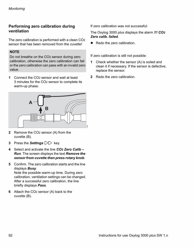
Monitoring
92 Instructions for use Oxylog 3000 plus SW 1.n
Performing zero calibration during ventilation
The zero calibration is performed with a clean CO2 sensor that has been removed from the cuvette!
1 Connect the CO2 sensor and wait at least 3 minutes for the CO2 sensor to complete its warm-up phase.
2 Remove the CO2 sensor (A) from the cuvette (B).
3 Press the Settings key.
4 Select and activate the line CO2 Zero Calib – Run. The screen displays the text Remove the sensor from cuvette then press rotary knob.
5 Confirm. The zero calibration starts and the line displays Busy. Note the possible warm-up time. During zero calibration, ventilation settings can be changed.After a successful zero calibration, the line briefly displays Pass.
6 Attach the CO2 sensor (A) back to the cuvette (B).
If zero calibration was not successful:
The Oxylog 3000 plus displays the alarm !!! CO2 Zero calib. failed.
Redo the zero calibration.
If zero calibration is still not possible:
1 Check whether the sensor (A) is soiled and clean it if necessary. If the sensor is defective, replace the sensor.
2 Redo the zero calibration.
NOTE
Do not breathe on the CO2 sensor during zero calibration, otherwise the zero calibration can fail or the zero calibration can pass with an invalid zero value.
17
9
AB

Instructions for use Oxylog 3000 plus SW 1.n 93
Monitoring
Checking the CO2 filter during ventilation
1 Remove the CO2 sensor from the cuvette.
2 Connect the CO2 sensor (A) to the test filter (B).
3 Press the Settings key.
4 Select and activate the line CO2 Filter check – Run.
5 Confirm. The filter check starts and the line displays Busy. During the filter check, ventilation settings can be changed.After a successful filter check, the line briefly displays Pass.
6 Attach the CO2 sensor (A) back to the cuvette.
If the check was not successful:
The Oxylog 3000 plus displays the alarm !!! CO2 Filter check failed. The measured CO2 value is outside the permissible tolerance range.
Check whether the sensor (A) or test filter (B) is soiled and clean them if necessary. Repeat the CO2 filter check.
If the check is again not successful:
Perform the CO2 gas check, see page 105.
NOTE
Before the CO2 filter check can be performed, the CO2 zero calibration must be completed successfully. Otherwise the CO2 filter check may be outside of the tolerance range.
17
7
A
B

Monitoring
94 Instructions for use Oxylog 3000 plus SW 1.n
Data communication (optional)
With the data communication option, measured values, curves, alarms, and settings can be transferred using the MEDIBUS.X-protocol.
MEDIBUS.X is a software protocol for the transfer of data between the Oxylog 3000 plus and an external medical or non-medical device (e.g., patient monitors or computers for data management systems).
The combination of the Oxylog 3000 plus and an external device must comply with IEC/EN 60601-1 and IEC/EN 60601-1-2.
For more information, refer to "MEDIBUS.X, Rules and Standards for Implementation" (90 52 607) and "MEDIBUS.X, Profile Definition for Data Communication V1.n" (90 52 608).
Connecting an external device
1 Connect the external device to the data communication cable 57 05 301.
2 Connect the data communication cable to the Oxylog 3000 plus.
Serial port
The port for the data communication cable corresponds to an RS232 interface according to EIA RS-232 (CCITT V.24/V.28)
Requirements for the electrical properties of connected devices and networks
The serial port is only suitable for connecting devices or networks which have a maximum nominal voltage of 24 VDC on the network end and which comply with one of the following standards:
– IEC 60950-1: Ungrounded SELV circuits
– IEC 60601-1 (from 2nd edition): Touchable secondary circuits
Connections to IT networks
Connecting this device to a network that incorporates other devices or making subsequent changes to that network can lead to new risks for patients, users, and third parties. Before the device is connected to the network or the network is changed, these risks must be identified, analyzed and evaluated by the hospital's IT officer according to the standard IEC 80001-1 (Risk management for IT networks with medical devices). On the basis of the results, appropriate measures have to be taken.
Examples of subsequent changes to the network:
– Changing the network configuration
– Removing devices from the network
– Adding new devices to the network
– Performing upgrades or updates on devices that are connected to the network
WARNING
Risk due to incorrectly transmitted data
All data sent to other devices via the MEDIBUS.X interface of the device may be displayed incorrectly or incompletely. They are therefore only for information purposes.
Do not use data displayed on other devices for diagnostic or therapeutic decisions.
Do not use data displayed on other devices for patient or device monitoring.
Instructions for use Oxylog 3000 plus SW 1.n 95
Configuration
Configuration
Displaying configuration and information . 96
Language . . . . . . . . . . . . . . . . . . . . . . . . . . . . 96Battery type . . . . . . . . . . . . . . . . . . . . . . . . . . 96
Customer Service Mode. . . . . . . . . . . . . . . . 97
Setting the start-up settings . . . . . . . . . . . . . . 98Configuring the start-up settings for the breathing hose and cuvette . . . . . . . . . . . . . . 100Setting the date and time . . . . . . . . . . . . . . . . 100Configuring the measured values windows . . 100Activating options . . . . . . . . . . . . . . . . . . . . . . 101Checking keys and control knobs. . . . . . . . . . 101Checking the loudspeaker, buzzer, LEDs and display . . . . . . . . . . . . . . . . . . . . . . . . . . . . . . 101Displaying power supply data. . . . . . . . . . . . . 102Checking the safety valve. . . . . . . . . . . . . . . . 102Displaying the technical logbook . . . . . . . . . . 102Displaying the user logbook . . . . . . . . . . . . . . 103Displaying contact details for maintenance and service . . . . . . . . . . . . . . . . . . . . . . . . . . . 103Checking and calibrating the CO2 sensor . . . 103Setting the minimum alarm volume . . . . . . . . 107Setting the alarm tone type. . . . . . . . . . . . . . . 107Exiting Customer Service Mode . . . . . . . . . . . 107
Customer service manual . . . . . . . . . . . . . . 108

Configuration
96 Instructions for use Oxylog 3000 plus SW 1.n
Displaying configuration and information
The actual screen display may differ in appearance or configuration.
1 To switch the device ON briefly press the key. The device performs a selftest and the user is prompted to activate the configuration menu or device check:Press rotary knob for device check and configuration.
2 Press the rotary knob to confirm, before the progress bar is complete.The start-up menu is then displayed:
3 Select Configuration and Information and confirm.
The settings made in the Configuration window are retained after the ventilator is switched OFF.
Configuration can be canceled by pressing the Alarm reset key.
The following data can be displayed in the Configuration and Information windows:
– Language
– Identification No. (Device ID)
– Total hours of operation (Working hours)
– Hours of operation since the last inspection and maintenance (Hours since service time)
– Battery type and battery capacity.
Language
1 Press the key Settings to select the menu Configuration.
2 Select and activate the line Language.
3 Select the language and confirm.The new language selected is effective immediately.
Battery type
Press the key Settings to select the menu Information.The performance data of the inserted battery are displayed on the device.
15
33
71
71
06
63
71
71
scre
en
17

Instructions for use Oxylog 3000 plus SW 1.n 97
Configuration
Customer Service Mode
In Customer Service Mode, the ventilator performs function tests, outputs status information and permits configuration of parameter settings.The display language in Customer Service Mode is English. It cannot be changed.
NOTE
Ventilation is not possible when the device is in Customer Service Mode.
NOTE
The following screens are only intended for maintenance personnel and qualified specialists, and are protected against unauthorized adjustment.
For more information regarding access, see page 173.
001 Set startup settings. Configure start-up settings, restore manufacturer's default settings.
002 Hose/cuvette start-up settings. Select which breathing circuit and CO2 cuvette type to use.
003 Set date and time. Set date and time.
004 Set measured values display window. Configure the layout of measured values in the measured values window or restore manufacturer's default settings.
005 Enter activation code. Enter the activation code for options.
006 Test buttons and potentiometer. Check for correct functioning of keys and controls.
007 Test loudspeaker, buzzer, LEDs and display.
Check for correct functioning of loudspeaker, buzzer, LEDs and display.
008 Display battery and supply data. Display of battery data and state of charge.
009 Check safety valve. Checking of the safety valve.
010 Display info logbook. Calibration logbook and technical errors in chronological sequence.
011 Display user logbook. Logbook of operating phases, ventilator settings and alarms.
012 Display maintenance and service contact information.
Display the maintenance schedule and contact informa-tion for maintenance personnel.
013 CO2 sensor. Check or calibrate the CO2 sensor.
019 Acoustic alarm configuration Set the minimum alarm volume and alarm tone type.
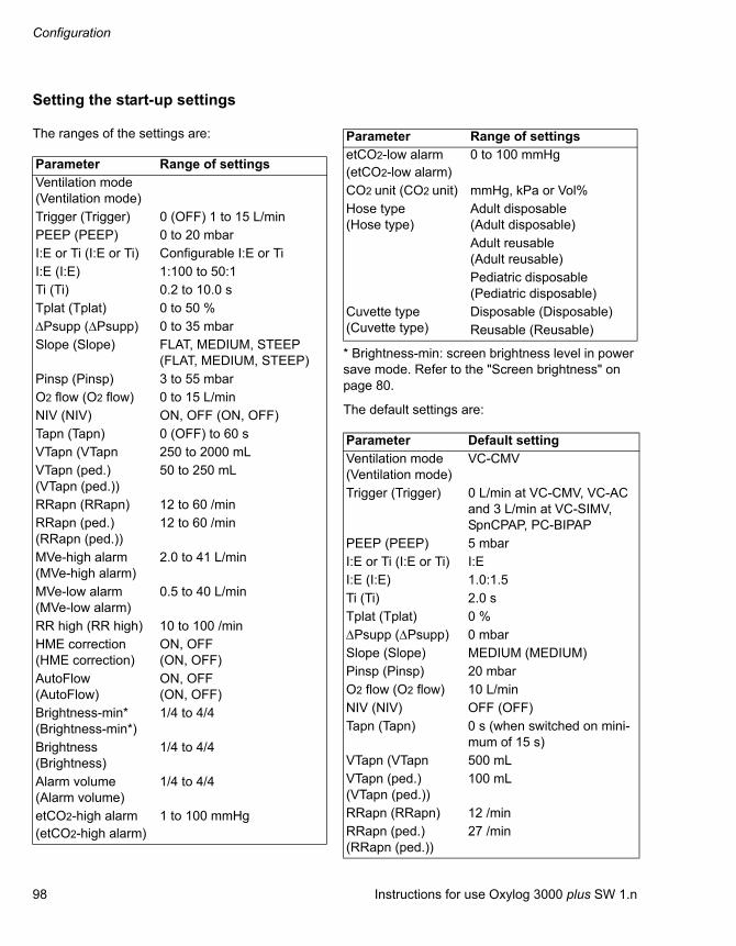
Configuration
98 Instructions for use Oxylog 3000 plus SW 1.n
Setting the start-up settings
The ranges of the settings are:
* Brightness-min: screen brightness level in power save mode. Refer to the "Screen brightness" on page 80.
The default settings are:
Parameter Range of settingsVentilation mode (Ventilation mode)Trigger (Trigger) 0 (OFF) 1 to 15 L/minPEEP (PEEP) 0 to 20 mbarI:E or Ti (I:E or Ti) Configurable I:E or TiI:E (I:E) 1:100 to 50:1Ti (Ti) 0.2 to 10.0 sTplat (Tplat) 0 to 50 %Psupp (Psupp) 0 to 35 mbarSlope (Slope) FLAT, MEDIUM, STEEP
(FLAT, MEDIUM, STEEP)Pinsp (Pinsp) 3 to 55 mbarO2 flow (O2 flow) 0 to 15 L/minNIV (NIV) ON, OFF (ON, OFF)Tapn (Tapn) 0 (OFF) to 60 sVTapn (VTapn 250 to 2000 mLVTapn (ped.) (VTapn (ped.))
50 to 250 mL
RRapn (RRapn) 12 to 60 /minRRapn (ped.) (RRapn (ped.))
12 to 60 /min
MVe-high alarm (MVe-high alarm)
2.0 to 41 L/min
MVe-low alarm (MVe-low alarm)
0.5 to 40 L/min
RR high (RR high) 10 to 100 /minHME correction(HME correction)
ON, OFF(ON, OFF)
AutoFlow (AutoFlow)
ON, OFF(ON, OFF)
Brightness-min* (Brightness-min*)
1/4 to 4/4
Brightness (Brightness)
1/4 to 4/4
Alarm volume(Alarm volume)
1/4 to 4/4
etCO2-high alarm(etCO2-high alarm)
1 to 100 mmHg
etCO2-low alarm(etCO2-low alarm)
0 to 100 mmHg
CO2 unit (CO2 unit) mmHg, kPa or Vol%Hose type (Hose type)
Adult disposable(Adult disposable)Adult reusable(Adult reusable)Pediatric disposable(Pediatric disposable)
Cuvette type(Cuvette type)
Disposable (Disposable)Reusable (Reusable)
Parameter Default settingVentilation mode (Ventilation mode)
VC-CMV
Trigger (Trigger) 0 L/min at VC-CMV, VC-AC and 3 L/min at VC-SIMV, SpnCPAP, PC-BIPAP
PEEP (PEEP) 5 mbarI:E or Ti (I:E or Ti) I:EI:E (I:E) 1.0:1.5Ti (Ti) 2.0 sTplat (Tplat) 0 %Psupp (Psupp) 0 mbarSlope (Slope) MEDIUM (MEDIUM)Pinsp (Pinsp) 20 mbarO2 flow (O2 flow) 10 L/minNIV (NIV) OFF (OFF)Tapn (Tapn) 0 s (when switched on mini-
mum of 15 s)VTapn (VTapn 500 mLVTapn (ped.) (VTapn (ped.))
100 mL
RRapn (RRapn) 12 /minRRapn (ped.) (RRapn (ped.))
27 /min
Parameter Range of settings
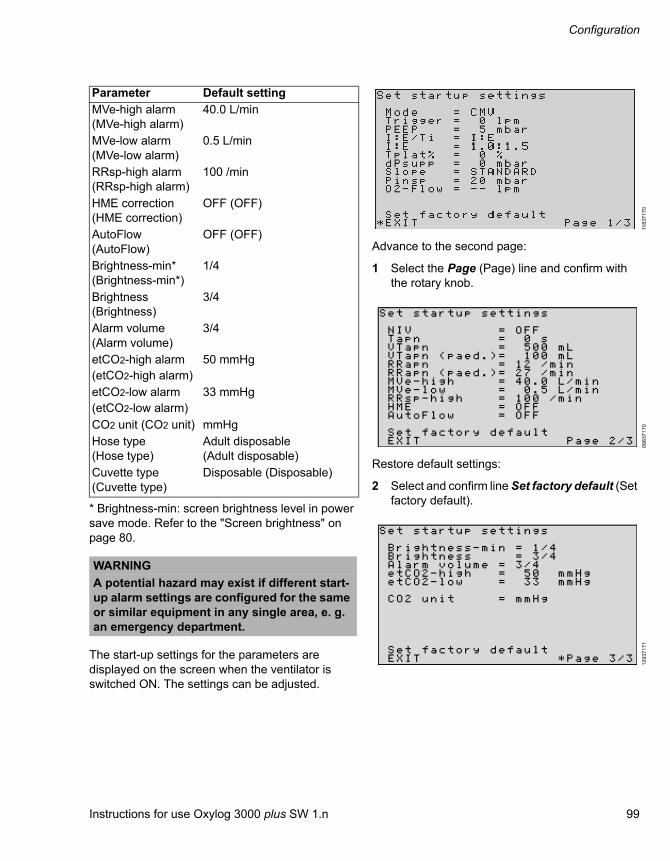
Instructions for use Oxylog 3000 plus SW 1.n 99
Configuration
* Brightness-min: screen brightness level in power save mode. Refer to the "Screen brightness" on page 80.
The start-up settings for the parameters are displayed on the screen when the ventilator is switched ON. The settings can be adjusted.
Advance to the second page:
1 Select the Page (Page) line and confirm with the rotary knob.
Restore default settings:
2 Select and confirm line Set factory default (Set factory default).
MVe-high alarm (MVe-high alarm)
40.0 L/min
MVe-low alarm (MVe-low alarm)
0.5 L/min
RRsp-high alarm(RRsp-high alarm)
100 /min
HME correction(HME correction)
OFF (OFF)
AutoFlow (AutoFlow)
OFF (OFF)
Brightness-min* (Brightness-min*)
1/4
Brightness (Brightness)
3/4
Alarm volume(Alarm volume)
3/4
etCO2-high alarm(etCO2-high alarm)
50 mmHg
etCO2-low alarm(etCO2-low alarm)
33 mmHg
CO2 unit (CO2 unit) mmHgHose type (Hose type)
Adult disposable (Adult disposable)
Cuvette type(Cuvette type)
Disposable (Disposable)
WARNING
A potential hazard may exist if different start-up alarm settings are configured for the same or similar equipment in any single area, e. g. an emergency department.
Parameter Default setting
118
37
17
00
98
37
17
01
29
37
17
1

Configuration
100 Instructions for use Oxylog 3000 plus SW 1.n
Configuring the start-up settings for the breathing hose and cuvette
– Ask for hose type = Yes (Ask for hose type = Yes): When switching on the device, prior to ventilation, the user is first prompted to select the hose type.
– Ask for hose type = No (Ask for hose type = No): When switching on the device, it directly starts ventilating after the selftest, with the start-up settings for the breathing hose type.
– Hose type (Hose type): Current start-up setting for the breathing hose (Adult Reusable, Adult Disposable or Pediatric Disposable).
– Cuvette type (optional) (Cuvette type (optional)): Current start-up setting for the CO2 cuvette type (Reusable or Disposable).
Setting the date and time
The date and time can be set.
1 Set the current date and time with the positions Year, Month, Day, Hour and Minute (Year, Month, Day, Hour and Minute) and confirm.
2 Confirm date and time with Set (Set).
Configuring the measured values windows
In the measured values window, 6 pairs of different values can be displayed. On the 7th page of the Settings window, an overview of all measured values will be displayed.
The arrangement of measured value pairs on the individual pages of the measured values window can be varied. etCO2 is optional.
Each measured value can be freely selected in any position and is only displayed at that position.
To define the 11 values displayed:
Start configuration on page 1/6 and continue through to 6/6.
115
37
17
01
02
37
17
0
116
37
17
0
NOTE
It is advisable to display the FiO2 value during ventilation.

Instructions for use Oxylog 3000 plus SW 1.n 101
Configuration
Activating options
The activation codes for options can be entered. The activated options are then displayed.For the possible options, refer to "List of accessories" on page 165.
Checking keys and control knobs
The operating elements on the front panel are displayed schematically on the screen.
– Display = screen
– B = buttons
To test the control knobs, set the following values:
– VT to 500 mL
– RR to 20/min
– Pmax to 40 mbar
– FiO2 to 40 %
These settings are displayed on the screen.
To test the buttons:
1 Briefly press the corresponding button.The associated letter on the screen changes from "B" to "X". If the button has an indicator, it will be illuminated by the device. If there are buttons without an indicator, the yellow warning indicator will light up on the device.
The function of the rotary knob is not included in the test.
Checking the loudspeaker, buzzer, LEDs and display
To test the loudspeaker, buzzer, all LEDs and the display:
1 Select the required test.
2 Confirm the selection by pressing the rotary knob. The requested function is tested by the device.
To test the screen display (Test display).
3 Turn the rotary knob; various test cards are displayed.
The selected test remains active until the rotary knob is pressed again.
114
37
17
00
94
37
17
0
NOTE
If you press the key for longer than 3 seconds, the ventilator switches OFF.
09
53
71
70

Configuration
102 Instructions for use Oxylog 3000 plus SW 1.n
Displaying power supply data
The parameters of the rechargeable battery and the status of the external power supply are displayed.Display (example):
Advance to the second page:
Select line Page (Page), confirm and turn the rotary knob.
Display (example):
Checking the safety valve
For safety inspection, a flow can be generated to test the safety valve.
Displaying the technical logbook
Any technical errors and/or special occurrences, such as activation of a software option, completion of the device check and device calibration, are listed in chronological sequence.
The entries in the logbook cannot be deleted and are retained when the device is switched on and off or after a power supply failure.
A maximum of 570 logbook entries can be displayed on the screen. When the capacity of the logbook is reached, the oldest entries are overwritten.
Display (example):
09
63
71
70
33
3
15
93
71
71
06
63
71
71

Instructions for use Oxylog 3000 plus SW 1.n 103
Configuration
To advance to the next page:
Select line Page (Page), confirm and turn the rotary knob.
Displaying the user logbook
The operational phases (including switching the device off and on) with the device settings and the time are listed in chronological order.
The entries in the logbook cannot be deleted and are retained when the device is switched on and off or after a power supply failure.
A maximum of 935 logbook entries can be displayed on the screen. When the capacity of the logbook is reached, the oldest entries are overwritten. For alarms, only the occurrence of the alarm condition is recorded.
To advance to the next page:
Select line Page (Page), confirm and turn the rotary knob.
Displaying contact details for maintenance and service
The maintenance schedule and contact details for maintenance personnel are displayed. The message Service date overdue ! (Service date overdue !) is shown if service is needed.
Checking and calibrating the CO2 sensor
Prerequisite: The CO2 option is activated. The following actions can be selected:
– Zero Calibration (Zero Calibration);
– Filter/gas check (Filter/gas check);
– Filter check (Filter check);
– Gas check (Gas check);
– Gas Calibration (Gas Calibration);
– Start gas calibration (Start gas calibration);
– Reset to factory defaults (Reset to factory defaults)
112
37
17
0
10
13
71
70
117
37
17
1

Configuration
104 Instructions for use Oxylog 3000 plus SW 1.n
Performing zero calibration
1 Connect the CO2 sensor to the ventilator. Wait at least 3 minutes for the CO2 sensor to complete its warm-up phase.
2 Remove the CO2 sensor (A) from the cuvette (B).
3 Open page CO2 sensor (CO2 sensor), select the line Zero calibration (Zero calibration) and confirm. The screen displays the text Remove sensor from cuvette (Remove sensor from cuvette).
4 Confirm with the rotary knob. The Oxylog 3000 plus performs the zero calibration and displays the message Zero calibration in progress (Zero calibration in progress).
If zero calibration was successful:
After approx. 5 seconds the Oxylog 3000 plus confirms with the message Zero calibration successful (Zero calibration successful).
If zero calibration was not successful:
The Oxylog 3000 plus displays the alarm message Zero calibration failed (Zero calibration failed).
Redo the zero calibration.
If zero calibration is still not possible:
1 Check whether the sensor (A) is soiled and clean it if necessary. If the sensor is defective, replace the sensor.
2 Redo the zero calibration.
Performing the CO2 filter check
1 Open page CO2 sensor (CO2 sensor), select the line Filter/gas check (Filter/gas check) and then the line Filter check (Filter check) and confirm. The screen displays the text: Place sensor on test filter (Place sensor on test filter).
2 Remove the CO2 sensor from the cuvette and attach the CO2 sensor (A) to the test filter (B) of the sensor cable.
3 Confirm with the rotary knob. The Oxylog 3000 plus performs the filter check and displays the message Filter check in progress (Filter check in progress).
If the check was successful:
The Oxylog 3000 plus displays the message Filter check successful (Filter check successful). The measured CO2 value is within the permissible tolerance range.
If the check was not successful:
NOTE
Do not breathe on the CO2 sensor during zero calibration, otherwise the zero calibration can fail or the zero calibration can pass with an invalid zero value.
17
9
AB
NOTE
Before the CO2 filter check can be performed, the CO2 zero calibration must be completed successfully. Otherwise the CO2 filter check may be outside of the tolerance range.
17
7
A
B

Instructions for use Oxylog 3000 plus SW 1.n 105
Configuration
The Oxylog 3000 plus displays the alarm message Filter check failed (Filter check failed). The measured CO2 value is outside the permissible tolerance range.
Check whether the sensor (A) or test filter (B) is soiled and clean them if necessary. Repeat the CO2 filter check.
If the check was still not successful:
Perform the CO2 gas check.
Performing the CO2 gas check
Perform the CO2 gas check if the required CO2 value is not reached during the CO2 filter check.
1 Use the reusable cuvette from the calibration set.
2 Connect the test gas cylinder (A) and the cuvette (B) of the calibration set to the hose (C).
3 Fit the CO2 sensor (D) on the cuvette (B) of the calibration set and connect the CO2 sensor to the ventilator.
4 Open the page CO2 sensor (CO2 sensor), select the line Filter/gas check (Filter/gas check) and then the line Gas check (Gas check) and confirm. The display now shows Turn on test gas (Turn on test gas).
5 Read the CO2 concentration of the test gas from the test gas cylinder (A).
6 Open the test gas cylinder (E) and set the test gas flow to 0.1 L/min. Select CONTINUE (CONTINUE) and confirm with the rotary knob.
7 The Oxylog 3000 plus displays the CO2 concentration Measured CO2 value (Measured CO2 value).
8 About 1 minute after setting the test gas flow, check if the displayed CO2 value matches the CO2 concentration specified on the test gas cylinder (tolerance: ±0.2 Vol%).
9 Close the test gas cylinder.
If the measured CO2 value is outside the permitted tolerance, the CO2 sensor must be recalibrated with test gas.
CO2 calibration with test gas
The CO2 sensor must be calibrated if the required CO2 value is not reached during the CO2 gas check.
NOTE
Before the CO2 gas check can be performed, the CO2 zero calibration must be completed successfully. Otherwise the CO2 gas check may be outside of the tolerance range.
NOTE
For the CO2 gas check use only a test gas composed of CO2 and N2.
Otherwise values other than ±0.5 Vol% CO2 may be displayed.
17
6
B
C
E
A
D
NOTE
Before the CO2 calibration with test gas can be performed, the CO2 zero calibration must be completed successfully. Otherwise the CO2 calibration with test gas may be outside of the tolerance range.
NOTE
For the calibration use only a test gas composed of CO2 and N2.
Otherwise values other than ±0.5 Vol% CO2 may be displayed.
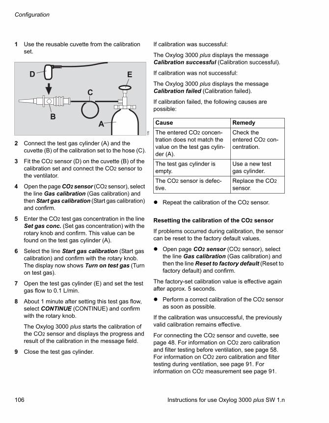
Configuration
106 Instructions for use Oxylog 3000 plus SW 1.n
1 Use the reusable cuvette from the calibration set.
2 Connect the test gas cylinder (A) and the cuvette (B) of the calibration set to the hose (C).
3 Fit the CO2 sensor (D) on the cuvette (B) of the calibration set and connect the CO2 sensor to the ventilator.
4 Open the page CO2 sensor (CO2 sensor), select the line Gas calibration (Gas calibration) and then Start gas calibration (Start gas calibration) and confirm.
5 Enter the CO2 test gas concentration in the line Set gas conc. (Set gas concentration) with the rotary knob and confirm. This value can be found on the test gas cylinder (A).
6 Select the line Start gas calibration (Start gas calibration) and confirm with the rotary knob. The display now shows Turn on test gas (Turn on test gas).
7 Open the test gas cylinder (E) and set the test gas flow to 0.1 L/min.
8 About 1 minute after setting this test gas flow, select CONTINUE (CONTINUE) and confirm with the rotary knob.
The Oxylog 3000 plus starts the calibration of the CO2 sensor and displays the progress and result of the calibration in the message field.
9 Close the test gas cylinder.
If calibration was successful:
The Oxylog 3000 plus displays the message Calibration successful (Calibration successful).
If calibration was not successful:
The Oxylog 3000 plus displays the message Calibration failed (Calibration failed).
If calibration failed, the following causes are possible:
Repeat the calibration of the CO2 sensor.
Resetting the calibration of the CO2 sensor
If problems occurred during calibration, the sensor can be reset to the factory default values.
Open page CO2 sensor (CO2 sensor), select the line Gas calibration (Gas calibration) and then the line Reset to factory default (Reset to factory default) and confirm.
The factory-set calibration value is effective again after approx. 5 seconds.
Perform a correct calibration of the CO2 sensor as soon as possible.
If the calibration was unsuccessful, the previously valid calibration remains effective.
For connecting the CO2 sensor and cuvette, see page 48. For information on CO2 zero calibration and filter testing before ventilation, see page 58. For information on CO2 zero calibration and filter testing during ventilation, see page 91. For information on CO2 measurement see page 91.
17
6
B
C
E
A
D
Cause Remedy
The entered CO2 concen-tration does not match the value on the test gas cylin-der (A).
Check the entered CO2 con-centration.
The test gas cylinder is empty.
Use a new test gas cylinder.
The CO2 sensor is defec-tive.
Replace the CO2 sensor.

Instructions for use Oxylog 3000 plus SW 1.n 107
Configuration
Setting the minimum alarm volume
1 Select the Minimum Level (Minimum Level) line and confirm.
2 Select the minimum alarm volume by turning the rotary knob and confirm.
Setting the alarm tone type
1 Select the Alarm sequence (Alarm sequence) line and confirm.
2 Select the alarm tone type DRAEGER or IEC by turning the rotary knob and confirm.
Exiting Customer Service Mode
1 Press the key for approximately 3 seconds; the indicator flashes yellow.
To turn ventilation on:
2 Briefly press the key .
Procedure to switch off the device:3 Press the rotary knob.
NOTE
The user cannot set an alarm volume below the set minimum alarm volume.
NOTE
The user cannot change the preset alarm tone type.

Configuration
108 Instructions for use Oxylog 3000 plus SW 1.n
Customer service manual
For further information on the Oxylog 3000 plus, refer to the Service Manual (can be ordered through DrägerService).
Instructions for use Oxylog 3000 plus SW 1.n 109
Problem solving
Problem solving
Alarm – Cause – Remedy. . . . . . . . . . . . . . . 110
Messages in the alarm message field . . . . 110
Additional messages in the alarm message field . . . . . . . . . . . . . . . . . . . . . . . . 117
Messages in the information field. . . . . . . . 118
Error messages during the device check . 120

Problem solving
110 Instructions for use Oxylog 3000 plus SW 1.n
Alarm – Cause – Remedy
The Oxylog 3000 plus prioritizes alarms and identifies them accordingly by means of exclamation marks:
In the following table, the alarm messages are listed in alphabetical order. If an alarm occurs, the table helps to identify causes and remedies. The different causes and remedies should be worked through in the order listed until the cause of the alarm has been resolved.
When multiple alarms occur, they are displayed according to their alarm rank, as illustrated in the table below. A lower number has a higher rank.
Messages in the alarm message field
!!! Warning High-priority alarm message
!! Caution Medium-priority alarm mes-sage
! Note Low-priority alarm message
Alarm Cause Remedy Rank
!!! Apnea Spontaneous breathing by the patient has failed, or disconnec-tion.
Check patient condition.
Ventilate in VC-CMV mode.
Ensure that hose connections are tight.
9
Faulty flow sensor. Replace the flow sensor.
!!! Apnea ventilation (only for CPAP)
The ventilator has automatically switched over to mandatory ven-tilation after detecting an apnea (only in Spn-CPAP mode).
Check patient condition.
Check ventilation settings To return to the original ventilation mode: Press the Alarm Reset key.
8
!! Charge int. battery
The Oxylog 3000 plus draws its power from the internal battery due to the absence of an external power supply. There are only approximately 10 minutes of operating time remaining in the internal battery.
The ventilator must immediately be reconnected to the mains power supply or an onboard power supply, or a fully charged battery must be installed (venti-lation stops while installing the battery).
33

Instructions for use Oxylog 3000 plus SW 1.n 111
Problem solving
!!! Check cuvette type
An incorrect CO2 cuvette type is selected.
Select correct cuvette type. 22
Cuvette or sensor soiled. Clean cuvette or sensor, or replace cuvette.
Zero point of the CO2 sensor is outside the tolerance range.
Perform the zero calibration.
Inspiratory CO2 concentration high.
Check patient status and venti-lation.
!!! Check meas-uring lines
The flow measuring lines are connected incorrectly.
Connect the flow measuring lines correctly.
10
! Check set-tings FiO2
The set FiO2 concentration can-not be achieved with the set flow.
Adjust inspiratory flow or FiO2 concentration (in accordance with measured value).
44
!! Check set-tings: flow
The flow resulting from the set-tings for tidal volume VT relative to Ti or I:E is not achievable (specified range 4 to 100 L/min).
Change tidal volume VT or inspiratory time Ti or ventilation time ratioI:E, plateau time Tplat, or respiratory rate RR.
30
!! Check set-tings: time
The inspiratory and / or expira-tory time resulting from the set-tings for RR and I:E or Ti are not possible.
Change RR or I:E or Ti. 29
!! Clean the CO2 cuvette
The sensor or cuvette window is soiled.
Clean sensor and cuvette window or replace cuvette.
21
Perform the zero calibration.
!! CO2 Filter check failed
The sensor reports a filter check failure.
Perform the zero calibration. 24
Do not breathe on the CO2 sen-sor during the filter check.
Clean CO2 test filter or CO2 sensor.
Perform the CO2 gas check.
!! CO2 sensor? The connector of the CO2 sensor was removed during operation.
Reinsert the connector. 20
The CO2 sensor has a hardware failure.
Replace the CO2 sensor.
Alarm Cause Remedy Rank

Problem solving
112 Instructions for use Oxylog 3000 plus SW 1.n
!! CO2 Zero calib. failed
Zero calibration of the CO2 sensor failed.
Redo the zero calibration. 23
Do not breathe on the CO2 sen-sor during zero calibration.
The sensor window is soiled. Clean the CO2 sensor window.
The CO2 sensor has a hardware failure.
Replace the CO2 sensor.
!!! CO2 Zero calib. request
Zero point of the CO2 sensor is outside the tolerance range.
Perform the zero calibration. 25
! Confirm settings
Changed setting has not been confirmed with the rotary knob.
Confirm the change of setting by pressing the rotary knob.
45
!!! Continuous high pressure
Breathing valve or breathing cir-cuit obstructed.
Check patient condition.
Check breathing valve and breathing circuit.
5
Increased expiratory resistance. Check bacterial/HME filter. Replace it if necessary.
Technical defect. Disconnect the patient from the device and continue ventilation without delay using another ventilator. Call DrägerService.
!! Control knob faulty (FiO2)
Technical defect. Ventilation is continued with last settings.Check patient condition and ventilation.Contact DrägerService.
19
!! Control knob faulty (Pmax)
Technical defect. Ventilation is continued with last settings.Check patient condition and ventilation.Contact DrägerService.
17
!! Control knob faulty (RR)
Technical defect. Ventilation is continued with last settings.Check patient condition and ventilation.Contact DrägerService.
16
!! Control knob faulty (VT)
Technical defect. Ventilation is continued with last settings.Check patient condition and ventilation.Contact DrägerService.
18
Alarm Cause Remedy Rank

Instructions for use Oxylog 3000 plus SW 1.n 113
Problem solving
!!! Device failure Technical defect. Disconnect the patient from the device and continue ventilation without delay using another ventilator.After pressing Alarm Reset the device will directly display fur-ther failure information in the "Customer Service Mode" menu. Call DrägerService.
1
!!! Display inop Technical defect. Disconnect the patient from the device and continue ventilation without delay using another ventilator. Call DrägerService.
40
!! etCO2 high The upper alarm limit for endtidal CO2 concentration has been exceeded.
Check patient condition. 26
Check alarm limits.
Adjust the alarm limit, if necessary.
!! etCO2 low The lower alarm limit for endtidal CO2 concentration has been exceeded.
Check patient condition. 27
Check alarm limits.
Adjust the alarm limit, if necessary.
!! Flow meas-urement inop
Measurement lines for flow measurement kinked, discon-nected or leaking.
Ensure flow measuring lines are connected correctly.
39
Faulty flow sensor. Replace the flow sensor.
Technical defect. Disconnect the device from the patient and continue ventilation without delay using another ventilator. Call DrägerService.
!! High respira-tory rate
Patient breathes at a high spontaneous rate.
Check patient condition, check ventilation pattern, correct alarm limit RRsp if necessary.
31
!! Int. battery charging inop
The internal battery is not being charged due to a battery failure.
Change internal battery. Call DrägerService.
34
The internal battery is not being charged due to a device malfunc-tion.
Continuous ventilation with this device is only possible with an external power source. Call DrägerService.
Alarm Cause Remedy Rank
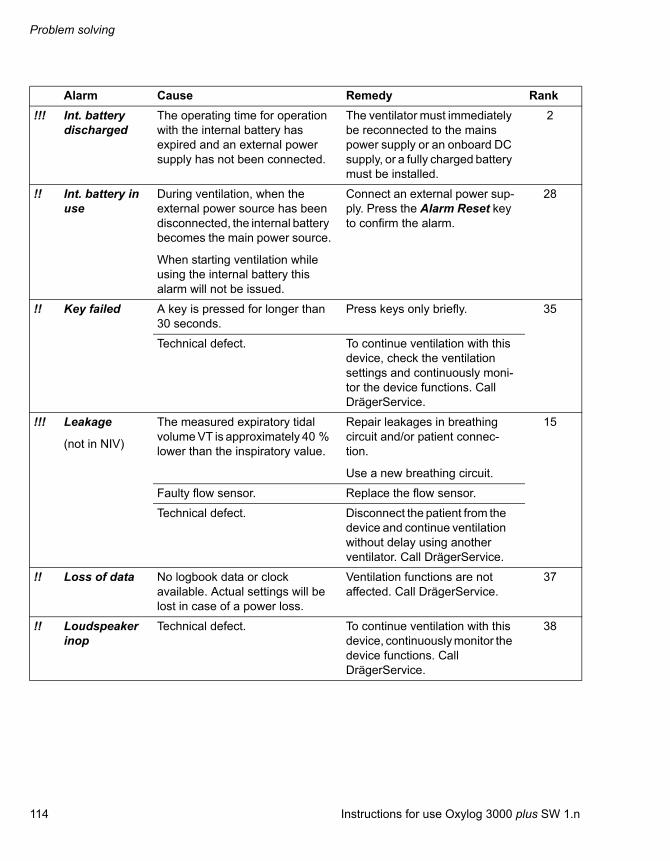
Problem solving
114 Instructions for use Oxylog 3000 plus SW 1.n
!!! Int. battery discharged
The operating time for operation with the internal battery has expired and an external power supply has not been connected.
The ventilator must immediately be reconnected to the mains power supply or an onboard DC supply, or a fully charged battery must be installed.
2
!! Int. battery in use
During ventilation, when the external power source has been disconnected, the internal battery becomes the main power source.
When starting ventilation while using the internal battery this alarm will not be issued.
Connect an external power sup-ply. Press the Alarm Reset key to confirm the alarm.
28
!! Key failed A key is pressed for longer than 30 seconds.
Press keys only briefly. 35
Technical defect. To continue ventilation with this device, check the ventilation settings and continuously moni-tor the device functions. Call DrägerService.
!!! Leakage
(not in NIV)
The measured expiratory tidal volume VT is approximately 40 % lower than the inspiratory value.
Repair leakages in breathing circuit and/or patient connec-tion.
Use a new breathing circuit.
15
Faulty flow sensor. Replace the flow sensor.
Technical defect. Disconnect the patient from the device and continue ventilation without delay using another ventilator. Call DrägerService.
!! Loss of data No logbook data or clock available. Actual settings will be lost in case of a power loss.
Ventilation functions are not affected. Call DrägerService.
37
!! Loudspeaker inop
Technical defect. To continue ventilation with this device, continuously monitor the device functions. Call DrägerService.
38
Alarm Cause Remedy Rank
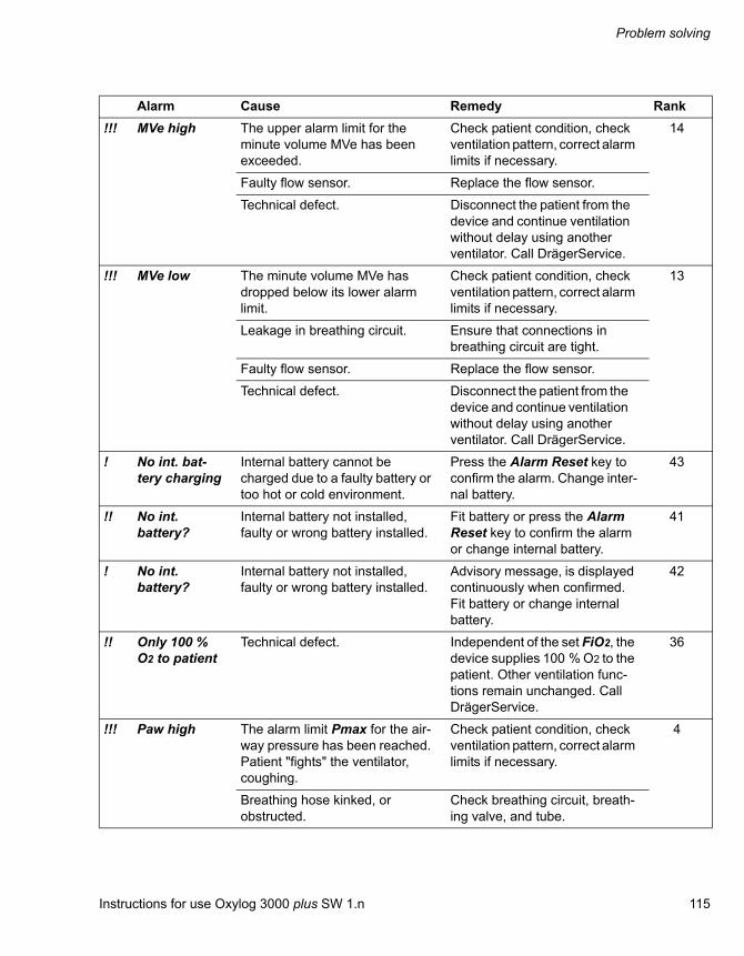
Instructions for use Oxylog 3000 plus SW 1.n 115
Problem solving
!!! MVe high The upper alarm limit for the minute volume MVe has been exceeded.
Check patient condition, check ventilation pattern, correct alarm limits if necessary.
14
Faulty flow sensor. Replace the flow sensor.
Technical defect. Disconnect the patient from the device and continue ventilation without delay using another ventilator. Call DrägerService.
!!! MVe low The minute volume MVe has dropped below its lower alarm limit.
Check patient condition, check ventilation pattern, correct alarm limits if necessary.
13
Leakage in breathing circuit. Ensure that connections in breathing circuit are tight.
Faulty flow sensor. Replace the flow sensor.
Technical defect. Disconnect the patient from the device and continue ventilation without delay using another ventilator. Call DrägerService.
! No int. bat-tery charging
Internal battery cannot be charged due to a faulty battery or too hot or cold environment.
Press the Alarm Reset key to confirm the alarm. Change inter-nal battery.
43
!! No int. battery?
Internal battery not installed, faulty or wrong battery installed.
Fit battery or press the Alarm Reset key to confirm the alarm or change internal battery.
41
! No int. battery?
Internal battery not installed, faulty or wrong battery installed.
Advisory message, is displayed continuously when confirmed.Fit battery or change internal battery.
42
!! Only 100 % O2 to patient
Technical defect. Independent of the set FiO2, the device supplies 100 % O2 to the patient. Other ventilation func-tions remain unchanged. Call DrägerService.
36
!!! Paw high The alarm limit Pmax for the air-way pressure has been reached. Patient "fights" the ventilator, coughing.
Check patient condition, check ventilation pattern, correct alarm limits if necessary.
4
Breathing hose kinked, or obstructed.
Check breathing circuit, breath-ing valve, and tube.
Alarm Cause Remedy Rank

Problem solving
116 Instructions for use Oxylog 3000 plus SW 1.n
!!! Paw low The set pressure level is not achieved or no pressure differ-ence >5 mbar between inspira-tion and expiration. Leakage in cuff.
Inflate cuff and check for leakages.
7
Leakage or disconnection. Check breathing circuit for leak-age. Ensure that the breathing valve has been installed cor-rectly.
!!! Paw meas-urement inop
Defect in flow measuring lines. Check breathing circuit for loose connections. Ensure that the flow measuring lines are con-nected correctly.
6
Technical defect. Disconnect the patient from the device and continue ventilation without delay using another ventilator. Call DrägerService.
!!! Reselect hose type
The detected hose type is not the same as the selected hose type.
Change hose type setting. 11
Connect a different hose type.
Faulty flow sensor. Replace the flow sensor.
! Settings not confirmed
Changed setting has not been confirmed with the rotary knob.
Redo the setting change. 47
!!! Supply pressure low
Supply pressure <1800 mbar. Ensure that supply pressure exceeds 1800 mbar.Disconnect the patient from the device and continue ven-tilation without delay using another ventilator.
3
!! VT high for hose
The measured VT is above 250 mL while using a pediatric breathing hose.
Set a lower VT or press the Alarm Reset key to confirm the alarm.
12
An incorrect hose connected. Use another hose or press the Alarm Reset key to confirm the alarm.
! VT high for hose
The measured VT is above 250 mL while using a pediatric breathing hose.
Advisory message, is displayed continuously when confirmed.Set a lower VT.
46
An incorrect hose connected. Advisory message, is displayed continuously when confirmed.Use another hose.
Alarm Cause Remedy Rank
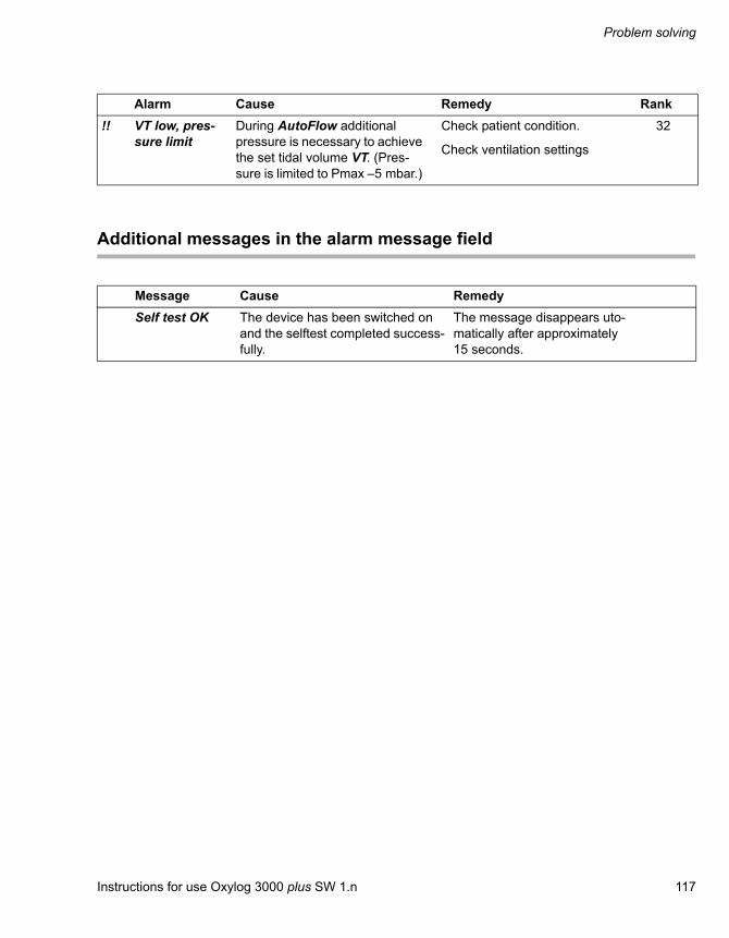
Instructions for use Oxylog 3000 plus SW 1.n 117
Problem solving
Additional messages in the alarm message field
!! VT low, pres-sure limit
During AutoFlow additional pressure is necessary to achieve the set tidal volume VT. (Pres-sure is limited to Pmax –5 mbar.)
Check patient condition.
Check ventilation settings
32
Message Cause Remedy
Self test OK The device has been switched on and the selftest completed success-fully.
The message disappears uto-matically after approximately 15 seconds.
Alarm Cause Remedy Rank

Problem solving
118 Instructions for use Oxylog 3000 plus SW 1.n
Messages in the information field
The numeric values below are examples.
Message Unit1) Cause Explanation/Remedy
PEEP >10 mbar has been set but not confirmed.
The required setting of PEEP >10 mbar is only pos-sible when confirmed via the rotary knob.
Gas consumption = 10 L/min Default display for current gas consumption.
(Battery capacity)
Default display for current battery capacity.
REUS = Adult reusable hose
DISP = Adult disposable hose
PAED = Pediatric disposable hose
Explanation of abbreviation, when selecting the hose type in the Settings window.
Select and confirm hose with rotary knob.
Breathing hose type has not been confirmed.
Select and confirm.
REUS = Reusable Cuvette
DISP = Disposable Cuvette
Explanation of abbreviation, when selecting the CO2 cuvette type in the Settings window.
Press Rotary Knob for Autoset / Exit with Alarm Reset
Activation of Alarms: Auto-set, refer to "Setting alarm limits" on page 87.
After pressing the rotary knob the new alarm limits will be set.
Remove sensor from cuvette then press Rotary Knob
Activation of CO2 zero cali-bration, refer to "CO2 meas-urement (optional)" on page 91.
After removal of the CO2 sensor from the cuvette and pressing the rotary knob, the zero calibration will proceed. Cancel by pressing Alarm Reset.
Place sensor on reference filter, press rotary knob
Activation of CO2 filter check, refer to "CO2 meas-urement (optional)" on page 91.
After mounting the test filter and pressing the rotary knob, the filter check will start. Cancel by pressing Alarm Reset.
Pinsp>=PEEP + 3 mbar PEEP + 3 mbar > Pinsp Set Pinsp > PEEP + 3 mbar.
Confirm PEEP above 10 mbar ?

Instructions for use Oxylog 3000 plus SW 1.n 119
Problem solving
Psupp = 22 mbar Change in Psupp or PEEP.
Psupp is the absolute pres-sure resulting from PEEP + Psupp.
VT = 400 mL or RR = 12 /minTi= 1.5 sFlow = 15 L/min
I:E Change in VT or RR, in venti-lation mode VC-CMV, VC-AC or VC-SIMV.
VT = 400 mL or RR = 12 /minI:E= 1 : 1.5Flow = 15 L/min
Ti
RR = 12 /minTi= 1.5 sTe = 9.5 s
I:E Change in RR, in ventilation mode PC-BIPAP.
RR = 12 /minI:E= 1 : 1.5Te = 9.5 s
Ti
Ti= 1.5 sFlow = 15 L/min
I:E Change in I:E, Ti or Tplat , in ventilation mode VC-CMV, VC-AC or VC-SIMV. Or change in RRapn or VT, in ventilation mode Spn-CPAP.
I:E= 1.5:1Flow = 15 liters per minute
Ti
Ti= 1.5 sTe = 9.5 s
I:E Change in I:E or Ti, in ventila-tion mode PC-BIPAP.
I:E= 1 : 1.5Te = 9.5 s
Ti
1) Unit I:E or Ti is configurable. Refer to the "Customer Service Mode" on page 97.
Message Unit1) Cause Explanation/Remedy

Problem solving
120 Instructions for use Oxylog 3000 plus SW 1.n
Error messages during the device check
Message Cause Explanation/Remedy
System leakage Leakage in breathing circuit and/or in test lung.
Check breathing hoses, breathing valve, flow sensor and test lung for leakage and replace as necessary.
Internal leakage in system Call DrägerService.
No test lung Test lung not connected or major leakage.
Connect test lung.
Check breathing hoses, breathing valve, flow sensor and test lung for leakage and replace as necessary.
Breathing valve inop Breathing valve has malfunctioned. Check correct condition of breathing valve including diaphragm and rub-ber disc; fit a new breathing valve if necessary or use a new disposable breathing circuit.
Pressure measurement inop
The breathing circuit has not been connected correctly.
Connect breathing circuit correctly.
Pressure measurement is not possible.
Call DrägerService.
PEEP-valve inop Internal leakage in system Check breathing hoses, breathing valve, flow sensor and test lung for leakage and replace as necessary.
Device defective Call DrägerService.
Patient flow measure-ment inop
Flow measurement implausible Replace the flow sensor. Call DrägerService.
Hose Detection inop The device check failed on the hose detection.
Connect a different breathing hose or select a different hose type.
Detected hose differs from selected hose
The hose that is detected differs from the selected hose type, or flow measuring lines incorrectly posi-tioned.
Connect a different breathing hose or select a different hose type.
Check measuring lines The flow measuring lines are incorrectly connected.
Connect the flow measuring lines correctly.

Instructions for use Oxylog 3000 plus SW 1.n 121
Cleaning, Disinfection and Sterilization
Cleaning, Disinfection and Sterilization
Disassembly . . . . . . . . . . . . . . . . . . . . . . . . . 122
Disassembling the CO2 sensor and CO2 cuvette . . . . . . . . . . . . . . . . . . . . . . . . . . . . . . 122Disassembling the reusable breathing circuit for adults. . . . . . . . . . . . . . . . . . . . . . . . . . . . . 122Removing the disposable breathing circuit for adults . . . . . . . . . . . . . . . . . . . . . . . . . . . . . . . 124Removing the disposable breathing circuit for pediatric patients . . . . . . . . . . . . . . . . . . . . . . 124
Information on reprocessing. . . . . . . . . . . . 125
Reprocessing procedure . . . . . . . . . . . . . . . 125
Classification of medical devices . . . . . . . . . . 125Uncritical medical devices . . . . . . . . . . . . . . . 125Semicritical medical devices. . . . . . . . . . . . . . 126Visual inspection. . . . . . . . . . . . . . . . . . . . . . . 128Sterilization . . . . . . . . . . . . . . . . . . . . . . . . . . . 128
Reprocessing list . . . . . . . . . . . . . . . . . . . . . 129
Assembling parts . . . . . . . . . . . . . . . . . . . . . 129

Cleaning, Disinfection and Sterilization
122 Instructions for use Oxylog 3000 plus SW 1.n
Disassembly
Disassembling the CO2 sensor and CO2 cuvette
1 Disconnect the CO2 sensor connector from the device.
2 Remove the CO2 sensor (B) from the CO2 cuvette (C).
3 Remove the CO2 cuvette (C) from the flow sensor (D).
4 Remove the angled connector (A) from the cuvette (C).
Disassembling the reusable breathing circuit for adults
1 Disconnect the breathing hose (A) from the expiratory port.
2 Detach the flow measuring lines (B) from the connectors.
05
2
A
BC D
04
6
B
A
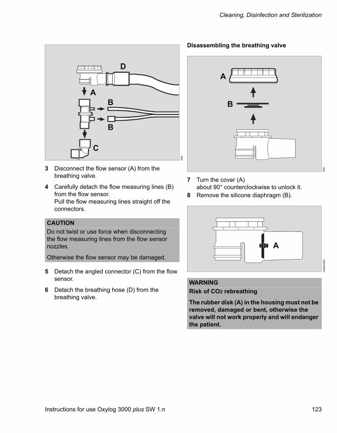
Instructions for use Oxylog 3000 plus SW 1.n 123
Cleaning, Disinfection and Sterilization
3 Disconnect the flow sensor (A) from the breathing valve.
4 Carefully detach the flow measuring lines (B) from the flow sensor.Pull the flow measuring lines straight off the connectors.
5 Detach the angled connector (C) from the flow sensor.
6 Detach the breathing hose (D) from the breathing valve.
Disassembling the breathing valve
7 Turn the cover (A) about 90° counterclockwise to unlock it.
8 Remove the silicone diaphragm (B).
04
4
CAUTION
Do not twist or use force when disconnecting the flow measuring lines from the flow sensor nozzles.
Otherwise the flow sensor may be damaged.
B
A
C
D
B
04
5ru
bb
erd
isc
WARNING
Risk of CO2 rebreathing
The rubber disk (A) in the housing must not be removed, damaged or bent, otherwise the valve will not work properly and will endanger the patient.
A
B
A

Cleaning, Disinfection and Sterilization
124 Instructions for use Oxylog 3000 plus SW 1.n
Removing the disposable breathing circuit for adults
1 Disconnect flow measuring lines (A and B).
2 Disconnect the breathing hose (C).
3 Correctly dispose of the complete disposable breathing circuit. Refer to the chapter "Disposal" on page 137.
Removing the disposable breathing circuit for pediatric patients
1 Disconnect flow measuring lines (A and B).
2 Disconnect the breathing hose (C).
3 Correctly dispose of the complete disposable breathing circuit. Refer to the chapter "Disposal" on page 137.
04
7
CAUTION
The disposable breathing circuit must not be cleaned, disinfected or sterilized: it cannot withstand high temperatures and may be damaged.
A BC
07
63
71
70
-2
CAUTION
The disposable breathing circuit must not be cleaned, disinfected or sterilized: it cannot withstand high temperatures and may be damaged.
A
C
B
Instructions for use Oxylog 3000 plus SW 1.n 125
Cleaning, Disinfection and Sterilization
Information on reprocessing
Observe the hospital hygiene regulations.
Reprocess the device after every patient.
The reprocessing recommendations do not exempt staff from the obligation to adhere to the hygiene requirements and directives on occupational health and safety relating to the reprocessing of medical devices.
To ensure the professional reprocessing of medical devices, the recommendations provided by the Robert Koch Institute in "Demands on Hygiene in Reconditioning Medical Devices" must be followed.
Reprocessing procedure
For the reprocessing list, refer to section "Reprocessing list" on page 129.
Classification of medical devices
For reprocessing, the medical devices and components are classified by their way of application and the risk resulting from it:
– Non-critical medical devices: Surfaces accessible to the user, e. g. device surfaces, cables
– Semicritical medical devices: Parts conducting breathing gas, e.g. breathing hoses, masks
Referring to its reprocessing, this medical device belongs to the group of non-critical medical devices.
Non-critical medical devices
Testing of procedures and agents
The cleaning and disinfection of medical devices has been tested with the following procedures and agents. The following agents showed good material compatibility and effectiveness at the time of the test:
Manual cleaning:
– For device surfaces:Neoform MED AF by Dr. Weigert(concentration: 2 %)
Manual disinfection and simultaneous cleaning
Use disinfectants that are approved nationally and are suitable for the reprocessing procedure being applied.
CAUTION
Risk of infection
The device must be cleaned and disinfected after every use, to prevent possible infection.
Wear protective clothing, eye protection etc. while carrying out reprocessing.
WARNING
Single-use articles have been developed, tested and manufactured for single use only. Disposable products must not be reused, reprocessed, or sterilized. Reuse, reprocessing or sterilization can lead to a failure of the accessories and cause injuries to the patient.

Cleaning, Disinfection and Sterilization
126 Instructions for use Oxylog 3000 plus SW 1.n
Dräger recommends using a surface disinfectant from the list above. Other disinfectants are used at own risk.
Dräger points out that oxygen- and chlorine-releas-ing agents may cause color change in some mate-rials. This is not an indication that the product is not functioning correctly.
At the time of validation, the disinfectants listed above showed material compatibility.
The manufacturers of the surface disinfectants have verified at least the following spectra of activity:
– Bactericidal
– Yeasticidal
– Virucidal or virucidal against enveloped viruses
Observe the specifications of the surface disinfectant manufacturers.
Carry out manual cleaning and disinfection
Remove dirt immediately with a wipe soaked in disinfectant.
1 Carry out surface disinfection.
2 After contact time, remove disinfectant residues.
Semicritical medical devices
Testing of procedures and agents
The cleaning and disinfection of medical devices has been tested with the following procedures and agents. The following agents showed good material compatibility and effectiveness at the time of the test:
Manual cleaning:
– For the breathing valve and hoses:Neodisher LM2 by Dr. Weigert(concentration: 2 %)
– Flow sensor:Sekusept Powder classic by Ecolab(concentration: 4 %)
Manual disinfection:
– Korsolex extra by Bode Chemie(concentration: 3 %)
Machine cleaning and disinfection:
Neodisher Forte MediClean from Dr. Weigert(for thermal disinfection at 93 °C (199 °F) for 10 minutes)
Class of active ingredient
Product name Manufacturer
Chlorine-releasing agents
Actichlor® plus Ecolab
Klorsept® 17 Medentech
BruTab 6S Brulin
Oxygen-releasing agents
Descogen® Liquid
Antiseptics
Descogen® Liquid
Dismozon® plus Bode chemie
Dismozon® pur
Oxycide® Ecolab USA
Perform® Schülke & Mayr
Virkon® DuPont
Quarternary ammonium compounds
Mikrozid® sensitive liquid1)
1) Virucidal against enveloped viruses
Schülke & Mayr
Mikrozid® sensitive wipes1)
Aldehydes Buraton® 10 F Schülke & Mayr
WARNING
Penetrating liquid may cause malfunction of or damage to the device, which may endanger the patient. Only wipe-disinfect items and make sure no liquids penetrate into the device.

Instructions for use Oxylog 3000 plus SW 1.n 127
Cleaning, Disinfection and Sterilization
Manual cleaning
Manual cleaning should preferably be carried out under running water or with commercially available cleaning agents based on mild alkaline compounds.
Carry out manual cleaning
1 Wash off visible soilings under running water. Using an ultrasound cleaner improves cleaning results.
2 Use cleaning agents in accordance with manufacturer’s specifications. Make sure that all surfaces to be cleaned can be efficiently reached.
– Place parts bubble-free into the solution for approx. 20 minutes.
– Agitate all parts thoroughly in the solution at the beginning and at the end of the storage. Brush all parts of the breathing valve.
– When rinsing hoses, let the solution flow through the entire hose by lifting and lowering it.
– Rinse the connectors of the flow sensor and the red rubber disc several times with the solution, e. g., by using a syringe.
– Squeeze the silicone diaphragm several times in the solution.
3 Rinse items under running water until cleaning agent residue is no longer discernible.
4 Inspect items for visible soiling and damage. If necessary, repeat manual cleaning.
Manual disinfection
Manual disinfection should preferably be carried out with disinfectants based on aldehydes or quarternary ammonia compounds.
Observe the applicable country-specific listings for disinfectants. The list of the German Association for Applied Hygiene (Verbund für Angewandte Hygiene VAH) applies in German-speaking countries.
The composition of the disinfectant is the responsibility of the manufacturer and can change over time.
Strictly observe the manufacturer’s information on the disinfectant.
Carry out manual disinfection
1 Disinfect items by immersing bubble-free for approx. 30 minutes.
2 Carry out manual cleaning as described in step 2 of "Carry out manual cleaning" on page 127.
3 After contact time, rinse items under running water until disinfectant residue is no longer discernible.
4 Inspect items for visible soiling and damage. If necessary, repeat manual disinfection.
5 Thoroughly shake out residual water. Allow items to dry thoroughly.
Machine cleaning and disinfection
Use washer-disinfector in accordance with EN ISO 15883, preferably with a cart for anesthesia and ventilation accessories, for automatic cleaning and disinfection. Use mildly alkaline or enzymatic (with neutral pH) cleaning agent. Strictly observe the manufacturer’s information on the cleaning agent.
Carry out machine cleaning and disinfection
1 Strictly observe instructions for use of washer-disinfector.
2 Position items so that all interior spaces are completely flushed and water can drain off freely.
– Connect hoses to suitable nozzle of the carriage in the washer-disinfector and place them evenly.

Cleaning, Disinfection and Sterilization
128 Instructions for use Oxylog 3000 plus SW 1.n
– Connect breathing valve (without cover and silicone diaphragm) with a short breathing hose (e.g., 35 cm silicone breathing hose, order no. 2165619) to a suitable nozzle of the carriage in the washer-disinfector.
3 Use suitable cleaning agent.
4 Select suitable program (preferably anesthesia program).
– Cleaning must be carried out at 40 °C to 60 °C (104 °F to 140 °F) for at least 5 minutes.
– Thermal disinfection must be carried out at 80 °C to 95 °C (176 °F to 203 °F) and with corresponding contact time.
5 Carry out final rinsing with deionized water.
6 Immediately remove items from the washer-disinfector.
7 Inspect items for visible soiling and damage. If necessary, repeat program or carry out manual cleaning and disinfection.
8 Allow items to dry thoroughly.
Visual inspection
Inspect all items for damage and wear, e.g. cracking, embrittlement or pronounced hardening, and residual soiling.
Sterilization
Sterilization frees living microorganisms from semicritical medical devices and removes residual water from the interior spaces of its items.
Only sterilize cleaned and disinfected items.
Use a vacuum steam sterilizer (in accordance with DIN EN 285), preferably with fractional vacuum.
The recommended sterilization temperature and time is 134 °C for 5 minutes.
CAUTION
Even accessories designed to be reused have a limited service life. Handling and reprocessing can increase wear and markedly shorten service life (e.g., disinfectant residues can attack the material more intensely during autoclaving). If signs of wear become visible, such as cracks, deformation, discoloration, peeling, etc., affected accessories must be replaced.
CAUTION
Do not sterilize parts in ethylene oxide.
Ethylene oxide may diffuse into the parts and cause damage to health.

Instructions for use Oxylog 3000 plus SW 1.n 129
Cleaning, Disinfection and Sterilization
Reprocessing list
Applicable to non-infectious patients.
The list contains approximate values only. The instructions of the hospital’s infection control officer shall prevail and must be observed by the user!
Assembling parts
– Reassemble, refer to "Assembly" on page 35 for information.
– Connect to the power supply and gas supply, refer to "Assembly" on page 35 for information.
– Check readiness for operation, refer to "Preparation" on page 51 for information.
Components which can be reprocessed
Recommended reprocessing intervals
Machine cleaning and disinfection
Manual Sterilization
Cleaning Disinfection
Oxylog 3000 plus unit and O2 hoses
Per patient /if soiled
No Outside only
Outside only No
Reusable breathing cir-cuit
Per patient /if soiled
Yes Possible Possible Yes
CO2 sensor Per patient /if soiled
No Outside only
Outside only No
Reusable cuvette of the CO2 sensor
Per patient /if soiled
Yes Yes Yes Yes
Test filter for CO2 sensor If soiled No Yes Yes No

130 Instructions for use Oxylog 3000 plus SW 1.n
This page has been left blank intentionally.

Instructions for use Oxylog 3000 plus SW 1.n 131
Maintenance
Maintenance
Maintenance intervals of Oxylog 3000 plus 132
Definition of Maintenance Concepts. . . . . . . . 132
Inspection . . . . . . . . . . . . . . . . . . . . . . . . . . . 133
Safety checks . . . . . . . . . . . . . . . . . . . . . . . . 133
Preventive maintenance . . . . . . . . . . . . . . . 134
Maintenance schedule . . . . . . . . . . . . . . . . . . 134
Repair . . . . . . . . . . . . . . . . . . . . . . . . . . . . . . 134
In case of ventilator failure . . . . . . . . . . . . . 135

Maintenance
132 Instructions for use Oxylog 3000 plus SW 1.n
Maintenance intervals of Oxylog 3000 plus
Definition of Maintenance Concepts
This chapter describes the maintenance measures required to maintain the proper functioning of the medical device. Maintenance measures must be performed by the personnel responsible.
Carry out maintenance procedures only when no patient is connected to the device.
Keep a record on all maintenance procedures carried out.
m
CAUTIONIn order to avoid malfunctioning of the device, maintenance must be carried out by properly trained maintenance personnel.
WARNING
Risk of infection
Users, maintenance personnel and trained experts may become infected with pathogenic germs.
Disinfect and clean device or device parts before any maintenance measures and also before returning the medical device for repair.
WARNING
Risk of electric shock
Current-carrying components are located under the cover.
– Do not remove the cover.
– Maintenance measures must be performed by the personnel responsible. Dräger recommends DrägerService to perform these measures.
Concept Definition
Maintenance Appropriate measures intended to retain the functional integrity of a medical device.
Inspection Measures intended to determine and assess the actual state of a medical device
Preventive maintenance Repeated indicated measures intended to retain the functional integrity of a medical device.
Repair Measures intended to restore the functional integrity of a medical device after the failure of a device function

Instructions for use Oxylog 3000 plus SW 1.n 133
Maintenance
Inspection
Inspections must be carried out regularly according to the following guidelines and within the specified intervals.
Safety checks
Safety checks are no substitute for preventive maintenance measures (including preventive replacement of wear parts) as identified by the manufacturer.
Scope
1 Check the accompanying documents:
– Instructions for use present.
2 Check components and accessories for completeness according to the supplied instructions for use when the product is ready for operation.
3 Check that the device combination is in good condition:
– Labels complete and legible.
– No damage.
4 Check electrical safety:
– In accordance with IEC 62353.
5 Check safety functions:
– Correct functioning of the safety valve: max pressure 90 mbar.
– Correct functioning of the emergency air valve.
– Correct functioning of the mains supply failure alarm.
– Monitoring of the supply pressure.
– Check the high airway pressure alarm.
– Check the breathing circuit integrity alarm.
– Check the proper functioning of the power indicators.
6 When operating in a helicopter, make a visual check of the contacts to the battery and replace them as necessary.
7 Perform a device check according to the instructions for use.
Checks Interval Personnel responsible
Inspection and safety checks1) Every 2 years Maintenance personnel
1) Designation applies to the Federal Republic of Germany; corresponds to the “Recurring safety inspection” in the Federal Republic of Austria.
WARNING
Risk of medical device failure
If safety checks are not performed on a regular basis, the proper operation of the medical device can be compromised.
Perform safety checks at the indicated intervals.

Maintenance
134 Instructions for use Oxylog 3000 plus SW 1.n
Preventive maintenance
Maintenance schedule
Repair
For repairs, Dräger recommends engaging DrägerService and using original Dräger parts.
WARNING
Risk of faulty components
Device failure is possible due to wear or material fatigue of the components.
To maintain the proper operation of all components, this device must undergo inspection and preventive maintenance at specified intervals.
WARNING
Risk of electric shock
Before performing any maintenance work, disconnect all electrical connectors and gas connectors from power supply and gas supply.
Component Interval Task Personnel responsible
Dust filter Every 2 years Replace1) Maintenance personnel
Internal rechargeable battery
– Every 2 years
– When the battery no longer remains charged for the specified operating time2)
Replace Users
Device Every 2 years Inspection and pre-ventive maintenance
Maintenance personnel
1) The dust filter can be treated as household waste.2) Refer to "Technical Data" section for battery operating time.

Instructions for use Oxylog 3000 plus SW 1.n 135
Maintenance
In case of ventilator failure
WARNING
Never operate a ventilator if it has suffered physical damage or does not seem to operate properly.
In this case, always engage factory trained or authorized expert personnel to service the device.

136 Instructions for use Oxylog 3000 plus SW 1.n
This page has been left blank intentionally.

Instructions for use Oxylog 3000 plus SW 1.n 137
Disposal
Disposal
Disposing of the medical device. . . . . . . . . 138
Disposal instructions . . . . . . . . . . . . . . . . . . 138
Disposingof the medical device and power supplies . . . . . . . . . . . . . . . . . . . . . . . . . . . . . 138Disposing of non-rechargeable batteries . . . . 138Disposingof the breathing circuits and the CO2 cuvettes . . . . . . . . . . . . . . . . . . . . . . . . . 138

Disposal
138 Instructions for use Oxylog 3000 plus SW 1.n
Disposing of the medical device
When disposing of the medical device:
Have the medical device appropriately disposed of by the responsible waste disposal company.
Observe the applicable laws and regulations.
For countries subject to the EU Directive 2002/96/EC
This device is subject to EU Directive 2002/96/EC (WEEE). In order to comply with its registration according to this directive, this device may not be disposed of at municipal collection points for waste electrical and electronic equipment. Dräger has authorized a company to collect and dispose of this device. To initiate collection or for further information, visit Dräger on the Internet at www.draeger.com. Use the Search function with the keyword "WEEE" to find the relevant information. If access to Dräger's website is not possible, contact the local Dräger organization.
Disposal instructions
Disposing of the medical device and power supplies
When disposing of the medical device:
– Consult the responsible waste disposal company for appropriate disposal.
Observe the applicable laws and regulations.
Disposing of non-rechargeable batteries
Do not recharge batteries.
The medical device battery contains pollutant substances.
Observe the applicable laws and regulations for battery disposal.
Disposing of the breathing circuits and the CO2 cuvettes
Always follow local regulations governing the disposal of breathing circuits and CO2 cuvettes in accordance with applicable hospital/emergency service standards.WARNING
Risk of explosion and of chemical burns.
Improper handling of batteries can result in explosions and chemical burns.
Do not throw batteries into fire. Do not force batteries open.

Instructions for use Oxylog 3000 plus SW 1.n 139
Technical data
Technical data
Ambient conditions . . . . . . . . . . . . . . . . . . . 140
During operation. . . . . . . . . . . . . . . . . . . . . . . 140During storage and transportation . . . . . . . . . 140
Settings . . . . . . . . . . . . . . . . . . . . . . . . . . . . . 141
Performance characteristics . . . . . . . . . . . . 142
Measured values and curves display . . . . . 144
Airway pressure measurement. . . . . . . . . . . . 144Flow measurement . . . . . . . . . . . . . . . . . . . . . 144CO2 measurement . . . . . . . . . . . . . . . . . . . . . 144Frequency measurement . . . . . . . . . . . . . . . . 144Curve display . . . . . . . . . . . . . . . . . . . . . . . . . 144
Monitoring . . . . . . . . . . . . . . . . . . . . . . . . . . . 145
Expiratory minute volume MVe. . . . . . . . . . . . 145Airway pressure, Paw. . . . . . . . . . . . . . . . . . . 145Apnea alarm time Tapn. . . . . . . . . . . . . . . . . . 145Apnea . . . . . . . . . . . . . . . . . . . . . . . . . . . . . . . 145Rate, RRsp. . . . . . . . . . . . . . . . . . . . . . . . . . . 145Leakage . . . . . . . . . . . . . . . . . . . . . . . . . . . . . 145Data communication (option) . . . . . . . . . . . . . 146
Operating data . . . . . . . . . . . . . . . . . . . . . . . 146
Power supply . . . . . . . . . . . . . . . . . . . . . . . . . 146Gas supply . . . . . . . . . . . . . . . . . . . . . . . . . . . 148
Device specifications . . . . . . . . . . . . . . . . . . 148
Materials used. . . . . . . . . . . . . . . . . . . . . . . . 150
EMC declaration . . . . . . . . . . . . . . . . . . . . . . 151
General Information . . . . . . . . . . . . . . . . . . . . 151Electromagnetic environment . . . . . . . . . . . . . 152Recommended separation distances from wireless communication devices . . . . . . . . . . 152

Technical data
140 Instructions for use Oxylog 3000 plus SW 1.n
WARNING
Do not use the device outside the specified environmental and supply conditions, as the device may not operate according to its specifications and may become inoperative.
Ambient conditions
During operationTemperature –20 to +50 °C
Ambient pressure 570 to 1200 hPa
Ambient pressure for CO2 sensor 570 to 1100 hPa
Automatic atmospheric pressure compensation within this pressure range
Altitude up to 4600 m
Ambient pressure for AC/DC power pack
700 to 1200 hPa
Temperature 0 to 50 °C
Altitude up to 3000 m
Relative humidity 5 to 95 % (no condensation)
During storage and transportationVentilator without replaceable battery, with reusable breathing circuit
Temperature –40 to +75 °C
Ambient pressure 570 to 1200 hPa
Ambient pressure for CO2 sensor 115 to 1100 hPa
Relative humidity 5 to 95 % (no condensation)
Time required from maximum/mini-mum storage temperature to reach operating conditions
60 minutes
Adult and pediatric breathing circuits, disposable
Temperature –20 to +50 °C
Ambient pressure 570 to 1200 hPa
Relative humidity 5 to 95 % (no condensation)
Replaceable battery
Temperature –20 to +50 °C(preferred long-time storage tempera-ture <30 °C)
Ambient pressure 570 to 1200 hPa
Relative humidity 5 to 95 % (no condensation)

Instructions for use Oxylog 3000 plus SW 1.n 141
Technical data
Settings
Ventilation modes VC-CMV, VC-AC, VC-SIMV, VC-SIMV/PS, Spn-CPAP, Spn-CPAP/PS, PC-BIPAP, PC-BIPAP/PSOptional: AutoFlow for VC-CMV, VC-AC and VC-SIMV (/PS)
Respiratory rate RR 2 to 60/min (VC-SIMV, PC-BIPAP)5 to 60/min (VC-CMV, VC-AC)12 to 60/min for apnea ventilation
Ventilation time ratio I:E 1:100 to 50:1
Inspiratory time Ti 0.2 to 10 s
Tidal volume VT 0.05 to 2.0 L, BTPSMeasured values referred to the conditions of the patient's lungs, body temperature 37 °C, airway pressure, water-vapor-saturated gas.
Accuracy of setting ±15 % of the set value or ±25 mL, whichever greater(adult breathing hose).
±15 % of the set value or ±15 mL, whichever greater(pediatric breathing hose).
Inspiratory pressure Pinsp PEEP +3 to +55 mbar
O2 concentration 40 to 100 Vol%
Accuracy of setting ±10 Vol%. The actual value depends on the inspiratory flow1) and mean air-way pressure.
Positive end-expiratory pressure PEEP 0 to 20 mbar, no negative pressure.
Trigger sensitivity (flow trigger) 1 to 15 L/min

Technical data
142 Instructions for use Oxylog 3000 plus SW 1.n
Pressure support Psupp 0 to 35 mbar (relative to PEEP)
Pressure rise time for pressure sup-port
slow (1 s), standard (0.4 s), fast.
Inspiration termination of pressure supported strokes, as a percentage of peak inspiratory flow (PIF)(Insp.term.%PIF)
5 to 50 %
Alarm limit ranges
Alarm Alarm limit range
MVe 2 to 41 L/min
MVe 0.5 to 40 L/min
RRspon 10 to 100/min
etCO2 1 to 100 mmHg / 0.1 to 13.3 kPa / 0.1 to 13.3 Vol%
etCO2 0 to 100 mmHg / 0 to 13.3 kPa / 0 to 13.3 Vol%
1) see O2 concentration, page 78
Performance characteristics
Control principle Time-cycled, volume-constant, pressure-controlled
Maximum inspiratory flow 100 L/min1)
Device compliance
with adult breathing hose, 1.5 m
<1 mL/mbar
with adult breathing hose, 3 m
<2 mL/mbar
with pediatric breath-ing hose, 1.9 m
<0.7 mL/mbar
Inspiratory and expiratory resistance of the device with adult breathing circuit
<6 mbar at 60 L/min
<4 mbar at 30 L/min
<2 mbar at 5 L/min
Inspiratory and expiratory resistance of the device with pediatric breathing circuit
<5 mbar at 30 L/min
<2 mbar at 5 L/min

Instructions for use Oxylog 3000 plus SW 1.n 143
Technical data
Nominal flow Disposable breathing circuit for adults, 1.5 m
Inspiratory 21 L/min at 2 mbarExpiratory 10 L/min at 2 mbar
Disposable breathing circuit for adults, 3.0 m
Inspiratory 20 L/min at 2 mbarExpiratory 10 L/min at 2 mbar
Reusable breathing circuit for adults, 1.5 m
Inspiratory 22 L/min at 2 mbarExpiratory 16 L/min at 2 mbar
Reusable breathing circuit for adults, 3.0 m
Inspiratory 21 L/min at 2 mbarExpiratory 15 L/min at 2 mbar
Disposable breathing circuit for pediatric patients
Inspiratory 12 L/min at 2 mbarExpiratory 7 L/min at 2 mbar
Dead space including flow sensor, but excluding accessories such as filter, HMEs and CO2 cuvette
Approx. 35 mL2)
(reusable breathing circuit for adults)Approx. 30 mL2)
(disposable breathing circuit for adults)Approx. 15 mL2)
(Disposable breathing circuit for pediatric patients)
Dead space of CO2 cuvette
Approx. 4 mL (CO2 cuvette)Approx. 1.5 mL (CO2 cuvette for pediatric patients))
Supplementary functions
Demand valve Opens the breathing system upon failure of the gas supply, permits spontaneous breathing with ambient air.
Relief valve Opens the breathing system in case of device malfunction at approximately 80 mbar.
Patient connection 22 mm ISO conical connector
1) At a supply pressure >350 kPa.The maximum inspiratory flow is reduced to 80 L/min at supply pressures <350 kPa and to 39 L/min at supply pressures <280 kPa.
2) When using an accessory with a female connector, add 2 mL to the breathing circuit dead space.

Technical data
144 Instructions for use Oxylog 3000 plus SW 1.n
Measured values and curves display
Airway pressure measurementRange 0 to 100 mbar
Resolution 1 mbar
Accuracy ±(2 mbar + 2 % of measured value)
Flow measurementMinute volume MVe
Range 0 to 99 L/min, BTPS
Resolution 0.1 L/min
Accuracy ±15 of measured value, or ±0.4 L/min, whichever is greater.
Tidal volume VTe
Range 0 to 5000 mL, BTPS
Resolution 1 mL
Accuracy ±15 % of the measured value or ±20 mL, whichever greater (adult breathing hose).
±15 % of the measured value or ±15 mL, whichever greater (pediatric breathing hose).
CO2 measurementRange 0 to 120 mmHg / 0 to 15.8 Vol% / 0 to 16.0 kPa
Resolution 1 mmHg / 0.1 Vol% / 0.1 kPa
Total system response time
200 ms
Frequency measurementRange 0 to 99/min
Resolution 1/min
Accuracy ±1/min
Curve displayAirway pressure Paw (t) –10 to 100 mbar
Flow (t) –120 to 120 L/min
CO2 –5 to 120 mmHg / –1 to 16 Vol% / –1 to 16 kPa

Instructions for use Oxylog 3000 plus SW 1.n 145
Technical data
Monitoring
Expiratory minute volume MVeAlarm, upper alarm limit When the upper alarm limit has been exceeded.
Range of settings 2 to 41 L/min
Alarm, lower alarm limit When the lower alarm limit has been violated.
Range of settings 0.5 to 40 L/min
Airway pressure, PawAlarm, upper alarm limit When value Pmax is exceeded.
Range of settings 20 to 60 mbar
Alarm, lower alarm limit When the pressure difference between inspiratory and expiratory phases is less than 5 mbar for at least 20 seconds.Or When the set pressure value is not attained within 10 seconds.
Apnea alarm time TapnAlarm When respiratory activity is no longer detected.
Range of settings 15 to 60 s
ApneaAlarm When no respiratory phase change has been
detected for >12 seconds and Tapn is off.
Rate, RRspAlarm, upper alarm limit > 25 seconds above the set value
Range of settings 10 to 100/min
LeakageAlarm Only with NIV off in VC modes:
When VTe <60 % of VTi over the last 25 seconds or 8 respiratory cycles

Technical data
146 Instructions for use Oxylog 3000 plus SW 1.n
Data communication (option)Exported data Measured values
CurvesAlarmsAlarms settingsUser settings
For the data communication protocol contact your local DrägerService.
Baud rate 19200
Data bits 8
Parity Even
Stop bit 1
Operating data
Power supplyPower supply
Oxylog 3000 plusInput voltage
24 V ±6 VDC
Power supplies (AC/DC power pack and DC/DC converter) are specified as part of the Oxylog 3000 plus.
Power consumption
With battery charging maximum 2.4 A at 19 VDC
Operating time with a new and fully charged internal battery without mains power supply
– in typical ventilation without CO2 sensor, reduced display brightness
– in typical ventilation
Approx. 9.5 hours
Approx. 7.5 hours
Battery type Lithium ion battery
Charging time Approx. 4 hours
The specified charging time applies when recharg-ing the battery to a level of approx. 90 % after it has been depleted. Charging of a completely depleted battery is only possible when the ventilator is switched OFF.

Instructions for use Oxylog 3000 plus SW 1.n 147
Technical data
Permissible ambient temperature during charging 0 °C to 35 °C
Indication of battery capacity In 25 % increments
Accuracy of the capacity indication The indicated capacity is determined by the battery itself. The accuracy depends on the type and man-ufacturer and may deteriorate with frequent partial discharge and during operation in extreme temper-atures. The internal battery is only reconditioned after being discharged completely and recharged at room temperature 25 °C.Consequently, the criteria for the !!! Int. battery discharged and !! Charge int. battery alarm mes-sages are derived from the measurement of the battery voltage. The capacity indicated at this moment may differ from the actual capacity of the internal battery.
Battery storage duration The internal battery must always be removed from the ventilator for storage and recharged completely after 12 months at the latest (e. g. in the external battery charging station). To maintain the ideal charging capacity, the battery should be stored with a charge of 40 to 50 %.
AC/DC power pack Protection class (as defined in IEC 60601-1)
Class II
Degree of protection IP22
Input 100 to 240 V~ / 50 to 60 Hz / 1.0 A
Output 19 V ±0,5 V / 4.47 A (–20 °C to 40 °C) /3.5 A (40 °C to 50 °C)
To isolate the ventilator system from mains, discon-nect the power cable from the power socket.
The intended use of the AC/DC power pack is in stationary situations (e.g. in hospitals or fire sta-tions).
DC/DC converter Protection class IP42
Temperature range –20 °C to +50 °C
Input 12 / 24 / 28 VDC; 5 A / 2.5 A / 2.1 A
Output 19 V ±0.5 V / 2.6 A
The intended use of the DC/DC converter is in vehi-cles.

Technical data
148 Instructions for use Oxylog 3000 plus SW 1.n
Gas supply From a central gas supply system or from an O2 cylinder.
O2 supply pressure 270 kPa to 600 kPa at 100 L/min
Supply gas Medical oxygen
Connector for O2 supply either: NIST1) to EN 739 / ISO5359, orDISS2) to CGA V5-1989, orN-F3) S90-116
WARNING
Only use medical grade oxygen.
Gas cylinders and pres-sure reducers
WARNING
Only use compressed gas cylinders and pressure reducers, which comply with all applicable regulations and have been approved.
Pressure reducer Must have a blow-off valve on the output side to limit the outlet pressure to approximately 1000 kPa in the event of a fault.
Gas consumption for internal control
Average 0.5 L/min
Accuracy of gas consumption indication
15 % or ±1 L/min, whichever is greater.
1) NIST = Non-Interchangeable Screw-Threaded2) DISS = Diameter Index Safety Systems3) N-F = Norme française
Device specifications
Sound pressure level of typical ventilation <45 dB (A) at a distance of 1 m.
Sound pressure level of alarm signals 52 to 67 dB (A) at a distance of 1 m.
Dimensions (W × H × D)
Basic unit 294 × 188 × 179 mm (without handle and protection bracket)
Protection bracket 75 mm (in addition to the width of the basic unit)
AC/DC power pack 150 × 37 × 64 mm
DC/DC converter 160 × 35 × 60 mm
Weight
Basic unit without internal battery
Approx. 5.3 kg

Instructions for use Oxylog 3000 plus SW 1.n 149
Technical data
Basic unit with internal bat-tery
Approx. 5.8 kg
AC/DC power pack Approx. 0.6 kg
DC/DC converter Approx. 0.6 kg
Center of gravity (basic unit)
Width from left 152 mm
Height from bottom 83 mm
Depth from rear 82 mm
Display
Technology Electroluminescence (EL)
Pixels 240 x 128
Visible area 108 x 56 mm
Electromagnetic Compatibility (EMC) Complies with IEC 60601-1-2, EN 794-3 (36,101), ISO 10651-3 (36,202,2,1) and UN Regulation No. 10 (for the power supply unit), with respect to EMC for use in motor vehicles, equivalent to European Commission Directive 2004/104/EC.
Complies with RTCA DO-160 with respect to EMC for use in aircraft and helicopters.
Classificationaccording to Directive 93/42/EEC
Class IIb
UMDNS-codeUniversal Medical Device Nomenclature System
18 – 098
Protection class, breathing circuits (disposable or reusable), including CO2 sensor, endotracheal tubes, or masks
Type BF (body floating, defibrillation-proof)
Protection class against ingress of liquids IPX4, device is splashproof from all directions
Protection class of the CO2 sensor IP64
Defibrillation recovery time 0 s

Technical data
150 Instructions for use Oxylog 3000 plus SW 1.n
Materials used
Housing, Oxylog 3000 plus Acrylonitrile styrene acrylate/polycarbonate (ASA/PC)
Thermoplastic Copolyester Elastomer (TPC)
Housing, AC/DC power pack Polycarbonate (PC)
Housing, DC/DC converter Polycarbonate (PC)
Touch sensitive keypad on ventilator Polyester film
NOTE
All Dräger breathing hoses are made without use of natural rubber latex.
Reusable breathing circuit for adults
Breathing hose, flow measuring lines
Silicone rubber
Housing of flow sensor, breathing valve
Polysulfone (PSU)
Vane in flow sensor Stainless steel
Diaphragms in breathing valve
Silicone rubber
Disposable breathing circuit for adults
Breathing hose Polyethylene (PE)
Non-return valve Polypropylene (PP), silicone rubber
Breathing valve Polypropylene (PP), silicone rubber
Flow sensor housing Polymethyl methacrylate (PMMA)
Vane in flow sensor Polyester
Patient connection Polyethylene (PE), Polypropylene (PP), K-Resin®, Thermoplastic Polyether Elastomer (TPE)
Disposable breathing circuit for pediatric patients
Breathing hose Ethylene Vinyl Acetate (EVA)
Non-return valve Housing: Polypropylene (PP)Membrane: silicone rubber
Breathing valve Housing: Polypropylene (PP)Membrane: silicone rubber
Flow sensor housing Methacrylate-Acrylonitrile Butadiene Styrene (MABS)
Patient connection Polycarbonate (PC)
Instructions for use Oxylog 3000 plus SW 1.n 151
Technical data
EMC declaration
General Information
The EMC conformity of the Oxylog 3000 plus includes the use of following external cables, transducers and accessories:
– AC/DC power pack
– DC/DC converter
– All-round Wall Holder
– Equipment holder
– Carrying bag
– Quick Power Connector
– Carrying System
– CO2 sensor
– CO2 extension cable
– Data communication cable
This device was tested for electromagnetic compatibility using accessories from the list of accessories. Other accessories may only be used if they do not compromise the electromagnetic compatibility. The use of non-compliant accessories may result in increased electromagnetic emissions or decreased electromagnetic immunity of the device.
This device may be used in the direct vicinity of other devices only if Dräger has approved this device arrangement. If no approval has been given by Dräger, it must be ensured that this device functions correctly in the desired arrangement before use. The instructions for use for the other devices must be followed.
Y-piece Polycarbonate (PC)
Vane in flow sensor Polyethylene terephthalate (PET)
Connectors Polypropylene (PP) and Polycarbonate (PC)
CO2 sensor
Housing Polysulfone
Cable Polyurethane
CO2 cuvette
Disposable K-Resin® SBC
Reusable Polysulfone (PSU) with sapphire windows

Technical data
152 Instructions for use Oxylog 3000 plus SW 1.n
Electromagnetic environment
This device may only be used in environments specified in section "Environment of use" on page 14.
Emissions Compliance
Radiated emissions Class B, group 1 (30 MHz to 1 GHz)
Conducted emissions Class B, group 1 (150 kHz to 30 MHz)
Harmonic emissions(IEC 61000-3-2)
Class A
Voltage fluctuations / flicker (IEC 61000-3-3) Fulfilled
Immunity against Test level and required electromagnetic environment
Electrostatic discharge (ESD)(IEC 61000-4-2)
Contact discharge: ±8 kV
Air discharge: ±15 kV
Fast transient electrical disturbances(bursts) (IEC 61000-4-4)
Power cable: ±2 kV
Longer signal input lines/output lines: ±1 kV
Impulse voltages (surges) (IEC 61000-4-5) Voltage, external conductor – external conductor: ±1 kV
Voltage, external conductor – protective ground conductor: ±2 kV
Magnetic fields at mains frequency (IEC 61000-4-8) 50 Hz: 30 A/m
Voltage dips and short interruptions in the supply voltage (IEC 61000-4-11)
Voltage dips of 30 % to 100 %, 8.3 ms to 5 s, different phase angles
Radiated high-frequency disturbances(IEC 61000-4-3)
26 MHz to 1 GHz: 30 V/m (ISO 10651-3)80 MHz to 2 GHz: 10 V/m (EN 794-3)80 MHz to 2.7 GHz: 3 V/m
Conducted high-frequency disturbances(IEC 61000-4-6)
150 kHz to 80 MHz: 3 V, ISM bands: 6 V
Electromagnetic fields in the vicinity of wireless communication devices
Various frequencies from 385 MHz to 5785 MHz:9 V/m to 28 V/m

Instructions for use Oxylog 3000 plus SW 1.n 153
Technical data
Recommended separation distances from wireless communication devices
WARNING
Risk due to electromagnetic disturbance
Wireless communication devices (e.g., cellu-lar phones) and medical electrical equipment (e.g., defibrillators, electrosurgical devices) emit electromagnetic radiation. When such devices are operated too close to this device or its cables, the functional integrity of this device may be compromised by electromag-netic disturbances. As a result, the patient could be put at risk.
Maintain a distance of at least 0.3 m (1.0 ft) between this device and wireless communica-tion devices to ensure that the essential per-formance of this device is fulfilled.
Maintain an adequate distance between this device and other medical electrical equip-ment.

154 Instructions for use Oxylog 3000 plus SW 1.n
This page has been left blank intentionally.

Instructions for use Oxylog 3000 plus SW 1.n 155
Description
Description
Ventilation modes. . . . . . . . . . . . . . . . . . . . . 156
VC-CMV . . . . . . . . . . . . . . . . . . . . . . . . . . . . . 156VC-AC . . . . . . . . . . . . . . . . . . . . . . . . . . . . . . 156VC-SIMV. . . . . . . . . . . . . . . . . . . . . . . . . . . . . 157PS. . . . . . . . . . . . . . . . . . . . . . . . . . . . . . . . . . 158PC-BIPAP. . . . . . . . . . . . . . . . . . . . . . . . . . . . 159
AutoFlow . . . . . . . . . . . . . . . . . . . . . . . . . . . . 160
Start up behavior of AutoFlow . . . . . . . . . . . . 161
Dead space . . . . . . . . . . . . . . . . . . . . . . . . . . 162
Determining cycle time, inspiratory time and expiratory time . . . . . . . . . . . . . . . . . . . 162
Functional description . . . . . . . . . . . . . . . . . 163
Gas supply . . . . . . . . . . . . . . . . . . . . . . . . . . . 163Inspiration. . . . . . . . . . . . . . . . . . . . . . . . . . . . 163Expiration . . . . . . . . . . . . . . . . . . . . . . . . . . . . 163Safety . . . . . . . . . . . . . . . . . . . . . . . . . . . . . . . 164Software . . . . . . . . . . . . . . . . . . . . . . . . . . . . . 164Monitoring. . . . . . . . . . . . . . . . . . . . . . . . . . . . 164CO2 measurement . . . . . . . . . . . . . . . . . . . . . 164

Description
156 Instructions for use Oxylog 3000 plus SW 1.n
Ventilation modes
VC-CMV
Volume Controlled –Controlled Mandatory Ventilation
In this mode only mandatory volume controlled strokes are delivered to the patient. The ventilation pattern is specified by the settings for tidal volume VT, respiratory rate RR, ventilation time ratio I:E or inspiratory time Ti and PEEP.
At the end of the flow delivery phase, the expiratory valve remains closed until the end of the inspiratory time. This phase, the inspiratory pause, can be identified as the plateau Tplat and is defined as a percentage of the inspiratory time.
VC-AC
Volume Controlled – Assist Control
Assisted ventilation with continuous positive airway pressure.
VC-AC provides volume controlled strokes. These strokes can be synchronized with the patient's spontaneous breathing. The mandatory ventilation pattern is specified as VC-CMV, but the mandatory breath begins when the patient reaches an inspiratory flow corresponding at least to the set flow trigger.
The actual respiratory rate may be higher than the set respiratory rate.
04
1
Paw
Flow
Ti Te
T=
Pplat
1
t
t
PEEP
without plateauwith plateau
RR
Tplat%

Instructions for use Oxylog 3000 plus SW 1.n 157
Description
VC-SIMV
Volume Controlled – Synchronized Intermittent Mandatory Ventilation
VC-SIMV provides a combination of mandatory ventilation and spontaneous breathing. It enables the patient to breathe spontaneously, with the mechanical mandatory breaths providing minimum ventilation. The minimum ventilation is controlled by the two set values of the tidal volume VT and respiratory rate RR and is determined from the product of VT x RR.
The mandatory ventilation pattern results from the ventilation parameters of the tidal volume VT, respiratory rate RR, ventilation time ratio I:E or inspiratory time Ti and plateau time Tplat. To prevent the mandatory breath from being applied during spontaneous expiration, the flow trigger of the ventilator ensures that the breath is triggered in synchrony with the patient's spontaneous inspiratory effort within a fixed time window during expiration.
The trigger window has a duration of 5 seconds. If the expiratory time is less than 5 seconds, the trigger window covers the entire expiratory time minus a minimum expiratory time of 500 ms.
Since the synchronization of the mandatory breath reduces the spontaneous breathing time, which would result in an undesirable increase in respiratory rate, the Oxylog 3000 plus prolongs the spontaneous breathing time of the subsequent breath by the difference T - thus preventing an increase in SIMV frequency. The respiratory rate RR remains constant.
The respiratory rate RR and tidal volume VT set the minimum ventilation –, as in VC-CMV and VC-AC.
During the spontaneous breathing phases, the patient can be assisted with pressure by Pressure Support PS.
Generally the number of mandatory breaths is reduced in the course of weaning the patient off ventilation. This increases the spontaneous breathing time, so that the required total minute volume MV is increasingly supplied by spontaneous breathing.
04
2
Paw
PEEPt
Spontaneousbreathing time
Spontaneousbreathing time + T
Triggerwindow
Synchronizedmandatoryventilation stroke
Unsynchronizedmandatoryventilation stroke
Ti
Set mandatory
cycle time Set mandatory
cycle time
1RR 1
RR

Description
158 Instructions for use Oxylog 3000 plus SW 1.n
PS
Pressure Support (Pressure support)
Pressure Support for insufficient spontaneous breathing.
PS can be used in combination with VC-SIMV, PC-BIPAP and Spn-CPAP. With PS the device supports the inspiration. The patient has control of the spontaneous respiratory rate. During PS strokes, the spontaneously breathing patient is supplied with breathing gas, even if the inspiratory effort is weak.
The Pressure Support is started when the spontaneous inspiratory flow reaches the set flow trigger level. The device then increases the airway pressure up to the preselected pressure Psupp above PEEP, which is adjustable to the condition of the patient.
The are three settings for the rate of pressure increase (slope):
– Steep slope: The pressure rises rapidly, meaning the Oxylog 3000 plus supports spontaneous breathing with a high initial flow.
– Flat slope: The pressure rises slowly, meaning the Oxylog 3000 plus supports spontaneous breathing with a low initial flow. In this case greater inspiratory effort by the patient may be required.
– Medium slope: It is also possible to choose a setting between a high and low initial flow.
The slope and the Psupp above PEEP and the patient's own breathing activity define the inspiratory flow.
PS is terminated:
– When after 100 ms the inspiratory flow falls below the set inspiration termination criterion as percentage of the peak inspiratory flow (Insp.term.%PIF) (and thus Psupp above PEEP is reached), or
– After 4 seconds, if the previous criterion has not been fulfilled.
04
3
PhaseI II
Paw
Insp.Flow
t
t
CPAP
Start of inspiration
max. 4 s
End of inspiration
Inspirationtermination %PIF
PPS
DPSover PEEP

Instructions for use Oxylog 3000 plus SW 1.n 159
Description
PC-BIPAP
Pressure Controlled – Biphasic Positive Airway Pressure
The PC-BIPAP ventilation mode is a pressure controlled / time-cycled ventilation mode, in which the patient can always breathe spontaneously. PC-BIPAP can be described as a time-cycled alternation between two CPAP levels.
The constant option of spontaneous breathing allows the transition from controlled ventilation to independent spontaneous breathing to take place smoothly during the weaning phase, without requiring any change of the ventilation mode. To adapt easily to the patient's spontaneous breathing pattern, the changeover from inspiratory pressure level to expiratory pressure level and visa versa, are synchronized with the patient's spontaneous breathing.
The rate of the changeover is kept constant, even when synchronization occurs via a trigger window. This smooth adaptation to the patient's spontaneous breathing requires less sedation. This means that the patient returns to spontaneous breathing more rapidly.
As in all pressure-controlled ventilation modes, the patient is not prescribed a fixed tidal volume VT. The tidal volume VT results principally from the pressure difference between PEEP and Pinsp and
from the lung compliance. An increase in this pressure difference will cause an increased tidal volume VT.
The measured expiratory tidal volume VTe must be used to set the required difference between PEEP and Pinsp.
Changes in lung compliance and in the airway, as well as active 'fighting' by the patient can lead to changes in tidal volume VT. This is a desired effect in this ventilation mode. Because the tidal volume VT and the resulting minute volume MV are not constant, the alarm limits for minute volume MVe must be set with care.
Setting PC-BIPAP
As with VC-SIMV, the time pattern is set using the basic setting parameters respiratory rate RR and ventilation time ratio I:E or inspiratory time Ti.
The lower pressure level is set with the PEEP, while the upper pressure level is set with Pinsp.
When switching over from VC-SIMV to PC-BIPAP, the time pattern remains unchanged, but the Pinsp needs to be set.
The steepness of the increase from the lower pressure level to the upper pressure level is controlled by the Slope setting.
03
13
71
71
Paw
PEEP
tTrigger-window
Spontaneous breathing
Mandatory BIPAP stroke
Synchronized BIPAP stroke
Ti
RR1
Pinsp slope
03
13
71
71
Paw
PEEP
tTrigger-window
Spontaneous breathing
Mandatory BIPAP stroke
Synchronized BIPAP stroke
Ti
RR1
Pinsp slope

Description
160 Instructions for use Oxylog 3000 plus SW 1.n
During the lower pressure level phase, spontaneous breathing can be assisted by Pressure Support PS. The steepness of the pressure increase to Psupp above PEEP is also controlled by the Slope setting.
Weaning from controlled ventilation to fully spontaneous breathing is achieved by a gradual reduction of inspiratory pressure Pinsp and/or the respiratory rate RR.
AutoFlow
AutoFlow (AF) delivers the set tidal volume VT using a decelerating flow pattern to achieve the lowest peak airway pressure possible. The Oxylog 3000 plus determines the pressure required to deliver the set tidal volume VT based on lung characteristics such as resistance and compliance relationships, and the patient's spontaneous breathing demand.
When the patient inhales, the Oxylog 3000 plus delivers additional inspiratory flow.
The maximum inspiratory pressure in AutoFlow is limited to:
– 5 mbar below Pmax.
The patient’s current condition must be considered when setting Pmax, to avoid the possibility of causing lung damage if the airway pressure increases. Always set Pmax carefully in order to limit the airway pressure in case of a reduced compliance.
If the set tidal volume VT cannot be achieved and the maximum inspiratory pressure is reached, the alarm VT low, pressure limit is generated.
The minimum inspiratory pressure in AutoFlow is limited to:
– 5 mbar above PEEP for non-triggered breaths;
– 0.1 mbar above PEEP for triggered breaths.
Typically, the selected inspiratory time Ti is much longer than the lung filling time. The inspiratory pressure Pinsp corresponds to the minimum value calculated from the tidal volume VT and compliance C of the lungs. The inspiratory flow is automatically controlled, so that there is no pressure peak caused by the resistances of the tube and the airways. With AutoFlow, the inspiratory flow will adjust a maximum of 3 mbar breath to breath.
If the tidal volume VT is reached (inspiratory flow = 0), before the inspiratory time Ti has fully elapsed, the Oxylog 3000 plus ensures that the patient can breathe during the remaining inspiratory time.
05
3
Paw
PEEP t
t
RR1
Tinsp Te
Pinsp = f (Vt, C)
Vt
without spontaneous breathing with spontaneous breathing
Flow
Paw

Instructions for use Oxylog 3000 plus SW 1.n 161
Description
If the patient breathes during mandatory inspiration, the inspiratory pressure remains constant for this breath. Only the inspiratory and the expiratory flow are adapted to the patient's demand. The applied tidal volume may differ from the set tidal volume VT for spontaneous generated breaths, but on average a constant tidal volume is maintained.
The Oxylog 3000 plus terminates an AutoFlow breath if the tidal volume delivered to the patient is 30 % greater than the set tidal volume VT.
Set the MVe high and MVe low alarm limits so that an alarm is triggered if the flow is too high or too low.
During AutoFlow the flow curve in the curve window supplies additional information: If the set inspiratory time Ti is shorter than the lung filling time the flow curve will display that inspiratory flow has not returned to baseline at the end of the inspiratory phase. In this case evaluate the condition of the patient to determine the cause of the extended inspiratory time Ti in order to further reduce the peak pressure. This effect can also be due to a build-up of secretions. In this situation, the inspiratory pressure is limited by the Oxylog 3000 plus as described above. If, as a result, the set tidal volume VT can no longer be completely delivered, the alarm VT low, pressure limit is generated.
The inspiratory flow rise from the PEEP level to the inspiratory level can be even more closely adapted to the needs of the patient by means of the pressure rise time Slope.
Start up behavior of AutoFlow
When activating the AutoFlow function, the Oxylog 3000 plus applies a volume-controlled breath using a constant inspiratory flow rate for the duration of the inspiratory time Ti. The peak airway pressure generated from this breath will determine the inspiratory pressure for the AutoFlow function.
If no suitable pressure can be determined for this breath or the volume cannot be applied, the following occurs:
– A pressure controlled breath is applied with an inspiratory pressure of 5 mbar above the set PEEP. The applied volume is measured and determines an initial target pressure to achieve the set tidal volume VT.
– The next breath is applied using an inspiratory pressure that corresponds to 75 % of this first target pressure. The Oxylog 3000 plus measures the applied volume again and determines the subsequent target pressure to reach the set volume.
– The next breath is applied with this target pressure.
The inspiratory pressure of the subsequent breaths is adjusted until the set tidal volume VT is reached.
In the event of a hose disconnected alarm, this start-up behavior is repeated.

Description
162 Instructions for use Oxylog 3000 plus SW 1.n
Dead space
Dead space is an important aspect of ventilation management:Dead space is the portion of the respiratory system in which no significant gas exchange occurs. An increase in the proportion of dead space to alveolar ventilation may lead to increased CO2 retention by the patient.
Dead space is present as a component of the patient’s artificial airway and breathing circuit. If the dead space volume corresponds to, or exceeds, the volume of the alveolar ventilation, the patient may possibly not exhale sufficient carbon dioxide. It is therefore important to take correct account of the dead space volume in the breathing circuit of the Oxylog 3000 plus.
Determining cycle time, inspiratory time and expiratory time
The basis for determining the cycle time (total time for a respiratory cycle) during mandatory breaths is the set respiratory rate (RR). This is complemented with the set inspiratory time (Ti) or the set ventilation time ratio (I:E).
However, in case of conflicting settings the ventilator will determine the cycle time, Ti and Te in the following order:
– If the set time Ti is too short for the ventilator to deliver the set tidal volume VT, the duration of Ti is automatically increased. If the resulting Ti exceeds the cycle time, the cycle time is automatically increased. Note: This applies only to volume-controlled ventilation modes.
– If the set time Ti exceeds the cycle time, the duration of Ti is automatically adapted to the cycle time.
– The expiratory time Te is at least 0.5 s. if the Te no longer fits in the cycle time (owing to a long Ti), the cycle time is automatically increased.
These rules are also applicable when the ventilator is configured to set I:E instead of Ti.
In case of conflicting settings, the alarm message !! Check settings: time or !! Check settings: flow is issued to notify the user to change the settings.
NOTE
Values for Ti or I:E can be configured in Customer Service Mode, refer to "Customer Service Mode" on page 97.

Instructions for use Oxylog 3000 plus SW 1.n 163
Description
Functional description
The various pneumatic actuators in the Oxylog 3000 plus are controlled by the microprocessor system via digitized electrical signals.
Gas supply
The supply gas O2 is purified by filter F1 and adjusted to a constant pressure by pressure reducer DR. Ambient air is drawn in through filter F2 as required. The supply pressure is monitored by pressure sensor S3.
Inspiration
Gas blender V1-3 delivers the variable inspiratory flow as a mixture of supply gas O2 and ambient air in accordance with the ventilation mode and required O2 concentration. The tidal volume is applied regardless of ambient pressure (absolute pressure sensors S7 and S9) under patient conditions BTPS for volume-controlled breathing;
the applied tidal volume corresponds with that set for BTPS, taking into account the ambient pressure. In this way, the Oxylog 3000 plus meters and measures roughly 10 % less volume in operation with a test lung (dry gas at room temperature).
Expiration
During volume-controlled inspiration, Pressure Control V6 closes the inspiratory canal and controls the PEEP pressure during expiration or reduces the pressure in the inspiratory hose to control the PS, Pinsp or Pmax pressure when the target values are reached. Breathing valve V10 on the patient side, which is indirectly controlled by V6, seals off against atmospheric air during inspiration and adjusts the required patient pressure during expiration by controlling the pressure in the inspiratory hose. The measured value of the airway pressure sensor S5 on the patient side serves as a set point for pressure regulation.
10
73
71
71
Microprocessor system
Pressure control V6
O2 F1
F2
DR
SV
S8
S4
S9 S7 S5 S6
NV
V10
V7 V8
S3
Gas blender
V1 - 3
P
P
E
P E P E P E P E
E
Human lung

Description
164 Instructions for use Oxylog 3000 plus SW 1.n
Safety
In the event of a fault, gas blender V1-3 closes and Pressure Control V6 opens to the atmosphere. The pneumatic demand valve NV (spontaneous breathing) opens in the presence of negative pressure. The pneumatic relief valve SV (set to approximately 80 mbar) opens in the presence of excess pressure.
Software
The software is developed according to the internal software development process and will be subjected to code inspections, integration tests and system tests.
When an error has been detected the device will fail in a fail safe mode.
Monitoring
The flow measured on the patient side by S8 is transmitted to the internal electronic pressure difference sensor S6 as a differential pressure signal. The measured monitoring values of the tidal volume, minute volume and respiratory rate are derived from the measured expiratory flow. The inspiratory flow signal is used for detection of the flow trigger. System leakages can be identified from the balance of inspiratory and expiratory tidal volumes (e. g. leakage alarm, NIV).
Airway pressure measurement on the patient side supplies the Paw values for the airway pressure on the display via S5, as well as for the derived measured values PEEP, PIP, Pplat, Pmean. The plausibility of this airway pressure measurement on the patient side is monitored by a redundant internal airway pressure measurement in the ventilator via S4 in the inspiratory duct.
CO2 measurement
CO2 is measured by a mainstream system based on absorption measurement. A light source generates a spectrum and two light detectors record the characteristic absorption spectrum and supply electrical signals that change with the CO2 concentration. These signals are then evaluated and displayed. Heating the CO2 sensor probe prevents condensation.
When the CO2 sensor is connected or had a power supply failure, it will first complete its warm-up phase (approximately 3 minutes). During warm-up:
– etCO2 and CO2 values may have a reduced accuracy;
– Zero calibration and filter check remain on hold;
– The alarm !!! Check cuvette type is inactive.

Instructions for use Oxylog 3000 plus SW 1.n 165
List of accessories
List of accessories
Part name Order number
Accessories required for operation
Power supply:
AC/DC power pack100-240 V/50-60 Hz
57 90 808
Available power cables:
– Germany and Europe 18 24 481
– Denmark 18 68 950
– United Kingdom 18 44 369
– Australia 18 51 705
– Switzerland 18 44 377
– USA 18 41 793
– China 18 59 706
– Brazil 18 75 523
– Thailand 18 68 160
Isolated DC/DC converter 57 04 799
Lithium ion battery 2M 86 733
Breathing hose sets and accessories
Breathing hose set,with flow measuring line, 1.5 m
84 12 068
Breathing hose set,with flow measuring line, 3 m
84 12 913
Breathing valve 84 12 001
Flow sensor 84 12 034
Angled connector 84 12 235
VentStar Oxylog disposable breath-ing circuit for adults, 1.5 m, 5 pc.
57 03 041
VentStar Oxylog disposable breath-ing circuit for adults, 3 m, 5 pc.
MP 00 335
VentStar Oxylog disposable breathing circuit for pediatric patients, 1.9 m, 5 pc.
57 04 964
Masks
NovaStar NIV mask:
Size S MP 01 579
Size M MP 01 580
Size L MP 01 581
ClassicStar mask:
Size S MP 01 573
Size M MP 01 574
Size L MP 01 575
ComfortStar mask (20 pieces):
Size 3, children MP 01 513
Size 4, S MP 01 514
Size 5, M MP 01 515
Size 6, L MP 01 516
LiteStar mask (30 pieces):
Size 3, children MP 01 503
Size 4, S MP 01 504
Size 5, M MP 01 505
Size 6, L MP 01 506
Headgear straps for masks
Headgear strap, disposable, fabric, S
MP 01 559
Headgear strap, disposable, fabric, L MP 01 560
Headgear strap, disposable, rubber, S
MP 01 561
Headgear strap, disposable, rubber, L
MP 01 562
Breathing system filters/HME
TwinStar(filter - HME combination, 50 pieces):
90 mL MP 01 800
Part name Order number

List of accessories
166 Instructions for use Oxylog 3000 plus SW 1.n
65 mL MP 01 810
55 mL MP 01 805
25 mL MP 01 815
CareStar(electrostatic filter, 50 pieces):
45 mL MP 01 755
40 mL MP 01 765
30 mL MP 01 770
HME filter SafeStar(mechanical HEPA filter, 50 pieces):
55 mL MP 01 790
60 mL MP 01 795
80 mL MP 01 785
Oxygen gas cylinders
O2 cylinder, 2 liters, 200 bar,G3/4 cylinder connection
B1 02 05
O2 cylinder, 2 liters, 200 bar,Pin Index cylinder connection
B1 02 08
Connection hoses
Gas Supply System 57 04 500
Special accessories
Equipment holder 2M 86 900
Battery Charger 2M 86 729
All-round Wall Holder 57 04 216
Carrying System 2M 86 975
Test lung 84 03 201
Data communication cable, 0.8 m 57 05 301
Trolley 57 90 150
Options
CO2 measurement 57 05 331
Real time data export 57 05 332
AutoFlow 57 05 333
O2 inhalation 57 05 329
100 % O2 57 05 330
Part name Order number
CO2 measurement
CO2 sensor (revision index 04 and higher)
68 71 950
Extension cable for CO2 sensor, 90 cm
68 72 159
Reusable CO2 cuvette (adults) 68 70 279
Reusable CO2 cuvette (pediatric) 68 70 280
Disposable CO2 cuvette (adult) MP 01 062
Disposable CO2 cuvette (pediatric) MP 01 063
Calibration set 8412710
Test gas bottle 5 Vol% CO2 (replace-ment bottle for calibration set)
6850435
Part name Order number

Instructions for use Oxylog 3000 plus SW 1.n 167
Index
Index
A
Abbreviations . . . . . . . . . . . . . . . . . . . . . . . . . . . 23AC/DC power pack . . . . . . . . . . . . . . . . . . . . . . 40Accessories . . . . . . . . . . . . . . . . . . . . . . . . . . . 165Adult hose system, disposable . . . . . . . . . . 20, 21Adult hose system, reusable . . . . . . . . . . . . . . . 20Airway pressure, Paw . . . . . . . . . . . . . . . . . . . 145Alarm - Cause - Remedy . . . . . . . . . . . . . . . . . 110Alarms . . . . . . . . . . . . . . . . . . . . . . . . . . . . . . . 110
Alarm reset . . . . . . . . . . . . . . . . . . . . . . . . . 31Alarm tones, suppress . . . . . . . . . . . . . . . . . 86Alarms window . . . . . . . . . . . . . . . . . . . . . . . 33Alarms window, messages . . . . . . . . . . . . 110In the event of . . . . . . . . . . . . . . . . . . . . . . . 85Types of . . . . . . . . . . . . . . . . . . . . . . . . . . . . 84Volume level . . . . . . . . . . . . . . . . . . . . . . . . 80
Ambient conditions . . . . . . . . . . . . . . . . . . . . . 140Apnea
Apnea alarm, time for . . . . . . . . . . . . . . . . . 73Apnea ventilation . . . . . . . . . . . . . . . . . . . . . 73
AutoFlow . . . . . . . . . . . . . . . . . . . . . . . 67, 69, 160
B
BTPS . . . . . . . . . . . . . . . . . . . . . . . . . . . . . . . . 141
C
Calibration . . . . . . . . . . . . . . . . . . . . . . . . . . . . . 80Cardio-pulmonary Resuscitation (CPR) . . . 67, 74Caution . . . . . . . . . . . . . . . . . . . . . . . . . . . . . 2, 12Checking readiness for operation . . . . . . . . . . . 54Cleaning . . . . . . . . . . . . . . . . . . . . . . . . . . . . . 121CO2 curves . . . . . . . . . . . . . . . . . . . . . . . . . . . . 34CO2 cuvette
Connecting . . . . . . . . . . . . . . . . . . . . . . . . . . 48Disassembly . . . . . . . . . . . . . . . . . . . . . . . 122
CO2 measurement . . . . . . . . . . . . . . . . . . . 91, 103Calibration . . . . . . . . . . . . . . . . . . 92, 104, 105Description . . . . . . . . . . . . . . . . . . . . . . . . . 164Filter check . . . . . . . . . . . . . . . . . . . . . 93, 104Gas check . . . . . . . . . . . . . . . . . . . . . . . . . 105Resetting calibration to factory values . . . . 106
CO2 sensorConnecting . . . . . . . . . . . . . . . . . . . . . . . . . . 48
Configuration . . . . . . . . . . . . . . . . . . . . . . . . . . . 95Connecting the gas supply . . . . . . . . . . . . . . . . 41Contraindications . . . . . . . . . . . . . . . . . . . . . . . . 14
Customer service manual . . . . . . . . . . . . . . . . 108Customer Service Mode . . . . . . . . . . . . . . . . . . 97
D
Data communication . . . . . . . . . . . . . . . . . . . . . 94DC/DC converter . . . . . . . . . . . . . . . . . . . . . . . 39Dead space . . . . . . . . . . . . . . . . . . . . . . . . . . 162Device check, performing . . . . . . . . . . . . . . . . . 54Device specifications . . . . . . . . . . . . . . . . . . . 148Disinfection . . . . . . . . . . . . . . . . . . . . . . . . . . . 121Display . . . . . . . . . . . . . . . . . . . . . . . . . . . . . . . 32
Screen brightness . . . . . . . . . . . . . . . . . . . . 80Window structure . . . . . . . . . . . . . . . . . . . . 32
Display operating controls . . . . . . . . . . . . . . . . 30Disposable hose system
An overview of . . . . . . . . . . . . . . . . . . . . . . 20Connecting the adult hose system . . . . . . . 45Removing the adult hose system . . . . . . . 124Removing the paediatric hose system . . . 124
Disposal . . . . . . . . . . . . . . . . . . . . . . . . . . . . . 137
E
EMC . . . . . . . . . . . . . . . . . . . . . . . . . . . . . . . . . 12EMC declaration . . . . . . . . . . . . . . . . . . . . . . . 151Environment of use . . . . . . . . . . . . . . . . . . . . . 14Error messages during the device check . . . . 120etCO2 . . . . . . . . . . . . . . . . . . . . . . . . . . . . . . . . 90
F
FiO2 . . . . . . . . . . . . . . . . . . . . . . . . . . . . . . . . . 90Flow curves . . . . . . . . . . . . . . . . . . . . . . . . . . . 34Front panel . . . . . . . . . . . . . . . . . . . . . . . . . . . . 18Functional description . . . . . . . . . . . . . . . . . . 163
G
Gas supply . . . . . . . . . . . . . . . . . . . . . . . . 41, 148
H
HME filterSetting HME correction . . . . . . . . . . . . . . . . 79

Index
168 Instructions for use Oxylog 3000 plus SW 1.n
I
Information window, messages . . . . . . . . . . . . 118Insp. Hold . . . . . . . . . . . . . . . . . . . . . . . . . . . . . 76Intended use . . . . . . . . . . . . . . . . . . . . . . . . 13, 14IT network . . . . . . . . . . . . . . . . . . . . . . . . . . . . . 94
L
Language, setting . . . . . . . . . . . . . . . . . . . . . . . 96Latex . . . . . . . . . . . . . . . . . . . . . . . . . . . . . 25, 150
M
Maintenance intervals . . . . . . . . . . . . . . . . . . . 132Manufacturer's default setting . . . . . . . . . . . . . . 98Materials used . . . . . . . . . . . . . . . . . . . . . . . . . 150Measured values display . . . . . . . . . . . . . . . . . 144Monitoring . . . . . . . . . . . . . . . . . . . . . . . . . . . . . 89MVe . . . . . . . . . . . . . . . . . . . . . . . . . . . . . . . . . . 90MVespon . . . . . . . . . . . . . . . . . . . . . . . . . . . . . . 90
N
NIV . . . . . . . . . . . . . . . . . . . . . . . . . . . . . . . . . . 75
O
O2 . . . . . . . . . . . . . . . . . . . . . . . . . . . . . . . . . . . 29O2 blending 40 % to 100 % . . . . . . . . . . . . . 78O2 concentration with O2 blending . . . . . . . 78O2 cylinder . . . . . . . . . . . . . . . . . . . . . . . . . . 41O2 inhalat. . . . . . . . . . . . . . . . . . . . . . . . . . . 31
Operating concept . . . . . . . . . . . . . . . . . . . . . . . 28Operating data . . . . . . . . . . . . . . . . . . . . . . . . . 146Operating time . . . . . . . . . . . . . . . . . . . . . . . . . . 53Operating time, pneumatic . . . . . . . . . . . . . . . . 53
P
PC-BIPAP, PC-BIPAP/PS . . . . . . . . . . 29, 70, 159PEEP . . . . . . . . . . . . . . . . . . . . . . . . . . . . . . . . . 90Performance data . . . . . . . . . . . . . . . . . . . . . . 142PIP . . . . . . . . . . . . . . . . . . . . . . . . . . . . . . . . . . . 90Pmax . . . . . . . . . . . . . . . . . . . . . . . . . . . . . . . . . 29Pmean . . . . . . . . . . . . . . . . . . . . . . . . . . . . . . . . 90Power requirements . . . . . . . . . . . . . . . . . 37, 146Power save mode . . . . . . . . . . . . . . . . . . . . . . . 80Power supply failure . . . . . . . . . . . . . . . . . . . . . 86Pplat . . . . . . . . . . . . . . . . . . . . . . . . . . . . . . . . . 90Pressure curves main page . . . . . . . . . . . . . . . . 34Pressure limitation . . . . . . . . . . . . . . . . . . . . . . . 87Pressure support . . . . . . . . . . . . . . . . . 69, 71, 158
PS . . . . . . . . . . . . . . . . . . . . . . . . . . . . . . . . . . 158
R
Rear view . . . . . . . . . . . . . . . . . . . . . . . . . . . . . 19Replaceable battery
Capacity indicator . . . . . . . . . . . . . . . . . . . . 37Charging . . . . . . . . . . . . . . . . . . . . . . . . . . . 52Installing . . . . . . . . . . . . . . . . . . . . . . . . . . . 37Internal . . . . . . . . . . . . . . . . . . . . . . . . . . . . 37
Reprocessing . . . . . . . . . . . . . . . . . . . . . . . . . 125Reprocessing list . . . . . . . . . . . . . . . . . . . . . . 129Restrictions of use . . . . . . . . . . . . . . . . . . . . . . 14Resuscitation
Cardio-pulmonary Resuscitation (CPR) 67, 74Reusable hose system
An overview of . . . . . . . . . . . . . . . . . . . . . . 20Assembly . . . . . . . . . . . . . . . . . . . . . . . . . . 43
RR . . . . . . . . . . . . . . . . . . . . . . . . . . . . . . . . . . 90RRsp . . . . . . . . . . . . . . . . . . . . . . . . . . . . . . . . 90
S
Safety . . . . . . . . . . . . . . . . . . . . . . . . . . . . . . . . . 7Safety inspections . . . . . . . . . . . . . . . . . . . . . 133Settings . . . . . . . . . . . . . . . . . . . . . . . . . . . . . 141
Settings window . . . . . . . . . . . . . . . . . . . . . 33Shutdown . . . . . . . . . . . . . . . . . . . . . . . . . . . . . 81Side view, right . . . . . . . . . . . . . . . . . . . . . . . . . 19Slope . . . . . . . . . . . . . . . . . . . . . . . 67, 69, 71, 74Spn-CPAP, Spn-CPAP/PS . . . . . . . . . . . . . 29, 72Standard rail systems . . . . . . . . . . . . . . . . . . . . 49Sterilization . . . . . . . . . . . . . . . . . . . . . . . . . . . 121Switching OFF the device . . . . . . . . . . . . . 28, 81Switching ON the device . . . . . . . . . . . 28, 55, 62Symbols . . . . . . . . . . . . . . . . . . . . . . . . . . . . . . 24System check . . . . . . . . . . . . . . . . . . . . . . . . . . 56System overview . . . . . . . . . . . . . . . . . . . . . . . 17
T
Technical data . . . . . . . . . . . . . . . . . . . . . . . . 139Tidal volume . . . . . . . . . . . . . . . . . . . . . . . . 65, 68Trigger . . . . . . . . . . . . 65, 66, 68, 70, 74, 98, 141
V
Values window . . . . . . . . . . . . . . . . . . . . . . . . . 32VC-AC . . . . . . . . . . . . . . . . . . . . . . . . 29, 65, 156VC-CMV, VC-AC . . . . . . . . . . . . . . . . 29, 65, 156VC-SIMV, VC-SIMV/PS . . . . . . . . . . . . . . . 29, 68VC-SIMV. . . . . . . . . . . . . . . . . . . . . . . . . . . . . 157

Instructions for use Oxylog 3000 plus SW 1.n 169
Index
Ventilation controls . . . . . . . . . . . . . . . . . . . . . . 29Ventilation modes . . . . . . . . . . . . . . . . . . . . . . . 22
Description . . . . . . . . . . . . . . . . . . . . . . . . . 156Selecting . . . . . . . . . . . . . . . . . . . . . . . . . . . 29
VT . . . . . . . . . . . . . . . . . . . . . . . . . . . . . . . . . . . 29VTe . . . . . . . . . . . . . . . . . . . . . . . . . . . . . . . . . . 90
W
Warning . . . . . . . . . . . . . . . . . . . . . . . . . . 2, 86, 88

170 Instructions for use Oxylog 3000 plus SW 1.n
This page has been left blank intentionally.

Instructions for use Oxylog 3000 plus SW 1.n 171
Accessing Customer Service Mode
Accessing Customer Service Mode
Accessing Customer Service Mode . . . . . . 172
Switching on Customer Service Mode . . . . . . 172
Accessing Customer Service Mode Oxylog 3000 plus SW 1.n . . . . . . . . . . . . . . . 173

Accessing Customer Service Mode
172 Instructions for use Oxylog 3000 plus SW 1.n
Accessing Customer Service Mode
Switching on Customer Service Mode
The following description is only intended for maintenance personnel and trained experts, so as to prevent unauthorized adjustment. The access description is given on the next page of the instructions for use.
Cut out the section containing the access description and store it in a secure location where no unauthorized persons can access it.
If the cutout containing the access description has been removed, ask your device manager how to make changes in Customer Service Mode.
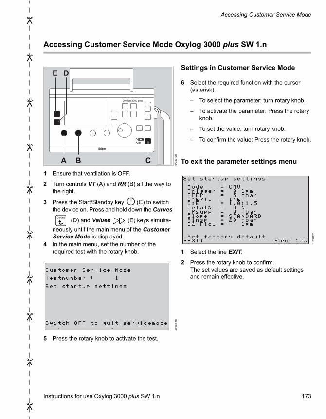
Instructions for use Oxylog 3000 plus SW 1.n 173
Accessing Customer Service Mode
Accessing Customer Service Mode Oxylog 3000 plus SW 1.n
1 Ensure that ventilation is OFF.
2 Turn controls VT (A) and RR (B) all the way to the right.
3 Press the Start/Standby key (C) to switch the device on. Press and hold down the Curves
(D) and Values (E) keys simulta-
neously until the main menu of the Customer Service Mode is displayed.
4 In the main menu, set the number of the required test with the rotary knob.
5 Press the rotary knob to activate the test.
Settings in Customer Service Mode
6 Select the required function with the cursor (asterisk).
– To select the parameter: turn rotary knob.
– To activate the parameter: Press the rotary knob.
– To set the value: turn rotary knob.
– To confirm the value: Press the rotary knob.
To exit the parameter settings menu
1 Select the line EXIT.
2 Press the rotary knob to confirm.The set values are saved as default settings and remain effective.
07
73
71
70
scre
en
18
Oxylog 3000 plus
A B C
DE
Curves
118
37
17
0

174 Instructions for use Oxylog 3000 plus SW 1.n
This page has been left blank intentionally.

Instructions for use Oxylog 3000 plus SW 1.n 175
This page has been left blank intentionally.

These instructions for use only apply to Oxylog 3000 plus SW 1.n.with the Serial No.:If no Serial No. has been filled in by Dräger, these instructions for use are provided for general information only and are not intended for use with any specific machine or device.This document is provided for customer information only, and will not be updated or exchanged without customer request.
Directive 93/42/EECconcerning medical devices
Manufacturer
Drägerwerk AG & Co. KGaAMoislinger Allee 53-5523542 LübeckGermany+49 451 8 82-0
FAX +49 451 8 82-2080http://www.draeger.com
57 05 305 – 5503.420 en© Drägerwerk AG & Co. KGaAEdition: 12 – 2020-01(Edition: 1 – 2009-05)Dräger reserves the right to make modifications to the device without prior notice.