instructions for use vt1000 s - university of florida · instructions for use vt1000 s...
TRANSCRIPT

Instructions for Use
VT1000 SVibrating-blade microtome
Leica VT1000 S, V 2.1 , English - 07/2016Order No. 14 0472 80101 RevIAlways keep this manual with the instrument.Read carefully before working with the instrument.


1Leica VT1000 S - Vibrating-blade microtome
These are determined only by the contract provisions agreed between ourselves and our customers.Leica reserves the right to change technical spec-ifications as well as manufacturing processes without prior notice. Only in this way is it pos-sible to continuously improve the technology and manufacturing techniques used in our products.This document is protected under copyright laws. Any copyrights of this document are retained by Leica Biosystems Nussloch GmbH.Any reproduction of text and illustrations (or of any parts thereof) by means of print, photocopy, microfiche, web cam or other methods – including any electronic systems and media – requires express prior permission in writing by Leica Biosystems Nussloch GmbH.For the instrument serial number and year of manufacture, please refer to the nameplate at the rear side of the instrument.
© Leica Biosystems Nussloch GmbH
The information, numerical data, notes and value judgments contained in this manual represent the current state of scientific knowledge and state-of-the-art technology as we understand it following thorough investigation in this field. We are under no obligation to update the present manual periodically and on an ongoing basis ac-cording to the latest technical developments, nor to provide our customers with additional copies, updates etc. of this manual.To the extent permitted in accordance with the national legal system as applicable in each indi-vidual case, we shall not be held liable for errone-ous statements, drawings, technical illustrations etc. contained in this manual.In particular, no liability whatsoever is accepted for any financial loss or consequential damage caused by or related to compliance with state-ments or other information in this manual.Statements, drawings, illustrations and other information as regards contents or technical details of the present Instructions for Use are not to be considered as warranted characteristics of our products.
Note
Leica Biosystems Nussloch GmbHHeidelberger Str. 17 - 19D-69226 NusslochGermanyPhone: +49 62 24 143-0Fax: +49 6224 143-268 Internet: http://www.LeicaBiosystems.com
Assembly contracted to Leica Microsystems Ltd. Shanghai

2 Instructions for Use, V 2.1 RevI – 07/2016
Contents
1. Important Information ....................................................................................................32. Safety ................................................................................................................................5
2.1 Safety notes ................................................................................................................................... 52.2 Warnings ........................................................................................................................................ 52.3 Safety instructions for handling the instrument ...................................................................... 6
3. Instrument Characteristics ...........................................................................................73.1 Technical Data .............................................................................................................................. 73.2 General overview - VT1000 S ...................................................................................................... 8
4. Installation .....................................................................................................................104.1 Standard delivery ........................................................................................................................ 104.2 Unpacking and setting up the instrument............................................................................... 11
5. Operation ........................................................................................................................135.1 Installation site requirements ................................................................................................... 135.2 Setting up the instrument .......................................................................................................... 145.3 The operating elements and their function - VT1000 S ........................................................ 155.4 Adjusting the amplitude ............................................................................................................. 195.5 Working with the VT1000 S on a daily basis........................................................................... 205.6 Routine daily maintenance and switching off the instrument - VT1000 S ......................... 23
6. Malfunctions: Meaning and Troubleshooting .........................................................247. Cleaning and Maintenance ........................................................................................29
7.1 Cleaning the instrument............................................................................................................. 297.2 Changing the fuse ....................................................................................................................... 30
8. Ordering Information: Spare Parts, Accessory, Consumables .............................318.1 Foot switch ................................................................................................................................... 328.2 Buffer tray .................................................................................................................................... 328.2.1 Double-walled buffer tray S ...................................................................................................... 328.3 Magnifier, fiber optics, cold light source................................................................................ 338.4 Julabo recirculating cooler/chiller FL300 ............................................................................... 34
9. Warranty and Service ..................................................................................................3510. Decontamination Certificate (Master) ......................................................................36

3Leica VT1000 S - Vibrating-blade microtome
Symbols used in this manual and their meaning
1. Important Information
(5)(Fig. 5)
Numbers in parentheses refer to item num-bers in illustrations or to the illustrations themselves.
Useful tips, i.e. important information for the user, appear in gray boxes and are marked by an .
Dangers, warnings and cautions appear in a gray box and are marked by a warning triangle .
Environmental protection symbol of the China RoHS directive. The number in the symbol indicates the "Environment-friendly Use Period" of the product in years.The symbol is used if a substance restricted in China is used in excess of the maximum permitted limit.
The CE labeling shows that the product corresponds to one or more applicable European directives.
Symbol for labeling electrical and elec-tronic equipment in accordance with Section 7 of the German Electrical and Electronic Equipment Act (ElektroG).ElektroG is the law on the bringing into circulation, return and environmentally compatible disposal of electrical and electronic equipment.
Caution! Follow the accompanying documentation!
Instrument model:All information provided in these Instructions for Use applies only to the instrument type indicated on the title page. A nameplate indicating the in-strument serial number is attached to the rear side of the instrument. The figure below is provided as an example only and shows a valid nameplate for this instrument.
Information:When making inquiries, please specify correctly:• Instrument model • Serial number
Observe the Instructions for Use
Order No.
Serial number
Date of Manufacture
Manufacturer
Fig. 1
The Regulatory Compliance Mark (RCM) indicates a device’s compliance with applicable ACMA technical standards of New Zealand and Australia - that is, for telecommunications, radio communica-tions, EMC and EME.
4 Instructions for Use, V 2.1 RevI – 07/2016
Qualification of personnelThe Leica VT1000 S should be operated by trained laboratory personnel only.All laboratory personnel designated to operate this instrument must read these Instructions for Use carefully and must be familiar with all technical features of the instrument before attempt-ing to operate it.
Intended use/improper useThe VT1000 S is used for sectioning in the fields of medicine, biology and industry, and is espe-cially designed for sectioning fixed or unfixed fresh tissue in a buffer solution.
The VT1000 S may be used for research purposes only. Sections made using the VT1000 S must NOT be used for diagnostics!
The instrument must be used exclusively according to the instructions contained in these Instructions for Use.Any other use of the instrument is considered improper.
1. Important Information

5Leica VT1000 S - Vibrating-blade microtome
2. Safety
2.1 Safety notes
These Instructions for Use includes important information related to the operating safety and maintenance of the instrument.The Operating Manual is an important part of the product, and must be read carefully prior to startup and use and must always be kept near the instrument.
This instrument has been built and tested in accordance with the safety requirements for electrical equipment for measurement, control, and laboratory use.
To maintain this condition and ensure safe opera-tion, the user must observe all notes and warnings contained in these Instructions for Use.The current EC Declarations of Conformity can be found on the Internet:
www.LeicaBiosystems.com
2.2 Warnings
The safety devices installed in this instrument by the manufacturer only constitute the basis for accident prevention. Operating the instrument safely is, above all, the responsibility of the owner, as well as the designated personnel who operate, service or clean the instrument.To ensure trouble-free operation of the instrument, make sure to comply with the following instructions and warnings.
These Instructions for Use must be ap-propriately supplemented as required by the existing regulations on accident prevention and environmental safety in the operator‘s country.
The safety and caution notes in this chapter must be observed at all times. Be sure to read these notes even if you are already familiar with the operation and use of other Leica products.
The protective devices located on the instrument and the accessories must not be removed or modified. The instrument must only be opened and repaired by service techni-cians authorized by Leica.

6 Instructions for Use, V 2.1 RevI – 07/2016
2. Safety
2.3 Safety instructions for handling the instrument
Proper handling
Be sure to handle knives and blades very cau-tiously!Never touch the cutting edge of knives and blades!Do not leave knives, blades and bladed knife holders unprotected.
All appropriate safety precautions must be met to avoid the risk of infection.Protective clothing according to safety regula-tions for "Working with harmful substances" (Safety mask, gloves, protective clothing) must be worn!
Cover the magnifier during work breaks as it may act as a burning glass when not covered!
In case of emergency, press the red EMERGENCY STOP switch (at the right side of the instrument). To release the switch, turn it in the direction of the arrow.
The instrument may be opened by authorized service personnel only. Before removing the cover, ensure that the instru-ment is unplugged.
Warning: Avoid touching live parts under any circumstances!
Danger
Caution: Extremely sharp blades pose risk of injury when touched!
Caution: Fresh tissue poses risk of infection!
Caution: When not in use, cover magni-fier with corresponding lid to avoid risk of fire.
7Leica VT1000 S - Vibrating-blade microtome
3. Instrument Characteristics
3.1 Technical Data
General data:
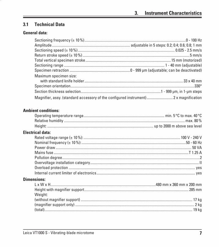
Sectioning frequency (± 10 %) .............................................................................................................0 - 100 Hz Amplitude .................................................................................... adjustable in 5 steps: 0.2; 0.4; 0.6; 0.8; 1 mm Sectioning speed (± 10 %) ........................................................................................................ 0.025 - 2.5 mm/s Return stroke speed (± 10 %) ...................................................................................................................5 mm/s Total vertical specimen stroke ............................................................................................15 mm (motorized) Sectioning range ............................................................................................................ 1 - 40 mm (adjustable) Specimen retraction .................................................................0 - 999 µm (adjustable; can be deactivated) Maximum specimen size: with standard knife holder .......................................................................................................... 33 x 40 mm Specimen orientation .....................................................................................................................................330° Section thickness selection ......................................................................................1 - 999 µm, in 1-µm steps Magnifier, assy. (standard accessory of the configured instrument) ............................ 2 x magnification
Ambient conditions: Operating temperature range ....................................................................................... min. 5 °C to max. 40 °C Relative humidity .................................................................................................................................. max. 80 % Height: .................................................................................................................. up to 2000 m above sea level
Electrical data: Rated voltage range (± 10 %): ........................................................................................................ 100 V - 240 V Nominal frequency (± 10 %): ................................................................................................................50 - 60 Hz Power draw .................................................................................................................................................. 50 VA Mains fuse .................................................................................................................................................T 1.25 A Pollution degree ....................................................................................................................................................2 Overvoltage installation category ..................................................................................................................... II Overload protection ........................................................................................................................................ yes Internal current limiter of electronics .......................................................................................................... yes
Dimensions: L x W x H ...............................................................................................................480 mm x 360 mm x 200 mm Height with magnifier support ................................................................................................................ 285 mm Weight: (without magnifier support) ........................................................................................................................ 17 kg (magnifier support only) ................................................................................................................................ 2 kg (total) ............................................................................................................................................................... 19 kg

8 Instructions for Use, V 2.1 RevI – 07/2016
3. Instrument characteristics
3.2 General overview - VT1000 S
Buffer tray S
EMERGENCY STOP switch (not visible here)
Fixture for magnifier support
Fiber-optic illumination (optional)
Magnifier
Cold light sourceLeica CLS 100 (optional)
Knife holder
Control panel
Magnifier support
Cutting head
Fig. 2

9Leica VT1000 S - Vibrating-blade microtome
Rotary knob for sectioning frequency
LED mode indication: "Totalized section thickness" "Section thickness"
CLR-Clear button
DISP-Programming button Selector button "Single/continuous stroke" (LEDs indicate selected mode)
Toggle switch for knife forward and return stroke
Toggle switch "Buffer tray height adjust-ment" (LEDs indicate limit positions)
Pause button - stops sectioning process
Rotary knob for sectioning
speed
Indication of selected sec-tion thickness or totalized
section thickness in µm
+/- selection button for sec-tion thickness (1 - 999 µm
selectable), retraction and/or volume
Button for setting the limit stops of
the sectioning window
Start button for single / continuous
sectioning stroke
EMERGENCY STOP button
Fixing device for drain tube
Connecting socket for power cord
Power switch
Connection for foot switch, 9-pole
3. Instrument Characteristics
Button for maximum advance speed
Fig. 3
Fig. 4
10 Instructions for Use, V 2.1 RevI – 07/2016
4. Installation
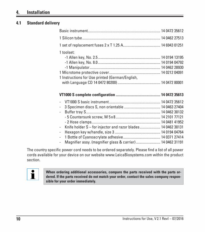
4.1 Standard delivery
Basic instrument .............................................................................. 14 0472 35612
1 Silicon tube .................................................................................... 14 0462 27513
1 set of replacement fuses 2 x T 1.25 A ........................................ 14 6943 01251
1 toolset: -1 Allen key, No. 2.5 ................................................................... 14 0194 13195 -1 Allen key, No. 8.0 ................................................................... 14 0194 04792 -1 Manipulator ............................................................................ 14 0462 28930
1 Microtome protective cover ....................................................... 14 0212 040911 Instructions for Use printed (German/English, with Language CD 14 0472 80200) .............................................. 14 0472 80001
VT1000 S complete configuration ................................................ 14 0472 35613
- VT1000 S basic instrument ....................................................... 14 0472 35612- 3 Specimen discs S, non orientable ....................................... 14 0463 27404- Buffer tray S................................................................................ 14 0462 30132 - 5 Countersunk screw, M 5 x 8 ................................................ 14 2101 77121 - 2 Hose clamps.......................................................................... 14 0481 41952 - Knife holder S – for injector and razor blades ...................... 14 0462 30131- Hexagon key w/handle, size 3 ................................................. 14 0194 04764- 1 Bottle of Cyanoacrylate adhesive ........................................ 14 0371 27414- Magnifier assy. (magnifier glass & carrier) .......................... 14 0462 31191
When ordering additional accessories, compare the parts received with the parts or-dered. If the parts received do not match your order, contact the sales company respon-sible for your order immediately.
The country specific power cord needs to be ordered separately. Please find a list of all power cords available for your device on our website www.LeicaBiosystems.com within the product section.

11Leica VT1000 S - Vibrating-blade microtome
4.2 Unpacking and setting up the instrument
4. Installation
1. Cut through the iron strap (1) and adhesive tape (2) using a suitable tool and remove them.
2. Check the accessory cartons (3) and separate accessories provided (standard scope of delivery - in transparent bag (4) and check to ensure that they are complete.
1
2
3 4
3. Lift the instrument out of the transport carton by the carrying straps (5) and place it on a suitable stable laboratory table. The instrument is securely fastened to the baseplate (6) using a screw.
Tilt the instrument including the baseplate (Fig. 8) - hold the instrument with one hand on the recess (8) for the buffer tray! NEVER lift or hold it by the cutting head (7)! Unscrew the screw (6) using the size 8 Allen key provided and remove the base plate.
5
5
6
7!
8
Fig. 5 Fig. 6
Fig. 7 Fig. 8

12 Instructions for Use, V 2.1 RevI – 07/2016
Fig. 9
5. Using both hands at the sides (Fig. 9), grasp the bottom of the instrument and carefully place it on a suitable laboratory table.
Fig. 10 - Bottom of the instrument2
Assembling the drain tube
• Connect the drain tube (Fig. 10) to the bottom of the instrument (1).• Ensure that the loose end of the drain tube is closed tightly with the
matching stopper.• Secure the loose end of the drain tube in the holder at the rear of the
instrument (2).
1
4
Assembling the magnifier support and foot switch (optional)
Fig. 11
• The magnifier support (3) is packaged separately.• Set it on the instrument as shown in Fig. 11.• Attach the optional foot switch.• Securely plug the foot switch into the 9-pin socket (4).
3
4. Installation
Compare with the attached packing list to make sure the delivery is complete.
When transporting the instrument, always do so WITHOUT the magnifier support!
13Leica VT1000 S - Vibrating-blade microtome
5. Operation
• The instrument is designed for indoor use only.
• The power plug must be freely and easily accessible.
• Power supply at a distance no greater than the length of the power cable (3m) – an extension cable must not be used.
• Level installation location,
• Substrate as free of vibration as possible,
• Relative humidity should not exceed 80 %
• Room temperature consistently between +5 °C and +40 °C
• Avoid vibrations, direct sunlight, and large temperature fluctuations!
The instrument MUST be connected to a grounded power socket. Use only a provided power cable that is intended for the local power supply.
5.1 Installation site requirements
The place of installation must meet the following requirements:
The instrument may not be operated in hazardous locations.

14 Instructions for Use, V 2.1 RevI – 07/2016
2. Make sure the power cable is connected correctly to the instrument.3. Attach the magnifier support.4. Insert the buffer tray.5. Insert the knife holder.6. Insert a blade into the knife holder.7. Connect the magnifier support with optional fiber-optic illumination as shown in Fig. 12. Insert plug (1) of the fiber-optic illumination into socket (2) at the cold light source. 8. Connect the optional foot switch at the rear of the instrument.9. Plug the power cable into the wall socket.10. Switch the instrument on (main switch).
5. Operation
1
2
Fig. 12 Fig. 13
5.2 Setting up the instrument
1. Put the main switch at the back of the instrument to the OFF position.
The instrument MUST be connected to a grounded power socket. Use only a provided power cable that is intended for the local power supply.
The instrument MUST be set up so that the power plug and switch are free and easily accessible at all times!
The Leica VT1000 S is equipped with a autoranging power supply to cover voltages from 100 V to 240 V.After switching on the main switch, the instrument carries out an initial startup run: The blade returns to the rear starting position after a short forward movement.

15Leica VT1000 S - Vibrating-blade microtome
5. Operation
5.3 The operating elements and their function - VT1000 S
Scale setting mm/s 0 0.00 0.5 0.025 1 0.050 2 0.075 3 0.125 4 0.175 5 0.225 6 0.40 7 0.65 8 0.90 9 1.30 10 2.50
10-speed rotating potentiometer with scaleFunction:Continuous knife feed adjustment from 0.05 - 2.5 mm/s:Knife return stroke is performed at constant speed of 5 mm/s. The additional locking lever (lever in 12 o'clock position) prevents the speed setting from be-ing accidentally changed while sectioning is in progress.
SPEED
Rotary knob with scale from 0 to 10
Function:Continuous adjustment of knife sectioning fre-quency (vibration) from 8 - 100 Hz.
Scale setting Hz 0 0 0.5 8 1 10 2 20 3 30 4 40 5 50 6 60 7 70 8 80 9 90 10 100
FREQ
FREQ
Locking lever
SPEED
Caution: Practice working with the controls without a blade holder inserted. Only insert the knife holder when you are completely familiar with all control functions.
Fig. 14
Fig. 15

16 Instructions for Use, V 2.1 RevI – 07/2016
Function:• When the V-Max button is activated in manual mode (LED on - red light)
and the REV/FORW button is pressed, the knife moves towards the speci-men at maximum speed.
• When the START button is pressed, the LED in the V-Max button is extinguished. Sectioning starts at the speed previously selected.
Setting a sectioning window:
5. Operation
2
1Button with LED
Button with LED
If - accidentally - only one limit stop of the sectioning window is set, the knife covers the maximum sectioning range!
• Activate the V-Max button. Press REV/FORW toggle switch for fast move-ment of the blade towards the specimen. Press the button to set the first limit of the sectioning window.
• Press REV/FORW once again, moving the blade edge past the specimen block and press once more to set the second sectioning window limit.
• Press START to deactivate V-Max. The knife edge moves back to the first sectioning window limit and resumes sectioning at the previously selected speed (10-speed rotary potentiometer).
Function:
• Start single or continuous sectioning stroke – according to whether SINGLE or CONT mode has previously been selected (see description of Single/Cont mode for further details).
• Specimen feed (section thickness) takes place prior to each section.• Retraction (specimen is lowered) takes place when the knife reaches
the rear inversive point.• In SINGLE mode, the knife stops automatically in the rear end position.• In CONT mode, START/STOP has to be pressed again to stop the section-
ing movement. The knife stops in the rear end position.• A sectioning process, once started, will continue.
Fig. 16

17Leica VT1000 S - Vibrating-blade microtome
5. Operation
Function:
Immediate interruption of knife movement.• Press PAUSE once again to continue sectioning.
Toggle switch
Function:To move the knife towards the specimen.Can also be used for manual sectioning.Because of safety aspects the FORW movement is carried out only while the toggle switch is pressed and held;the REV movement is carried out completely once the switch has been locked into place.To stop the REV movement before reaching the rear end position, switch the toggle switch manually back into its center position.The REV/FORW switch can also be used to stop a sectioning stroke which has been activated by pressing the START/STOP button.
LED indication with -/+ adjusting button, DISP and CLR function keys
Function of LED indication:Indicates the selected sectioning thickness or totalized section thickness.
Function of the -/+ button:Selection of section thickness in 1-µm steps from 0 to 999 µm.The specimen feed (in the preselected section thickness) takes place at the beginning of each sectioning stroke.
Function of the DISP button:To select between two modes of operation: "∑µm"= section thickness totalizing "µm" = section thickness
Function of the CLR button in section thickness totalizing mode:Sets the value indicated in the section thickness totalizing mode (∑µm) to zero.
Fig. 17
Fig. 18
18 Instructions for Use, V 2.1 RevI – 07/2016
5. Operation
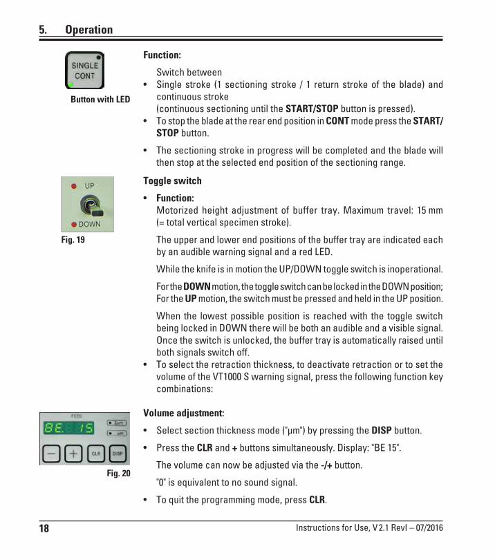
Function:
Switch between • Single stroke (1 sectioning stroke / 1 return stroke of the blade) and
continuous stroke (continuous sectioning until the START/STOP button is pressed).• To stop the blade at the rear end position in CONT mode press the START/
STOP button.
• The sectioning stroke in progress will be completed and the blade will then stop at the selected end position of the sectioning range.
Toggle switch
• Function: Motorized height adjustment of buffer tray. Maximum travel: 15 mm
(= total vertical specimen stroke).
The upper and lower end positions of the buffer tray are indicated each by an audible warning signal and a red LED.
While the knife is in motion the UP/DOWN toggle switch is inoperational.
For the DOWN motion, the toggle switch can be locked in the DOWN position; For the UP motion, the switch must be pressed and held in the UP position.
When the lowest possible position is reached with the toggle switch being locked in DOWN there will be both an audible and a visible signal. Once the switch is unlocked, the buffer tray is automatically raised until both signals switch off.
• To select the retraction thickness, to deactivate retraction or to set the volume of the VT1000 S warning signal, press the following function key combinations:
Volume adjustment:
• Select section thickness mode ("µm") by pressing the DISP button.
• Press the CLR and + buttons simultaneously. Display: "BE 15".
The volume can now be adjusted via the -/+ button.
"0" is equivalent to no sound signal.
• To quit the programming mode, press CLR.
Button with LED
Fig. 19
Fig. 20

19Leica VT1000 S - Vibrating-blade microtome
Adjusting the retraction
• In programming mode, press DISP to display the specimen retraction menu.
• Display: "LO".
• Set specimen retraction between 1 and 999 µm via the -/+ button; or dis-able by selecting "0".
• The selected value will be displayed in the FEED window.
• Press CLR to quit the menu function.
5.4 Adjusting the amplitude
• To obtain excellent sectioning results, the amplitude requires adjustment according to the specimen type being sectioned.
5. Operation
1
Fig. 21
When adjusting the amplitude setting, do not remove the clamping screw, simply loosen it.The instrument is shipped with the amplitude set to 0.6 mm.
To this end:
• With a No. 2.5 Allen key loosen the clamping screw (1) and secure the eccentric on the bottom with your finger.
Selectable amplitude positions are, from left to right: 0.2 mm; 0.4 mm; 0.6 mm; 0.8 mm; 1 mm.• Slide the amplitude clamping screw to the desired amplitude position
and retighten.
Fig. 22
20 Instructions for Use, V 2.1 RevI – 07/2016
5. Operation
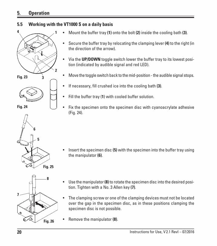
5.5 Working with the VT1000 S on a daily basis
• Mount the buffer tray (1) onto the bolt (2) inside the cooling bath (3).
• Secure the buffer tray by relocating the clamping lever (4) to the right (in the direction of the arrow).
• Via the UP/DOWN toggle switch lower the buffer tray to its lowest posi-tion (indicated by audible signal and red LED).
• Move the toggle switch back to the mid-position - the audible signal stops.
• If necessary, fill crushed ice into the cooling bath (3).
• Fill the buffer tray (1) with cooled buffer solution.
• Fix the specimen onto the specimen disc with cyanoacrylate adhesive (Fig. 24).
• Insert the specimen disc (5) with the specimen into the buffer tray using the manipulator (6).
• Use the manipulator (8) to rotate the specimen disc into the desired posi-tion. Tighten with a No. 3 Allen key (7).
• The clamping screw or one of the clamping devices must not be located over the gap in the specimen disc, as in these positions clamping the specimen disc is not possible.
• Remove the manipulator (8).
1
2
3
4
5
6
7
8
Fig. 23
Fig. 24
Fig. 25
Fig. 26
21Leica VT1000 S - Vibrating-blade microtome
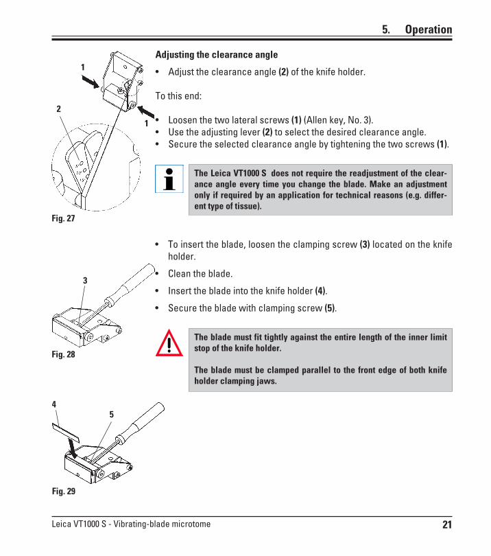
Adjusting the clearance angle
• Adjust the clearance angle (2) of the knife holder.
To this end:
• Loosen the two lateral screws (1) (Allen key, No. 3).• Use the adjusting lever (2) to select the desired clearance angle.• Secure the selected clearance angle by tightening the two screws (1).
5. Operation
1
1
2
3
54
The blade must fit tightly against the entire length of the inner limit stop of the knife holder.
The blade must be clamped parallel to the front edge of both knife holder clamping jaws.
The Leica VT1000 S does not require the readjustment of the clear-ance angle every time you change the blade. Make an adjustment only if required by an application for technical reasons (e.g. differ-ent type of tissue).
• To insert the blade, loosen the clamping screw (3) located on the knife holder.
• Clean the blade.
• Insert the blade into the knife holder (4).
• Secure the blade with clamping screw (5).
Fig. 27
Fig. 28
Fig. 29

22 Instructions for Use, V 2.1 RevI – 07/2016
• Fix the knife holder (1) with the knife holder clamping screw (2).
• Use the REV/FORW rocker button to place the blade edge right behind the rear edge (from user's view) of the specimen.
• Pull the UP/DOWN rocker button into the UP direction and keep it in the UP position until the specimen surface is shortly below the level of the blade edge (see arrow (3, Fig. 31)).
• Select sectioning speed and sectioning frequency with the rotary knobs SPEED and FREQ.
• Use the +/- button to select a sectioning thickness for trimming.
• Select a sectioning range appropriate to the size of the specimen with the SECTIONING WINDOW button.
• Switch the SINGLE/CONT button to CONT.
Push the START/STOP button.
The instrument will now trim the specimen at the selected trimming thickness until you push the START/STOP button once more.
• Once you have reached the desired specimen plane for sectioning, use the +/- button to select the desired thickness for sectioning.
For sectioning proceed as follows:
• Select the desired section thickness via the +/- button.
• Switch the SINGLE/CONT button to SINGLE.
• Push the START/STOP button.
The instrument will now produce a section (4). When the section is fin-ished, the knife will automatically stop at the rear end position behind the specimen (from the user's view).
• Pick up the section as shown on the left using a brush (5) to mount it on a glass slide (6).
5. Operation
1
2
3
4
56
Fig. 30
Fig. 31
Fig. 32
23Leica VT1000 S - Vibrating-blade microtome
5.6 Routine daily maintenance and switching off the instrument - VT1000 S
After all daily procedures have been finished, perform the following:
• Switch off the main switch at the back of the instrument.
• Place the magnifier cover on the magnifier.
• Remove the knife holder.
• Take the blade out of the knife holder and dispose it properly and safely.
• Remove the specimen disc and lay it flat on the stage.
• Remove the specimen using a single-edge blade. Then, remove remains of cyanoacrylate adhesive from the specimen disc.
• Remove and empty out the buffer tray. Dispose of the contents of the buffer tray properly.
• Drain the cooling bath. To do so, release the tube from its holder at the rear of the instrument
and dispose of the contents of the ice bath into a suitable vessel. Then wipe off with a dry cloth.
5. Operation
Caution! The contents of the ice bath can become contaminated if buffer solution is spilled over it.

24 Instructions for Use, V 2.1 RevI – 07/2016
6. Malfunctions: Meaning and Troubleshooting
Error messages/symptoms Sources of error Troubleshooting
- Collision of knife and specimen disc.
- Clearance angle adjustment:- If a clearance angle wider than
5° is selected, specimen disc and knife edge can potentially collide with each other.
- Lower the specimen disc suf-ficiently to prevent collision.
- When working with directional specimen holders, knife edge and specimen holder can col-lide at any selected clearance angle.
- Lower the specimen disc suf-ficiently to prevent collision.
When working with direction-al specimen discs, move the buffer tray to its lowest posi-tion directly after switching on the instrument!
- Audible warning signal.- Return stroke is not completed.
- Operating error due to locking function of the REV/FORW button:
- With the REV/FORW button locked the instrument is switched off via the power switch at the rear of the instru-ment and is switched on again without releasing the REV/FORW button to its center posi-tion.
Unlock the REV/FORW button by pulling it back to the center position.
- To reactivate the return stroke movement, lock the REV/FORW button again (to REV position).
- Audible warning signal.- Return stroke is not completed.
- With the REV/FORW button locked, the instrument was switched off via the emergency stop and after that, the emer-gency stop was released again without releasing the REV/FORW button to its center posi-tion.
- With the REV/FORW button locked, the instrument was switched off via the emergency stop and after that, the emer-gency stop was released again without releasing the REV/FORW button to its center posi-tion.

25Leica VT1000 S - Vibrating-blade microtome
6. Malfunctions: Meaning and Troubleshooting
Error messages/symptoms Sources of error Troubleshooting
- Audible warning signal.- Downward stroke is not com-
pleted.
- Operating error due to locking function of the UP/DOWN button:
- With the UP/DOWN button locked in the DOWN position the instrument was switched off via the power switch at the rear of the instrument switched on again without releasing the UP/DOWN button to its center posi-tion.
- Release the UP/DOWN button to its center position.
- To reactivate the downward motion, activate the UP/DOWN button again (DOWN).
- Audible warning signal.- Downward stroke is not com-
pleted.
- With the UP/DOWN button locked the instrument was switched off via the EMERGEN-CY STOP (foot switch or Emer-gency stop button) and after that the EMERGENCY STOP was released without unlocking the UP/DOWN button.
- Release the UP/DOWN button to its center position.
- To reactivate the downward motion, activate the UP/DOWN button again (DOWN).
- The feed motor stops.- Any processing step (sectioning
stroke etc.) is interrupted imme-diately.
- Any UP/DOWN motion of the buffer tray is interrupted imme-diately.
- Any locked buttons are indicat-ed by an audible warning signal.
- When pressing any key, the instrument gives an audible warning signal.
- In case the EMERGENCY STOP function has been activated, the instrument will remain inopera-tional when pressing the foot switch.
- The indication SP is displayed.
- The EMERGENCY STOP function has been activated.
- Release the Emergency stop button.
- Select an operating mode and continue working.

26 Instructions for Use, V 2.1 RevI – 07/2016
6. Malfunctions: Meaning and Troubleshooting
Error messages/symptoms Sources of error Troubleshooting
- Audible warning signal.- Error code E0.1xx is displayed.
xx - there are several error codes, 00 - there is only one error code.
- Button(s) jammed or defective.- Locking function /REV or REV/
FORW button defective.
- Error on the UP/DOWN button; DOWN locking function.
- Push the button several times to unlock;
have defective button replaced by the Technical Service.
Error code E0.200 is displayed. - Feed mechanism defective. - Switch off the instrument; call the Technical Service.
- Error code E0.300 is displayed. - Important electronic component defective.
- Switch off the instrument; call the Technical Service.
- Error code E0.400 is displayed. - Feed motor defective. - Switch off the instrument; call the Technical Service.
Error code E.05xx is displayed. - Light barrier error (forward feed)
- Switch off the instrument; call the Technical Service.
- Audible warning signal.- Error code E0.600 is displayed.
- Light barrier error (section thickness feed)
- Switch off the instrument; call the Technical Service.
- Audible warning signal.- Error code E0.700 is displayed.
for approx. 2 secs.
- Software detected severe hard-ware fault.
- Switch off the instrument; call the Technical Service.

27Leica VT1000 S - Vibrating-blade microtome
6. Malfunctions: Meaning and Troubleshooting
Error messages/symptoms Sources of error Troubleshooting
- Audible warning signal.- Error code E0.9xx is displayed.
- STM32 Watch dog reset. - Instrument can be used as nor-mal after restart.
- In case of further problems, call the Technical Service.
- Audible warning signal.- Optical signal via red LED.
- The upper limit of the specimen feed has been reached.
- Leave the upper limit position (Switch the UP/DOWN button in DOWN direction).
- Mount a new specimen onto the specimen holder and start again.
- Audible warning signal.- Optical signal via red LED.
- The lower limit of the specimen level has been reached (height adjustment of specimen via buf-fer tray).
- After unlocking the DOWN posi-tion the buffer tray is automati-cally raised until the audible and optical signals turn off.
- Audible warning signal. - User has tried to select a speci-men thickness via the "+/-" but-ton that is below the minimum value (0 µ m ) or above the maxi-mum value (999 µm).
- Release the "+/-" button.
- Audible warning signal. (When operating the instrument
for the first time or after the E-EPROM has been exchanged.)
- The warning signal will cease automatically after the initializa-tion phase.

28 Instructions for Use, V 2.1 RevI – 07/2016
6. Malfunctions: Meaning and Troubleshooting
Error messages/symptoms Sources of error Troubleshooting
- A clattering sound can be heard. - The visible clamping screws have become loose during sec-tioning.
These symptoms may occur from time to time and are un-avoidable, as the clamping screws which have to be op-erated by the user cannot be sealed.
- Retighten the loose clamping screws.
If the clattering sound does not cease once the clamping screws have been retight-ened, do not hesitate to call the Technical Service imme-diately.Do not use the instrument when in this condition.

29Leica VT1000 S - Vibrating-blade microtome
Cleaning the knife
When cleaning the knife/blade, always wipe from the knife or blade back towards the cutting edge, NEVER wipe in the opposite direction - risk of injury!
Clean using an alcohol-based solution or acetone.
7. Cleaning and Maintenance
Before each cleaning, carry out the following preparatory steps:
• Switch off the instrument and disconnect the power plug.• Remove the blade from the knife holder and insert it in the receptacle at the bottom of the
blade dispenser.• Remove the knife holder for cleaning.• Remove the specimen plate from the buffer tray and lay it flat on the stage. Carefully remove
the specimen with a single-edge blade. • Remove section waste using tweezers or a brush.• Remove the buffer tray, empty it and rinse it separately with water (refer also to Chap. 5.6.)
7.1 Cleaning the instrument
Instrument and outside surfaces
If necessary, the varnished outside surfaces of the control panels can be cleaned with a mild commercial household cleaner or soap water and then be wiped with a cloth.The instrument must be completely dry before it can be used again.
Always remove the knife / blade before detaching the knife holder from the instrument.Always put the knife (blade) back into the knife case or blade dispenser when not in use!When using cleaners, comply with the safety instructions from the manufacturer and the labor-safety regulations at your laboratory.When cleaning the outer surfaces, do not use xylene or solvents containing acetone or xylene. The finished surfaces are not resistant to xylene or acetone! Ensure that liquids do not enter the interior of the instrument during cleaning.

30 Instructions for Use, V 2.1 RevI – 07/2016
7. Cleaning and maintenance
7.2 Changing the fuse
If the instrument fails completely, first check the power supply at the power socket. Then check the fuses at the rear side of the instrument.
To do so, proceed as follows:• Using a screwdriver (13), carefully push out
the fuse insert (14) (Fig. 33 - top).• Remove the fuse insert - it contains two fuses
(15).
• Check that the thin wire (16) in the glass capil-lary of a fuse is intact. If not, replace the fuse (the standard scope of delivery includes two replacement fuses).
• Insert the fuse insert with the two fuses and start up the instrument again.
14
15
13
14
16
Before changing a fuse, always switch off the instrument first and remove the instrument cable completely. The instrument must have cooled down and the paraffin tank must be empty.When changing a fuse, do NOT use any fuses other than the spare fuses supplied with the instru-ment.
Fig. 33
Before plugging the power cable back in and switching on the instrument, you must have identified and corrected the cause of the burned-out fuse.

31Leica VT1000 S - Vibrating-blade microtome
8. Ordering Information: Spare Parts, Accessory, Consumables
Knife holder S ................................................................................... 14 0462 30131Buffer tray S ..................................................................................... 14 0462 30132Buffer tray S, double-walled .......................................................... 14 0463 46423Specimen disc S, Ø 50 mm, non-directional* ............................. 14 0463 27404Magnetic specimen holder, directional ....................................... 14 0462 32060Foot switch with protective housing ............................................ 14 0463 27415Magnifier, complete ........................................................................ 14 0462 31191Fiber-optic light guide .................................................................... 14 0502 30028Cold light sources Leica CLS100X 100-120 V/50-60 Hz ......................................... 14 0502 30214 Leica CLS100X 230-240 V/50-60 Hz ......................................... 14 0502 30215 Leica CLS100X 240 V/50-60 Hz .......................................... 14 0502 30216Sapphire knife .................................................................................. 14 0216 39372Cyanoacrylate glue ......................................................................... 14 0371 27414Julabo FL300, recirculating cooler/chiller100 V/50/60 Hz ................................................................................... 14 0481 48439115 V/50 Hz ........................................................................................ 14 0481 48437230 V/50-60 Hz .................................................................................. 14 0481 48436230 V/60 Hz ........................................................................................ 14 0481 48438Antifrogen N ..................................................................................... 14 0481 45443

32 Instructions for Use, V 2.1 RevI – 07/2016
8. Ordering Information: Spare Parts, Accessory, Consumables
8.1 Foot switch
Foot switch• The foot switch is an optional accessory which can be used instead of the START/STOP button.
Order No. .....................14 0463 27415
8.2 Buffer tray
8.2.1 Double-walled buffer tray S
Order No. .......................................14 0463 46423
A clamp for holding the gassing hose for the buffer in the proper position can be added to the double-walled buffer tray.First connect the hoses (2, included in the stan-dard delivery of the double-walled buffer tray) to the rear of the Julabo Recirculating Cooler/Chiller FL300, then connect the other end to the empty buffer tray. Access is easier if you make the left connection first. To do so, pull back the lock coupling, attach the hose, and release the coupling until you hear it click into position. • Hose set for connecting a recirculating
cooler/chiller included.
Fig. 35
11 11
2
Fig. 34
When using the double-walled buffer tray, the flow cooler must be installed according to the assembly instructions prior to working with specimens.
Fig. 36

33Leica VT1000 S - Vibrating-blade microtome
8. Ordering Information: Spare Parts, Accessory, Consumables
8.3 Magnifier, fiber optics, cold light source
Fiber-optic illumination• To be mounted onto the magnifier after the
magnifier has been mounted into the fixture. Then, connect the fiber optics to the cold light source.
Order No. ..................................... 14 0502 30028
Magnifier• To be inserted into the fixture.
Order No. ..................................... 14 0462 31191
Leica CLS 100 cold light source• Serves as a light source for the fiber-optic
illumination.
100-120 V, 50/60 Hz, Order No. 14 0502 30214 230 V, 50/60 Hz, Order No. 14 0502 30215 240 V, 50/60 Hz, Order No. 14 0502 30216
Fig. 37
Fig. 38

34 Instructions for Use, V 2.1 RevI – 07/2016
8. Ordering information: Spare Parts, Accessory, Consumables
Recirculating cooler/chiller for connection to the double-walled buffer tray in the Leica VT1000 S and VT1200/VT1200 S.Selectable temperature range: –20 °C to +40 °C. Recommended cooling medium: Antifrogen N (14 0481 45443) Mixture with water (50 %/50 %) Application example:If (at an ambient temperature of 20 - 22 °C) a temperature of 4 °C is to be reached in the buffer trough, the setting value of 0.5 - 2 °C must be selected.
8.4 Julabo recirculating cooler/chiller FL300
Fig. 39
For additional information, refer to the Instructions for Use provided with this instrument.

35Leica VT1000 S - Vibrating-blade microtome
Warranty
Leica Biosystems Nussloch GmbH guarantees that the contractual product delivered has been subjected to a comprehensive quality control proce-dure based on the Leica in-house testing standards, and that the product is faultless and complies with all technical specifications and/or agreed characteristics warranted.The scope of the warranty is based on the content of the concluded agree-ment. The warranty terms of your Leica sales organization or the organiza-tion from which you have purchased the contractual product shall apply exclusively.
Service information
If you are in need of technical customer support or spare parts, please contact your Leica representative or the Leica dealer where you purchased the instrument.Please provide the following information:
• Model name and serial number of the instrument• Location of the instrument and name of the person to contact• Reason for the service call• Delivery date
Decommissioning and disposal
The instrument or parts of the instrument must be disposed of according to existing applicable, local regulations.
9. Warranty and Service

36 Instructions for Use, V 2.1 RevI – 07/2016
10. Decontamination Certificate (Master)
Leica Biosystems Nussloch GmbHHeidelberger Str. 17-1969226 Nussloch, Germany
Phone: ++49 (0) 6224 143 0Fax: ++49 (0) 6224 143 268www.LeicaBiosystems.com
Tick Box A if applicable. Otherwise please complete all parts of B, providing further information as requested or appropriate.
Decontamination Certificate
Nameplate information Model (see nameplate)* SN (see nameplate)*
REF (see nameplate)*
This equipment has not been in contact with unfixed biological samples.AB
This equipment has been exposed internally or externally to hazardous materials as indicated below:
Yes NoBlood, body fluids, pathological samples
Other biohazards
Chemicals/substances hazardous to health
Other hazards
Yes
This equipment has been cleaned and decontaminated:Yes No
If yes, give details of the method:
If no**, please indicate why not:
Please provide further detail here:
Please provide further detail here:
** Such equipment must not be returned without the written agreement of Leica Biosystems.
The equipment has been prepared to ensure safe handling/transportation.Whenever possible, please use the original transportation case/box.
Yes No
1
3
2
Signature/Date*
Name*
Position*
Institute*
Department*
Address*
Phone* Fax
Important - to avoid refusal of shipment:Place one copy in the unit prior to packaging, or hand it over to the service engineer. Customer assumes all responsibility for the immediate return shipment of articles sent to Leica without proper decontamination documentation. If you have any further questions, please call your local Leica organization.Leica Internal Use: If applicable, note corresponding Job and RAN-/RGA-Number:
Job Sheet No.: _______________ BU Return Authorization Number: ______________ SU Return Goods Authorization: ______________
Vers
ion
3.5
- 01/
2013
, Ord
er-N
o. 1
4 07
00 8
3101
Dear Customer,Any product that is to be returned to Leica Biosystems or serviced on site, must be cleaned and decontaminated in the appropriate manner. Since it is not possible to decontaminate for prion diseases, such as CJD, BSE, CWD etc., equipment exposed to specimens containing prion diseases cannot be returned to Leica Biosystems for repair. On-site repair of prion contaminated equipment will only be conducted after the Field Service Engineer has been educated in the risks, instructed in the policies and procedures of the institution, and provided with personal protective equipment. Please fill out this confirmation carefully and enclose a copy with the instrument. Attach the confirmation to the outside of the flight case or hand it directly to the service technician.Packages will not be opened, nor servicing commenced until the Company or service engineer have received a satisfactory certificate. Should returned goods be considered a hazard by the Company, they will be returned immediately to the customer at his/her expense. Note: Microtome knives must be in boxes. Mandatory information: Fields marked with * are mandatory. Depending on whether the instrument is contaminated, please also complete either section A or section B.
Radioactivity

37Leica VT1000 S - Vibrating-blade microtome
10. Decontamination Certificate (Master)
Leica Biosystems Nussloch GmbHHeidelberger Str. 17-1969226 Nussloch, Germany
Phone: ++49 (0) 6224 143 0Fax: ++49 (0) 6224 143 268www.LeicaBiosystems.com
Tick Box A if applicable. Otherwise please complete all parts of B, providing further information as requested or appropriate.
Decontamination Certificate
Nameplate information Model (see nameplate)* SN (see nameplate)*
REF (see nameplate)*
This equipment has not been in contact with unfixed biological samples.AB
This equipment has been exposed internally or externally to hazardous materials as indicated below:
Yes NoBlood, body fluids, pathological samples
Other biohazards
Chemicals/substances hazardous to health
Other hazards
Yes
This equipment has been cleaned and decontaminated:Yes No
If yes, give details of the method:
If no**, please indicate why not:
Please provide further detail here:
Please provide further detail here:
** Such equipment must not be returned without the written agreement of Leica Biosystems.
The equipment has been prepared to ensure safe handling/transportation.Whenever possible, please use the original transportation case/box.
Yes No
1
3
2
Signature/Date*
Name*
Position*
Institute*
Department*
Address*
Phone* Fax
Important - to avoid refusal of shipment:Place one copy in the unit prior to packaging, or hand it over to the service engineer. Customer assumes all responsibility for the immediate return shipment of articles sent to Leica without proper decontamination documentation. If you have any further questions, please call your local Leica organization.Leica Internal Use: If applicable, note corresponding Job and RAN-/RGA-Number:
Job Sheet No.: _______________ BU Return Authorization Number: ______________ SU Return Goods Authorization: ______________
Vers
ion
3.5
- 01/
2013
, Ord
er-N
o. 1
4 07
00 8
3101
Dear Customer,Any product that is to be returned to Leica Biosystems or serviced on site, must be cleaned and decontaminated in the appropriate manner. Since it is not possible to decontaminate for prion diseases, such as CJD, BSE, CWD etc., equipment exposed to specimens containing prion diseases cannot be returned to Leica Biosystems for repair. On-site repair of prion contaminated equipment will only be conducted after the Field Service Engineer has been educated in the risks, instructed in the policies and procedures of the institution, and provided with personal protective equipment. Please fill out this confirmation carefully and enclose a copy with the instrument. Attach the confirmation to the outside of the flight case or hand it directly to the service technician.Packages will not be opened, nor servicing commenced until the Company or service engineer have received a satisfactory certificate. Should returned goods be considered a hazard by the Company, they will be returned immediately to the customer at his/her expense. Note: Microtome knives must be in boxes. Mandatory information: Fields marked with * are mandatory. Depending on whether the instrument is contaminated, please also complete either section A or section B.
Radioactivity

38 Instructions for Use, V 2.1 RevI – 07/2016
Notes


www.LeicaBiosystems.com
Leica Biosystems Nussloch GmbHHeidelberger Straße 17-19D- 69226 NusslochPhone: +49 - (0) 6224 - 143 0Fax: +49 - (0) 6224 - 143 268Web: www.LeicaBiosystems.com