instructions-parts list 308852 - graco inc.€¦ · displacement pump 308815. . . . . . . . . . . ....
TRANSCRIPT

308852Rev. F
First choice whenquality counts.�
7727B7728A
Model 232135Model 232138
Related ManualsDisplacement Pump 308815. . . . . . . . . . . . . . . . . Fluid Filter 308249. . . . . . . . . . . . . . . . . . . . . . . . . . Spray Gun 307614. . . . . . . . . . . . . . . . . . . . . . . . . Spray Tip 308644. . . . . . . . . . . . . . . . . . . . . . . . . . .
Model 232137 Model 232136
Model 232138Model 232135
Model 232139
Model 232139
Model 232134
Model 232134
INSTRUCTIONS-PARTS LIST
INSTRUCTIONS
This manual contains importantwarnings and information.READ AND KEEP FOR REFERENCE.
ULTRA� MAX 695Airless Paint Sprayer3000 psi (210 bar, 21 MPa) Maximum Working Pressure
230 VACModel 232138, Series AComplete Hi-boy sprayer with hoses, gun, RAC IV� DripLess�Tip Guard and SwitchTip�
240 VACModel 232134, Series AComplete Hi-boy sprayer with hoses, gun, RAC IV� DripLess�Tip Guard and SwitchTip�
Model 232135, Series AComplete Lo-boy sprayer with hoses, gun, RAC IV� DripLess�Tip Guard and SwitchTip�
120 VACModel 232139, Series AComplete Hi-boy sprayer with hoses, gun, RAC IV� DripLess�Tip Guard and SwitchTip�
100 VACModel 232136, Series ABasic Hi-boy sprayer
Model 232137, Series ABasic Lo-boy sprayer
Table of ContentsComponent Function and Identification 2. . . . . . . . . . . . Grounding 3. . . . . . . . . . . . . . . . . . . . . . . . . . . . . . . . . . . . . General Repair Information 3. . . . . . . . . . . . . . . . . . . . . . Troubleshooting 4. . . . . . . . . . . . . . . . . . . . . . . . . . . . . . . . Motor Test 9. . . . . . . . . . . . . . . . . . . . . . . . . . . . . . . . . . . . . Motor Brushes 10. . . . . . . . . . . . . . . . . . . . . . . . . . . . . . . . Displacement Pump 11. . . . . . . . . . . . . . . . . . . . . . . . . . . Motor 12. . . . . . . . . . . . . . . . . . . . . . . . . . . . . . . . . . . . . . . . Motor Control Board 14. . . . . . . . . . . . . . . . . . . . . . . . . . . Power Cord 14. . . . . . . . . . . . . . . . . . . . . . . . . . . . . . . . . . . On/Off Switch 14. . . . . . . . . . . . . . . . . . . . . . . . . . . . . . . . . Pressure Adjusting Potentiometer 14. . . . . . . . . . . . . . .
Drive Housing, Connecting Rod, Crankshaft 15. . . . . . Pressure Transducer 16. . . . . . . . . . . . . . . . . . . . . . . . . . . Pressure Transducer Seal 16. . . . . . . . . . . . . . . . . . . . . . Suction Hose 17. . . . . . . . . . . . . . . . . . . . . . . . . . . . . . . . . Drain Valve 18. . . . . . . . . . . . . . . . . . . . . . . . . . . . . . . . . . . Technical Data 19. . . . . . . . . . . . . . . . . . . . . . . . . . . . . . . . Dimensions 19. . . . . . . . . . . . . . . . . . . . . . . . . . . . . . . . . . . Accessories 19. . . . . . . . . . . . . . . . . . . . . . . . . . . . . . . . . . Complete Sprayer Parts 20. . . . . . . . . . . . . . . . . . . . . . . . Graco Warranty 24. . . . . . . . . . . . . . . . . . . . . . . . . . . . . . . Phone Number 24. . . . . . . . . . . . . . . . . . . . . . . . . . . . . . . .
GRACO INC. P.O. BOX 1441 MINNEAPOLIS, MN 55440–1441Graco Inc. is registered to I.S. EN ISO 9001

�� ������
Component Function and Identification
7727B
�����
C
Fig. 1
E
F
DA
G
J
L
R
M
N
B
H
S
K P
Models 232138, 232136, 232139 and 232134
A Motor (Under shield shown) DC motor, permanent magnet, totally enclosed, fan cooled
B Pressure Adjusting Knob Controls fluid outlet pressure
C ON/OFF Switch Power switch that controls VAC main power to sprayer
D Drive Assembly Transfers power from DC motor to the displacement pump
E Fluid Filter Filter of fluid between source and spray gun
F Fluid Outlet Main hose to spray gun is connected here
G Pail Hanger Container for fluid to be sprayed may be hung here
H Displacement Pump Transfers fluid to be sprayed from source through spray gun
J 50 ft (15 m) Main Hose 1/4 in. ID, grounded, nylon hose with spring guards on both ends
K RAC IV Tip Guard Reverse-A-Clean (RAC) tip guard reduces the risk of fluid injection injury
L Contractor Gun High pressure spray gun with gun safety latch
M RAC IV Switch Tip RAC switch tip uses high pressure fluid to remove clogs from spray tipwithout removing tip from spray gun
N 3 ft (0.9 m) Hose 3/16 in. ID, grounded, nylon hose used between 50 ft hose and spray gunto allow more flexibility when spraying
P Pressure Drain Valve Relieves fluid outlet pressure when open; diverts fluid to drain line
R Pressure Control Controls motor speed to maintain fluid outlet pressure at displacementpump outlet. Works with pressure adjusting knob.
S Spray Gun Safety Latch Inhibits accidental triggering of spray gun
������ ��
General Repair Information
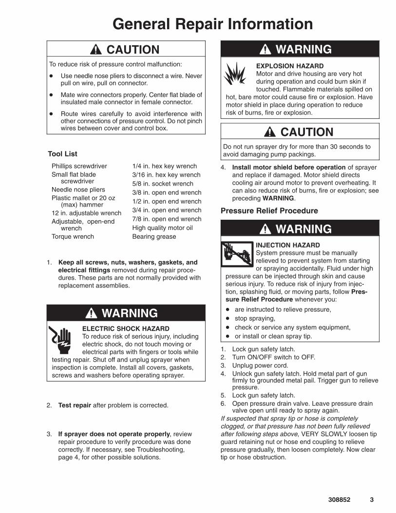
CAUTIONTo reduce risk of pressure control malfunction:
� Use needle nose pliers to disconnect a wire. Neverpull on wire, pull on connector.
� Mate wire connectors properly. Center flat blade ofinsulated male connector in female connector.
� Route wires carefully to avoid interference withother connections of pressure control. Do not pinchwires between cover and control box.
Phillips screwdriverSmall flat blade
screwdriverNeedle nose pliersPlastic mallet or 20 oz
(max) hammer12 in. adjustable wrenchAdjustable, open-end
wrenchTorque wrench
1/4 in. hex key wrench3/16 in. hex key wrench5/8 in. socket wrench3/8 in. open end wrench1/2 in. open end wrench3/4 in. open end wrench7/8 in. open end wrenchHigh quality motor oilBearing grease
Tool List
1. Keep all screws, nuts, washers, gaskets, andelectrical fittings removed during repair proce-dures. These parts are not normally provided withreplacement assemblies.
WARNINGELECTRIC SHOCK HAZARDTo reduce risk of serious injury, includingelectric shock, do not touch moving orelectrical parts with fingers or tools while
testing repair. Shut off and unplug sprayer wheninspection is complete. Install all covers, gaskets,screws and washers before operating sprayer.
2. Test repair after problem is corrected.
3. If sprayer does not operate properly, reviewrepair procedure to verify procedure was donecorrectly. If necessary, see Troubleshooting, page 4, for other possible solutions.
WARNINGEXPLOSION HAZARDMotor and drive housing are very hotduring operation and could burn skin iftouched. Flammable materials spilled on
hot, bare motor could cause fire or explosion. Havemotor shield in place during operation to reducerisk of burns, fire or explosion.
CAUTIONDo not run sprayer dry for more than 30 seconds toavoid damaging pump packings.
4. Install motor shield before operation of sprayerand replace if damaged. Motor shield directscooling air around motor to prevent overheating. Itcan also reduce risk of burns, fire or explosion; seepreceding WARNING.
Pressure Relief Procedure
WARNINGINJECTION HAZARDSystem pressure must be manuallyrelieved to prevent system from startingor spraying accidentally. Fluid under high
pressure can be injected through skin and causeserious injury. To reduce risk of injury from injec-tion, splashing fluid, or moving parts, follow Pres-sure Relief Procedure whenever you:
� are instructed to relieve pressure,� stop spraying,� check or service any system equipment,� or install or clean spray tip.
1. Lock gun safety latch.2. Turn ON/OFF switch to OFF.3. Unplug power cord.4. Unlock gun safety latch. Hold metal part of gun
firmly to grounded metal pail. Trigger gun to relievepressure.
5. Lock gun safety latch.6. Open pressure drain valve. Leave pressure drain
valve open until ready to spray again.If suspected that spray tip or hose is completelyclogged, or that pressure has not been fully relievedafter following steps above, VERY SLOWLY loosen tipguard retaining nut or hose end coupling to relievepressure gradually, then loosen completely. Now cleartip or hose obstruction.

�� ������
Grounding
WARNINGImproper installation or alteration of grounding plugresults in risk of electric shock, fire or explosionthat could cause serious injury or death.
1. Models 232138, 232135, 232134 require a 230VAC, 50 Hz, 10A circuit with a grounding recep-tacle. Model 232139 requires a 120 VAC, 50/60Hz, 15A circuit with a grounding receptacle. Mod-els 232136, 232137 require a 100 VAC, 50 Hz,15A circuit with a grounding receptacle. See Fig. 2.
2. Do not alter ground prong or use adapter.
Fig. 2
Grounding Plug GroundedOutlets
230 VAC plug and outlet 9248A
3. A 12 AWG, 3 wires with grounding prong, 300 ft(90 m) extension cord may be used. Long lengthsreduce sprayer performance.
Troubleshooting
Relieve pressure; page 3.
Basic Problem SolvingTYPE OF PROBLEM
WHAT TO CHECKIf check is OK, go to next check
WHAT TO DOWhen check is not OK, refer to this column
Fluid Pressure 1. Pressure control knob setting. Motor will not run if at mini-mum setting (fully counterclockwise).
1. Slowly increase pressure setting to see ifmotor starts.
2. Clogged spray tip or fluid filter, if used. Refer to separategun, tip or fluid filter instruction manual.
2. If tip is still clogged, relieve pressure;refer to separate gun or tip instructionmanual for tip cleaning. Clean or replacefilter element. See manual 308249.
Mechanical 1. Frozen or hardened paint in pump (18). Use a screwdriverand carefully rotate fan at back of motor. See page 12.
1. Thaw sprayer if water or water-basedpaint has frozen in sprayer. Place spray-er in warm area to thaw. Do not startsprayer until completely thawed. If painthardened (dried) in sprayer the pumppackings and/or pressure transducermust be replaced. See page 11 (pump)or 16 (pressure transducer).
2. Pump connecting rod pin (14). Pin must be completelypushed into connecting rod (12), and retaining spring (15)must be firmly in connecting rod groove. See Fig. 9, page11.
2. Push pin into place and secure withspring retainer.
3. For motor damage. Remove drive housing assembly (2).See page 15. Try to rotate motorfan by hand.
3. Replace motor (85) if fan won’t turn. Seepage 12.
Electrical 1. Electrical supply with volt meter.Meter must read 90–110 VAC for models 232136, 232137.Meter must read 105–125 VAC for model 232139.Meter must read 210–250 VAC for models 232138,232135, 232134.
1. Reset building circuit breaker; replacebuilding fuse. Try another outlet.
2. Extension cord for damage. Check extension cord conti-nuity with volt meter.
2. Replace extension cord.
3. Sprayer power cord (30) for damage such as broken insu-lation or wires.
3. Replace power cord. See page 14.

������ ��
Basic Problem SolvingTYPE OF PROBLEM
WHAT TO CHECKIf check is OK, go to next check
WHAT TO DOWhen check is not OK, refer to this column
Electrical(continued)
4. Motor brushes for the following:
a. Loose terminal screws.
b. Broken or misaligned brush springs.
c. Brushes binding in holders.
d. Broken leads.e. Worn brushes.
f. Brush leads snagged on spring clip.NOTE: Brushes do not wear at same rate on bothsides of motor. Check both brushes.
4. Refer to page 10.
a. Tighten.
b. Replace broken spring and/or alignspring with brush
c. Clean brush holders. Remove carbonwith small cleaning brush. Align brushleads with slot in brush holder to as-sure free vertical brush movement.
d. Replace brushese. Replace brushes if less than 0.5 in.
(12.5 mm) long.f. Correctly route wires. See page 10.
5. Motor armature commutator for burn spots, gouges andextreme roughness. Remove motor cover and brush in-spection plates to check. See page 10.
5. Remove motor and have motor shopresurface commutator if possible. See page 12.
6. Motor armature for shorts using armature tester (growler)or perform motor test. See page 9.
6. Replace motor. See page 12.
7. That leads from pressure transducer and motor to motorcontrol board (22a) are securely fastened and properlymated.
7. Replace loose terminals; crimp to leads.Be sure male terminal blades are straightand firmly connected to mating part.
8. Motor control board (22a) by performing motor controlboard diagnostics on page 13. If diagnostics indicate, sub-stitute with a good board.
CAUTION: Do not perform this check until motor armatureis determined to be good. A bad motor armature can burnout a good board.
8. Replace board. See page 13.
9. Power cord (30). Models 232138, 232135, 232134. Disconnect brown andblue power cord terminals; connect volt meter to theseleads. Plug in sprayer. Meter must read 210–250 VAC.Model 232139. Disconnect brown and blue power cordterminals; connect volt meter to these leads. Plug in sprayer. Meter must read 105–125 VAC.Models 232136, 232137.Disconnect black and white pow-er cord terminals; connect volt meter to these leads. Plug in sprayer. Meter must read 90–110 VAC.Unplug sprayer.
9. Replace power cord. See page 14.
10. ON/OFF switch (80). Models 232138, 232135, 232134. Disconnect brown wire(96) between motor control board (22a) and switch andconnect volt meter between exposed terminal switch andpower cord blue wire (94). Plug in sprayer and turn ON. Meter must read 210–250 VAC.Model 232139. Disconnect brown wire (96) between motorcontrol board (22a) and switch and connect volt meterbetween exposed terminal switch and power cord bluewire (94). Plug in sprayer and turn ON. Meter must read 105–125 VAC.Models 232136, 232137.Disconnect black wire (96) be-tween motor control board (22a) and switch and connectvolt meter between exposed terminal of (96) and powercord white wire. Plug in sprayer and turn ON.Meter must read 90–110 VAC.Turn OFF and unplug sprayer.
10. Replace ON/OFF switch. See page 14.

�� ������
Basic Problem SolvingTYPE OF PROBLEM
WHAT TO CHECKIf check is OK, go to next check
WHAT TO DOWhen check is not OK, refer to this column
11. Motor thermal cutout switch. Connect ohmmeter betweenmotor yellow leads. Meter must read 1 ohm maximum.
11. Allow motor to cool. Correct cause ofoverheating. If switch remains open aftermotor cools, replace motor.
12. Pressure transducer (67) by replacing it with a new one. 12. Replace pressure transducer. See page 16.
13. Pressure adjustment potentiometer (77) by replacing itwith a new one.
13. Replace potentiometer. See page 14.
Intermediate Problem Solving
TYPE OF PROBLEM
WHAT TO CHECKIf check is OK, go to next check
WHAT TO DOWhen check is not OK refer to this column
Low output 1. For worn spray tip. 1. Follow Pressure Relief Procedure Warning on page 3, then replace tip.See your separate gun or tip manual.
2. Verify pump does not continue to stroke when gun triggeris released. Plug in and turn on sprayer. Prime with paint.Trigger gun momentarily, then release and engage safetylatch. Relieve pressure, turn off and unplug sprayer.
2. Service pump. See page 11.
3. Release gun trigger. Observe resting position of pump rod(222).
3. If pump consistently comes to rest with rod (222) fully extended, the pistonpackings and/or piston valve may beworn. Service pump. See page 11.
4. Electrical supply with volt meter. Meter must read 90–110 VAC for models 232136, 232137.Meter must read 105–125 VAC for model 232139Meter must read 210–250 VAC for models 232138,232135, 232134.
4. Reset building circuit breaker; replacebuilding fuse. Repair electrical outlet ortry another outlet.
5. Extension cord size and length; must be at least 12 AWG(1.5 mm2) and no longer than 300 ft (90 m).
5. Replace with a correct, grounded exten-sion cord.
6. Motor brushes. See Electrical – What To Check, item 4, onpage 5.
6. See page 10.
Low output (continued)
7. Motor control board (22a) by substituting with a goodboard.
CAUTION: Do not perform this check until motor armatureis determined to be good. A bad motor armature can burnout a good board.
7. Replace board. See page 13.
8. Motor armature for shorts by using an armature tester(growler) or perform motor test. See page 9.
8. Replace motor. See page 12.
������ �
Intermediate Problem Solving
TYPE OF PROBLEM
WHAT TO CHECKIf check is OK, go to next check
WHAT TO DOWhen check is not OK, refer to this column
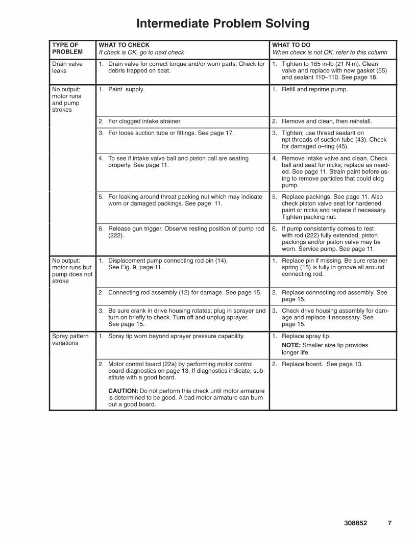
Drain valveleaks
1. Drain valve for correct torque and/or worn parts. Check fordebris trapped on seat.
1. Tighten to 185 in-lb (21 N�m). Cleanvalve and replace with new gasket (55)and sealant 110–110. See page 18.
No output: motor runsand pumpstrokes
1. Paint supply. 1. Refill and reprime pump.
2. For clogged intake strainer. 2. Remove and clean, then reinstall.
3. For loose suction tube or fittings. See page 17. 3. Tighten; use thread sealant on npt threads of suction tube (43). Checkfor damaged o–ring (45).
4. To see if intake valve ball and piston ball are seating properly. See page 11.
4. Remove intake valve and clean. Checkball and seat for nicks; replace as need-ed. See page 11. Strain paint before us-ing to remove particles that could clogpump.
5. For leaking around throat packing nut which may indicateworn or damaged packings. See page 11.
5. Replace packings. See page 11. Alsocheck piston valve seat for hardenedpaint or nicks and replace if necessary.Tighten packing nut.
6. Release gun trigger. Observe resting position of pump rod(222).
6. If pump consistently comes to rest with rod (222) fully extended, pistonpackings and/or piston valve may beworn. Service pump. See page 11.
No output: motor runs butpump does notstroke
1. Displacement pump connecting rod pin (14). See Fig. 9, page 11.
1. Replace pin if missing. Be sure retainerspring (15) is fully in groove all aroundconnecting rod.
2. Connecting rod assembly (12) for damage. See page 15. 2. Replace connecting rod assembly. Seepage 15.
3. Be sure crank in drive housing rotates; plug in sprayer andturn on briefly to check. Turn off and unplug sprayer. See page 15.
3. Check drive housing assembly for dam-age and replace if necessary. See page 15.
Spray pattern variations
1. Spray tip worn beyond sprayer pressure capability. 1. Replace spray tip.
NOTE: Smaller size tip provides longer life.
2. Motor control board (22a) by performing motor controlboard diagnostics on page 13. If diagnostics indicate, sub-stitute with a good board.
CAUTION: Do not perform this check until motor armatureis determined to be good. A bad motor armature can burnout a good board.
2. Replace board. See page 13.
�� ������
Intermediate Problem SolvingTYPE OF PROBLEM
WHAT TO CHECKIf check is OK, go to next check
WHAT TO DOWhen check is not OK, refer to this column
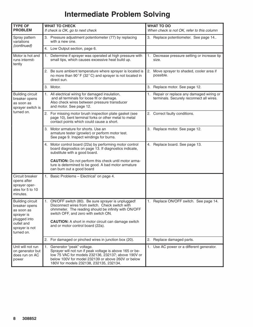
Spray patternvariations(continued)
3. Pressure adjustment potentiometer (77) by replacingwith a new one.
3. Replace potentiometer. See page 14..
(continued)4. Low Output section, page 6.
Motor is hot andruns intermit-tently
1. Determine if sprayer was operated at high pressure withsmall tips, which causes excessive heat build up.
1. Decrease pressure setting or increase tipsize.
2. Be sure ambient temperature where sprayer is located isno more than 90�F (32�C) and sprayer is not located indirect sun.
2. Move sprayer to shaded, cooler area ifpossible.
3. Motor. 3. Replace motor. See page 12.
Building circuitbreaker opensas soon assprayer switch is
1. All electrical wiring for damaged insulation, and all terminals for loose fit or damage. Also check wires between pressure transducer and motor. See page 12.
1. Repair or replace any damaged wiring orterminals. Securely reconnect all wires.
yturned on. 2. For missing motor brush inspection plate gasket (see
page 10), bent terminal forks or other metal to metalcontact points which could cause a short.
2. Correct faulty conditions.
3. Motor armature for shorts. Use an armature tester (growler) or perform motor test. See page 9. Inspect windings for burns.
3. Replace motor. See page 12.
4. Motor control board (22a) by performing motor controlboard diagnostics on page 13. If diagnostics indicate,substitute with a good board.
CAUTION: Do not perform this check until motor arma-ture is determined to be good. A bad motor armaturecan burn out a good board
4. Replace board. See page 13.
Circuit breakeropens aftersprayer oper-ates for 5 to 10minutes.
1. Basic Problems – Electrical’ on page 4.
Building circuitbreaker opensas soon assprayer isplugged intooutlet andsprayer is notturned on.
1. ON/OFF switch (80). Be sure sprayer is unplugged!Disconnect wires from switch. Check switch withohmmeter. The reading should be infinity with ON/OFFswitch OFF, and zero with switch ON.
CAUTION: A short in motor circuit can damage switchand or motor control board (22a).
1. Replace ON/OFF switch. See page 14.
2. For damaged or pinched wires in junction box (20). 2. Replace damaged parts.
Unit will not runon generator butdoes run on ACpower
1. Generator “peak” voltage. Sprayer will not run if peak voltage is above 165 or be-low 75 VAC for models 232136, 232137; above 190V orbelow 100V for model 232139 or above 260V or below180V for models 232138, 232135, 232134.
1. Use AC power or a different generator.
������ �
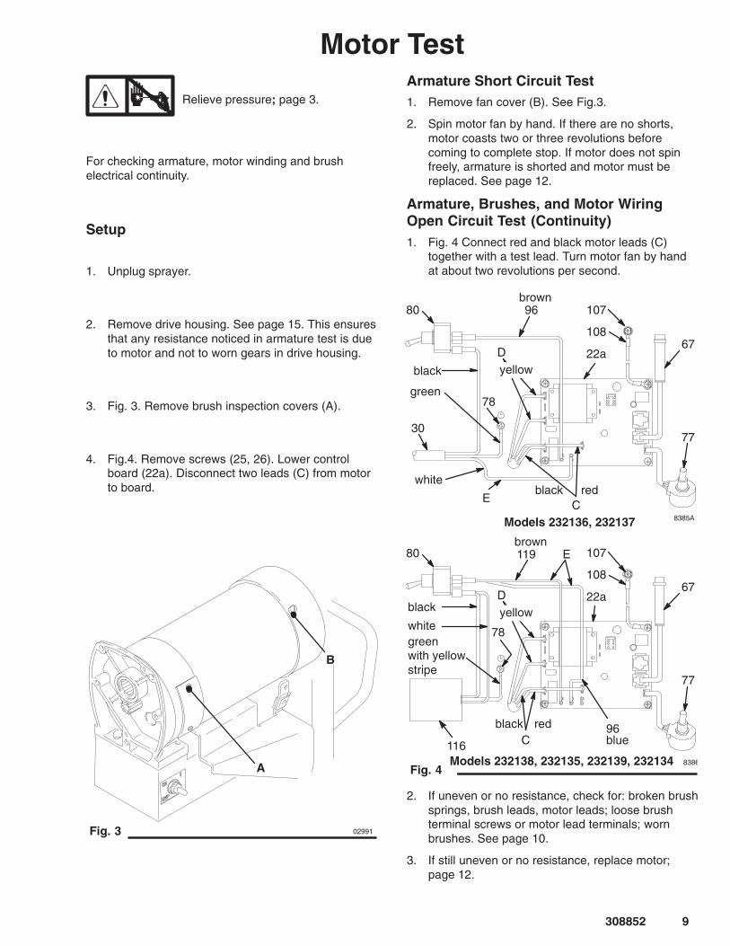
Motor Test
Relieve pressure; page 3.
For checking armature, motor winding and brushelectrical continuity.
Setup
1. Unplug sprayer.
2. Remove drive housing. See page 15. This ensuresthat any resistance noticed in armature test is dueto motor and not to worn gears in drive housing.
3. Fig. 3. Remove brush inspection covers (A).
4. Fig.4. Remove screws (25, 26). Lower controlboard (22a). Disconnect two leads (C) from motorto board.
A
B
Fig. 3 02991
Armature Short Circuit Test1. Remove fan cover (B). See Fig.3.
2. Spin motor fan by hand. If there are no shorts,motor coasts two or three revolutions beforecoming to complete stop. If motor does not spinfreely, armature is shorted and motor must bereplaced. See page 12.
Armature, Brushes, and Motor WiringOpen Circuit Test (Continuity)1. Fig. 4 Connect red and black motor leads (C)
together with a test lead. Turn motor fan by handat about two revolutions per second.
80
green with yellowstripe
8386
Fig. 4
77
67
30
78
C
22a
96
D
E
black
green
whiteblack red
yellow
107
108
Models 232136, 232137
Models 232138, 232135, 232139, 232134
77
67
116
78
C
22aD
E
black
white
black red
yellow
107
108
8385A
96
119
blue
brown
80brown
2. If uneven or no resistance, check for: broken brushsprings, brush leads, motor leads; loose brushterminal screws or motor lead terminals; wornbrushes. See page 10.
3. If still uneven or no resistance, replace motor;page 12.

��� ������
Motor BrushesNOTE: Replace brushes worn to less than13 mm (0.5 in.). Check both brushes. Use Brush Repair Kit236967 for motor brush repair.
Relieve pressure; page 3.
1. Unplug sprayer.
2. Remove both inspection covers (A) and theirgaskets. See Fig.5.
Fig. 5
A
7735A
Models 232135, 232137
3. Push in spring clip (F) and release hooks (G) frombrush holder (B). Pull out spring clip. See Fig. 6.
4. Inspect commutator for excessive pitting, burning orgouging. A black color on commutator is normal.Have commutator resurfaced by a qualified motorrepair shop if brushes seem to wear too fast or arcexcessively. See Step 9.d., also.
5. Repeat for other side.
6. Place a new brush (C) in holder (B) so ramp (H)faces spring. See Fig. 6.
7. Holding spring clip (F) at a slight angle, slide springclip into brush holder and hook it over end ofholder. See Fig. 7. Pull on spring clip to be sure itstays in place. Connect brush lead to blade con-nector (E).
8. Repeat for other side.
9. Test brushes.
a. Remove pump connecting rod pin (14).
WARNINGELECTRIC SHOCK HAZARDDo not touch the brushes, leads, springsor brush holders while the sprayer isplugged in to reduce the risk of electric
shock and serious bodily injury.
b. With sprayer OFF, turn pressure control knobfully counterclockwise to minimum pressure.Plug in sprayer.
c. Turn sprayer ON. Slowly increase pressureuntil motor is at full speed.
d. Inspect brush and commutator contact area forexcessive arcing. Arcs must not trail or circlearound commutator surface.
10. Install brush inspection covers and gaskets.
11. Install pump connecting rod pin (14).
Fig. 6
F
G
E
D
C
B
H
�
�
Motor lead; do not disconnect
� Minimum 13 mm (.5 in.)
�
�����
�����Fig. 7
�
G
C
E
F
������ ���
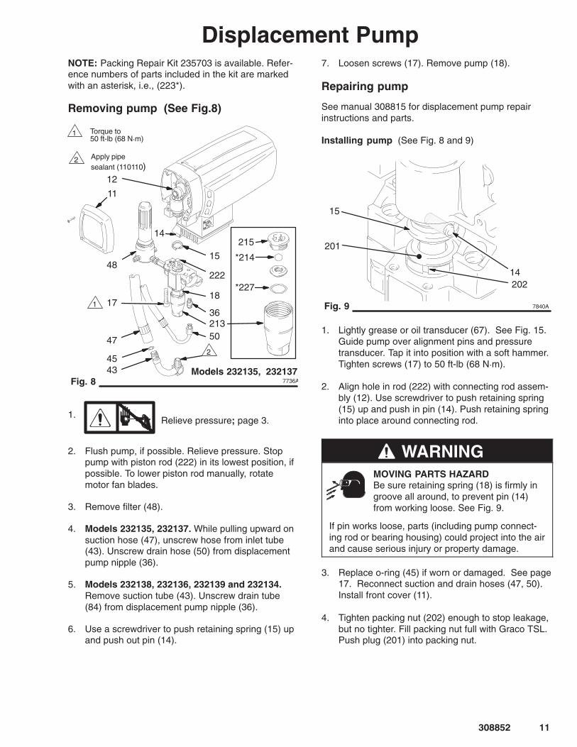
Displacement PumpNOTE: Packing Repair Kit 235703 is available. Refer-ence numbers of parts included in the kit are markedwith an asterisk, i.e., (223*).
Removing pump (See Fig.8)
47
7736A
213
*227
*214
215
222
15
14
1718
50
36
4345
11
Fig. 8
�
�Apply pipesealant (110110)
�
�
48
Torque to 50 ft-lb (68 N�m)
Models 232135, 232137
12
1.Relieve pressure; page 3.
2. Flush pump, if possible. Relieve pressure. Stoppump with piston rod (222) in its lowest position, ifpossible. To lower piston rod manually, rotatemotor fan blades.
3. Remove filter (48).
4. Models 232135, 232137. While pulling upward onsuction hose (47), unscrew hose from inlet tube(43). Unscrew drain hose (50) from displacementpump nipple (36).
5. Models 232138, 232136, 232139 and 232134.Remove suction tube (43). Unscrew drain tube(84) from displacement pump nipple (36).
6. Use a screwdriver to push retaining spring (15) upand push out pin (14).
7. Loosen screws (17). Remove pump (18).
Repairing pump
See manual 308815 for displacement pump repairinstructions and parts.
Installing pump (See Fig. 8 and 9)
14
201
15
Fig. 9
202
7840A
1. Lightly grease or oil transducer (67). See Fig. 15.Guide pump over alignment pins and pressuretransducer. Tap it into position with a soft hammer.Tighten screws (17) to 50 ft-lb (68 N�m).
2. Align hole in rod (222) with connecting rod assem-bly (12). Use screwdriver to push retaining spring(15) up and push in pin (14). Push retaining springinto place around connecting rod.
WARNINGMOVING PARTS HAZARDBe sure retaining spring (18) is firmly ingroove all around, to prevent pin (14)from working loose. See Fig. 9.
If pin works loose, parts (including pump connect-ing rod or bearing housing) could project into the airand cause serious injury or property damage.
3. Replace o-ring (45) if worn or damaged. See page17. Reconnect suction and drain hoses (47, 50).Install front cover (11).
4. Tighten packing nut (202) enough to stop leakage,but no tighter. Fill packing nut full with Graco TSL.Push plug (201) into packing nut.
7741A
Fig. 12
�
16
4
11
3420
25
5
13
2
32
4
3
75
Torque to 80 in-lb (9 N�m)
A
2622
23
�
�
22a
70
Models 232135, 232137
��� ������
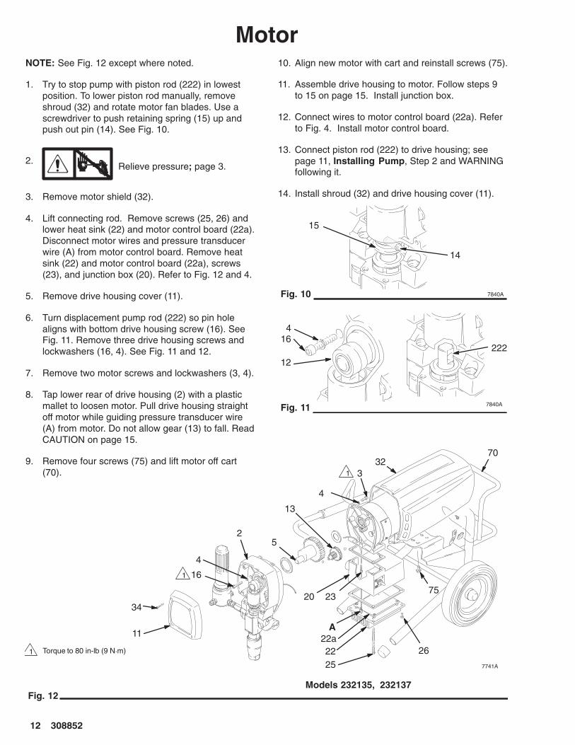
MotorNOTE: See Fig. 12 except where noted.
1. Try to stop pump with piston rod (222) in lowestposition. To lower piston rod manually, removeshroud (32) and rotate motor fan blades. Use ascrewdriver to push retaining spring (15) up andpush out pin (14). See Fig. 10.
2.Relieve pressure; page 3.
3. Remove motor shield (32).
4. Lift connecting rod. Remove screws (25, 26) andlower heat sink (22) and motor control board (22a).Disconnect motor wires and pressure transducerwire (A) from motor control board. Remove heatsink (22) and motor control board (22a), screws(23), and junction box (20). Refer to Fig. 12 and 4.
5. Remove drive housing cover (11).
6. Turn displacement pump rod (222) so pin holealigns with bottom drive housing screw (16). SeeFig. 11. Remove three drive housing screws andlockwashers (16, 4). See Fig. 11 and 12.
7. Remove two motor screws and lockwashers (3, 4).
8. Tap lower rear of drive housing (2) with a plasticmallet to loosen motor. Pull drive housing straightoff motor while guiding pressure transducer wire(A) from motor. Do not allow gear (13) to fall. ReadCAUTION on page 15.
9. Remove four screws (75) and lift motor off cart(70).
10. Align new motor with cart and reinstall screws (75).
11. Assemble drive housing to motor. Follow steps 9to 15 on page 15. Install junction box.
12. Connect wires to motor control board (22a). Referto Fig. 4. Install motor control board.
13. Connect piston rod (222) to drive housing; seepage 11, Installing Pump, Step 2 and WARNINGfollowing it.
14. Install shroud (32) and drive housing cover (11).
15
14
Fig. 10 7840A
16
7840A
222
Fig. 11
4
12

������ ���
Pressure Control Repair
Motor control board removal
1.Relieve pressure; page 3.
2. Remove screws (25, 26) and lower heat sink (22)and motor control board (22a). See Fig. 12.
3. Disconnect wires (C), (D), (96), (E) and 108 frommotor control board (22a). See Fig. 4.
4. Disconnect potentiometer (77) and transducer (67)from motor control board (22a).
5. Remove four screws and motor control board(22a).
6. Install new motor control board (22a) with fourscrews. Reconnect all wires and secure heat sink(22) to junction box (20).
CAUTIONTo reduce the risk of a malfunction:
� Be sure the flat blade of the insulated maleconnector is centered in the wrap–around blade ofthe female connector when the connections aremade.
� Route all wires carefully to avoid interference withthe motor control board or junction box.
Motor control board diagnostics
1.Relieve pressure; page 3.
2. Remove screws (25, 26) and lower heat sink (22)and motor control board (22a). See Fig. 12.
3. Turn ON/OFF switch ON.
4. Observe LED operation and reference followingtable:
LEDBLINKS
SPRAYER OPERATION INDICATES WHAT TO DO
Once Sprayer runs Normal operation Do nothing
Twice Sprayer runs Normal operation Do nothing
Two times repeatedly
Sprayer shuts down and LED continuesto blink two times repeatedly
Run away pressure.Pressure greater than4500 psi.
Replace motor control board.See preceding Motor controlboard removal procedure.
Three times repeatedly
Sprayer shuts down and LED continuesto blink three times repeatedly
Pressure transduceris faulty or missing
Replace pressure transducer
Four times repeatedly
Sprayer shuts down and LED continuesto blink four times repeatedly
Line voltage is toohigh
Lower line voltage to 230 VACfor models 232138, 232135,232134; to 120 VAC for model 232139;and to 100 VAC for models232136, 232137
Five times repeatedly
Sprayer shuts down and LED continuesto blink five times repeatedly
Locked rotor. Motorcan not turn becauseof some mechanicalcondition.
Clear obstruction and replacebroken parts preventing motorfrom turning

��� ������
Power CordModels 232136 and 232137
1.Relieve pressure; page 3.
2. Remove screws (25, 26) and lower heat sink (22).See Fig. 12.
3. Disconnect power cord leads (30), including greenwire to grounding screw (78). See Fig. 4.
4. Loosen strain relief bushing (29). Remove powercord (30).
5. Install new cord (30) in reverse order of disassem-bly.
6. Install heat sink (22). Be sure no leads are pinchedbetween heat sink and junction box (20).
Models 232135, 232138, 232139 and 232134
1.Relieve pressure; page 3.
2. Loosen screw on power cord retainer (120) andremove power cord (30).
3. Install new power cord (30) and tighten screw onpower cord retainer (120).
On/Off Switch1.
Relieve pressure; page 3.
2. Remove screws (25, 26 ) and lower heat sink (22).See Fig. 14.
3. Remove rubber boot (82). See page 20.
4. Disconnect black, white, brown and blue wiresfrom ON/OFF switch (80) and remove switch. SeeFig. 4.
5. Install switch so internal tab of anti–rotation ring(81) engages with vertical groove in threads ofswitch, and external tab engages with slot ofjunction box. See page 20.
6. Powder inside of rubber boot (82) with talcum,then shake excess out of boot. Install nut andrubber boot and tighten.
7. Reconnect black, white, brown and blue wires toON/OFF switch (80).
8. Install heat sink (22) with screws (25, 26 ).See Fig. 14. Be sure no leads are pinched be-tween motor control board or other components.
Pressure Adjusting Potentiometer1.
Relieve pressure; page 3.
2. Remove screws (25, 26 ) and lower heat sink (22).See Fig. 14.
3. Remove potentiometer knob (27).
4. Remove shaft sealing nut (76).
5. Disconnect and remove potentiometer (77).
6. Install and connect new potentiometer (77).
7. Install shaft sealing nut (76).
8. Install potentiometer knob (27).
9. Install heat sink (22) with screws (25, 26 ).See Fig. 14. Be sure no leads are pinched be-tween motor control board or other components.
7742A
25
4
12
2
4, 3
65 7
22
2aA
13
22a
Fig. 14
Note: Filternot shown
16
C
B
26
� Torque to 80 in-lb (9 N�m) �
�
Models 232135, 232137
41
������ ���
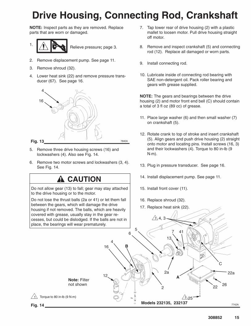
Drive Housing, Connecting Rod, CrankshaftNOTE: Inspect parts as they are removed. Replaceparts that are worn or damaged.
1.Relieve pressure; page 3.
2. Remove displacement pump. See page 11.
3. Remove shroud (32).
4. Lower heat sink (22) and remove pressure trans-ducer (67). See page 16.
4
Fig. 13 7840A
16
5. Remove three drive housing screws (16) andlockwashers (4). Also see Fig. 14.
6. Remove two motor screws and lockwashers (3, 4).See Fig. 14.
CAUTIONDo not allow gear (13) to fall; gear may stay attachedto the drive housing or to the motor.
Do not lose the thrust balls (2a or 41) or let them fallbetween the gears, which will damage the drivehousing if not removed. The balls, which are heavilycovered with grease, usually stay in the gear re-cesses, but could be dislodged. If the balls are not inplace, the bearings will wear prematurely.
7. Tap lower rear of drive housing (2) with a plasticmallet to loosen motor. Pull drive housing straightoff motor.
8. Remove and inspect crankshaft (5) and connectingrod (12). Replace all damaged or worn parts.
9. Install connecting rod.
10. Lubricate inside of connecting rod bearing withSAE non-detergent oil. Pack roller bearing andgears with grease supplied.
NOTE: The gears and bearings between the drivehousing (2) and motor front end bell (C) should containa total of 3 fl oz (89 cc) of grease.
11. Place large washer (6) and then small washer (7)on crankshaft (5).
12. Rotate crank to top of stroke and insert crankshaft(5). Align gears and push drive housing (2) straightonto motor and locating pins. Install screws (16, 3)and their lockwashers (4). Torque to 80 in-lb (9N�m).
13. Plug in pressure transducer. See page 16.
14. Install displacement pump. See page 11.
15. Install front cover (11).
16. Replace shroud (32).
17. Replace heat sink (22).
��� ������
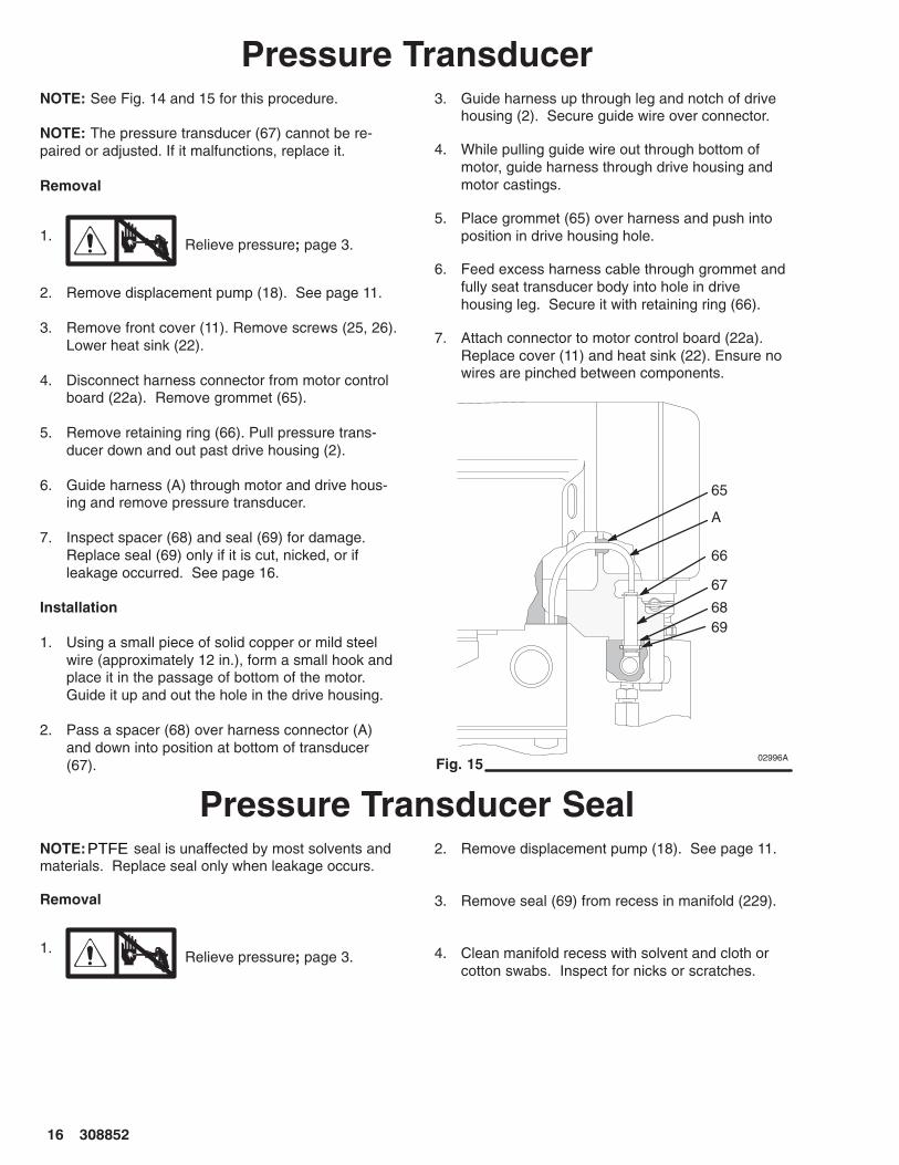
Pressure TransducerNOTE: See Fig. 14 and 15 for this procedure.
NOTE: The pressure transducer (67) cannot be re-paired or adjusted. If it malfunctions, replace it.
Removal
1.Relieve pressure; page 3.
2. Remove displacement pump (18). See page 11.
3. Remove front cover (11). Remove screws (25, 26).Lower heat sink (22).
4. Disconnect harness connector from motor controlboard (22a). Remove grommet (65).
5. Remove retaining ring (66). Pull pressure trans-ducer down and out past drive housing (2).
6. Guide harness (A) through motor and drive hous-ing and remove pressure transducer.
7. Inspect spacer (68) and seal (69) for damage.Replace seal (69) only if it is cut, nicked, or ifleakage occurred. See page 16.
Installation
1. Using a small piece of solid copper or mild steelwire (approximately 12 in.), form a small hook andplace it in the passage of bottom of the motor.Guide it up and out the hole in the drive housing.
2. Pass a spacer (68) over harness connector (A)and down into position at bottom of transducer(67).
3. Guide harness up through leg and notch of drivehousing (2). Secure guide wire over connector.
4. While pulling guide wire out through bottom ofmotor, guide harness through drive housing andmotor castings.
5. Place grommet (65) over harness and push intoposition in drive housing hole.
6. Feed excess harness cable through grommet andfully seat transducer body into hole in drivehousing leg. Secure it with retaining ring (66).
7. Attach connector to motor control board (22a).Replace cover (11) and heat sink (22). Ensure nowires are pinched between components.
02996AFig. 15
67
65
66
A
6869
Pressure Transducer SealNOTE: seal is unaffected by most solvents andmaterials. Replace seal only when leakage occurs.
Removal
1.Relieve pressure; page 3.
2. Remove displacement pump (18). See page 11.
3. Remove seal (69) from recess in manifold (229).
4. Clean manifold recess with solvent and cloth orcotton swabs. Inspect for nicks or scratches.
PTFE
������ ��
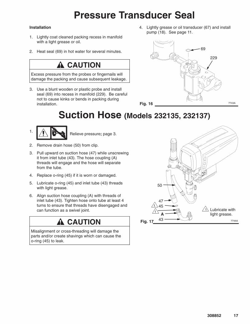
Pressure Transducer SealInstallation
1. Lightly coat cleaned packing recess in manifoldwith a light grease or oil.
2. Heat seal (69) in hot water for several minutes.
CAUTIONExcess pressure from the probes or fingernails willdamage the packing and cause subsequent leakage.
3. Use a blunt wooden or plastic probe and installseal (69) into recess in manifold (229). Be carefulnot to cause kinks or bends in packing duringinstallation.
4. Lightly grease or oil transducer (67) and installpump (18). See page 11.
7743A
229
Fig. 16
69
Suction Hose (Models 232135, 232137)
1.Relieve pressure; page 3.
2. Remove drain hose (50) from clip.
3. Pull upward on suction hose (47) while unscrewingit from inlet tube (43). The hose coupling (A)threads will engage and the hose will separatefrom the tube.
4. Replace o-ring (45) if it is worn or damaged.
5. Lubricate o-ring (45) and inlet tube (43) threadswith light grease.
6. Align suction hose coupling (A) with threads ofinlet tube (43). Tighten hose onto tube at least 4turns to ensure that threads have disengaged andcan function as a swivel joint.
CAUTIONMisalignment or cross-threading will damage theparts and/or create shavings which can cause theo-ring (45) to leak.
7744A
50
47
43
45
A
Fig. 17
�
�
�Lubricate withlight grease.
��� ������
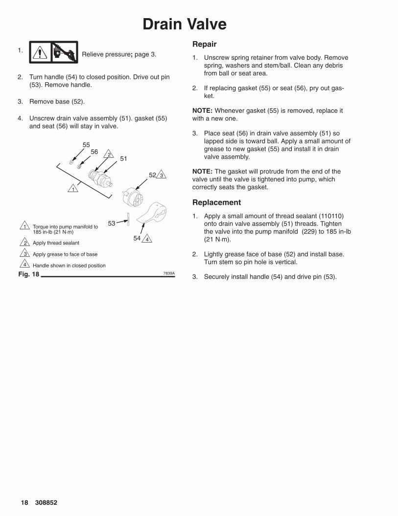
Drain Valve1.
Relieve pressure; page 3.
2. Turn handle (54) to closed position. Drive out pin(53). Remove handle.
3. Remove base (52).
4. Unscrew drain valve assembly (51). gasket (55)and seat (56) will stay in valve.
53
56
52
54Apply thread sealant
Handle shown in closed position
Apply grease to face of base
Torque into pump manifold to185 in-lb (21 N�m)
51
55
Fig. 18 7839A
�
�
�
�
�
�
�
�
Repair
1. Unscrew spring retainer from valve body. Removespring, washers and stem/ball. Clean any debrisfrom ball or seat area.
2. If replacing gasket (55) or seat (56), pry out gas-ket.
NOTE: Whenever gasket (55) is removed, replace itwith a new one.
3. Place seat (56) in drain valve assembly (51) solapped side is toward ball. Apply a small amount ofgrease to new gasket (55) and install it in drainvalve assembly.
NOTE: The gasket will protrude from the end of thevalve until the valve is tightened into pump, whichcorrectly seats the gasket.
Replacement
1. Apply a small amount of thread sealant (110110)onto drain valve assembly (51) threads. Tightenthe valve into the pump manifold (229) to 185 in-lb(21 N�m).
2. Lightly grease face of base (52) and install base.Turn stem so pin hole is vertical.
3. Securely install handle (54) and drive pin (53).
������ ��
Technical DataPower Requirements
Model 232134 240 VAC, 50 Hz,. . . . . . . . . . . . . . . . . . 1 phase, 10A minimum
Model 232138, 232135 230 VAC, 50 Hz,. . . . . . . . . . 1 phase, 10A minimum
Model 232139 120 VAC, 50/60 Hz,. . . . . . . . . . . . . . . 1 phase, 15A minimum
Model 232136, 232137 100 VAC, 50 Hz,. . . . . . . . . . 1 phase, 15A minimum
Generator 3000W minimum. . . . . . . . . . . . . . . . . . . . . . . Working Pressure Range 0–3000 psi. . . . . . . . . . . . . . .
(0–210 bar, 21 MPa)Motor 0.9 HP. . . . . . . . . . . . . . . . . . . . . . . . . . . . . . . . . . . .
with latex at 2000 psi (138 bar, 13.8 MPa)Cycles/Gallon (liter) 566 (150). . . . . . . . . . . . . . . . . . . . . Maximum Delivery Rating 0.6 gpm (2.3 lpm). . . . . . . . Tip Size one gun to 0.024 new tip. . . . . . . . . . . . . . . . . .
with latex at 2000 psi (138 bar, 13.8 MPa)Power Cord 14 AWG, 3 wire, 15 ft (4.5 m). . . . . . . . . . .
Inlet Paint Strainer 16 mesh (975 micron). . . . . . . . . . . . Stainless Steel Screen, reusable
Outlet Filter 60 mesh (238 micron). . . . . . . . . . . . . . . . . . Pump Inlet Size 3/4 npt(f). . . . . . . . . . . . . . . . . . . . . . . . . Fluid Outlet Size 1/4 npsm. . . . . . . . . . . . . . . . . . . . . . . . Sound Data:
Sound Pressure Level 82dB(A)*. . . . . . . . . . . . . . . . . . Sound Power Level 91dB(A)*. . . . . . . . . . . . . . . . . . . . *Measured while spraying with a .017 tip per ISO–3744
Wetted Parts: Zinc-plated carbon steel,. . . . . . . . . . . . . Aluminum, Stainless steel,
Polyethylene, Delrin�, LeatherTungsten carbide, Chrome plating, Polyurethane
NOTE: and Delrin are trademarks of the Company.
Dimensions
Model 232135, 232137 Model 232138, 232136, 232139, 232134
Weight (dry w/o packaging) 61 lb (27.7 kg). . . . . . . . . . Length (handle collapsed) 25.5 in. (648 mm). . . . . . . . Width 15 in. (381 mm). . . . . . . . . . . . . . . . . . . . . . . . . . . . Height 20 in. (508 mm). . . . . . . . . . . . . . . . . . . . . . . . . . .
Weight (dry w/o packaging) 73 lb (33.1 kg). . . . . . . . . . Length 21 in. (533 mm). . . . . . . . . . . . . . . . . . . . . . . . . . . Width 20.5 in. (521 mm). . . . . . . . . . . . . . . . . . . . . . . . . . Height (Handle Down) 28.5 in. (711 mm). . . . . . . . . . . .
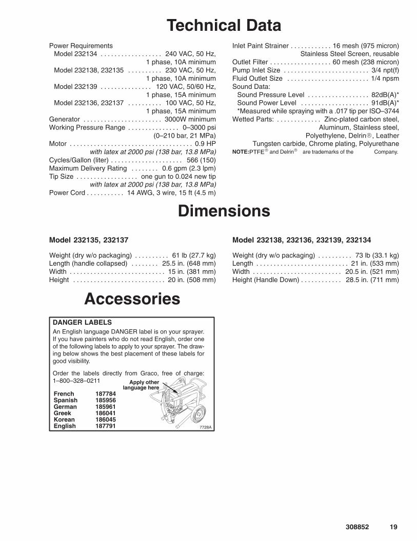
AccessoriesDANGER LABELSAn English language DANGER label is on your sprayer.If you have painters who do not read English, order oneof the following labels to apply to your sprayer. The draw-ing below shows the best placement of these labels forgood visibility.
Order the labels directly from Graco, free of charge:1–800–328–0211
French 187784Spanish 185956German 185961Greek 186041Korean 186045English 187791
Apply otherlanguage here
7728A
PTFE
Models 232135, 232138, 232139, 232134
Model 232137; page 22
����
7745A
49
44
101
102
34
11
48
47
50
5352
18
36 54
51
45
43
10 46
6
5
2a 13
7 41
2
4
12
1415
25
39
38
40
70
37
3132
57
42
26
22
35
1665
8 9
75
8534
9 60
23
24
2021
686769
66
100
7470 Ref
71
72
73 Ref
73 Ref
19
73
Model 232135, Series A
82
17
5556
22a
33
64
99
95
97
67 Ref
78
22a
119 107
77 Ref
80 Ref
Model 232137, Series A
105
111
112
10896
8386A
1
1
114
Pressure Control Box(Bottom View)
76
77
28
78
81
80
27 103
30 Ref
120 Ref
116 Ref
118
12130
116120
117
121 Ref
116 Ref
��� ������
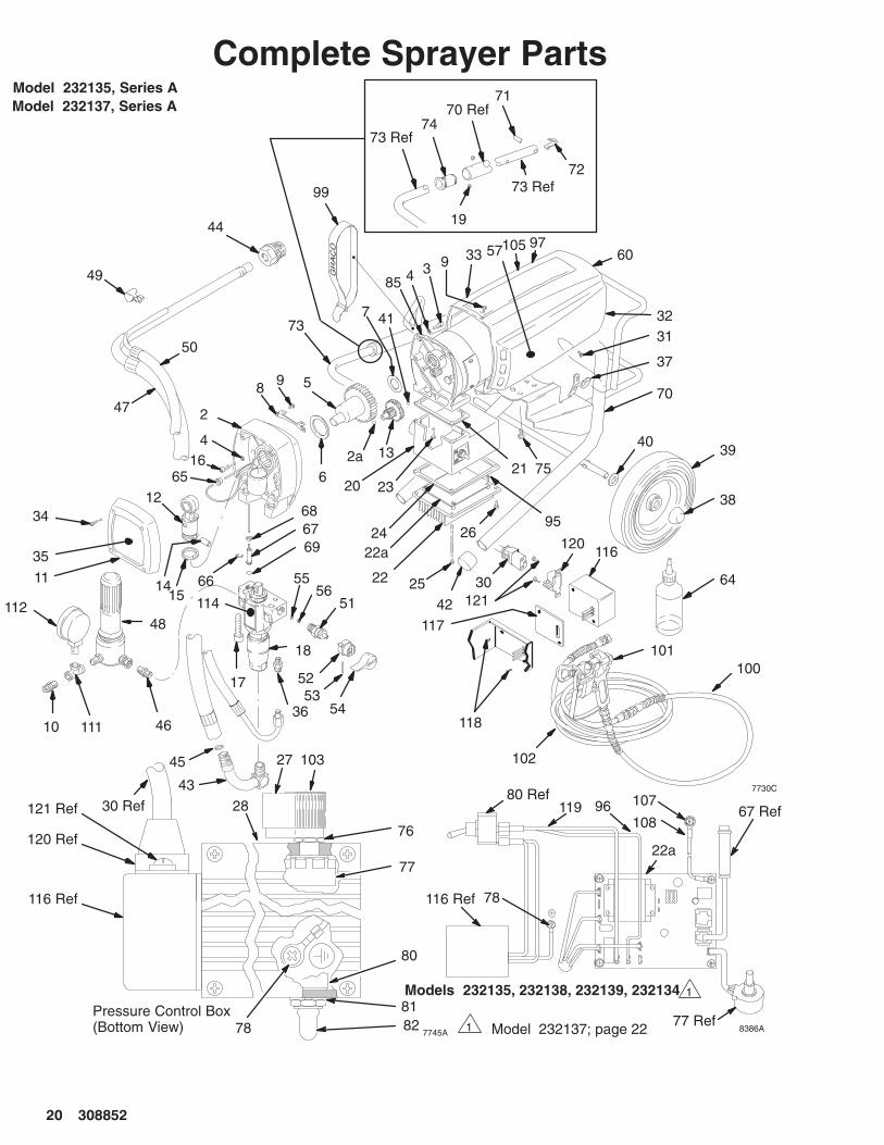
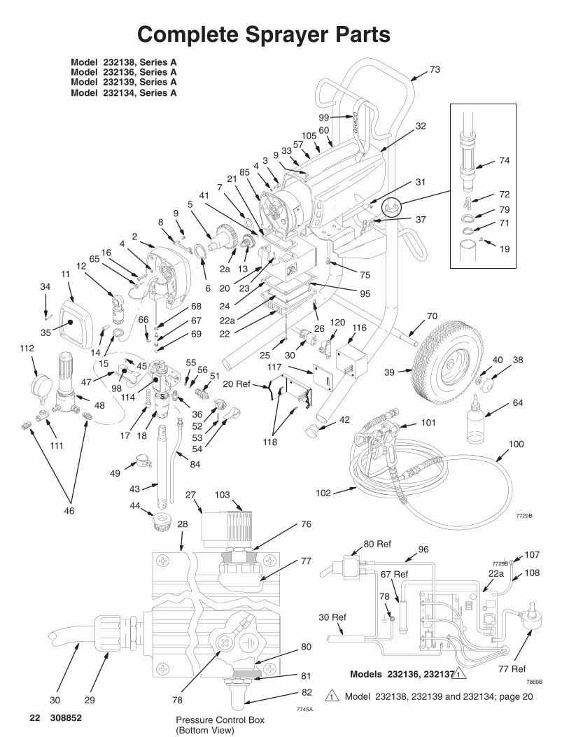
Complete Sprayer Parts

������ ���
Complete Sprayer PartsModel 232135, Series A; Model 232137, Series A
Ref.No. Part No. Description Qty.
Ref.No. Part No. Description Qty.
2 240057 KIT, housing, drive, U-695 12a 100069 BALL, thrust 13 101682 SCREW, sch, 1/4–20 x .625 24 105510 LOCKWASHER, 1/4 hi-collar 55 239979 CRANKSHAFT, U-695; 1
Model 232137 1218242 CRANKSHAFT, U-600; Model 232135 1
6 180131 BEARING, thrust, front 17 107434 BEARING, thrust, rear 18 189270 BRACKET, shield 19 108865 SCREW, panh 410 162453 NIPPLE, 1/4 npt x 14 npsm 111 236366 KIT, cover, front, U-695 112 240519 CONNECTING, rod assy 113 218364 GEAR, assy, 2nd stage 114 176818 PIN, straight 115 176817 SPRING, retaining 116 103345 SCREW, sch, 1/4–20 x 1.25 317 111706 SCREW, mach, sch, 7/16 x 1.75 218 239769 KIT, pump, displacement 1
see manual 30881519 112620 SCREW, 6–32 x 0.187 420 HOUSING, junction box
194435 Model 232135 1189105 Model 232137 1
21 112158 GASKET, motor 122 192844 HEAT SINK, does not include 22a 122a KIT, board, control, motor
see manual 308816240561 Model 232135 1240168 Model 232137 1
23 112379 SCREW, filh, 10–24 x 0.75 224 112159 GASKET, heatsink 125 112381 SCREW, panh, 10–24 x 3.5 226 114417 SCREW, panh, 8–32 x 0.5 227 114273 KNOB, potentiometer 128 193056 LABEL, pressure adjust 129� 114284 CLAMP, power cord 130 CORD, power set 1
241731 Model 232135 1240721 Model 232137 1
31 114053 SCREW, trusshead, 8–32 232 240318 KIT, shield, motor, U-695 1
includes 9, 31, & 37; 33 & 5733 187784 LABEL, DANGER, French 234 114406 SCREW, filh, 8–32 x 1.0 435 192617 LABEL, cover, front 136 111612 ADAPTER, tube 137 114052 NUT, self–retaining 238 112612 CAP, hub 239 112607 WHEEL, semi–pneumatic 240 109570 WASHER, plain 241 100069 BALL, thrust 142 112759 PLUG, tube 243 192808 TUBE, suction 144 235004 STRAINER, 1/2 npsm 145 104938 PACKING, o-ring 146 192644 NIPPLE, long, 1/4 npt x 1/4 npsm 147 187624 HOSE, suction, swivel 148 240711 FILTER, fluid; manual 308249 149 114026 CLIP, spring 150 238345 HOSE, drain assy 151 235014 ASSEMBLY, drain valve 1
includes 55 and 56
52 224807 VALVE, base 153 111600 PIN, grooved 154 187625 HANDLE, drain valve 155 111699 GASKET, seat valve 156 187615 SEAT, valve, lapped 157 LABEL, DANGER, English 2
187791 Model 232135 2189702 Model 232137 2
60 LABEL, WARNING, elec shock 1187975 Model 232138 1193520 Model 232136 1
64 206994 LIQUID, throat seal 165 114296 GROMMET, cable 166 112396 RING, external retaining 167 240514 TRANSDUCER, pressure control 168 189269 SPACER, transducer 169 104319 PACKING, o-ring, 170 239999 FRAME,cart, U-695 171 109567 PIN, spring, straight 272 178565 BUTTON, spring 173 189934 HANDLE, cart 174 280290 BUSHING, sleeve, molded 275 110997 SCREWS, 1/4–20 x .625 476 112382 NUT, shaft sealing 177 236352 POTENTIOMETER, pressure adj 178 110037 SCREW, sltd hex hd, 10–24 x .375 180 SWITCH, toggle 1
111826 Model 232135 1111930 Model 232137 1
81 105658 RING, locking 182 105659 BOOT, toggle 185 KIT, motor, electric, DC
243267 Model 232135 1240035 Model 232137 1
95 114420 SCREW 496 WIRE, electrical, 5”, (F),18 AWG 1
241546 Model 232135 1240495 Model 232137 1
97 192838 LABEL, warning 299 114271 STRAP, hose 1100 238358 HOSE, whip, 3/16” x 3’ 1101 220955 SPRAY GUN, contractor 1
manual 307614102 220794 HOSE, 1/4” x 50’ 1103 193072 LABEL, pressure 1105 192838 LABEL, WARNING, French 1107 114422 SCREW, pnhd 1108 240498 WIRE, ground 1109� 193521 LABEL, caution (not shown) 1110 LABEL, caution (not shown) 1
192839 Model 232135 1189699 Model 232137 1
111 104984 TEE 1112 102814 GAUGE 1114 192849 LABEL, WARNING 1116 241337 FILTER, power inlet 1117 187962 GASKET 1118 111839 SCREW 2119 241545 WIRE, electrical 1120 115098 RETAINER, cord 1121 111840 SCREW 2Extra Warning Labels available free Model 232135 only� Model 232137
PTFE
��� ������
Complete Sprayer Parts
����
7745A
49
101
102
3411
48
5352
18
36
54
43
4446
6
5
2a 13
741
24
12
1415
25 40 38
70
37
31
79
33
42
262235
1665
89
75
8534
9
23
24
20
68
6769
66
100
39
Model 232138, Series A
Pressure Control Box(Bottom View)
76
77
28
7882
81
80
19
45
9847
84
71
72
74
73
56
17
7729B
32
27
5551
21
22a
57
80 Ref
60
103
105
99
64
95
67 Ref
78
22a
96 107
108
77 Ref����
Model 232136, Series A
112
111
Models 232136, 232137 1
Model 232138, 232139 and 232134; page 201
114 s20 Ref
118
11730
116120
30 Ref
2930
Model 232139, Series AModel 232134, Series A

������ ���
Complete Sprayer PartsModel 232138, Series A; Model 232136, Series A; Model 232139, Series A; Model 232134, Series ARef.No. Part No. Description Qty.
Ref.No. Part No. Description Qty.
2 240057 KIT, housing, drive, U-695 12a 100069 BALL, thrust 13 101682 SCREW, sch, 1/4–20 x .625 24 105510 LOCKWASHER, 1/4 hi–collar 55 239979 CRANKSHAFT, U-695; 1
Model 232136, 232138 and 232139 1218242 CRANKSHAFT, U-600; Model 232134 1
6 180131 BEARING, thrust, front 17 107434 BEARING, thrust, rear 18 189270 BRACKET, shield 19 108865 SCREW, panh 511 236366 KIT, cover, front, U-695 112 240519 CONNECTING, rod assy 113 218364 GEAR, assy, 2nd stage 114 176818 PIN, straight 115 176817 SPRING, retaining 116 103345 SCREW, sch, 1/4–20 x 1.25 317 111706 SCREW, mach, sch, 7/16 x 1.75 218 239769 KIT, pump, displacement; 1
Manual 30881519 109032 SCREW, 10–24 x 0.250 420 HOUSING, junction box
194435 Model 232138, 232139 and 232134 1189105 Model 232136 1
21 112158 GASKET, motor 122 192844 HEAT SINK, does not include 22a 122a KIT, board, control, motor
Manual 308816240561 Model 232138 and 232134 1240168 Model 232136 and 232139 1
23 112379 SCREW, filh, 10–24 x 0.75 224 112159 GASKET, heatsink 125 112381 SCREW, panh, 10–24 x 3.5 226 114417 SCREW, panh, 8–32 x 0.5 227 114273 KNOB, potentiometer 128 193056 LABEL, pressure adjust 129� 114284 CLAMP, power cord 130 CORD, power set 1
241731 Model 232134 1241547 Model 232138 1240721 Model 232136 1238964 Model 232139 1
31 114053 SCREW, trusshead, 8–32 232 240318 KIT, shield, motor, U-695 1
includes 9, 31, & 37; 33 & 5733 187784 LABEL, DANGER, French 234 114406 SCREW, filh, 8–32 x 1.0 435 192617 LABEL, cover, front 136 111612 ADAPTER, tube 137 114052 NUT, self–retaining 238 104811 CAP, hub 239 106062 WHEEL, semi–pneumatic 240 101242 RING, retaining, wheel 241 100069 BALL, thrust 142 108691 PLUG, tube 243 192809 TUBE, suction 144 187190 STRAINER 145 112777 SCREW, 8–32 x 3/8 246 193718 NIPPLE, 1/4 npt x 1/4 npsm 247 190321 HANGER, pail 148 240711 FILTER, fluid; Manual 30824949 192648 CLIP, spring 151 235014 ASSY, drain valve; includes 55 and 56 152 224807 VALVE, base 153 111600 PIN, grooved 154 187625 HANDLE, drain valve 1
55 111699 GASKET, seat valve 156 187615 SEAT, valve, lapped 157 LABEL, DANGER, English
187791 Model 232138, 232139 and 232134 2189702 Model 232136 2
60 LABEL, WARNING, elec shock 1187975 Model 232138, 232139 and 232134 1193520 Model 232136 1
64 206994 LIQUID, throat seal 165 114296 GROMMET, cable 166 112396 RING, external retaining 167 240514 TRANSDUCER, pressure control 168 189269 SPACER, transducer 169 104319 PACKING, o-ring, 170 240007 FRAME,cart, U-695 171 110243 RING, retaining, handle 272 111590 BUTTON, spring 273 239998 HANDLE, cart 174 192027 SLEEVE, cart 275 110997 SCREWS, 1/4–20 x .625 476 112382 NUT, shaft sealing 177 236352 POTENTIOMETER, pressure adj 178 110037 SCREW, sltd hex hd, 10–24 x .375 179 183350 WASHER, flat 280 SWITCH, toggle
111826 Model 232138, 232139 and 232134 1111930 Model 232136 1
81 105658 RING, locking 182 105659 BOOT, toggle 184 240017 TUBE, drain 185 KIT, motor, electric, DC
243267 Model 232134 1240511 Model 232138 1240035 Models 232136 and 232139 1
95 114420 SCREW 496 WIRE, electrical, 5”, (F),18 AWG
241546 Model 232138, 232139 and 232134 1240495 Model 232136 1
98 192840 LABEL, WARNING, finger pinch 199 114271 STRAP, hose 1100 238358 HOSE, whip, 3/16” x 3’ 1101 220955 SPRAY GUN, contractor 1
Manual 307614102 240794 HOSE, 1/4” x 50’ 1103 193072 LABEL, pressure 1105 192838 LABEL, WARNING, French 1107 114422 SCREW, pnhd 1108 240498 WIRE, ground 1109� 193521 LABEL, caution (not shown) 1110 LABEL, caution (not shown)
192839 Model 232138, 232139 and 232134 1189699 Model 232136 1
111 104984 TEE 1112 102814 GAUGE 1114 192849 LABEL, WARNING 1116 241337 FILTER, power inlet 1117 187962 GASKET 1118 111839 SCREW 2119 241545 WIRE, electrical, 5 in., 14 AWG 1120 RETAINER, cord 1
115098 Model 232138 and 232134 1115526 Model 232139 1
121 111840 SCREW 2
Extra Warning Labels available free Model 232138, 232139 and 232134� Model 232136
PTFE
��� ������
Graco Standard WarrantyGraco warrants all equipment referenced in this document which is manufactured by Graco and bearing its name to be free fromdefects in material and workmanship on the date of sale by an authorized Graco distributor to the original purchaser for use. With theexception of any special, extended, or limited warranty published by Graco, Graco will, for a period of twelve months from the date ofsale, repair or replace any part of the equipment determined by Graco to be defective. This warranty applies only when the equipmentis installed, operated and maintained in accordance with Graco’s written recommendations.
This warranty does not cover, and Graco shall not be liable for general wear and tear, or any malfunction, damage or wear caused byfaulty installation, misapplication, abrasion, corrosion, inadequate or improper maintenance, negligence, accident, tampering, or sub-stitution of non–Graco component parts. Nor shall Graco be liable for malfunction, damage or wear caused by the incompatibility ofGraco equipment with structures, accessories, equipment or materials not supplied by Graco, or the improper design, manufacture,installation, operation or maintenance of structures, accessories, equipment or materials not supplied by Graco.
This warranty is conditioned upon the prepaid return of the equipment claimed to be defective to an authorized Graco distributor forverification of the claimed defect. If the claimed defect is verified, Graco will repair or replace free of charge any defective parts. Theequipment will be returned to the original purchaser transportation prepaid. If inspection of the equipment does not disclose any defectin material or workmanship, repairs will be made at a reasonable charge, which charges may include the costs of parts, labor, andtransportation.
THIS WARRANTY IS EXCLUSIVE, AND IS IN LIEU OF ANY OTHER WARRANTIES, EXPRESS OR IMPLIED, INCLUDING BUTNOT LIMITED TO WARRANTY OF MERCHANTABILITY OR WARRANTY OF FITNESS FOR A PARTICULAR PURPOSE.
Graco’s sole obligation and buyer’s sole remedy for any breach of warranty shall be as set forth above. The buyer agrees that no otherremedy (including, but not limited to, incidental or consequential damages for lost profits, lost sales, injury to person or property, or anyother incidental or consequential loss) shall be available. Any action for breach of warranty must be brought within two (2) years of thedate of sale.
GRACO MAKES NO WARRANTY, AND DISCLAIMS ALL IMPLIED WARRANTIES OF MERCHANTABILITY AND FITNESS FORA PARTICULAR PURPOSE, IN CONNECTION WITH ACCESSORIES, EQUIPMENT, MATERIALS OR COMPONENTS SOLDBUT NOT MANUFACTURED BY GRACO. These items sold, but not manufactured by Graco (such as electric motors, switches,hose, etc.), are subject to the warranty, if any, of their manufacturer. Graco will provide purchaser with reasonable assistance in mak-ing any claim for breach of these warranties.
In no event will Graco be liable for indirect, incidental, special or consequential damages resulting from Graco supplying equipmenthereunder, or the furnishing, performance, or use of any products or other goods sold hereto, whether due to a breach of contract,breach of warranty, the negligence of Graco, or otherwise.
FOR GRACO CANADA CUSTOMERSThe parties acknowledge that they have required that the present document, as well as all documents, notices and legal proceedingsentered into, given or instituted pursuant hereto or relating directly or indirectly hereto, be drawn up in English. Les parties reconnais-sent avoir convenu que la rédaction du présente document sera en Anglais, ainsi que tous documents, avis et procédures judiciairesexécutés, donnés ou intentés à la suite de ou en rapport, directement ou indirectement, avec les procedures concernées.
ADDITIONAL WARRANTY COVERAGEGraco does provide extended warranty and wear warranty for products described in the “Graco Contractor Equipment WarrantyProgram”.
Phone NumberTO PLACE AN ORDER, contact your Graco distributor, or call this number to identify the distributor closest to you:1–800–690–2894 Toll Free
All written and visual data contained in this document reflects the latest product information available at the time of publication.Graco reserves the right to make changes at any time without notice.
Sales Offices: Minneapolis, DetroitForeign Offices: Belgium, Korea, Hong Kong, Japan
GRACO INC. P.O. BOX 1441 MINNEAPOLIS, MN 55440–1441http://www.graco.com
PRINTED IN USA 308852 May 1998, Revised September 1999