instrument landing system (ils) and distance...
TRANSCRIPT

Instrument Landing System (ILS) andDistance Measuring Equipment (DME)Ground Receiver and Monitor Alarm Testing
Ensuring the safe guidance and exactpositioning of air traffic is dependent uponregular and accurate testing of the ILS and
DME monitor alarms that provide earlyindication of faults or changes in the operatingcharacteristics. This application note discusses
both these systems and describes how the2030 series avionics signal generators may be
used to maintain their operational integrity.
Signal Sourceswww.ifrsys.com
applicationnote
applicationnote

Instrument Landing System - ILSInstrument Landing Systems (ILS) are installed at major
airports throughout the world. The system ensures the safeapproach of aircraft in congested airspace and is essential forcontinuous operation in low visibility and adverse weatherconditions. The system is comprised of two parts - the Localizerthat controls the horizontal alignment and the Glideslope thatcontrols the angle of approach.
Figure 1 - Glideslope course width alarm limits
In order that the integrity of the radiated beams aremaintained in operation, the ILS includes comprehensivemonitors that alert operations staff when changes in the beamcharacteristics exceed predetermined limits. Changes can becaused by:
· transmitter faults or drift· antenna damage· interfering signals· environmental disturbances· multi-path effects
For example, a vehicle parked or moving in the vicinity of theantenna system can cause a temporary disturbance of thetransmitted beam. In order to ensure the accurate guidance ofair traffic approaching the airport it is essential that the monitoralarm levels are periodically checked, and re-aligned ifnecessary. The type and complexity of ILS monitor systemsvaries depending upon the regulations set by the local civilaviation authorities, the category of operation and the systemmanufacturer. The system typically includes integral monitorsthat form part of the system antenna installation, and near andfar field RF monitors that operate from separate antennaplaced at strategic points in the radiated beam. Theperformance of the ILS system is designated as Category I, IIand III, with the tightest limits being set on the Category IIIsystems (there are sub-categories for these systems whichdepend upon other systems being present).
ILS Category Localizer µµ A Deflection IFR Avionics Signal GeneratorDDM limit DDM accuracy at DDM limit
Cat I 0.015 14.5 ± 0.00060Cat II 0.011 10.6 ± 0.00052Cat III 0.009 8.7 ± 0.00048
Independent monitors are provided for the localizer andglideslope and each typically provides alarms for; DisplacementSensitivity, Course Sector Difference Depth of Modulation(DDM), Course Line DDM, Clearance, Sum Depth ofModulation (SDM), Identity Keying and RF Field Level.ILS Waveform Generation
The 2030 series avionics signal generators include thecapability of generating very accurate ILS signals. A large LCDpanel and soft key controlled operator interface, together withspecial firmware, present the operator with easy to use testfacilities. ILS parameters are presented in terms familiar to theavionics engineer such as SDM and DDM. These parameterscan be quickly set to the monitor alarm settings using thekeyboard and adjusted with the rotary control or incrementkeys. The extensive non-volatile memory facilities for storage ofthe signal generator parameters and alarm parameters enablesemi-automatic testing of the monitor system, providingrepeatable results and significantly speed up the test routine.A PC based software support package is also available to aidreport generation and the storage of ILS system parameters.ILS Monitor Alarm Testing
In order to test or calibrate the monitor system an accurateRF ILS signal must be applied to the monitor’s receiver. Themonitors are not placed directly on the approach path so theyreceive signals that typically have non-zero DDM's and differentmodulation depths compared to that seen by an approachingaircraft. The installation is normally checked by flight tests andonce the system integrity has been verified the monitor signallevels are noted and used as reference values for each monitorpoint.
As each monitor point is expected to receive this signal, thealarms are set so that the operators are alerted if the signaldeviates from this reference value. The monitors can be testedby replacing the off air signals with the 2030 avionics signalgenerator whose parameters can be adjusted to simulate therequired off air signal and then deviated from it so that thealarms are tripped. As these parameters are adjusted from theexpected signal the metering circuits, indicators and alarmcircuits can be verified.
The method of ILS waveform generation ensures thataccurate SDM and DDM performance is achieved. This isdescribed in a separate application note.
The use of 2030 series avionics signal generators in thechecking of alarms results in a reduction in the number ofroutine flight tests that are performed and gives an earlyindication of faults or changes in the alarm system.
Signal Sources2 www.ifrsys.com
ILS and DME Ground Receiver and Monitor Alarm Testing

Distance Measuring Equipment - DMEThe DME system has two physically separated sub-systems,
an airborne interrogator and a ground transponder. The system provides the aircraft with distance information
from a ground station. The distance between the aircraft andthe station is the slant range distance (i.e. line of sight) and notthe horizontal distance.
Paired pulses, at a specific spacing, are sent out from theaircraft (interrogator) and are received at the ground station.The ground station (transponder) then transmits paired pulsesback to the aircraft at the same pulse spacing, but on adifferent frequency. The time required for the round trip for thissignal exchange is measured in the airborne DME unit and istranslated into distance (nautical miles) from the aircraft to theground station. A correction factor is applied during thetranslation to cater for the ground station processing delay.
Figure 2 - Distance Measuring Principle
Two types of DME are used, DME/N for en-route andterminal applications, and precision DME/P used on airfieldapproach.2030 series avionics signal generator with DME capability
As stated previously, the interrogation signals use pairs ofpulses that have a defined spacing. The DME option providesthe capability of generating Gaussian shaped RF pulses.Variable control of pulse width, rise and fall times, pulse pairspacing and repetition rate are available giving completeflexibility when defining the required pulse profile. The Gaussianshaped pulses can be generated over the DME range 960 to1215 MHz with identical amplitude and shape, and levelaccuracy of 0.5 dB over the range -110 to +10 dBm.
Figure 3 - Pulses definition in the 2030 signal generator
To be compatible with the ICAO standards recommended inAnnex 10, DME ground equipment has to conform to theEurocae ED57 Minimum Operational PerformanceSpecification (MOPS). This ensures that accurate guidanceinformation is provided and maintained. As with ILS, alarmmonitoring is used. The following describes how the 2030series avionics signal generators, fitted with the DME option,can be used to perform a number of receiver tests and monitoralarm checks.Receiver and Sensitivity Tests
The receiver sensitivity is measured at the DME groundstation cabinet antenna input connector.
The sensitivity is specified to be at least equal to the figuresquoted below (derived from ICAO Annex 10).
Equipment Type Signal Level, (dBm) Reply efficiency (%)
DME/N en-route -91 70DME/N terminal -81 70
The pulse shape of the interrogation test signal has toconform to the DME standard characteristics in duration,rise/fall times and spectrum while performing the tests. Thesensitivity must not vary by more than 1 dB for a reply ratebetween 0 and 2400 pp/s. For high capacity transponders, itmust not vary by more than 3 dB between 2400 pp/s and3600 pp/s. The threshold sensitivity must not change by morethan 3 dB for an interrogation frequency drift to ±100 kHz fromthe assigned channel frequency and for the maximum receiverfrequency drift.
The receiver bandwidth must be such that for interrogationsignals with a rise time between 0.8 and 3 µs the sensitivityfigures are met. When the carrier frequency of interrogationsignals is more than 900 kHz from the nominal channelfrequency at the cabinet input, these signals must not triggerthe transponder. Input signals at the receiver image frequencyand all other spurious within the 960 MHz to 1215 MHz bandhave to be attenuated by at least 75 dB.
3
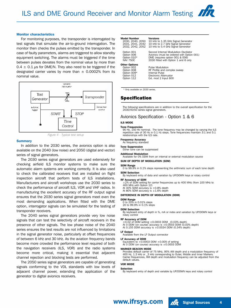
Monitor characteristicsFor monitoring purposes, the transponder is interrogated by
test signals that simulate the air-to-ground interrogation. Themonitor then checks the pulses emitted by the transponder. Incase of faulty parameters, alarms are triggered to allow standbyequipment switching. The alarms must be triggered if the timebetween pulses deviates from the nominal value by more than0.4 ± 0.1 µs for DME/N. They also need to be triggered if thedesignated carrier varies by more than ± 0.0002% from itsnominal value.
Figure 4 - Typical test setup
SummaryIn addition to the 2030 series, the avionics option is also
available on the 2040 (low noise) and 2050 (digital and vector)series of signal generators.
The 2030 series signal generators are used extensively forchecking airfield ILS monitor systems to make sure theautomatic alarm systems are working correctly. It is also usedto check the calibrated receivers that are installed on flightinspection aircraft that perform tests of ILS installations.Manufacturers and aircraft workshops use the 2030 series tocheck the performance of aircraft ILS, VOR and VHF radios. Inmanufacturing the excellent accuracy of the RF output signalensures that the 2030 series signal generators meet even themost demanding applications. When fitted with the DMEoption, interrogator signals can be simulated for the testing oftransponder receivers.
The 2040 series signal generators provide very low noisesignals that can test the selectivity of aircraft receivers in thepresence of other signals. The low phase noise of the 2040series ensures the test results are not influenced by limitationsin the signal generator noise, particularly at offset frequenciesof between 6 kHz and 30 kHz. As the aviation frequency bandsbecome more crowded the performance level required of boththe navigation receivers (ILS, VOR) and the radio systemsbecome more critical, making it essential that adjacentchannel rejection and blocking tests are performed.
The 2050 series signal generators are capable of generatingsignals conforming to the VDL standards with low levels ofadjacent channel power, extending the application of thegenerator to digital avionics receivers.
Model Number Versions2030, 2040, 2050 10 kHz to 1.35 GHz Signal Generator2031, 2041, 2042 10 kHz to 2.7 GHz Signal Generator2032, 2042, 2052 10 kHz to 5.4 GHz Signal Generator
Option 001 Second Internal Modulation OscillatorOption 006 Avionics (must be ordered with Option 001)Option 010* DME (requires option 001 & 006)NAV 750C 2030 fitted with Option 1 and 6 only
Other OptionsOption 002 Pulse ModulationOption 008 RF Profile and complex sweepOption 009* Internal Pulse Option 012 Electronic AttenuatorOption 112 Ext. mod 2 Input 600
* Only available on 2030 series.
Specification
The following specifications are in addition to the overall specification for the2030/40/50 series signal generators.
Avionics Specification - Option 1 & 6ILS MODE
Tone Frequencies 90 Hz, 150 Hz nominal. The tone frequency may be changed by varying the ILSrepetition rate of 30 Hz in 0.1 Hz steps. Tone frequencies maintain 3:1 and 5:1relationships with the ILS rate.
Frequency AccuracyAs frequency standard
Tone SuppressionEither tone can be suppressed
Additional ModulationAvailable for 0% DDM from an internal or external modulation source
SUM OF DEPTH OF MODULATION (SDM)
SDM Range0 to 99.9% in 0.1% steps representing the arithmetic sum of each tone depth
SDM SelectionBy keyboard entry of data and variation by UP/DOWN keys or rotary control
RF Accuracy of SDM±2% of SDM setting for carrier frequencies up to 400 MHz (from 100 MHz to400 MHz with Option 12)At 40% SDM accuracy is ±0.8% depthAt 80% SDM accuracy is ±1.6% depth
DIFFERENCE IN DEPTH OF MODULATION (DDM)
DDM Range0 to 20% in 0.01% steps20 to 99.9% in 0.1% steps
DDM SelectionBy keyboard entry of depth in %, mA or index and variation by UP/DOWN keys orrotary control
RF Accuracy of DDM±0.02 of DDM setting ±0.0003 DDM _(0.03% depth)At 0 DDM (on course) accuracy is ±0.0003 DDM (0.03% depth)At 0.155 DDM accuracy is ±0.0034 DDM (0.34% depth)
LF OutputAvailable from the LF Output connector
LF Accuracy of DDMEquivalent to ±0.0003 DDM ±0.005 of settingAt 0 DDM (on course) accuracy is ±0.0003 DDM
MARKER BEACON MODEProvides default carrier of 75 MHz, 95% AM depth and a modulation frequency of400 Hz, 1.3 kHz or _3 kHz corresponding to Outer, Middle and Inner Markers.Carrier frequencies, AM depth and modulation frequency can be adjusted from thedefault values.
VOR MODE
SelectionBy keyboard entry of depth and variable by UP/DOWN keys and rotary control
Signal Sources 4www.ifrsys.com
ILS and DME Ground Receiver and Monitor Alarm Testing

Signal Sources5 www.ifrsys.com
Bearing ControlRelative phase of 30 Hz tone and subcarrier modulation adjustable from 0° to359.9° in 0.01° steps by entering VOR bearing. Bearing can be entered as TO orFROM the beacon.
Bearing Accuracy±0.05°
Additional modulationAvailable on 0° bearing from an internal or external modulation source
AM Depth Accuracy±3% of setting ±0.5% for carrier frequencies up to 400 MHz (from 100 MHz to400 MHz with Option 12)
FrequencyThe VOR repetition frequency of 30 Hz may be varied in 0.1 Hz steps. Thesubcarrier frequency and deviation maintain a fixed relationship with the VORrepetition rate.
Frequency AccuracyAs frequency standard9.96 kHz subcarrier
AM Range0 to 49.9% depth in 0.1% steps
ModulationFrequency modulated by a 30 Hz tone with settable deviations of 420 Hz, 450 Hz,480 Hz, 510 Hz and 540 Hz
30 Hz TONE
AM Range0 to 49.9% depth in 0.1% stepsArithmetic sum of 30 Hz tone and subcarrier limited to 99.8%
ADF MODEProvides a default carrier of 190 kHz with 30% AM depth at a 1 kHz rate. Carrierfrequency, AM depth and rate, and RF level can be varied from the default values.
SELCAL MODEProvides a facility for modulating the carrier frequency with sequential calling tonesdefined by the SELCAL protocol. The entry of two character pairs is permitted thatdefine the SELCAL code generated to open the audio path of aircraft radios.Default tone duration and gap are 1s and 250 ms respectively and can be variedfrom nominal values.
DME Specification - Option 10Specifications remain as standard 2030 series with the following additions.
DME MODE
RF OUTPUT
Frequency Range960 MHz to 1215 MHz
Level Range-110 dBm to +10 dBm
Absolute LevelAccuracy Standard level error ±0.5 dB
Pulse Pair level Accuracy±0.5 dB
ON-OFF Ratio>80 dB
VIDEO OUTPUT
(REAR PANEL BNC)
Pulse CharacteristicsDouble pulses, Gaussian shaped
Pulse Width2.50 µs to 8.00 µs, resolution 50 ns
Rise Time0.80 µs to 5.75 µs, resolution 50 ns
Fall Time1.50 µs to 5.75 µs, resolution 50 ns
Pulse Pair Spacing9.00 µs to 45.00 µs, resolution 50 ns
Repetition Rate10 pp/s to 6000 pp/s
LevelPseudo TTL (Typically 0 to 4.5 V, 0 to 2.5 V into 50 Ω)
SYNC OUTPUT (REAR PANEL BNC)
Pulse WidthTypically 400 ns
LevelTTL (Typically 0 to 4.5 V, 0 to 2.5 V into 50 Ω)
Rise/Fall TimeTypically 5 ns
EXTERNAL TRIGGER (PULSE INPUT)
CharacteristicsRising-edge, TTL level into 50 ΩMin. pulse width 2 ns
Trigger to SYNC DelayTypically 60 ns
JitterTypically 25 ns
ILS and DME Ground Receiver and Monitor Alarm Testing
IFR, Longacres House, Six Hills Way, Stevenage SG1 2AN, United Kingdom. E-mail: [email protected]
Tel: +44 (0) 1438 742200 Freephone UK: 0800 282 388 Fax: +44 (0) 1438 727601
IFR, 10200 West York Street, Wichita, Kansas,67215-8999, USA. E-mail: [email protected]: +1 316 522 4981 Toll Free USA: 1 800 835 2352 Fax: +1 316 522 1360
As we are always seeking to improve our products, the information in this document gives only a general indication of the product capacity, performance and suitability, none of which shall form part of anycontract. We reserve the right to make design changes without notice. All trademarks are acknowledged. Parent Company IFR Systems, Inc. © IFR Ltd. 2001.
Signal Sources6 www.ifrsys.com Part no. 46891/901
Issue 1
ILS and DME Ground Receiver and Monitor Alarm Testing