instrument valves manifolds - astava hook-ups and interlocking solutions for critical conditions and...
TRANSCRIPT

Instrument valves & manifolds
Instrument Valves & Manifolds
WAY MANIFOLDS

2ASTAVA draws from a strong engineering heritage, as well as seasoned business management. We offer a broad range of products – valves and manifolds suitable for gas and liquid services-as well as full-service solutions that include custom engineering, design and manufacture of Instrument enclosures, modular mounting systems, hook-ups and interlocking solutions for critical conditions and temperatures.
As a customer-focused company, ASTAVA provides high-quality products and engineering solutions that address our customers’ business and technical requirements.For the ASTAVA line, we can offer scalability to design:
Choice of materials from AISI 316(L) to special alloy solutions for highly toxic areas Connections, pressure and temperature ratings varieties Bonnet assemblies offer different stem, seal and material selections Option for standard packing, O-Ring sealing and fugitive emissions bonnets Extensive range of valve configurations and flow schemes Fully equipped instrument enclosures
With over 50 years of designing and manufacturing reliable products and solutions, ASTAVA has acquired an outstanding reputation for quality and customer service. We are always inspired by the need to evolve and stay ahead of the ever-changing marketplace.
OVERVIEW
ASTAVA offers a broad line
of 1,2,3,4 and 5 instrument
manifolds-all available in a wide
range of materials and fully
compatible with the requirements
of the Oil & Gas, Petro-Chemical
and Chemical industries.
In addition to this standard range
of products, ASTAVA has over
3,500 different types of valves and
manifolds available.
INDEX Introduction 02
Manifold features and benefit 03
Bonnet and stem concept 04
Materials of construction 05
1-Way Manifold 06
Ordering information for 1-Way 08
2-Way Manifolds 09
Ordering information for 2-Way 11
3-Way Manifold 12
Ordering information for 3-Way 15
4-Way Manifold 16
Ordering information for 4-Way 17
5-Way Manifold 18
Ordering information for 5-Way 21
Accessories 22
Astava product range 25

3
TE
CH
NIC
AL D
ATA
INSTRUMENT VALVES & MANIFOLDS
MANIFOLD FEATURES AND BENEFITS
Certified for ISO 15848-1:2006(E), (With PEEK or Polyimide seals) Blowout-proof stem Integrated back seat on stem for a secondary seal in the fully opened position Safety stop pin – prevents the bonnet from detaching the body due to vibration Stem seals below stem threads A choice of O-ring materials Oxygen clean per ASTM G-93 as an option 100% Factory Tested Compliance with MSS–SP–99 Direct mount flange design per IEC61518 (MAWP 6000 psig) Working pressure range up to 690 bar (10,000 psig) Working Temperature range up to 550°C (1022°F)
The following unique features of the Astava line of instrument manifolds enable tailoring our high-quality products to the exact requirement of the customer and application:
Features
NACE MR-01-75 / MR-01-03
All manifolds comply with NACE MR-01-75 / MR-01-03 standards.
FULL TRACEABILITY
All products are fully traceable to their components.
CERAMIC STEM BALL TIP Al2O3
Superior hardness prevents deformation of the sealing tip and wear, significantly increasing the lifetime of the product for isolation purposes.
BONNET SELECTIONS
O-ring stem-seal bonnet1. No packing adjustment
2. Extremely low operating torque
3. Compact design
4. Long life-cycle
5. Sealing below stem thread
6. Metal-to-metal bonnet option
Packing stem-seal bonnet1. Wide chemical compatibility range
2. High temperature option (Grafoil®)
3. Low operating torque
4. Sealing below stem thread
WIDE VARIETY OF SEALING MATERIALS
PTFE; Grafoil®; Fluorocarbon FKM; NBR; EPDM; Silicon; and perfluorelastomer providing a wide coverage of applications.
STEM MATERIAL
ST. ST. 316 Ti with chromium carbide diffusion coating1. Long life-cycle 2. Galling prevention
Grafoil —TM GrafTech International Holdings, Inc.

4The special sealing design applied in all ASTAVA Instrument Manifolds features a non-rotating ceramic ball tip.
The chemical composition of a ceramic ball tip is superior in hardness and functionality to a metal ball tip, eliminating sealing tip deformation and significantly increasing the lifetime of the product.
The stem threads are rolled and an integrated back seat design is applied to the packing type of bonnet. Applying a Stainless Steel 316 Ti stem with a chromium carbide diffusion coating results in maximum operation cycles and minimal risk of stem galling. Both packing and O-ring bonnets are designed with sealing below stem threads for maximum protection of the stem threads. For maximum safety, the bonnet design prevents stem blowout, and a locking pin prevents unintentional disassembling of the bonnet.
Grafoil® Down to -60°C (-76°F)
PTFE Down to -60°C (-76°F)
PEEK Down to -60°C (-76°F)
Polyimide Down to -10°C (14°F)
Fluorocarbon FKM Down to -20°C (-4°F)
NBR Down to -34°C (-29°F)
Perfluor Down to -40°C (-40°F)
EPDM Down to -45°C (-49°F)
10,000 psi (690 bar) Available upon request
Packing Material
O-Ring Material
PRESSURE AND TEMPERATURE RATING
690
600
500
400
300
200
100
0 0
1000
2000
3000
4000
5000
6000
7000
8000
9000
10000
0
0 130 230 330 430 530 630 730 830 932 1030 1130 1230
100 200 300 400 500 600 700
Temperature (°C)
Temperature (°F)
Pres
sure
(bar
)
Pres
sure
(Psi
g)
Red:Vent Valves
Blue: Isolate Valves
Green: Equalize Valves
Astava valve bonnets have color coded ring labels for service identification:
HANDLE OPTIONSThe standard handle of the ASTAVA line of instrument manifolds is a Stainless Steel T-bar. For high pressure applications of 10,000 psi (690 bar). an extended T-bar or hand wheel can be applied. Anti-tamper bonnet and key* lock options assure that the manifold is operated by qualified personnel only.
*Not included in order of anti-tamper bonnet manifold. This key should be separately ordered.
TESTINGAll ASTAVA instrument manifolds are factory tested with Nitrogen at 800 psig (55 bar) based on MSS-SP-99. Seats have a maximum allowable leak rate of 0.1 std cm3/min. The Hydrostatic and Helium leak tests are available upon request.
CLEANING All ASTAVA instrument manifolds are cleaned in accordance with the ASTAVA cleaning procedure. Oxygen clean is available in accordance with ASTM G-93.
T-bar
Anti-tamper*
Locking device
For severe service applications, ASTAVA manifolds can be configured with a metal-to-metal seal below the bonnet thread. A dust ring is attached to the bonnet thread or tack weld on the locking pin for extreme vibrating conditions.
Grafoil —TM GrafTech International Holdings, Inc.

5
TE
CH
NIC
AL D
ATA
INSTRUMENT VALVES & MANIFOLDS
Packing Bonnet O-Ring Bonnet Metal-to-Metal Bonnet
No Part Qty. Material Qty. Material Qty. Material
1 Set Screw 1 St.St. 304 1 St.St. 304 1 St.St. 304
2 Bar Handle 1 St.St. 316L 1 St.St. 316L 1 St.St. 316L
3 Gland 1 St.St. 316L - - - -
4 Locking Nut 1 St.St. 316L - - - -
5A Pressure Ring 1 St.St. 316L - - - -
5B Back-up Ring - - 2 Virgin PTFE 2 Virgin PTFE
6A Stem Packing 1 Virgin PTFE - - - -
6B Stem O-Ring - - 1 Fluorocarbon FKM 1 Fluorocarbon FKM
7 Bonnet 1 St.St. 316L 1 St.St. 316L 1 St.St. 316L
8 Stem 1 St.St. 316Ti Chrome-Carbide diffusion coated
1 St.St. 316Ti Chrome-Carbide diffusion coated
1 St.St. 316Ti Chrome-Carbide diffusion coated
9 Ball 1 Ceramic 1 Ceramic 1 Ceramic
10 Dust Protector - - - - 1 Fluorocarbon FKM
Packing Bonnet
O-Ring Bonnet
Metal-to-Metal Bonnet
1
2
3
4
5A
6A
7
8
9
1
2
5B6B
9
7
8
Bottom metal seal protects bonnet’s threads from the fluid. For fugitive emmissions applications
1
2
7
10
8
5B
9
6B
MATERIAL OF CONSTRUCTION

6
STANDARD CONFIGURATION DIMENSIONS 1-WAY MANIFOLDS 1 W
AY
MA
NIF
OLD
S
A
PR
OC
ES
S1/
2-14
NP
T
INS
TR
UM
EN
T1/
2 -
14 N
PT
D Open
C
C
E
NEEDLE VALVE102-06
MULTIPORT VALVE104-06
C
D Open
C
E
B
PR
OC
ES
S1/
2-14
NP
T
INS
TR
UM
EN
T1/
2 -
14 N
PT
(x3
)
A
Inst
rum
ent
Mo
unt
Typ
e
End Connection ASTAVAOrdering
Part Number
Dimensions
A B C D E
Process Instrument Vent / Bleed mm in mm in mm in mm in mm in
RemoteMount
1/2” FNPT 1/2” FNPT - 102-06 70.0 2.76 - - 32.0 1.26 63.0 2.48 45.0 1.77
1/2” FNPT 1/2” FNPT - 102-01 70.0 2.76 - - 32.0 1.26 79.0 3.11 50.0 1.97
1/2” MNPT 1/2” FNPT(3x) - 104-06 110.0 4.33 38.0 1.50 32.0 1.26 63.0 2.48 45.0 1.77
1/2” MNPT 1/2” FNPT(3x) - 104-01 110.0 4.33 38.0 1.50 32.0 1.26 79.0 3.11 50.0 1.97

7
TE
CH
NIC
AL D
ATA
INSTRUMENT VALVES & MANIFOLDS
1 WA
Y M
AN
IFO
LDS
STANDARD CONFIGURATION DIMENSIONS 1-WAY MANIFOLDS
EXTENDED MULTIPORT VALVE108-06
E
D Open
C
C
PROCESS1/2-14 NPT
IN
STR
UM
EN
T1/
2-14
NP
T (x
3)
BA
GAUGE VALVE106-06
E
D Open
C
C
AB
VENT/TEST 1/4-18 NPT
PR
OC
ES
S1/
2-14
NP
T
INS
TR
UM
EN
T1/
2-14
NP
T
Inst
rum
ent
Mo
unt
Typ
e
End Connection ASTAVAOrdering
Part Number
Dimensions
A B C D E
Process Instrument Vent / Bleed mm in mm in mm in mm in mm in
RemoteMount
1/2” MNPT 1/2” FNPT (3x) - 108-06 184.0 7.24 38.0 1.50 32.0 1.26 63.0 2.48 45.0 1.77
1/2” MNPT 1/2” FNPT (3x) - 108-01 184.0 7.24 38.0 1.50 32.0 1.26 79.0 3.11 50.0 1.97
1/2” MNPT 1/2” FNPT 1/4” FNPT 106-06 100.0 3.54 30.0 1.18 32.0 1.26 63.0 2.48 45.0 1.77
1/2” MNPT 1/2” FNPT 1/4” FNPT 106-01 100.0 3.54 30.0 1.18 32.0 1.26 79.0 3.11 50.0 1.97

8
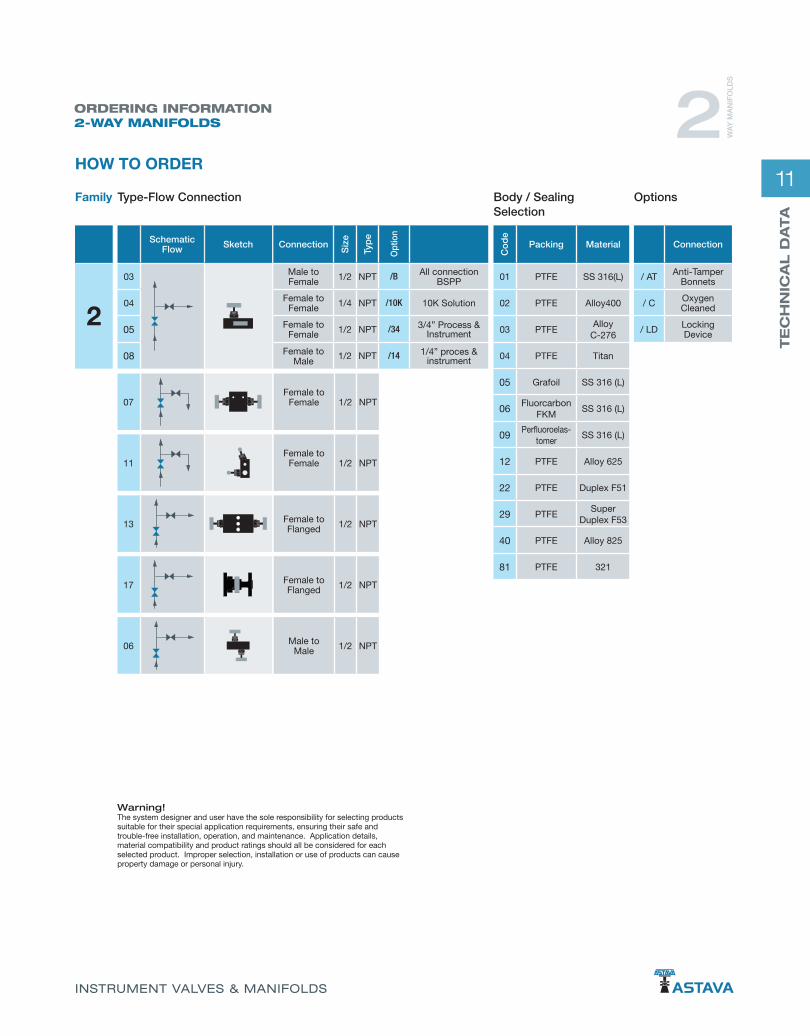
ORDERING INFORMATION1-WAY MANIFOLDS
Warning!The system designer and user have the sole responsibility for selecting products suitable for their special application requirements, ensuring their safe and trouble-free installation, operation, and maintenance. Application details, material compatibility and product ratings should all be considered for each selected product. Improper selection, installation or use of products can cause property damage or personal injury.
1 WA
Y M
AN
IFO
LDS
Grafoil —TM GrafTech International Holdings, Inc.
HOW TO ORDER
1
Connection
/ AT Anti-Tamper Bonnets
/ C Oxygen Cleaned
/ LD Locking Device
Co
de
Packing Material
-01 PTFE SS 316(L)
-02 PTFE Alloy 400
-03 PTFEAlloy
C-276
-04 PTFE Titan
-05 Grafoil SS 316 (L)
-06Fluorcarbon
FKMSS 316 (L)
-09Perfluoroelas-
tomerSS 316 (L)
-12 PTFE Alloy 625
-22 PTFE Duplex F51
-29 PTFESuper
Duplex F53
-40 PTFE Alloy 825
-81 PTFE 321
Schematic Flow Sketch
01
02
03
04
06
08
Connection
Siz
e
Typ
e
Opt
ion
Female to Female 1/4 NPT /B All connections
BSPP
Female to Female 1/2 NPT /10K 10K Solution
Male to Female 1/2 NPT /34 3/4” Process &
Instrument
Male to Female 1/2 NPT
Male to Female 1/2 NPT
Male to Female 1/2 NPT
Type-Flow ConnectionFamily Body / Sealing Selection
Options

9
TE
CH
NIC
AL D
ATA
INSTRUMENT VALVES & MANIFOLDS
STANDARD CONFIGURATION DIMENSIONS 2-WAY DIRECT MOUNT
ISO
LA
TE
VE
NT
D A
E
F
C
PRO
CES
S
INST
RUM
ENT
41,3
(2x)
(1.6
3)
7/1
6-20
UN
F ( 2
x )
Ø12
,0 (
2x )
(Ø0.
47)
VENT1/4-18 NPT
45,0
(1.7
7)
Ø 8.2 (Ø 0.32)
217-06
ISO
LA
TE V
EN
T
PR
OC
ES
S1/
2-14
NP
T
INS
TRU
ME
NT
VENT/PURGE1/4-18 NPT
M8-6H ( 4x )
41,3
(1.6
3)
16,0 (0.63)
45,
0 (1
.77)
Ø12.0 (X2) (0.47)
D
A
C
EF
213-06
* Flange Standard per IEC 61518-A
2 WA
Y M
AN
IFO
LDS
Inst
rum
ent
Mo
unt
Typ
e
End Connection ASTAVAOrdering
Part Number
Dimensions
A B C D E F
Process Instrument Vent / Bleed mm in mm in mm in mm in mm in mm in
Direct Mount
1/2” FNPT *Flange 1/4” FNPT 213-06 85 3.35 - - 65.0 2.56 182 7.17 32.0 1.26 5.0 0.20
*Flange *Flange 1/4” FNPT 217-06 153 6.02 - - 56.0 2.20 82 3.07 65.0 2.56 20.0 0.79

10
ISOLATEV
ENT
A
D
E
F
C
32.0 (1.26)
PROCESS 1/2-14 NPT VENT 1/4-18 NPT
INSTRUMENT1/2-14 NPT
45,0
(1.7
7)
M8-6H ( 2x )
VENT
ISO
LA
TE
BE
F
C
A
VE
NT
1/4-
18 N
PT
PROCESS1/2-14 NPT
32,0(1.26)
INS
TRU
ME
NT
1/2-
14 N
PT
M8-
6H (
2x )
D45.0 (1.77)
D
20,0
(0.7
9)
AE
CB
45.0(1.77)
VENT VENT1/4-18 NPT
INS
TRU
ME
NT
1/2-
14 N
PT
PR
OC
ES
S1/
2-14
NP
T
M8-6H ( 2x )
F
ISOLATE
205-06
211-06
207-06
STANDARD CONFIGURATION DIMENSIONS 2-WAY REMOTE MOUNT 2 W
AY
MA
NIF
OLD
S
Inst
rum
ent
Mo
unt
Typ
e
End Connection ASTAVAOrdering
Part Number
Dimensions
A B C D E F
Process Instrument Vent / Bleed mm in mm in mm in mm in mm in mm in
Remote Mount
1/2” FNPT 1/2” FNPT 1/4” FNPT 205-06 79 3.11 79.0 3.11 32.0 1.26 92.0 3.62 32 1.26 26 1.02
1/2” FNPT 1/2” FNPT 1/4” FNPT 211-06 107 4.21 79.4 3.13 65.0 2.56 65.0 2.56 32 1.26 35 1.38
1/2” FNPT 1/2” FNPT 1/4” FNPT 207-06 156 6.14 - - 65.0 2.56 59.0 2.32 32 1.26 18 0.71
11
TE
CH
NIC
AL D
ATA
INSTRUMENT VALVES & MANIFOLDS
ORDERING INFORMATION2-WAY MANIFOLDS 2 W
AY
MA
NIF
OLD
S
Warning!The system designer and user have the sole responsibility for selecting products suitable for their special application requirements, ensuring their safe and trouble-free installation, operation, and maintenance. Application details, material compatibility and product ratings should all be considered for each selected product. Improper selection, installation or use of products can cause property damage or personal injury.
HOW TO ORDER
2
Connection
/ AT Anti-Tamper Bonnets
/ C Oxygen Cleaned
/ LD Locking Device
Co
de
Packing Material
01 PTFE SS 316(L)
02 PTFE Alloy400
03 PTFEAlloy
C-276
04 PTFE Titan
05 Grafoil SS 316 (L)
06Fluorcarbon
FKMSS 316 (L)
09Perfluoroelas-
tomerSS 316 (L)
12 PTFE Alloy 625
22 PTFE Duplex F51
29 PTFESuper
Duplex F53
40 PTFE Alloy 825
81 PTFE 321
Schematic Flow Sketch
03
04
05
08
Connection
Siz
e
Typ
e
Opt
ion
Male to Female 1/2 NPT /B All connection
BSPP
Female to Female 1/4 NPT /10K 10K Solution
Female to Female 1/2 NPT /34 3/4” Process &
Instrument
Female to Male 1/2 NPT /14 1/4” proces &
instrument
07
11
17
13
06
Female to Female 1/2 NPT
Female to Female 1/2 NPT
Female to Flanged 1/2 NPT
Female to Flanged 1/2 NPT
Male to Male 1/2 NPT
Type-Flow ConnectionFamily Body / Sealing Selection
Options

12
302-06
306-06
41.3
(2X)
(1.6
3)
12.0 (X4) 0.47
8.2 (0.32)
54.0 (2X)2.13
EQUALIZE
ISO
LA
TE
ISO
LA
TE
D
CA
F
B
E
PRO
CES
S (2
x )
1/2-
14 N
PT
45.0 (1.77)
INSTRUMENT
EQUALIZ
E
B
C
E
D
A
F
45,0 (1.77)
12.0 (x4) (0.47)
32,0 (1.26)
M8-6H (2x)
41,3
(1.6
3)
INS
TRU
ME
NT
PR
OC
ES
S (2
x)1/
2-14
NP
T
54,0 (2.13)
120,0 (4.72)
* Flange Standard per IEC 61518-A
STANDARD CONFIGURATION DIMENSIONS 3-WAY DIRECT MOUNT 3 W
AY
MA
NIF
OLD
S
Inst
rum
ent
Mo
unt
Typ
e
End Connection ASTAVAOrdering
Part Number
Dimensions
A B C D E F
Process Instrument Vent / Bleed mm in mm in mm in mm in mm in mm in
DirectMount
1/2” FNPT *Flange - 302-06 181.0 7.13 95.0 3.74 86.0 3.39 82.0 3.11 66.0 2.60 20.0 0.79
1/2” FNPT *Flange - 306-06 161.0 6.34 107.0 4.21 65.0 2.56 150.0 5.91 32.0 1.26 16.0 0.63

13
TE
CH
NIC
AL D
ATA
INSTRUMENT VALVES & MANIFOLDS
329-06
"INSTRUMENT"
"PRO
CES
S" (
2x )
1/2-
14 N
PT
41,3
(2x)
(1.6
3)
32.0 (1.26)
54.0 (2.13)
M8-6H (2x)
45.
0 (1
.77)
12.0 (4X) 0.47EQUALIZE
ISO
LA
TE
BC
DA
EF
ISO
LA
TE
* Flange Standard per IEC 61518-A
* Optinal vent / test ports
STANDARD CONFIGURATION DIMENSIONS 3-WAY DIRECT MOUNT
EQUALIZE
ISOLATE
ISOLATE
54
45 (1.77)
41.3
(x2)
(1.6
3)
7/16-20 UNF-2B (4x)
A
D
B
C
E
303-06
3 WA
Y M
AN
IFO
LDS
Inst
rum
ent
Mo
unt
Typ
e
End Connection ASTAVAOrdering
Part Number
Dimensions
A B C D E F
Process Instrument Vent / Bleed mm in mm in mm in mm in mm in mm in
DirectMount
1/2” FNPT *Flange - 329-06 210.0 8.27 106.0 4.17 65.0 2.56 115.0 4.53 32.0 1.26 16.0 0.63
*Flange *Flange - 303-06 181.0 7.13 95.0 3.74 86.0 3.39 82.0 3.11 66.0 2.60 - -

14
332-06
307-06
C
EQ
UA
LIZ
E
ISO
LA
TE
ISO
LA
TE
A D
45,0
(1.7
7)
PROCESS"(2x)1/2-14 NPT
54,0 (2.13)
INSTRUMENT(2x)1/2-14 NPT
54,0 (2.13)
F
n12,0 (0.47)
E
B
B
A
D
PRO
CES
S1/
2-14
NPT
INST
RUM
ENT
1/2-
14 N
PT
VENT1/4-18 NPT
45,0(1.77)
C
33,0(1.30)
E
ISOLATE
ISOLATE
VENT
STANDARD CONFIGURATION DIMENSIONS 3-WAY REMOTE MOUNT 3 W
AY
MA
NIF
OLD
S
Inst
rum
ent
Mo
unt
Typ
e
End Connection ASTAVA Ordering
Part Number
Dimensions
A B C D E F
Process Instrument Vent / Bleed mm in mm in mm in mm in mm in mm in
RemoteMount
1/2” FNPT 1/2” FNPT - 307-06 185.0 7.28 79.0 3.11 65.0 2.56 90.0 3.54 32.0 1.26 17.0 0.67
1/2” MNPT 1/2”FNPT 1/4” FNPT 332-06 135.0 5.31 87.0 3.43 40.0 1.57 112.0 4.41 40.0 1.57 - -

15
TE
CH
NIC
AL D
ATA
INSTRUMENT VALVES & MANIFOLDS
03
ORDERING INFORMATION3-WAY MANIFOLDS 3 W
AY
MA
NIF
OLD
S
Warning!The system designer and user have the sole responsibility for selecting products suitable for their special application requirements, ensuring their safe and trouble-free installation, operation, and maintenance. Application details, material compatibility and product ratings should all be considered for each selected product. Improper selection, installation or use of products can cause property damage or personal injury.
HOW TO ORDER
3
Connection
/ AT Anti-Temper Bonnets
/ C Oxygen Cleaned
/ LD Locking Device
Co
de
Packing Material
01 PTFE SS 316(L)
02 PTFE Alloy400
03 PTFEAlloy
C-276
04 PTFE Titan
05 Grafoil SS 316 (L)
06Fluorcarbon
FKMSS 316 (L)
09Perfluorelasto-
merSS 316 (L)
12 PTFE Alloy 625
22 PTFE Duplex F51
29 PTFESuper
Duplex F53
40 PTFE Alloy 825
81 PTFE 321
Flow Schematic Sketch
02
Connection
Siz
e
Typ
e
Opt
ion
Female to Flanged 1/2 NPT
/B All connection BSPP
/10K 10K Solution
06
29
07
32
Female to Flanged 1/2 NPT
Female to Flanged 1/2 NPT
Flanged to Flanged - -
Female to Female 1/2 NPT
Male to Female 1/2 NPT
Type-Flow ConnectionFamily Body / Sealing Selection
Options
16
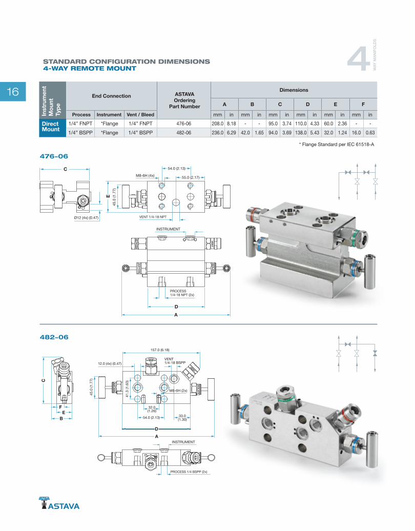
STANDARD CONFIGURATION DIMENSIONS 4-WAY REMOTE MOUNT
476-06
482-06
FE
B
INSTRUMENT
ISO
LA
TE IS
OL
AT
E
VENT
D
C
A
VENT 1/4-18 BSPP
PROCESS 1/4 BSPP (2x)
45.0
(1.7
7)
12.0 (4x) (0.47)
M8-6H (2x)
32.0(1.26)
54.0 (2.13) 33.0(1.30)
41.3
(1.6
3)
157.0 (6.18)
ISO
LA
TE
EQU
ALI
ZE VE
NT
ISO
LA
TE
DA
PROCESS1/4-18 NPT (2x)
VENT 1/4-18 NPT
45.0
(1.7
7)
54.0 (2.13)
55.0 (2.17)M8-6H (4x)
INSTRUMENT
E
C
Ø12 (4x) (0.47)
* Flange Standard per IEC 61518-A
4 WA
Y M
AN
IFO
LDS
Inst
rum
ent
Mo
unt
Typ
e
End Connection ASTAVAOrdering
Part Number
Dimensions
A B C D E F
Process Instrument Vent / Bleed mm in mm in mm in mm in mm in mm in
DirectMount
1/4” FNPT *Flange 1/4” FNPT 476-06 208.0 8.18 - - 95.0 3.74 110.0 4.33 60.0 2.36 - -
1/4” BSPP *Flange 1/4” BSPP 482-06 236.0 6.29 42.0 1.65 94.0 3.69 138.0 5.43 32.0 1.24 16.0 0.63
17
TE
CH
NIC
AL D
ATA
INSTRUMENT VALVES & MANIFOLDS
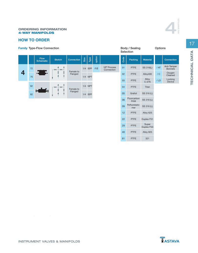
ORDERING INFORMATION4-WAY MANIFOLDS 4 W
AY
MA
NIF
OLD
S
HOW TO ORDER
4
Connection
/ AT Anti-Tamper Bonnets
/ C Oxygen Cleaned
/ LD Locking Device
Co
de
Packing Material
01 PTFE SS 316(L)
02 PTFE Alloy400
03 PTFEAlloy
C-276
04 PTFE Titan
05 Grafoil SS 316 (L)
06Fluorcarbon
FKMSS 316 (L)
09Perfluorelasto-
merSS 316 (L)
12 PTFE Alloy 625
22 PTFE Duplex F51
29 PTFESuper
Duplex F53
40 PTFE Alloy 825
81 PTFE 321
Flow Schematic Sketch
72
76
92
82
Connection
Siz
e
Typ
e
op
tion
Female to Flanged
1/4 BSPP /1/2 1/2” ProcessConnection
1/4 NPT
Female to Flanged
1/4 NPT
1/4 BSPP
Type-Flow ConnectionFamily Body / Sealing Selection
Options

18
502-06
508-06
B
FE
M8-6H (2x)
INST
RUM
ENT
VE
NT
VE
NT
D
C
A
PROCESS (2x) 1/2-14NPT
VENT (2x) 1/4-18 NPT 32.0
(1.26)54.0 (2.13)
45.0 (1.77)
12.0 (4x) (0.47)
41.3
(1.6
3)
110.0 (4.33)
65.0
(2.5
6)
148.0 (5.83)
ISOLATE ISOLATEEQUALIZE
ISO
LA
TE
VE
NT
A
D
F
C
BE
54.0 (2.13)
32.0 (1.26)M8-6H (x2)
41.3
(1.6
3)
54.0 (2.13)
45.0
(1.7
7)
100.
0 (3
.94)
12.0 (x4) (0.47)
INST
RUM
ENT
"TEST"( 2x )1/4-18 NPT
PROCESS (2x)1/2-14 NPT VENT
1/4-18 NPT
EQUALIZ
EQUA
LIZ
STANDARD CONFIGURATION DIMENSIONS 5-WAY DIRECT MOUNT
* Flange Standard per IEC 61518-A
5 WA
Y M
AN
IFO
LDS
Inst
rum
ent
Mo
unt
Typ
e
End Connection ASTAVAOrdering
Part Number
Dimensions
A B C D E F
Process Instrument Vent / Bleed mm in mm in mm in mm in mm in mm in
DirectMount
1/2” FNPT *Flange 1/4” FNPT 502-06 265.0 10.43 41.0 1.61 106.0 4.17 170.0 6.69 32.0 1.26 16.0 0.63
1/2” FNPT *Flange 1/4” FNPT 508-06 220.0 8.66 79.0 3.11 122.0 4.80 140.0 5.51 32.0 1.26 16.0 0.63
Grafoil —TM GrafTech International Holdings, Inc.

19
TE
CH
NIC
AL D
ATA
INSTRUMENT VALVES & MANIFOLDS
STANDARD CONFIGURATION DIMENSIONS 5-WAY DIRECT MOUNT 5 W
AY
MA
NIF
OLD
S
576/1/2-06* Flange Standard per IEC 61518-A
Inst
rum
ent
Mo
unt
Typ
e
End Connection ASTAVA Ordering
Part Number
Dimensions
A B C D E F
Process Instrument Vent / Bleed mm in mm in mm in mm in mm in mm in
DirectMount 1/2” FNPT *Flange 1/4” FNPT 576/1/2-06 210.0 8.27 108.0 4.25 105.0 4.13 115.0 4.53 60.0 2.36 12.5 0.49
VENT
VENT
ISOLATE ISOLATEEQUALIZ
54mm (2.13)
160mm (6.30)25mm (0.98)
258(10.15) 95mm(3.74)
"INSTRUMENT"IEC 61518-A ( 2x )
41.3
mm
(1.6
)
60m
m (2
.3)
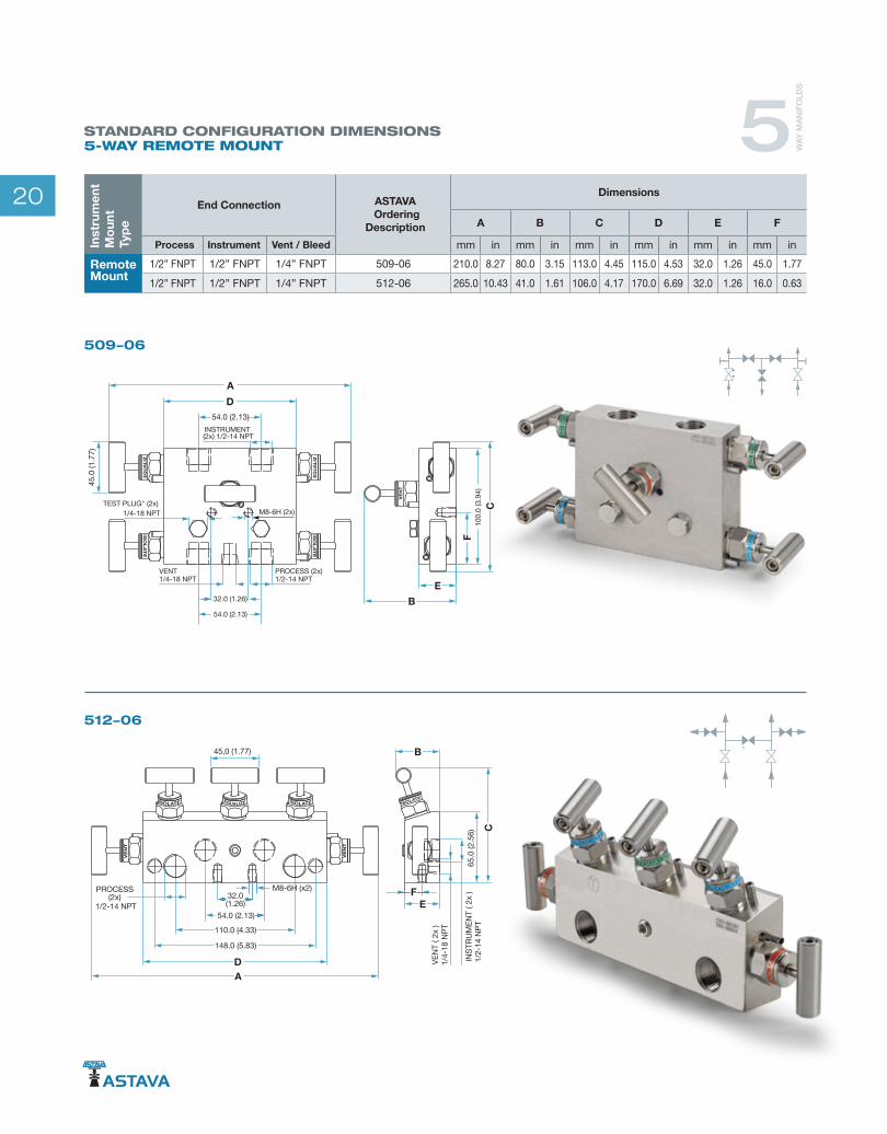
20
509-06
ISO
LA
TE
ISO
LA
TE
DA
B
C
F
E
45.0
(1.7
7)
54.0 (2.13)
M8-6H (2x)
100.
0 (3
.94)
PROCESS (2x)1/2-14 NPT
VENT1/4-18 NPT
32.0 (1.26)
54.0 (2.13)
TEST PLUG" (2x)1/4-18 NPT
INSTRUMENT (2x) 1/2-14 NPT
EQU
ALI
Z
EQU
ALI
Z
VEN
T
512-06
ISOLATE
VE
NT
VE
NT
B
65.0
(2.5
6)
DA
EF
C
45,0 (1.77)
PROCESS (2x)
1/2-14 NPT
INST
RUM
ENT
( 2x
)1/
2-14
NPT
VEN
T ( 2
x )
1/4-
18 N
PT
32.0(1.26)
54.0 (2.13)
M8-6H (x2)
110.0 (4.33)
148.0 (5.83)
ISOLATE ISOLATEEQUALIZE
STANDARD CONFIGURATION DIMENSIONS 5-WAY REMOTE MOUNT 5 W
AY
MA
NIF
OLD
S
Inst
rum
ent
Mo
unt
Typ
e
End Connection ASTAVA Ordering
Description
Dimensions
A B C D E F
Process Instrument Vent / Bleed mm in mm in mm in mm in mm in mm in
RemoteMount
1/2” FNPT 1/2” FNPT 1/4” FNPT 509-06 210.0 8.27 80.0 3.15 113.0 4.45 115.0 4.53 32.0 1.26 45.0 1.77
1/2” FNPT 1/2” FNPT 1/4” FNPT 512-06 265.0 10.43 41.0 1.61 106.0 4.17 170.0 6.69 32.0 1.26 16.0 0.63

21
TE
CH
NIC
AL D
ATA
INSTRUMENT VALVES & MANIFOLDS
ORDERING INFORMATION5-WAY MANIFOLDS 5 W
AY
MA
NIF
OLD
S
HOW TO ORDER
5
Connection
/ AT Anit tamper bonnets
/ C Oxygen cleaned
/ LD Locking device
Co
de
Packing Material
01 PTFE SS 316(L)
02 PTFE Alloy400
03 PTFEAlloy
C-276
04 PTFE Titan
05 Grafoil SS 316 (L)
06Fluorcarbon
FKMSS 316 (L)
09Perfluorelasto-
merSS 316 (L)
12 PTFE Alloy 625
22 PTFE Duplex F51
29 PTFESuper
Duplex F53
40 PTFE Alloy 825
81 PTFE 321
Flow Schematic Sketch
02
08
76
09
12
Connection
Siz
e
Typ
e
op
tion
Female to Flanged 1/2 NPT
/B All connection BSPP
/10K 10K solution
Female to Flanged 1/2 NPT
Female to Flanged 1/4 NPT
Female to Female 1/2 NPT
Female to Female 1/2 NPT
Type-Flow ConnectionFamily Body / Sealing Selection
Options

22
Kit contains 2 gaskets Kit contains 2 gaskets
1/4” MNPT 52.900/14
PTFESpare-087
1/2” MNPT 52.900
GRAFOIL®
Spare-009
BLEED VALVE
BLIND PLUG
MOUNTING GASKET IEC 61518-A
A
A
62
36
HEX 14
A-A
VE
NT
/PU
RG
E1/
8 -
27 N
PT
PROCESS1/2-14 NPT
HEX 27
1/4” MNPT 50.901
1/2” MNPT 50.900
1/4-18 NPT
17
HEX 14
1/2-14 NPT
30
HEX 27
2.9
Ø18
Ø25.1
2.7
Ø17.7
Ø24
A
A
HEX 10
37
HEX 14
A-A
VE
NT
Ø3
PROCESS1/4-18 NPT
A AC
CE
SS
OR
IESACCESSORIES

23
TE
CH
NIC
AL D
ATA
INSTRUMENT VALVES & MANIFOLDS
32
20
90
7290
48.5
58.5
Ø9 (x9)
7272
2
32
PIPE MOUNTING - 2 INCH906/P
MOUNTING BRACKET AISI 316
MOUNTING BRACKET AISI 316
48.5
Ø9 (x9)
90
58.5
90
20
72
32
72
32
2
Kit contains: Bracket, 2x M8x12 bolts.Upon order, please make sure that the Manifold is suitable for bracket mounting.
Kit contains: Bracket, 2x Bolts M8x12 bolts, 2x tie rod, 2x Tie rod brackets, 4x M8 snapnut. Upon order, please make sure that the manifold is suitable for bracket mounting.
WALL MOUNTING906
A AC
CE
SS
OR
IES

24
Fluorocarbon FKM O-Ring
36O° POSITIONING MALE TO MALE60.750
36O° POSITIONING MALE TO FEMALE60.700
GAUGE CONNECTOR
HEX 16
1/2-14 NPT
HEX 32
1/2-14 NPT
76
1/2-14 NPT
1/2-14 NPT
HEX 32
HEX 16
84
5 MM 59.003
57.900
ANTI-TAMPER KEY SYPHON / PULSATION DAMPENER
53
60
5
Not included in order of Anti-Tampered Bonnet Manifod. This key should be ordered separately.
A AC
CE
SS
OR
IES
27 ZKT
Ø6
22
82
1/2-14 NPT
1/2-14 NPT

25
TE
CH
NIC
AL D
ATA
INSTRUMENT VALVES & MANIFOLDS
Instrument Enclosures
Half Body Enclosures Full-Body Enclosures
Probes
Sunshades
Flushing Rings Distribution valves
Monoflanges Slimline Monoflanges
SizesUp to 4" / 10.000 PSIAccording to• ASME B16.5• API• EN 1092.1
Material:• AISI 316(L) • Alloy 400• Alloy C-276• Alloy 625/825 • Duplex• Titan • Additional exotic
• Up to 20 Outlets• 0-690 Bar (0-10.000 psi)• Ball / Needle Type
ASTAVA PRODUCT RANGE

26
VENTURI ASSEMBLIES
ENCLOSURES
ASTAVA PRODUCT RANGE
Equipped Instrument EnclosuresBody Options Full-body GRP enclosures Half-body GRP enclosures Full-body AISI 316 enclosures
Heating Options Steam heater Electrical space heater (black anodized aluminum, AISI 316) Electrical block heater (black anodized aluminum, AISI 316) Thermostat (black anodized aluminum)
Manifolds According to customer application
Mounting Accessories According to ordering information
NUCLEAR VALVES
The products are engineered and manufactured in accordance with ASME and RCC-M international technical standards and are completed according to customer-specific requirements

27
TE
CH
NIC
AL D
ATA
INSTRUMENT VALVES & MANIFOLDS
SEAL POTSACCESSORIES
SPECIAL PRODUCTS
INTERLOCKING SOLUTIONS
Configurations:• 1OO1 (SIL3)• 1OO2 (SIL4)• 2003 (SIL4)• 1OO4 (SIL4)
Unmatched Design• Highest Safety• Optimal Availability• Safety IEC 61508 Approved• SIL3/4 Certified• HIPPS
For Buffer and Drain functions ASTAVA supplies Buffer and Drain pots. The Buffer/Seal pot is used in level application and is designed to act as a buffer for redundant fluids from the process in the wet leg.
Tailored per customer request for a complete package• ASTAVA Engineering• ASTAVA Manufacturing• ASTAVA Assembling• ASTAVA Documentation

AST
AVA
Mni
fold
s 39
0487
7, P
rinte
d 0
6/20
16
The main focus of ASTAVA B.V. is to provide its customer with a complete high-quality solution. Creativity and innovation for new solutions go hand-in-hand with the continuous improvement of our existing product line to assure that ASTAVA continues to play a leading role in its field.
ASTAVA B.V. is approved by the following notified bodies:
ASTAVA B.V. Industrieweg 30, 7944 HS Meppel, The NetherlandsFor pricing and technical information, please contact:
T: +31 522 237030F: +31 522 237040www.astava.com
Inquiries: [email protected]: [email protected]: [email protected]
instrument valves & manifoldsSince 1956