instrumentation, control and monitoring system · 23 instrumentation, control and monitoring system...
TRANSCRIPT

23
Instrumentation, control and monitoring system
David Bloxom* and Mark Wilf
23.1 Introduction
Process control and monitoring in commercial RO desalination systems uti-lizes almost exclusively computer based Supervisory Control and Data Acqui-sition (SCADA) system. The SCADA configuration includes a central computerproviding video display, data storage and reports. The SCADA is connectedthrough communications network with a distributed network of process moni-toring and controlling microprocessors–programmable logic controllers(PLC’s). As shown on the schematic diagram of a control system of RO plant inFig. 23.1, the master PLC, database server and plant operators monitoring sta-tions are located in the control room. The local controllers are distributed at lo-cations adjacent to the equipment being controlled. Each local controller caninclude a full PLC or just be a remote Input/Output (I/O) rack with power sup-ply and input-output adaptors, enclosures for instrumentation and sensors input.If the rack includes a PLC Processor it can operate independently from the Master PLC in the control room in the event of a Master PLC or communi-cations system failure. The local PLC or Remote I/O uses a communica-tion module for data transmission to and from the master PLC located in thecontrol room.
677
*Vice President, Tetar tech Inc., 18311 Bothell Everett Highway, Suite 260, Bothell, WA 98012e-mail: [email protected]
Wilf223.qxp:Wilf223 10/5/09 3:49 PM Page 677

The Master PLC evaluates process parameters of designated system unitand control its operation within the determined limits. Local PLC’s communi-cate with the central control unit usually through fiber optic cables that provideconnection free of electric noises. In some cases of remote systems, a wirelesscommunication between control system components is practiced (1).
Please note that the term PLC is being used as it is the most common mi-croprocessor based system currently being utilized. A Distributed Control Sys-tem (DCS) which is more common in industrial process control applicationscan be utilized in lieu of a PLC based system.
Process control is achieved through evaluating the output signal from sen-sors installed in the plant, and controlling operation of pumps and valves.
Operation of the control system is supported by Uninterruptable PowerSupplies (UPS), that provide sufficient energy (capacity and time duration) tomaintain control system operational during the gap period between the time offailure of the main energy supply and the time that the emergency power gener-ator is operational.
The control equipment should be configured and programmed to return au-tomatically to accurate measurements immediately upon restoration of powerafter a power failure or when transferred to emergency power supply.
678 The Guidebook to Membrane Technology for Wastewater Reclamation
FIG. 23.1 Schematic configuration of a control system.
Wilf223.qxp:Wilf223 10/5/09 3:49 PM Page 678

The components should be of heavy duty type, designed for continuous op-eration in environment of a water treatment plant. Sensor, transmitters and con-trol devices field mounted should be protected from exposure to extremetemperatures and weather conditions.
The control system should have sufficient redundancy to enable maintain-ing process control capability also in case of partial failure of the control equip-ment. Transfer of process control to backup equipment is done automaticallybased on self diagnostic capability of the control equipment.
Majority of currently applied control systems provide the following func-tionality:
1. Protecting system from operating at conditions that may result inequipment damage.
For example: Equipment operation is started in predetermined se-quence. Pumps are protected from operation at inadequate suction pres-sure, at extreme pH or temperature feed water is diverted to drain etc.
2. Maintaining equipment operation within the design process limits.For example: Operation is controlled to maintain design limits of
feed temperature, pressure, flow etc.
3. Activating a design sequence duration of operation of selected equipment For example: During startup and shutdowns valves and pumps are
being activated and maintained in operation for a period required tofill system with feed water or to replace high salinity concentrate.
4. Allowing controlled intervention of operators in system operation.For example: Plant operators are allowed to change setting of oper-
ating parameters or activate/deactivate operation of equipment accord-ing to predetermined authorization.
5. Maintaining production of the design quantity and quality of product water.For example: Feed pressure is adjusted to produce design output ca-
pacity. Permeate is diverted to drain if design quality is not met. Dos-ing pumps are controlled to maintain designed pH and hardness of theproduct water.
6. Storing operating data and generating reports in form of visual displayand hard copy.
For example: Historical results and performance trends reports aregenerated. Membrane performance results are normalized. Operating
Ch. 23 Bloxom, Wilf / Instrumentation, Control and Monitoring System 679
Wilf223.qxp:Wilf223 10/5/09 3:49 PM Page 679

cost data are calculated. Operating data are organized to demonstrateregulatory compliance with required product water quality. Records ofoperating parameters are maintained to satisfy conditions of majorequipment warranty terms.
The control system is usually divided in to functional sections (controlloops) according to logic of plant operation functions, performed by individualsections of the plant.
The functional control loops may include:
• Feed water supply control loop
• Pretreatment control loop
• Main membrane system control loop
• Membrane trains control loops
• Motor control center loop
• Electrical circuits and VFD loop
• Permeate post treatment, storage and pumping control loop
• Residuals management system control loop
Usually each functional section of the plant is controlled by a separate PLCthat communicates with the master PLC using a dedicated communication net-work (distributed control configuration).
Current programmable controllers are increasingly more powerful and arecapable to handle large number of input and output signals, perform extensivecalculation and control functions. It is possible to have a single programmablecontroller to control the complete desalination process, even of a large plant(centralized control configuration).
Decision between distributed or centralized system control configurationsdepends on the preferences of the system designer or the end user.
The detailed design of system configuration, selection of components andoperating software of the control system is developed by process control profes-sionals. However, the design is based on the configuration of wastewater recla-mation system, operational logic and range of operational parameters specifiedby the process engineer that supervises project execution
The advanced wastewater reclamation system is relatively complex as it iscomposed of two autonomous membrane processing systems: feed water mem-brane filtration system, treating feed water to the RO membrane units, and RO
680 The Guidebook to Membrane Technology for Wastewater Reclamation
Wilf223.qxp:Wilf223 10/5/09 3:49 PM Page 680

desalination system operating for reduction of concentration of dissolved con-stituents in the final product.
Out of two membrane units, operating in series, the configuration and oper-ation of membrane filtration pretreatment unit is more complex than configura-tion and operation of the RO unit treating filtration effluent.
Operation of membrane filtration unit is composed of series of relativelyshort and frequent sequences of operational steps:
• Direct (dead end) filtration
• Backwash step applying reverse flow of filtrate
• Air scouring sequence
• Chemical enhanced backwash (CEB)
• Chemical cleaning in place (CIP)
• Integrity test
The first, direct filtration step, is the only process step which results in fil-trate production. The filtrate production step usually lasts between 20–60 min.A constant flow of filtrate is maintained by adjusting feed water pressure (orvacuum on the filtrate side of the membrane) and/or by adjusting throttling ofthe filtrate flow. The objective of the subsequent process steps is to restore waterpermeability of the membrane that rapidly declines during direct filtration step.In addition, the integrity test is conducted periodically to verifying integrity ofthe membrane barrier.
Maintaining constant level of filtrate output and proper sequence and dura-tion of the above operation steps requires precise control of opening/close posi-tion of large number of valves and adjustment of operation of numerous pumpdrivers.
Practically in all cases, the membrane filtration system is composed ofnumber of membrane trains that undergo different operational steps in an over-lapping sequence. The sequence among different trains has to be designed tomaintain constant level of filtrate production from the pretreatment system, de-livered as a feed to the RO unit. The operational sequence of each membraneunit has to account also for the need for sufficient availability of filtrate flowrate for the backwash and scheduled availability of common auxiliary equip-ment, such as air compressors, backwash pumps and chemical dosing pumps.Time required for proper positioning of numerous valves has to be built in tothe overall system control program scheduling equipment operation.
Ch. 23 Bloxom, Wilf / Instrumentation, Control and Monitoring System 681
Wilf223.qxp:Wilf223 10/5/09 3:49 PM Page 681

Compared to the membrane filtration system, the operation of RO unit con-sists of very long periods of operation, during which the constant product waterflow is maintained through gradual adjustment of feed water pressure. Feedpressure fluctuates mainly to compensate for changes of feed water temperatureor slow increased membrane resistance to water permeability due to fouling ofmembrane surface.
Control of maintaining design operating conditions of RO membrane trainis accomplished by two control loops as shown in the Fig. 23.2. Permeate flowrate from the membrane unit is measured by a flow sensor installed on the per-meate line. Te signal from the flow sensor is transmitted to a control unit thatcontrols the driver of the high pressure feed pump. The permeate flow rate isadjusted by changing feed pressure to the RO membrane unit.
The second control loop controls flow rate of the concentrate by adjustingclose/open position of the concentrate valve. The signals of permeate and con-centrate flow rates are compared in the process control unit to maintain the de-sign flow ratio (recovery rate) and product flow.
Similarly to the membrane filtration system, the RO section of the waste-water reclamation plant usually also consists of multiple membrane units,mainly to provide flexibility of adjustment of plant output capacity. Control ofoperation of individual membrane units (RO trains) is different then it is prac-ticed in the case of multiple membrane filtration units. Due to long periods of
682 The Guidebook to Membrane Technology for Wastewater Reclamation
FIG. 23.2 Configuration of control loops for RO membrane unit.
Wilf223.qxp:Wilf223 10/5/09 3:49 PM Page 682
operation of membrane unit in water production step, as compared to frequencyand duration of maintenance steps, automatic scheduling of operation steps ofdifferent membrane units is not required. However, it is sometimes practiced toset up priority of startup and shut down of various RO trains, according to unitsperformance, to improve economics of plant operation.
23.2 Designing instrumentation and control system
The specifications of instrumentation and control system (I&CS) are in-cluded in the request for proposal (RFP) or scope book of the system.
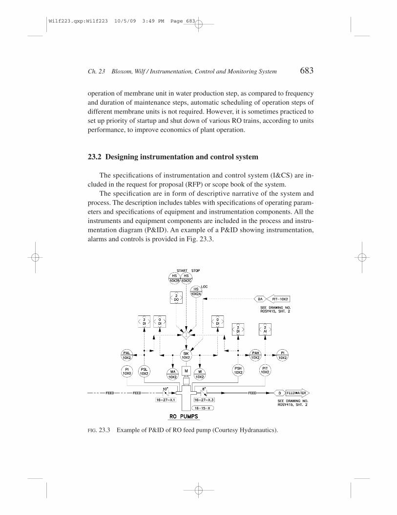
The specification are in form of descriptive narrative of the system andprocess. The description includes tables with specifications of operating param-eters and specifications of equipment and instrumentation components. All theinstruments and equipment components are included in the process and instru-mentation diagram (P&ID). An example of a P&ID showing instrumentation,alarms and controls is provided in Fig. 23.3.
Ch. 23 Bloxom, Wilf / Instrumentation, Control and Monitoring System 683
FIG. 23.3 Example of P&ID of RO feed pump (Courtesy Hydranautics).
Wilf223.qxp:Wilf223 10/5/09 3:49 PM Page 683

23.2.1 Control system specifications
The membrane filtration systems are usually supplied by the manufacturesof the membrane filtration modules or limited number of system integrators,designated by the membrane modules manufacturer. Operating parameters ofthe membrane filtration process are specific for the membrane module type andin some cases are part of proprietary information covered by patents. Therefore,in most of the instances, the supplier of the filtration unit provides also the con-trol system as a part of the overall scope of supply.
The parameters of the RO process are uniform for different membranetypes and are well known. Therefore, development and supply of a control sys-tem for the RO unit could be subcontracted to a third party, specialized in thistype of work.
Control system specification usually starts with the overview of control sys-tem architecture, communication approach and strategy of controlling operationof the membrane system.
The specification then usually follows with general information of control sys-tem configuration, approach strategy and equipment type of major components.
Next the instrumentation equipment requirements are defined in the form ofdata sheets of individual components that includes parameters measured, rangeof measurements, type of instrument, material of construction and approvedmanufacturers.
Designing of control system requires detailed description of membrane sys-tem configuration and operation conditions.
Usually it will include:
• Plant configuration
• Startup and shut down sequence
• Conditions during normal operation including range of operating pa-rameters for major equipment
• Conditions for emergency shut down
• Procedure of plant operation recovery from shut down due to equip-ment failure or due to operation outside the design range of operatingparameters
The detailed description of control system is included in a dedicated sectionof system specifications. It will include:
• Control system narrative description
684 The Guidebook to Membrane Technology for Wastewater Reclamation
Wilf223.qxp:Wilf223 10/5/09 3:49 PM Page 684

• Architecture of the control system
• Description and specifications of hardware
• Description and specifications of software
• Description and specifications of data storage, display and reporting
• Specification of plant equipment and process parameters that will becontrolled
• Approach for operator intervention in process control
23.2.2 Monitoring of system performance
All or some of the following process parameters are being monitored in RO plants:
• Raw water conductivity
• Raw water temperature
• Raw water flow
• Raw water pump suction and discharged pressure
• Raw water turbidity
• Dosing rates of pretreatment chemicals
• Raw water free (combined) chlorine
• Media filters head loss
• Filter effluent turbidity
• Filter effluent particle count
• Filter effluent SDI (MFI)
• Cartridge filters pressure drop
• High pressure pump suction and discharged pressure
• Feed water pressure
• Feed water pH
• Feed water free (combined) chlorine
• RO permeate flow
• RO permeate pressure
Ch. 23 Bloxom, Wilf / Instrumentation, Control and Monitoring System 685
Wilf223.qxp:Wilf223 10/5/09 3:49 PM Page 685

• RO permeate conductivity
• RO permeate temperature
• RO permeate pH
• RO concentrate flow
• RO concentrate pressure
• Dosing rate of post-treatment chemicals
• Product water turbidity
• Product water free (combined) chlorine
• RO permeate storage tank level
The above information is measured and transmitted to PLC as 4–20 mAsignal. According to control process algorithm, the information is utilized todisplay and calculate performance parameters, adjust system operating condi-tions or alarm operators about equipment malfunctioning.
23.2.3 Alarms
The monitoring activity conducted to protect plant equipment includesmonitoring operating parameters of major equipment. This activity includes set-ting alarms and shut off switches to indicate off limits conditions.
The alarms are grouped in several classes of events:
• Equipment failure to execute completely designated task(s). This typeof incomplete operation is usually experienced with motor operatedequipment: valves and pumps.
• Process parameters outside high or low limits. The parameters of con-cern includes all measured water quality parameters (temperature, pH,concentrations, flows, pressures and levels in clear wells and storagetanks.
• Conditions endangering equipment integrity. These could include sig-nals from the sensors indicating presence of constituents in feed waterthat could be harmful to the membranes (oil, oxidants, etc..), excessivevibration of pump bearings, insufficient flow of cooling water, etc..
• Operator generated general alarms.
• Levels in water storage tanks
• Levels in chemical storage tanks
686 The Guidebook to Membrane Technology for Wastewater Reclamation
Wilf223.qxp:Wilf223 10/5/09 3:49 PM Page 686
• Flow of treatment chemicals
• Water temperature
• Water pH
• Water turbidity
• Free (combined) chlorine concentration
• Pressure drop in cartridge filters
• Pumps suction pressure
• Pumps discharged pressure
• Feed pressure
• Permeate pH
• Permeate conductivity
• Permeate temperature
• Permeate pressure
• Concentrate flow
• Concentrate pressure
• Pressure drop in RO system
• Temperature of electric motors
Both alarms and shut-down procedure will start after some delay time,length of which will be defined during the detail design process.
Some of the alarms will be designed to clear when conditions changes, othersmay required acknowledgement of operator or plant supervisor
23.3 Access level
The important issue in a control systems is security and access level. An ex-ample of functional access levels structure is provided below:
Level 1—Anyone Authorized to have minimal access. View any displayscreen except for set point values.
Level 2—Operator level. View any display screen, except for set point val-ues. Ability to stop any equipment. Ability to print reports and enter data.
Ch. 23 Bloxom, Wilf / Instrumentation, Control and Monitoring System 687
Wilf223.qxp:Wilf223 10/5/09 3:49 PM Page 687

Level 3—Plant engineer level. Access to all functions of the operator andability to modify set points and all process parameters.
Level 4—Plant supervisor level. Access to all functions of the plant engi-neer and ability to add/delete users, change access level and changepassword.
Level 5—PLC program developer. Unrestricted access and modification au-thority,
23.4 Specification of scope of work
The scope of work includes specification of scope of supply provided bycontractor of the control system.
In most cases, the scope of supply will include:
• Primary sensors, transmitters, filled instruments and associated mount-ing hardware.
• The programmable controller system including communication mod-ules, modules and racks for input/output signals
• Local control panes and enclosures
• Communication gears
Specifications defines what is the source of reference information thatshould be used by contractor for design of control system, procurement of com-ponents and development of process control software.
Usually, the contractor is also responsible for submitting technical informa-tion on the control system supplied and performing the following work:
• Functional description of the control system
• Technical documentation of the control system
• Factory testing of the control system and components
• Field testing and commissioning of the control system
• Providing engineering support (specified in number of days of fieldpresence) during commissioning and acceptance test of the membranesystem
• Training of plant personnel in operation of the control system
688 The Guidebook to Membrane Technology for Wastewater Reclamation
Wilf223.qxp:Wilf223 10/5/09 3:49 PM Page 688

23.5 Performance optimization through process automation
Presently, application of process automation in RO treatment plants pro-vides limited ability for direct optimization of system performance that wouldresult in achieving optimum product quality or minimum water cost. The limita-tions of process optimization are related to complexity of commercial mem-brane systems and difficulty to develop algorithms of process optimization. Anyoptimization approach has to consider, ion addition to relations of operating pa-rameters, changes of membrane performances due to membrane fouling andcompaction, which are difficult to predict and model.
One of limited direct cost reduction measures related to process automa-tion, which is applied currently in RO systems, is sequencing operation of de-salting units according to predetermined cost parameters. For example, systemproduction capacity is utilized according to variable energy cost or priority ofunits operations is based on prior determined operating cost of individual units(unit required highest operating pressure will be activated last).
Operating cost component that has potential for optimization through con-tinuous on line adjustments is dosing rate of chemicals. In wastewater RO unit,the chemicals used are acid (in majority of cases sulfuric acid is being used) andscale inhibitor.
The above cost reduction measures are applied based on evaluation, con-ducted off line, of the prevailing economic conditions. Optimization of RO unit(or plant performance) so far has been conducted mainly through manual ad-justment of operating parameters in response to change of selective processconditions.
For example, with increase of feed salinity the recovery rate is reduced.This is to prevent an increase of feed pressure and energy consumption. Recov-ery rate could be also reduced or feed pressure increased if lower permeatesalinity is required.
Dosing rate of acid and/or scale inhibitor could be adjusted accordingly toconcentration of scale forming constituents. However, except for pH, continu-ous measurement of relevant species: bicarbonate, calcium and phosphate isdifficult to conduct on line with sufficient accuracy.
Algorithms for RO system optimization are seldom available in any stan-dard form. It can be expected that with increasing number of large desalinationplants an economic incentive for process optimization will increase and there-fore more efforts will be directed towards operation optimization and processalgorithms development.
Ch. 23 Bloxom, Wilf / Instrumentation, Control and Monitoring System 689
Wilf223.qxp:Wilf223 10/5/09 3:49 PM Page 689

23.6 Control system redundancy
Process designers always design redundancy in pumps, equipment trains,etc. but redundancy in the electrical and control systems often gets lost in thedesign.
During the design of facilities, the level of redundancy of all components ofthe treatment processes should be closely considered. There is a balance be-tween budget and reliability that is always in a delicate balance because in-creased redundancy—which leads to increased reliability—costs more money.External influences such as regulatory agencies will also affect the level of re-dundancy that will be required in a project.
During the initial phases of the project, there needs to be close communica-tion with the Client and design team to determine the level of redundancy thatis to be developed by the RO manufacturer as well as the entire plant controlsystem. The design that should be considered would utilize redundant Powersupplies (Utility & generator), segregated power distribution systems, andMotor Control Centers.
Redundancy of the control system is provided through configuration that in-cludes Programmable Logic Controller (PLC) processors located in separatecontrol panels that communicate to and Input/output (I/O) system that are alsolocated in separate control panels that are powered by separate power panelsand each have separate Uninterruptible Power Supply (UPS) Systems.
Redundancy will reduce the potential of inadequate treatment as the resultof a control system failure since the redundancy will keep 1/2 to the entire ROequipment system operating during a PLC failure.
Redundancy will also save operator time because manual intervention willnot be required to operate the RO process in the event of a control system failure.
Figs. 23.4–23.6 show 3 simple examples of control system configurationsthat address redundancy.
Fig. 23.4 shows control system configuration that has no redundancy. Thefailure of any single component–processor, communications media, I/O basehas the potential of completely shutting down a plant until repairs are made.While this is the leas costly to install and implement (program and start-up), ifthe plant is a facility that has significant impact on down stream facilities, thiswould not be the configuration that would be recommended.
The second example (Fig. 23.5) shows redundant PLC processors, with an“off the shelf” hot back-up controller. Each process area has separate I/O racks,each controlling 1/2 of the process systems (i.e., train 1 and 2 on one rack and 3
690 The Guidebook to Membrane Technology for Wastewater Reclamation
Wilf223.qxp:Wilf223 10/5/09 3:49 PM Page 690

and 4 on another). This configuration allows the processes to operate from thecommands of one PLC processor. In the even of a fault of that processor, the HotBack-Up controller automatically switched control to the other PLC processor.
The communications media to each of the independent I/O racks can be re-dundant (recommended) or not. The failure of a single component (with the ex-ception of the hot-back-up controller) would not affect much of the production.
Ch. 23 Bloxom, Wilf / Instrumentation, Control and Monitoring System 691
FIG. 23.4 Configuration of non-redundant control system.
FIG. 23.5 Configuration of partially redundant control system with “hot backup” PLCprocessor.
Wilf223.qxp:Wilf223 10/5/09 3:49 PM Page 691

Worst case scenario would be a 50% reduction in the facility to operate in auto-matic. This option is more costly than the first but still has very simple pro-gramming and is still very simple to start-up and troubleshoots. This optionwould come at approximately a 25% premium over the first.
The last example (Figure 23. 6) would be for all systems to have totally in-dependent PLC systems, each controlling 1/2 of the process systems (same asexample 2). This would be the most reliable to ensure at least 50% of the facil-ity would always be able to operate in automatic. This is the most costly of the3 options (about a 50% premium over option 1 and 25% over option 2. Thistype of configuration is also has the most complicated PLC logic to keep the 2PLCs synchronized and also would be the hardest to troubleshoot.
A final consideration is redundant sensing devices (i.e., pressure transmit-ters, flow transmitters, temperature transmitters, etc.). If the facility is so criticalthat no down time is acceptable, either for economic reasons or public healthand safety, each process variable that is critical for automatic operation shouldhave a redundant/back-up transmitter. This would, for the most part, double thecost of the control system. However there can be justifications if economics orpublic safety dictates the expense
23.7 Implementation of control system
Process control functions are implemented by various control devices, suchas process switches, instrumentation, automatic valves, Programmable Logic
692 The Guidebook to Membrane Technology for Wastewater Reclamation
FIG. 25.6 Configuration of fully redundant control system.
Wilf223.qxp:Wilf223 10/5/09 3:49 PM Page 692

Controllers (PLCs), the facility SCADA system, vendor-supplied packagedcontrol systems, and the process control Ethernet Local Area Network (LAN).Those control devices are used to execute the operating sequences and modes ofthe electrical, mechanical, and process equipment at the facility.
The information system functions are implemented by PLCs, the facilityprocess control Ethernet LAN, the facility SCADA system (including historicaldata logging and analytical reporting utilities), and by a Client administrativeand management system, typically called an “enterprise” or “business” system,located at the facility connected to the Client’s Wide Area Network (WAN).
23.7.1 Implementation options
Various options are available pertaining to the level of technology, com-plexity, functionality, and cost of the control and information systems specifiedfor the facility. Operator preference, facility staffing, cost, current technologiesand industry standards, and interoperability with emerging enterprise systems(such as Maintenance Information Systems) should be considered in selectionof the preferred options. The options can be broken down into the categorieslisted below.
1. Process Control PLCs: It is believed that smaller distributed processcontrol PLCs provide better, more flexible, more fault-tolerant, higher-functionality service than a single centralized master PLC. The hard-ware cost for multiple smaller PLCs is marginally higher, but offers aconsiderable reduction in conduit and wiring installation and mainte-nance costs.
2. Instruments and Process Switches: Traditional analog output processinstruments and contact closure process switches could be employedat the facility. Alternatively, intelligent, programmable process instru-ments and bussed protocol-driven switches and interface devicescould be employed to reduce installation costs and provide higher lev-els of functionality. Device Net and Foundation Fieldbus are examplesof standard facility device and instrument protocols.
3. Redundancy and Fault Tolerance: Some or all equipment can be in-stalled in redundant, non-redundant, or partially redundant reconfigu-rations. Critical items such as facility SCADA system components,process control PLCs, and facility process control Ethernet LAN
Ch. 23 Bloxom, Wilf / Instrumentation, Control and Monitoring System 693
Wilf223.qxp:Wilf223 10/5/09 3:49 PM Page 693

cabling are key areas wherein redundancy and fault tolerance shouldbe considered. Input from the Client is needed on this subject to deter-mine their level of tolerance for working the system during a controlsystem failure. The lower the tolerance for manual control and/or system down time increases the level of redundancy that should beconsidered.
4. Facility Automation: Interfaces and controls should be provided for allfacility processes and equipment to allow full manual operation of allfunctions. Some or all processes and equipment may operate automati-cally without supervision. More highly automated processes will require a smaller staff of operators but a larger and more qualifiedmaintenance staff. As with Redundancy and Fault Tolerance discussedabove, Client input is required to determine the desired degree of auto-matic and unattended operating capabilities. Automation level prima-rily affects PLC and SCADA programming complexity, and therefore,cost. Membrane systems are always designed to operate in automaticunattended mode. The control system should provide the ability forunattended, automatic, sequenced restart.
5. Human Machine Interface (HMI): The SCADA system should providea comprehensive HMI for all facility processes. Stand-alone touch-screen operator interface terminals (OIT) can also be provided at eachprocess control PLC for local HMI capabilities. Providing the localOIT’s would increase hardware and programming costs but providegreater functionality and possibly reduced operating cost.
6. Level of Integration and Remote Access: Facility process control com-puting and information systems may connect to other business infor-mation systems and network resources, or can be isolated from off-sitesystems for security reasons. Security and vulnerability issues shouldbe identified and addressed by a facility Vulnerability Assessment.Client input on the level of connectivity allowed between facility sys-tems and off-site functions and services should be determined. Theseissues will impact remote access and alarm annunciation configurationand capabilities.
7. Local Controls: All equipment manual controls are typically located atMotor Control Centers (MCCs). Local control stations can also beprovided for equipment operating in the field and out of sight of con-
694 The Guidebook to Membrane Technology for Wastewater Reclamation
Wilf223.qxp:Wilf223 10/5/09 3:49 PM Page 694

trollers. The number and configuration of local control stations shouldbe coordinated with the Client.
8. Alarms: Specific equipment and process data points in the facilityshould be configured as alarms in the SCADA, data logging, and auto-dialer functions. Alarm lists, severities, and annunciation requirementsshould be coordinated with the Client.
9. Historical Data Logging: Specific equipment and process data pointsin the facility should be configured to log to a historical database. Thepoint list and logging procedure should be coordinated with the Client.
10. Analytical Reporting: Reporting can be accomplished manually or viapreconfigured report formats operating on data logged in the historicaldatabase. Reports operating out of the historical database can be con-figured with varying levels of automation. The level of automation pri-marily affects report configuration complexity, software requirements,and therefore, front-end cost. The benefits of report automation are re-duced operating costs. The type, requirements, and level of report au-tomation should be coordinated with the Client.
23.7.2 Recommended implementation approach
Process Controllers:
1. Each major subprocess or process area can include a local PLC controlpanel to control the process or processes in the area. Processes shouldbe able to start and operate autonomously from their local PLC with-out SCADA communications; however, SCADA communications maybe required for sequenced automatic facility restart.
2. Distribution of process control PLCs to process locations eliminates theneed for a master PLC and reduces the amount of conduit, wire, and as-sociated maintenance and troubleshooting required to connect I/O points.
3. Vendor-supplied control panels should provide packaged control ofspecified subsystems. Vendor control panels can be specified to interfacewith local area process control PLCs and the facility SCADA system.
4. The SCADA system should provide overall facility supervisory con-trol and monitoring.
Ch. 23 Bloxom, Wilf / Instrumentation, Control and Monitoring System 695
Wilf223.qxp:Wilf223 10/5/09 3:49 PM Page 695

Process switches and instruments:
1. MCCs, stand-alone motor controllers, electrical equipment, machinemonitoring systems, process switches, etc. can connect to localprocess control PLCs via Device Net to the maximum extent practical.
2. Interlocks critical to safety or the protection of life or required to pre-vent catastrophic failures, spills, etc. should be hard-wired to equip-ment controls.
3. Temperature, vibration, and speed feedback sensors for motors over200 hp should be hard-wired to motor controllers.
4. Field instruments and automatic valves can be provided with Founda-tion Fieldbus communications capabilities to the maximum extentpractical.
5. Interfacing instruments to local area PLCs via Device Net or Founda-tion Field Bus reduces field conduit wiring and associated mainte-nance and troubleshooting. Foundation Field Bus also provides remotediagnostic and configuration utilities, which can further reduce main-tenance and operation costs.
Facility and process automation:
1. Facility subprocesses should be automated as specified in written con-trol strategies developed during the design. These control strategies,when used in conjunction with Process and Instrumentation Diagrams(P&IDs) are the communications tool that the deisgnteam uses to de-velop the design and communicate how the facility will operate to theClient.
2. Each subprocess, as well as the entire facility, should be capable offully automatic, unattended start-up and operation unless directed bythe process engineer of Client..
3. Processes should start and operate autonomously from their local PLCwithout SCADA communications; however, SCADA communicationsmay be required for sequenced automatic facility restart. Subprocessautomatic restart modes should be programmed for both SCADA off-line and SCADA on-line operating conditions.
696 The Guidebook to Membrane Technology for Wastewater Reclamation
Wilf223.qxp:Wilf223 10/5/09 3:49 PM Page 696

4. The facility SCADA system should provide overall supervisory con-trol and automatic sequenced restart of the facility following powerfailures or unattended operation for specified durations.
5. Vendor-supplied control panels should interface with local area PLCprocess control panels, and should provide interfaces and functionalityas required to follow the automatic facility restart sequence as directedby the facility SCADA system.
6. The SCADA HMI and local process area operator interface terminalsshould be programmed to facilitate easy input of parameters, recipes,data tables, set points, thresholds, timing sequences, etc. as requiredfor automatic operation modes.
Backup systems, redundancy, and fault tolerance:
1. The level of fault tolerance will be as specified based on discussionbetween the deisgn team and the Client.
2. Hard-wired redundancy will be used as dictated for life safety specifi-cally noted.
3. Electronic control components, such as local area process controlPLCs, should be installed in fault-tolerant and redundant configura-tions as determined. Multiple PLCs may be installed in processes in-volving many pieces of equipment to meet fault tolerancerequirements. If absolute single point fault tolerance is required, all fa-cility PLCs should be installed in fully redundant configurations.
4. SCADA system computer hardware and software should be providedin a fault-tolerant, hot-backup redundant configuration.
5. Intra-facility process data communication media and channels shouldbe provided in redundant configurations.
6. Process control PLC I/O points w should ill be segmented and distrib-uted across process control PLC I/O modules such that the failure of anindividual module reduces process capacity by no more than 50 percent.
7. The facility SCADA system, process control PLCs, and vendor-sup-plied systems should be capable of automatic sequenced restart fol-lowing power failure.
Ch. 23 Bloxom, Wilf / Instrumentation, Control and Monitoring System 697
Wilf223.qxp:Wilf223 10/5/09 3:49 PM Page 697

Vendor-supplied packaged control systems:
1. Vendor-supplied control panels should interface with local area processcontrol PLCs and the facility SCADA through the process control LAN.Interfacing should be via specified hard-wired points or preconfiguredprocess data communication registers in the vendor PLC. Vendor-sup-plied PLCs and communications capabilities should be consistent withfacility standards for ease of integration and maintenance.
2. The vendor-supplied control panels should provide interfaces andfunctionality as required to follow the automatic facility restart se-quence as directed by the facility SCADA system.
3. Remote monitoring and maintenance service capabilities may be pro-vided for vendor-supplied control systems. The connection of thesecapabilities to communication channels should be dependent on Clientsecurity solutions, and should be at the discretion of the Client.
Process data communications:
1. Intra-facility process data communications should occur over redun-dant fiber optic cable Ethernet. This LAN should provide connectivitybetween the facility SCADA system, process control PLCs, Founda-tion Fieldbus instruments, and vendor-supplied PLCs.
2. Inter-facility communications between the facility and the ClientWAN should be dependent on a Client-supplied security solution atthe Client’s discretion.
3. Remote access to the facility SCADA system and process controlPLCs may be provided pending a Client security solution. The remoteaccess could be provided via the Client WAN or by other direct accessmeans, and should be at the discretion of the Client.
4. Alarm annunciation should be performed locally in the facility and re-motely via autodialer. Alarm management and telephony software,such as WIN911 or its equal, should be installed on the facilitySCADA system. Software utilities and functions can include alarmmanagement and voice, pager, or e-mail annunciation, and remote dialin acknowledgement. The connection of software-based autodialer ca-pabilities to communications media is dependent on a Client securitysolution and should be solely at the discretion of the Client.
698 The Guidebook to Membrane Technology for Wastewater Reclamation
Wilf223.qxp:Wilf223 10/5/09 3:49 PM Page 698

5. A hardware/hard-wired autodialer system can be provided in the eventthe Client does not allow connection of software autodialer equipmentto communications media. Critical alarm points should be hard-wiredto the autodialer.
Process equipment interface:
1. Discrete indicators, switches, pilot lights, etc. should be provided atMCCs and stand-alone motor controllers for indication and control.
2. Local control stations, such as Lock Out Stop stations, should be pro-vided for equipment operating in the field away from associated motorcontrol equipment.
3. Touch-screen operator interfaces should be at provided at localprocess control PLCs to monitor process parameters and update setpoints, thresholds, timing sequences, ramp-soak profiles, etc., as required to modify automatic operation characteristics.
4. Vendor-supplied packaged control panels should provide touch-screenoperator interfaces, consistent with facility standards and discrete indi-cation and control devices as specified.
5. The facility SCADA system can host HMI Client applications runningon computers at the locations throughout the plant; HMI Clients canrun on desktop or laptop computers, which can be connected to theprocess control LAN at any part of the facility. The SCADA HMIshould be programmed for easy review and modification of all param-eters and sequences required for automatic operation modes.
6. Remote access to the facility SCADA system, process control PLCs,and smart instruments should be provided pending. Remote access canbe provided via the Client WAN or other direct access means, andshould be at the discretion of the Client.
7. Hardware- or software-based autodialers discussed above can provideautomatic alarm dial-out annunciation to on-call maintenance and op-erations staff. Software-based autodialer applications can also providealarm management and remote dial-in acknowledgement functions.
8. All process and equipment data in the facility can be made available toalarm management and annunciation functions. Alarm lists and annun-ciation requirements should be coordinated with the Client.
Ch. 23 Bloxom, Wilf / Instrumentation, Control and Monitoring System 699
Wilf223.qxp:Wilf223 10/5/09 3:49 PM Page 699

9. All process and equipment data in the facility can be made available tohistorical data logging and analytical reporting functions. The pointlist and logging and reporting requirements should be coordinatedwith the Client.
Interface to other facility systems:
1. Many jurisdictions require that a fire alarm system be installed inwater treatment plants. This requirement is typically due to the storageof oxidizers such as chlorine and other chemicals typical to watertreatment facilities. These systems are typically tied directly to an offsite licensed alarm monitoring company. It is also typical for thesesystems to be tied to the facility SCADA system. This interfaces canallow for alarm horn and light initiation, interfacing to certain systemsthat should be shut down in the event of a fire, and for call out of plantpersonnel through the autodialer.
2. Security systems use many types of intrusion detection devices suchas motion detectors, door switches, and video based (camera) motiondetecting. These systems are commonly tied to the SCADA system ina manner that allows for Security System video signals to alert plantstaff and allow them to access to security camera views in all parts ofthe plant form any SCADA computer.
Business information systems interface:
1. The Client Maintenance Information System can be available on theClient WAN but may not be available to the facility process controland SCADA LAN. A manual transfer of process data to the ClientWAN may be required.
2. Lab and SCADA PCs and laptops can connect to the facility processcontrol LAN to run PLC programming software, SCADA configura-tion, Client and server software, smart instrument configuration anddiagnostic software, operator interface configuration software, histori-cal data logs, etc. Manual disconnection from the process control LANand connection to the Client WAN may be required to obtain Client ISresources or to transfer facility process data to the Client WAN.
3. Connection of the facility process control and SCADA LAN to the ClientWAN to achieve full enterprise integration should be dependent on aClient security solution to limit exposure to computing system threats.
700 The Guidebook to Membrane Technology for Wastewater Reclamation
Wilf223.qxp:Wilf223 10/5/09 3:49 PM Page 700

4. The process data historian, historical database, and trending and re-porting functions should be installed on computers connected to thefacility process control LAN. Manual transfer of historical data to theClient WAN may be required for access by WAN users.
5. Communications between the facility and the Client WAN can occurover an existing T1 phone line. Facility business system computerscan connect to the Client WAN. Connection of the facility SCADA andprocess control systems LAN to the Client WAN should depend on aClient security solution and should be solely at the Client’s discretion.
References
1. S.A. Avlonitis, M. Pappas, K. Moutesidis, M. Pavlou, P. Tsarouhas, V.N. Vlachakis,Water resources management by a flexible wireless broadband network, Desalina-tion, 206 (2007) 286–294
2. P. Glueckstern, M. Wilf, J. Etgar and J. Ricklis, “ Use of Micro-processors for Con-trol, Data Acquisition and on Line Performance Evaluation in a Reverse OsmosisPlant.” Proceedings of the Second World Congress on Desalination and WaterReuse. Bermuda (Nov. 1985).
3. N. Lior, A. El-Nashar, C. Sommariva, M. Wilf, “Automation and operation opti-mization to reduce water cost” Middle East Research Desalination Center, Reportof contract # 97-AS-002 (2006)
4. N. Lior, A. El-Nashar, C. Summariava and M. Wilf, An update on the state of infor-mation, measurement, control and automation in water desalination, Proceedings ofIDA Water Desalination Conference, Singapore (2005)
5. S. A. Avlonitis , Operational water cost and productivity improvements for small-size RO desalination plants, Desalination, 142 (2002) 295–304
Ch. 23 Bloxom, Wilf / Instrumentation, Control and Monitoring System 701
Wilf223.qxp:Wilf223 10/5/09 3:49 PM Page 701

Wilf223.qxp:Wilf223 10/5/09 3:49 PM Page 702