instrumented safety systems - aisisa · api rp requires 2 independent safety layers first safety...
TRANSCRIPT

Instrumented Safety Systems

Engineered Valve Systems forControl and Safety Applications
HIPPS Definition
DINO OLIVIERIMokveld Agent
AIS – ISA Giornata di studio HIPPS

Agenda
• Foreword• Definition• Safety Requirement Specification• Reliability Criteria• Reliability Data
slide 3

Foreword
High integrity protection systems (HIPS) and especially high integrity pressure protection systems (HIPPS) are an increasingly common feature of oil and gas facilities worldwide.
They can provide an alternative to conventional mechanical protective devices (e.g. relief valves) or reduce the load upon them.
In some cases, they present the only practical option to facilitate field development and/or expansion.
Mokveld has started HIPPS B.U. in 1972

Definition- HIPS High Integrity Protection System
Within the oil and gas industry, there are variouscompany-specific definitions as to what constitutesa HIPS.
According to the ISO/TR 12489 definition, a non-conventional, autonomous, safety instrumentedsystem with sufficiently high safety integrity toprotect equipment against exceeding the designparameters is considered a HIPS

Definition- HIPS High Integrity Protection System
Examples:- Deviations from industry standards describingmechanical protection systems (e.g. ISO 23251 =API Standard 521, ISO 10418, API RP 14C) aretreated as HIPS- An ultimate protection relying principally, but notnecessary solely, on Safety Instrumented Systems(SIS) is qualified as HIPS, irrespective of itsrequired Safety Integrity Level (SIL).

Definition- HIPS High Integrity Protection System
Examples:- a final protection layer comprising a combinationof partial mechanical and instrumented protectivefunction- an instrumented protection layer having anintegrity requirement of SIL 3 or more- an instrumented protection layer where theconsequence of non-operation is major tocatastrophic or disastrous

Definition- HIPPS High Integrity Pressure Protection System
ISO/TR 12489 also defines HIPPS or OPPS as, “aHIPS exclusively devoted to protection againstoverpressure”.

Definition- HIPPS - summary
Safety Instrumented System (SIS -IEC61508-61511)AutonomousFinal, instrumented protection layerDedicated to protect equipment from overpressure
by isolating the pressure source

Definition- HIPPS – SYSTEM
Instrumented protection systems rely on instrumentsto provide a safety function for a given process.Such a function is performed by a Safety Loopconsisting of one or more initiators (eg. Switchesor transmitters), a logic solver (eg. a Safety RatedPLC) and final elements (eg. relays or valves).
Typical safety Loop

Definition- HIPPS – INDEPENDENT LAYER
PROCESS
CONTROLSYSTEM
ALARMS
INSTRUMENTED ESD
HIPPS
Levels of Defense
API RP requires 2 independent safety layers
First Safety Layer
Second Safety Layer

Definition- HIPPS – RISK PROTECTION
Conceptual Process Design
ACTUAL REMAINING RISK
TOLERABLE RISK
INTERMEDIATE RISK
NECESSARY MINIMUM RISK REDUCTION
INITIAL RISK
Risk with the addition of other risk reduction facilities and SIS
Risk with the addition of other risk reductionfacilities
Risk without the addition of any protective features
Apply Non-SIS Layers
ACTUAL RISK REDUCTION
PARTIAL RISKCOVERED BYSAFETY INSTRUMENTEDSYSTEM
RISK REDUCTION ACHIEVED BY ALL SAFETY RELATED SYSTEMS AND EXTERNAL RISK REDUCTION FACILITIES
Determination of Tolerable Risk according IEC 61508
PARTIAL RISK COVERED BY:- OTHER TECHNOLOGY- EXTERNAL RISK REDUCTION
FACTORS
Apply SIS Layers

Definition- HIPPS – PROCESS DESIGN
1500# 900#
SRV SIZED FOR TOTAL WELL CAPACITY
SRV SIZED FOR ONE WELL CAPACITY
1500# 900# 1500# 900#
ESD
HIPPS
“Conventional”API RP14C
HYBRID SIS
NO PROTECTION
ESD
Well trip
ESD
DESIGN PRESSURE = CLOSED IN TUBING HEAD PRESSURE
DESIGN PRESSURE < CLOSED IN TUBING HEAD PRESSURE
DESIGN PRESSURE < CLOSED IN TUBING HEAD PRESSURE

Definition- HIPPS – WHY?
Reduction of the plant risk profile (insurance)Reduction of Flare System and Piping Size(or increase process system capacity without modifying flare system)
Regulations issuesElimination of Separate PlatformReduction in WeightEnvironmental factors for IOCS
- no flaring- reduced emissions- perception of public

slide 15
Production Separator with PSVAPI Recommended Practice 14C
•The outlet of the separator blocks,•The choke does not close,•The Unit SDV does not close,•The SRV is sized for full flow of the well
Wellhead
Choke
Full flow SRV
Wing valve
ANSI 1500 ANSI 600Liquid out
Gas out
Separation
PT T
ESD system closes SDV on high pressure
Unit SDV

slide 16
Production Separator with HIPPS
•The outlet of the separator blocks,•The choke does not close,•The SRV is sized for thermal relief / leakage only,•The HIPPS SHALL close is 2 seconds to avoid overpressure in the separator.
Wellhead
Choke
Small thermal SRV
Wing valve
ANSI 1500 ANSI 600Liquid out
Gas out
Separation
PT PT PT
Voting logic: closes final elementsin case of high pressure at 2oo3 PT
InitiatorsFinal elements

Design and Hardware considerationsShorter stroking times allow tighter design pressures
Dynamic simulation is strongly recommendedSystem operation (valve closing) may not be fast enough
so the solution may be inadequate (check SRS!)
POPERATING
MAOP
PHIPPS set point
15.0
81.6
17.0
83.7
65.00
70.00
75.00
80.00
85.00
90.00
0.00 2.00 4.00 6.00 8.00 10.00 12.00 14.00 16.00 18.00Time [sec]
Pres
sure
in P
rote
cted
Vol
ume
[bar
a
POPERATING
MAOP
PHIPPS set point
14.3
80.9
24.3
92.2
65.00
70.00
75.00
80.00
85.00
90.00
0.00 5.00 10.00 15.00 20.00 25.00 30.00Time [sec]
Pres
sure
in P
rote
cted
Vol
ume
[bar
a]
2 seconds 10 seconds2 seconds
2.1 barg
10 seconds
11.3 barg

HIPPS - General recommendations
Safety Requirements SpecificationHIPPS functions should be defined independently of
other safety systems in a specific HIPPS SafetyRequirements Specification (SRS), normallyproduced by the end user.
This should consider the complete systemcomprising sensing element(s), logic solver andfinal element(s). The HIPPS should be developedand implemented in a similarly complete systemmanner.

HIPPS - General recommendations
IEC 61511 part 1: performance requirements relatingto:- Functionality- Availability- Survivability- Interdependencies

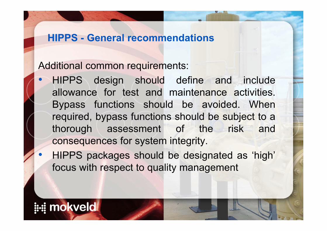
HIPPS - General recommendations
Additional common requirements:• HIPPS should execute all safety functions in
automatic mode.• HIPPS should be autonomous, with dedicated
sensors, logic and final elements.• HIPPS should be a physically segregated
system, interfaced with the facility automationsystem for monitoring only. Any communicationswith HIPPS should not be able to impede oroverride the safety function(s).

HIPPS - General recommendations
Additional common requirements:• HIPPS should be designed according to fail-to-
safe principles.• Resetting should not be possible without a clear
understanding of the initiating cause and/or fault(eg. Manual reset on SOVs)
• Signals between sensors, logic solver and finalelements should be hardwired.
HIPPS - General recommendations
Additional common requirements:• HIPPS design should define and include
allowance for test and maintenance activities.Bypass functions should be avoided. Whenrequired, bypass functions should be subject to athorough assessment of the risk andconsequences for system integrity.
• HIPPS packages should be designated as ‘high’focus with respect to quality management

HIPPS - General recommendations
Additional common requirements:• HIPPS design should consider the full safety life
cycle.• As component age the probability of
failure increases.• The component(s) lifetime
depends on the test frequency and ability to detect dangerous failure
• Less reliable systems will therefore require higher test frequencies to suit same SIL requirement!
Probability of Failure on DemandSingle Mokveld configuration
1,E-05
1,E-04
1,E-03
0 1 2 3 4
Proof Test Interval [hours104]
Prob
abilit
y [-]

HIPPS - Reliability Criteria
HIPPS components, including sensors, logic solverand final elements should each be designed asfail-safe (i.e. failure of any component/sensor/logic solver/power supply/motive fluidsmoves final elements to the safe state).

HIPPS SRS
PDFavg or failure rate
HIPPS - Reliability Criteria
HIPPS components or sub-systems are thenselected such that the overall integrity (SIL) targetof the HIPPS Safety Instrumented Function (SIF)is achieved.
SIL assessment
IEC 61511
PFDsis = PFDI + PFDLS + PFDSOV + PFDSDV
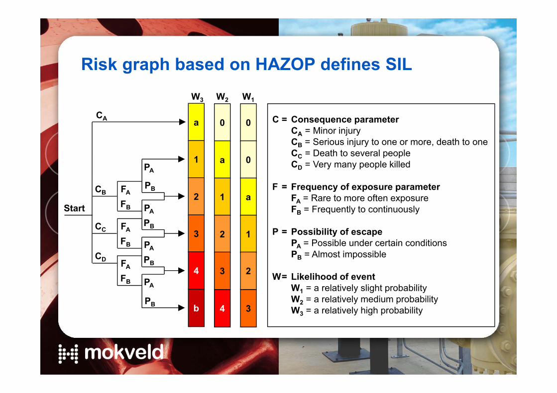
Risk graph based on HAZOP defines SIL
C = Consequence parameterCA = Minor injuryCB = Serious injury to one or more, death to oneCC = Death to several peopleCD = Very many people killed
F = Frequency of exposure parameterFA = Rare to more often exposureFB = Frequently to continuously
P = Possibility of escapePA = Possible under certain conditionsPB = Almost impossible
W= Likelihood of eventW1 = a relatively slight probabilityW2 = a relatively medium probabilityW3 = a relatively high probability
Start
a
W3 W2 W1
CA
CB
CD
FA
CC FA
FB
FB
FA
FB
PA
PB
PA
PB
PA
PB
PA
PB
1
2
3
b
4
0
a
1
2
4
3
0
0
a
1
3
2

SIL required defines the design of safety loop
Safety Integrity Level
Probability of Failure on Demand Risk Reduction Factor
SIL PFD RRF
0 No safety requirements (at all)
a No special safety requirements (e.g. only a procedure)
1 ≥10-2 to <10-1 > 10 to ≤ 100
2 ≥10-3 to <10-2 > 100 to ≤ 1.000
3 ≥10-4 to <10-3 > 1.000 to ≤ 10.000
4 ≥10-5 to <10-4 > 10.000 or better
b A single safety system is not sufficient (even with redundant components)

PFD2,7x10-4
PFD2,7x10-4
PT1 &PT2FAILS
PT1FAILS
PT2FAILS
PFD PT11,3x10-4
PFDInput card 11,4x10⁻⁴
PFD TF21,3x10-4
PFDInput card 21,4x10⁻⁴
PFD2,7x10-4
PFD2,7x10-4
PT1 &PT3FAILS
PT1FAILS
PT3FAILS
PFD PT11,3x10-4
PFDInput card 11,4x10⁻⁴
PFD PT31,3x10-4
PFDInput card 31,4x10⁻⁴
PFD2,7x10-4
PFD2,7x10-4
PT2 &PT3FAILS
PT2FAILS
PT3FAILS
PFD PT21,3x10-4
PFDInput card 21,4x10⁻⁴
PFD PT31,3x10-4
PFDInput card 31,4x10⁻⁴
2oo3
PROSAFEController (AK7)PFD 5x10⁻⁷
PFD for 2oo3Voting PT2,2x10-7
CCF: PT’s2,7x10-5
CCF: FE’s2,3x10-4
CCF: SOL’s1,0x10-4
MOKVELD HIPPSPFD 3,65x10⁻⁴
PFDSolenoid1,0x10-3
PFDSolenoid1,0x10-3
PFDSolenoid1,0x10-3
PFDSolenoid1,0x10-3
1oo21,0x10-6
1oo21,0x10-6
PFDFinal Element2,3x10-3
PFDFinal Element2,3x10-3
2nd FE1st FE
1oo2
PFD 2nd FE2,3x10-3
PFD 1st FE2,3x10-3
PFD for combination of 2 sequential FE’s5,5x10-6
Fault tree analyses HIPPS

HIPPS - Reliability Data
The HIPPS operator should approve the reliability datautilized to demonstrate the integrity achieved by theHIPPS. Reliability data sources include, in order ofpreference:
1. Field data – but only where the quantity collected is sufficientto be considered statistically significant
See 7.4.10.4 : A proven in use safety justification shall bedocumented that the element supports the required safetyfunction with the required systematic safety integrity. This shallinclude: the suitability analysis and testing of the element for theintended application and the demonstration of equivalencebetween the intended operation and the previous operationexperience, including the impact analysis on the differences

Database filled since 70‘s
Introduction into HIPPS E L2 R0 slide 30
Each after-sales related action entered in database
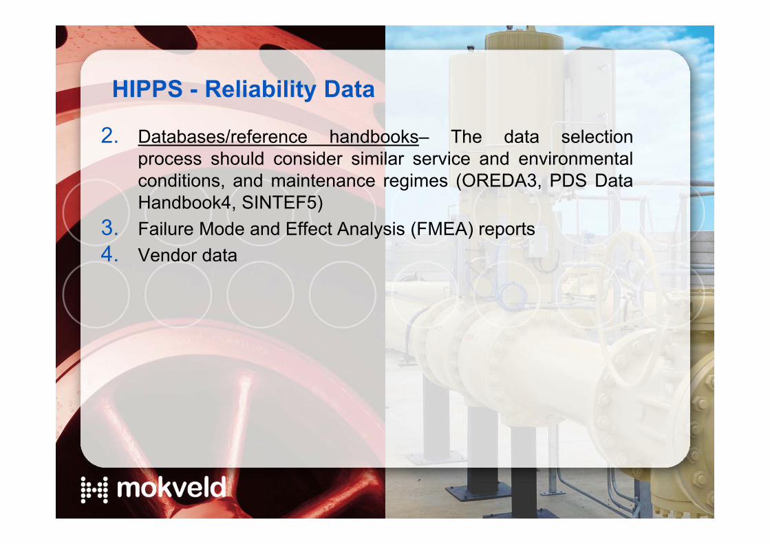
HIPPS - Reliability Data
2. Databases/reference handbooks– The data selectionprocess should consider similar service and environmentalconditions, and maintenance regimes (OREDA3, PDS DataHandbook4, SINTEF5)
3. Failure Mode and Effect Analysis (FMEA) reports4. Vendor data

• Architecture to be verified• Failure rates shall be dependable or “proven in use”:
• Based on field experience in same application• For same stroking time (< 2 sec.)
• Integrated FAT & SAT
PFD / SIL of complete safety loop to be verified
Wellhead
Choke
Small thermal SRV
Wing valve
ANSI 1500 ANSI 600Liquid out
Gas out
Separation
PT PT PT
Voting logic: closes final elementsin case of high pressure at 2oo3 PT
InitiatorsFinal elements

Example in Europe
Location : Gasunie Netherlands BBL Balgzand pipelineSpecs : 2 x 1oo2 Electronic HIPPS protecting ANSI 600 control
valves against pressure from ANSI 900 compressor
Introduction into HIPPS E L2 R0 slide 35

Example in Europe
Location : NAM Netherlands mobile production unitSpecs : 1oo2 Mechanical HIPPS protecting ANSI 900
pipeline against pressure from ANSI 2500 wellhead
Introduction into HIPPS E L2 R0 slide 36

Example in Europe
Location : Dong Denmark NybroSpecs : 1oo2 Electronic HIPPS protecting ANSI 600 onshore
installation against pressure from ANSI 900 pipeline
Introduction into HIPPS E L2 R0 slide 37

Example in Europe
Location : Statoil Germany Zeepipe landfall Specs : 1oo2 Mechanical HIPPS protecting ANSI 600 onshore
installation against pressure from ANSI 900 pipeline
Introduction into HIPPS E L2 R0 slide 38

We thank you for your attention