insulation and monitoring system for pure electric vehicle ...journal.it.cas.cz/62(2017)-1b/paper 03...
TRANSCRIPT

Acta Technica 62 No. 2C/2017, 23–34 c© 2017 Institute of Thermomechanics CAS, v.v.i.
Insulation and monitoring system forpure electric vehicle based on
microcontroller unit
Han Peng1
Abstract. The purpose of this paper is to study insulation and monitoring system of pureelectric vehicle. By insulating the performance decline of insulated wires, it is proved that pure elec-tric vehicle based on micro controller unit will lead to serious consequence. The insulation detectingmethods is used in the market to put forward an improved detecting method. Its characteristicrefers to utilizing the bias resistance to detect insulation, while the main control chip providessignals to control the bias resistance. In the end, the peripheral circuit was designed centered onAdvanced RISC Machine (ARM) micro controller unit (MCU for short). Modular programmingis adopted to simplify the programming process. The experimental results show the accuracy andreliability of the insulation detection system by constructing an experimental platform. In theverification experiment, the insulation resistance is measured and its value with theoretical value100 kΩ is compared. The relative error is only 0.173%, and the standard deviation is 3.70. Theinsulation detecting system of pure electric vehicle designed this time is of certain accuracy andfeasibility. Based on the the above finding, it is concluded that the design of insulation detectionsystem is suitable for pure electric vehicle based on micro controller unit.
Key words. Micro controller unit, pure electric vehicle, insulation detecting system, maincontrol chip.
1. Introduction
Environmental pollution caused by the fuel vehicles exhaust is becoming moreand more severe owing to the increasingly expanding of automobile market. Facedwith the existing energy-environment problems, the research, development and pro-motion of high-efficient clean electric vehicle are becoming an irresistible trend inautomotive field [1]. However, most cars are fuel-powered, so they are free from thedisasters caused by insulation. On the contrast, electric vehicle is electric-driven. Toensure enough power, there is always a high-voltage power supply assembled in thevehicle [2]. In the high voltage circuit of electric car, high-voltage and low-resistance
1School of Mechanical Engineering, North China University of Water Resource and ElectricPower, 450045, China
http://journal.it.cas.cz

24 HAN PENG
will form heavy current. Therefore, the battery voltage pf high voltage side of theelectric vehicle should remain high-voltage (about 300V). In addition, the positiveand negative pole of the high-voltage battery are connected on the ends of the insu-lated wire, whose resistance is very low, so transient current of the high-voltage sideloop will be very heavy [3].
As a result, the quality of the insulation system of the electric vehicle is of highimportance. Insulation aging of the high-voltage side will pose a threat to driverseven the security of passengers.
2. Materials and methods
2.1. Design of insulation detecting system
Power system is very important to the electric car. Particular electric devices areschematically shown in Fig. 1. The requirements to voltage is different in differentplaces, and meanwhile the high and low voltage side power system appeared [4].High-voltage power system consists of four parts and drives the operation of highpower devices like motor [5]. While the low-voltage power system supplies electricto electric devices, in order to avoid electric leakage and other issues. We emphasison the high-voltage electric system in this research.
Fig. 1. Electric devices of electric vehicle
At present, the frequently used insulation detecting methods have bus end volt-age method, AC signals injection method and DC voltage insulation measurementmethod [6]. The circuit used in bus end voltage method is simple but of unreliability,cannot influence fault like short circuit to ground. AC signals injection method refersto injecting AC signals in the DC system of the high-voltage side of electric vehicle,comparing, calculating and working out the insulation condition of the monitoringsystem. DC voltage insulation measurement method is realized by measuring theinsulated resistance. Mosfet tube is used in the switch, so it is unavoidable for the

INSULATION AND MONITORING SYSTEM 25
high current signals to produce some disturbing signals during the measuring. Thiswill influence on the calculating accuracy [7].
2.2. Insulation detecting method
The insulation condition of electric vehicle is measured by the insulated resis-tance of DC positive and negative bus to the earth, according to the regulationsof BS ISO 6469-1-2009: divide nominal voltage U of electric vehicle DC system byinsulation resistance value, the result greater than 100 Ω/V conforms with the secu-rity requirement, the result lower than this value shows the insulation fault of pureelectric vehicle [8].
The principle of measurement is shown in Fig. 2, in which, Vb is the storagebattery voltage, Rp and Rn are the insulation resistances of the positive bus andnegative bus on the earth, respectively. The exterior of the short dash box is themonitoring circuit model of the insulated resistance of the pure electric vehicle, inwhich R0 is the nominal bias resistance, R0, S1, S2 construct a bias resistancenetwork. R1 and R2, R3 and R4 construct the measurement voltage division circuit,Vp and Vn represent the voltages of positive pole and negative pole to the earth,respectively. During measuring, turn off S1 and S2, and draw Vp and Vn. And thenaccording to the values of Vp and Vn, judge whether R0 is in parallel with Rp or inseries with Rn.
Fig. 2. Schematic circuit diagram of insulation detecting
If Vp > Vn, turn off S1 and disconnect S2, then we can measure the voltage valueof the positive and negative buses to earth V ′
p and V ′n. According to the circuitous
principle, we can work out the calculating formula of insulation resistance Ri of the
26 HAN PENG
DC high-voltage system:
Vp
Rp=
Vn
Rn,
V ′p
Rp//R0=
Vn
Rn. (1)
Now we can draw that
Rn = R0
(VpV
′n
V ′pVn
− 1
). (2)
As Vp > Vn, then Rp ≥ Rn. Therefore, choose the lower resistance Rn as Ri.For the same reason, when Vp < Vn, the relative insulation resistance can be workedout.
3. Hardware design
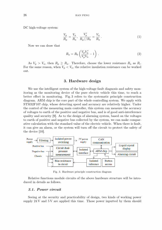
We use the intelligent system of the high-voltage fault diagnosis and safety mon-itoring as the monitoring device of the pure electric vehicle this time, to reach abetter effect in monitoring. Fig. 3 refers to the systematic principle constructiondiagram. ARM chip is the core part of the whole controlling system. We apply withSTM32F107 chip, whose detecting speed and accuracy are relatively higher. Underthe control of the measuring main controller, this system can measure the accuracyof voltages to earth of the positive and negative bus, and is of good anti-interferencequality and security [9]. As to the design of alarming system, based on the voltagesto earth of positive and negative bus collected by the system, we can make compar-ative calculation with the standard value of the electric vehicle. When there is fault,it can give an alarm, or the system will turn off the circuit to protect the safety ofthe device [10].
Fig. 3. Hardware principle construction diagram
Relative functions module circuits of the above hardware structure will be intro-duced in details as follows.
3.1. Power circuit
Seeing at the security and practicability of design, two kinds of working powersupply 24V and 5V are applied this time. Those power inputted by them should

INSULATION AND MONITORING SYSTEM 27
be under relative protections like filtering and reversed connection-avoidance. Pureelectric vehicle uses DC 24V, so we designed the 5V power circuit and switch itwith the 24V power circuit [11].
3.2. Measuring circuit
When the electric vehicle is moving, the insulation detecting environment will beworse, thus the voltage of insulated end is high and unstable [12]. Voltage measuredby STM32 is only several VA, so we apply TE6664N chip to construct the measuringcircuit, using two circuits in measuring, one for collecting the voltages betweenground wire and positive bus, the other one for collecting voltages between negativebus and ground wire. Moreover, high-pressure optronic relay can be used to controlhigh-voltage circuit and the bias resistance access circuit. The voltages decreasedafter the signals pass the multilevel voltage division resistor [13].
3.3. Bias resistance access circuit
Figure 4 represents the schematic diagram of the access circuit of bias resistanceR0. C_Detect+ and C_Detect- is from the controlling signals of STM32, and isequal to switch S1 and S2 in the schematic diagram. SGIELD is the ground wire,and U2 and U3 is optronics, playing the role of insulating to raise the stability ofcircuits. The resistance connected with the right end of optronics is bias resistanceR0. Controlling signals output by the STM32 control R0 by controlling the conti-nuity of U2 and U3, it can decide whether connecting R0 with the circuit of positivebus to the ground or with the negative one [14].
Fig. 4. Schematic diagram of bias resistance access circuit( BAT+ and BAT- referto the positive bus end and negative bus end of the power storage battery
respectively)

28 HAN PENG
3.4. Protective circuit
The voltage of storage battery cannot be too high or too low [15], so we mustadopt high-voltage and low-voltage protective circuit (see Fig. 5). Safe voltage valuerange of storage batteries is 150∼300V. The system should be designed including aspecific function to detect the voltages of the two ends of the storage battery. Whenthe signals have not been fed back to the system, the alarm will be given to reachreal-time process.
Fig. 5. Protective circuit
3.5. High-voltage loop inter-lock circuit
The reliability of high-voltage loop is of great significance. To better detect theintegrity of the high-voltage power-supply loop, we show the high-voltage inter-lockdetecting loop in Fig. 6. In the fig, the on-off condition of Q6 is controlled by thecontrolling signals given by the high-voltage loop inter-lock of the main controllingchip. It controls Mosfet tube to control the on-off of 5V voltage signals. 5V voltagein the circuit is supplied by the power circuit of the monitoring system, and isinputted in the high-voltage loop J1 to force the return voltage to be detected intime. If the voltage detecting system has not received the return signals, high-voltageloop inter-lock will recognize the fault, and then the circuit will give an alarm andat the same time, it will turn off itself automatically.
Fig. 6. Schematic diagram of high-voltage loop inter-lock circuit
In this system, there are also temperature measurement circuit of the powerstorage batteries( adopting DS18B20 sensor), circuit design of liquid crystal display

INSULATION AND MONITORING SYSTEM 29
(2.8-cun, 16-bits TFT LCD, 320×240 resolution ratio), and CAN communicationcircuit (applying with module TD301DCAN) (not covered here).
Moreover, we also design the anti-interference quality and operating managingof the hardware. In the field of pure electric vehicle, high-voltage DC system wasseen as strong electromagnetic interference. Therefore, its anti-interference qualitywill be set as a standard, whose value largely decides the reliability of the electricparameter, and also plays a vital role in the operating of the system. During theoperating of high-voltage system, there are two levels of fault: minor fault and majorfault, which is called class one failure and class two failure in software respectively.Fault in high-voltage loop belongs to class one, and fault in insulation resistancerefers to class two. Faults resulted from the high temperature of power storagesupply can be defined to class one failure and class two failure according to theextent of damages.
4. Software design
The core of control section of this research is STM32F107. Form a completeset of software by invoking firmware library to control each function module, thusto realize the monitoring to the insulation system, and at the same time, realizethe functions of relay, PWM signals control, alarm display, CAN communication,sampling measurement controlling, insulated resistance calculating and so on. Inthis way, the principle of active insulation monitoring is realized. We can drawthe resistance values of the positive and negative insulated resistance with relevantcalculating method.
We adopts Keil uvision3 as the software development platform, and realize theprogramming of STM32F107 by invoking firmware library. The operating environ-ment of the pure electric vehicle is complicated, so we add some protective circuitsand anti-interference measurements to reinforce the reliability of the system, suchas digital filtering technology and “watchdog” technique. The flow chart of mainsystematic program is shown in Fig. 7.
There are twice sampling of AD needed to be done, sampling two data signalsevery time, thus to draw the insulated resistance value. The first sampling is biasresistance and will not be involved in the whole system. Collect two data signals atthe second time, work out the insulated resistance value of the bus insulated wire.The flow chart of AD sampling is in Fig. 8.
Fig. 9 refers to light alarm system. The positive and negative insulated resistancevalue calculated above is the condition to judge the light alarm condition. Figure10 shows the flow chart of operating managing and disconnecting controlling, whenin failure.
The pure electric vehicle may suffer from faults no matter in the starting, op-erating and parking process. When encountering fault, the monitoring system ofhigh-voltage electricity will be access to the control strategy of disconnecting whenin failure, thus to turn off the high-voltage loop.
During the reliability design and optimization of the systematic software, con-cerning with the functions needed to be realized as well as the whole process, the

30 HAN PENG
Fig. 7. Flow chart of main systematic program
linkage process of every motion must be fluent and natural during the whole in-sulation detecting. So we use optional structure “Switch” in the complete system.The connections between every action statement is accomplished by its multi-branchstatements. All in all, frequently used modular programming method used in thistime makes a higher systematic readability.
Fig. 8. Flow chart of AD sampling

INSULATION AND MONITORING SYSTEM 31
Fig. 9. Light alarm program
Fig. 10. Flow chart of operating managing and disconnecting controlling when infailure
5. Results
To judge the insulation condition of the insulated system, we construct the systemtest platform. The test platform constructed for the high-voltage safety test systemof pure electric vehicle includes: 200V high-voltage DC supply, 24V DC supply,oscilloscope, multimeter, safety monitoring system, etc.
To ensure rationality and comprehensiveness of the test, our testing sequenceis from partial to the whole, i.e. debugging software first and then the hardware,

32 HAN PENG
debugging the low-voltage environment first and then the high-voltage.these are allthe sequences to conduct test. The test results of insulated resistance value areshown in Table 1.
Table 1. Test results of insulated resistance value (kΩ)
No.1 No.3 No.4 No.5 No.6 No.7 No.8 No.9 No.10 Averagevalue
Measuredvalue
97 98 98 101 99 100 97 98 102 99.1
Standardvalue
Error –3 –2 –2 1 –1 0 –3 –2 2
The standard value is:
S =
√∑ni=1(si − s)2
n=
=
√32 + 1 + 22 + 22 + 1 + 1 + 0 + 32 + 22 + 22
10kΩ = 3.70 kΩ .
Seeing the results in Table 1 and comparing the measured value of insulatedresistance with theoretical value 100 kΩ, we can draw that the relative error is only0.173%, and the standard deviation is 3.70. This is persuasive enough to provethe accuracy of the calculating module of the insulated resistance designed in thisresearch.
6. Conclusion
We designed a detecting system based on ARM MCU directing at high voltagecircuit safety monitoring on pure electric vehicle, and tested the feasibility of it. Themain research process and result are as follows:
To put forward an improved insulation detection method concerning with thereasons why the high voltage side of electric vehicle need insulation detecting andalso referring with the existing detecting methods in the market.
To design the schematics of many aspects like interposing the bias resistance,insulation detecting, high and low voltage protection, high voltage loop interlock-ing according to the principle of voltage detection. To show the whole hardwarestructure of the system. To compile a program that can realize the relative func-tions of hardware electric circuit based on Keil uVision 3 as the software developingplatform, as well as the modular principles.
To construct the testing platform, and testify the feasibility and reliability of thistheory and method.

INSULATION AND MONITORING SYSTEM 33
References
[1] H.M.Vasquez, M.Kuttner: System and method for monitoring an electri-cal device. Patent US9172233, Assignee: Early Rescue Solutions, LLC, Inventors:M.H.Vasquez, M.Kuttner (2015).
[2] D.U.Yong, Q. Si: Application of harmonic electric field method to ±800 kV UHVDC composite insulator on-line detection. High Voltage Engineering 38 (2012), No. 02,382–386.
[3] C. Zhou, S.Hu, W. Sha, Q. Liu, X.Yu: Active detection system of insulation re-sistance in electric vehicle. Journal of Electronic Measurement and Instrumentation27 (2013), No. 05, 409–414.
[4] Y.Du, R.Ding: Detection of traffic sound for driving safety: Effects of car bodysound insulation. Noise Control Engineering Journal 62 (2014), No. 6, 436–448.
[5] P.Fabian, M.Haynes, H.Babcock, M.Hooker: Characterization and qualifica-tion of cyanate ester/epoxy insulation for NSTX-U fusion magnets. IEEE Transactionson Applied Superconductivity 23 (2013), No. 3, paper 7700204.
[6] B.Dong, Y.T.Tian, C. J. Zhou: Fuzzy logic-based optimal control method for en-ergy management of pure electric vehicle. Journal of Jilin University (Engineering andTechnology Edition) 45 (2015), No. 2, 516–525.
[7] J.Yang, Z. Zeng, Y.Tang, J.Yan, H.He, Y.Wu: Load frequency control in iso-lated micro-grid with electrical vehicle based on multivariable generalized predictivetheory. Energies 8 (2015), No. 3, 2145–2164.
[8] D.T.Qin, M.Y.Yao, S. J. Chen, S.K. Lyu: Shifting process control for two-speedautomated mechanical transmission of pure electric vehicles. International Journal ofPrecision Engineering and Manufacturing 17 (2016), No. 5, 623–629.
[9] P.Yu, T. Zhang, X.H.Wang, R.Guo: Surge analysis and active-passive controlfor a central driven pure electric vehicle. Journal of Vibration and Shock 34 (2015),No. 13, 53–59, 65.
[10] Y.H.Hung, Y.X. Lin, C.H.Wu, S. Z. Chen: Mechatronics design and experimen-tal verification of an electric-vehicle-based hybrid thermal management system. Ad-vances in Mechanical Engineering 8, (2016), No. 2, 1–9.
[11] F.Machado, J. P. F.Trovão, C.H.Antunes: Effectiveness of supercapacitors inpure electric vehicles using a hybrid metaheuristic approach. IEEE Transactions onVehicular Technology 65 (2015), No. 1, 29–36.
[12] D. Savitski, V. Ivanov, B. Shyrokau, J.D. Smet, J. Theunissen: Experimentalstudy on continuous abs operation in pure regenerative mode for full electric vehicle.SAE International Journal of Passenger Cars - Mechanical Systems 8 (2015), No. 1,364–369.
[13] F.Chen, Y. Sun, C. Zhao, J.Yang, H.Ye, J. Zhu, Q.Tang: Elastic pipeline de-sign of high performance micro-controller YL8MCU for signal processing of digitalhome appliances. Open Automation and Control Systems Journal 7 (2015), No. 1,863–872.
[14] S.M.Kumar, V.K.Gobinath, D.R. P.Rajarathnam, D. Jayanth,P. S.Kumar, D.Nandagopal: Automatic LID controller for laptop using micro-controller. International Journal of Applied Engineering Research 10 (2015), No. 93,261–263.
[15] G.M.Ma, Z.Wu, H.Y. Zhou, J. Jiang, W.X.Chen, S. S. Zheng, C.R. Li,X. Li: A wireless and passive on-line temperature monitoring system for GIS basedon surface acoustic wave sensor. IEEE Transactions on Power Delivery 31 (2016),No. 3, 1270–1279.
Received June 29, 2017

34 HAN PENG