insulation and refractory basics by v.p.singh
TRANSCRIPT

INSULATION
AND
REFRACTORY
by
V.P. Singh

CONTENT
• Refractory-
– Types,
– Selection
– Application of Refractoriness.
• Insulation
– Type
– Application,
– Economic Thickness of Insulation,
– Heat Savings and Application Criteria,

INSULATION
• A thermal insulator is a poor conductor of heat and has a low thermal
conductivity. Insulation is used in buildings and in manufacturing
processes to prevent heat loss or heat gain. Although its primary purpose
is an economic one, it also provides more accurate control of process
temperatures and protection of personnel. It prevents condensation on
cold surfaces and the resulting corrosion. Such materials are porous,
containing large number of dormant air cells.
• Thermal insulation delivers the following benefits:
– Reduces over-all energy consumption
– Offers better process control by maintaining process temperature.
– Prevents corrosion by keeping the exposed surface of a refrigerated system
above dew point
– Provides fire protection to equipment
– Absorbs vibration

INSULATION- Types and Application
• The Insulation can be classified into three groups according to thetemperature ranges for which they are used.
• Low Temperature Insulations (up to 90 °C)
• This range covers insulating materials for refrigerators, cold and hot watersystems, storage tanks, etc. The commonly used materials are Cork, Wood,85% magnesia, Mineral Fibers, Polyurethane and expanded Polystyrene,etc.
• Medium Temperature Insulations (90 – 325 °C)
• Insulators in this range are used in low temperature, heating and steamraising equipment, steam lines, flue ducts etc. The types of materials usedin this temperatures range include 85% Magnesia, Asbestos, CalciumSilicate and Mineral Fibers etc.
• High Temperature Insulations (325 °C – above )
• Typical uses of such materials are super heated steam system, oven dryerand furnaces etc. The most extensively used materials in this range areAsbestos, Calcium Silicate, Mineral Fibre, Mica and Vermiculite basedinsulation, Fireclay or Silica based insulation and Ceramic Fibre.
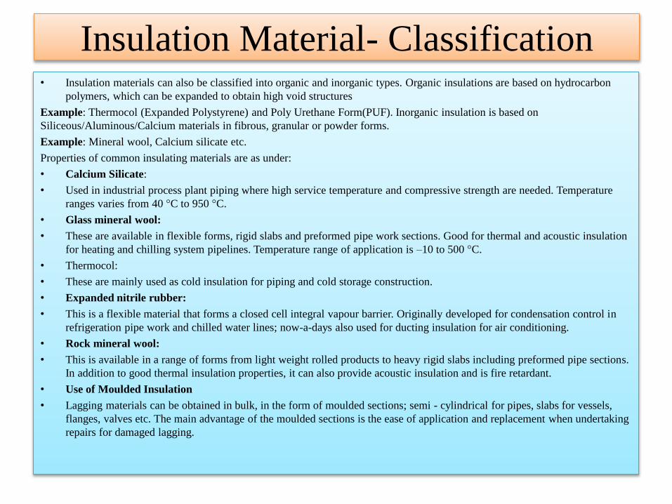
Insulation Material- Classification• Insulation materials can also be classified into organic and inorganic types. Organic insulations are based on hydrocarbon
polymers, which can be expanded to obtain high void structures
Example: Thermocol (Expanded Polystyrene) and Poly Urethane Form(PUF). Inorganic insulation is based on
Siliceous/Aluminous/Calcium materials in fibrous, granular or powder forms.
Example: Mineral wool, Calcium silicate etc.
Properties of common insulating materials are as under:
• Calcium Silicate:
• Used in industrial process plant piping where high service temperature and compressive strength are needed. Temperature
ranges varies from 40 °C to 950 °C.
• Glass mineral wool:
• These are available in flexible forms, rigid slabs and preformed pipe work sections. Good for thermal and acoustic insulation
for heating and chilling system pipelines. Temperature range of application is –10 to 500 °C.
• Thermocol:
• These are mainly used as cold insulation for piping and cold storage construction.
• Expanded nitrile rubber:
• This is a flexible material that forms a closed cell integral vapour barrier. Originally developed for condensation control in
refrigeration pipe work and chilled water lines; now-a-days also used for ducting insulation for air conditioning.
• Rock mineral wool:
• This is available in a range of forms from light weight rolled products to heavy rigid slabs including preformed pipe sections.
In addition to good thermal insulation properties, it can also provide acoustic insulation and is fire retardant.
• Use of Moulded Insulation
• Lagging materials can be obtained in bulk, in the form of moulded sections; semi - cylindrical for pipes, slabs for vessels,
flanges, valves etc. The main advantage of the moulded sections is the ease of application and replacement when undertaking
repairs for damaged lagging.

Thermal conductivities of typical hot and cold
insulation materials

Calculation of Insulation Thickness
• The most basic model for insulation on a pipe is shown in Figure 5.2. r1 show the outside
radius of the pipe r2 shows the radius of the Pipe+ insulation.
• Heat loss from a surface is expressed as
• H = h X A x (Th–Ta)
• Where
• h = Heat transfer coefficient, W/m2–K
• H = Heat loss, Wattsantage of the moulded sections is the ease of application and replacement
when undertaking repairs for damaged lagging.
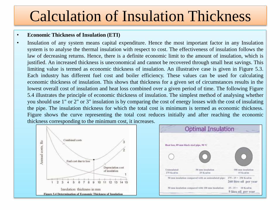
Calculation of Insulation Thickness• Economic Thickness of Insulation (ETI)
• Insulation of any system means capital expenditure. Hence the most important factor in any Insulation
system is to analyse the thermal insulation with respect to cost. The effectiveness of insulation follows the
law of decreasing returns. Hence, there is a definite economic limit to the amount of insulation, which is
justified. An increased thickness is uneconomical and cannot be recovered through small heat savings. This
limiting value is termed as economic thickness of insulation. An illustrative case is given in Figure 5.3.
Each industry has different fuel cost and boiler efficiency. These values can be used for calculating
economic thickness of insulation. This shows that thickness for a given set of circumstances results in the
lowest overall cost of insulation and heat loss combined over a given period of time. The following Figure
5.4 illustrates the principle of economic thickness of insulation. The simplest method of analysing whether
you should use 1" or 2" or 3" insulation is by comparing the cost of energy losses with the cost of insulating
the pipe. The insulation thickness for which the total cost is minimum is termed as economic thickness.
Figure shows the curve representing the total cost reduces initially and after reaching the economic
thickness corresponding to the minimum cost, it increases.
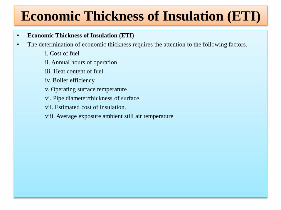
Economic Thickness of Insulation (ETI)
• Economic Thickness of Insulation (ETI)
• The determination of economic thickness requires the attention to the following factors.
i. Cost of fuel
ii. Annual hours of operation
iii. Heat content of fuel
iv. Boiler efficiency
v. Operating surface temperature
vi. Pipe diameter/thickness of surface
vii. Estimated cost of insulation.
viii. Average exposure ambient still air temperature

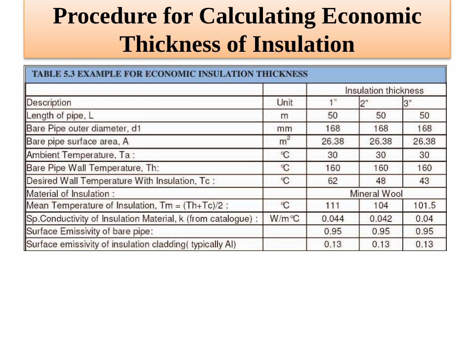
Procedure for Calculating E.T. of Insulation
• To explain the concept of economic thickness of insulation, we will use an example. Consider an 8 bar steam pipeline of 6"
dia having 50-meter length. We will evaluate the cost of energy losses when we use 1", 2" and 3" insulation to find out the
most economic thickness.
• A step-by-step procedure is given below.
• 1. Establish the bare pipe surface temperature, by measurement.
• 2. Note the dimensions such as diameter, length & surface area of the pipe section under consideration.
• 3. Assume an average ambient temperature. Here, we have taken 30 °C.
• 4. Since we are doing the calculations for commercially available insulation thickness, some trial and error calculations will
be required for deciding the surface temperature after putting insulation. To begin with assume a value between 55 & 65 °C,
which is a safe, touch temperature.
• 5. Select an insulation material, with known thermal conductivity values in the mean insulation temperature range. Here the
mean temperature is 111 °C. and the value of k = 0.044 W/m2°C for mineral wool.
• 6. Calculate surface heat transfer coefficients of bare and insulated surfaces, using equations discussed previously. Calculate
the thermal resistance and thickness of insulation.
• 7. Select r2 such that the equivalent thickness of insulation of pipe equals to the insulation thickness estimated in step 6.
From this value, calculate the radial thickness of pipe insulation = r2-r1
• 8. Adjust the desired surface temperature values so that the thickness of insulation is close to the standard value of 1" ( 25.4
mm).
• 9. Estimate the surface area of the pipe with different insulation thickness and calculate
• the total heat loss from the surfaces using heat transfer coefficient, temperature difference between pipe surface and ambient.
• 10. Estimate the cost of energy losses in the 3 scenarios. Calculate the Net Present Value of the future energy costs during an
insulation life of typically 5 years.
• 11. Find out the total cost of putting insulation on the pipe ( material + labor cost)
• 12. Calculate the total cost of energy costs and insulation for 3 situations.
• 13. Insulation thickness corresponding to the lowest total cost will be the economic thickness of insulation.
Procedure for Calculating Economic
Thickness of Insulation

Procedure for Calculating Economic
Thickness of Insulation

Procedure for Calculating Economic
Thickness of Insulation
Note: the total cost is lower when using 2" insulation, hence is the economic insulation
thickness.
INTRODUCTION
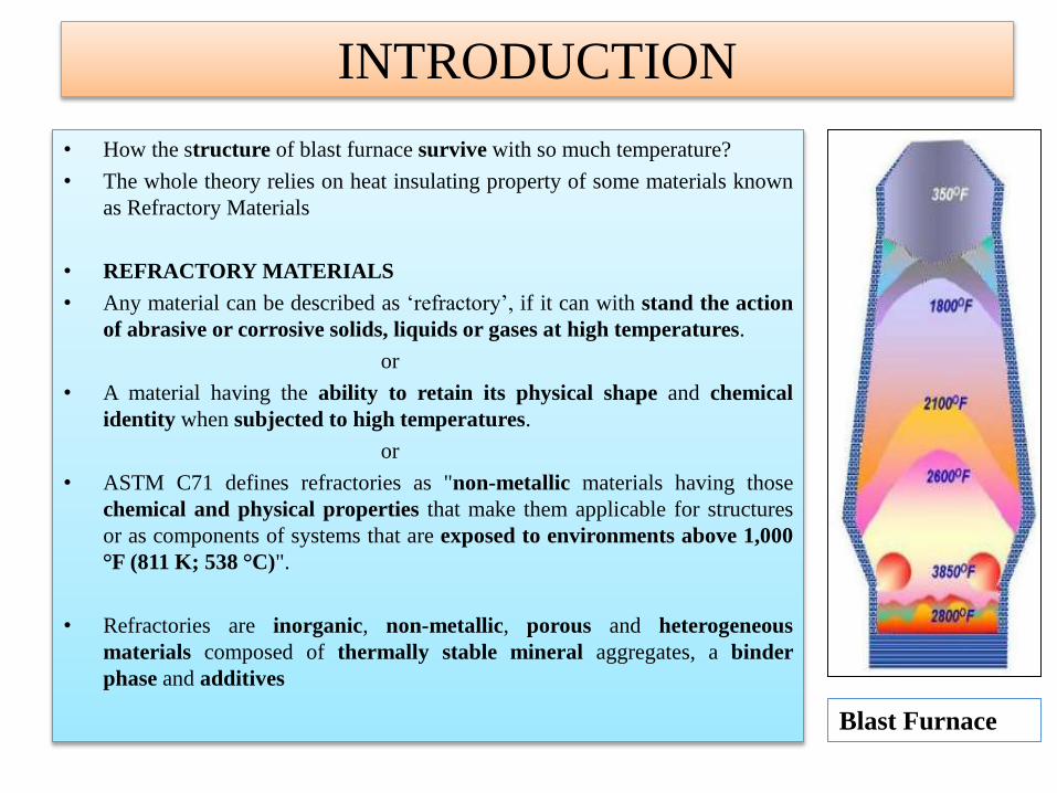
• How the structure of blast furnace survive with so much temperature?
• The whole theory relies on heat insulating property of some materials known
as Refractory Materials
• REFRACTORY MATERIALS
• Any material can be described as ‘refractory’, if it can with stand the action
of abrasive or corrosive solids, liquids or gases at high temperatures.
or
• A material having the ability to retain its physical shape and chemical
identity when subjected to high temperatures.
or
• ASTM C71 defines refractories as "non-metallic materials having those
chemical and physical properties that make them applicable for structures
or as components of systems that are exposed to environments above 1,000
°F (811 K; 538 °C)".
• Refractories are inorganic, non-metallic, porous and heterogeneous
materials composed of thermally stable mineral aggregates, a binder
phase and additives
Blast Furnace

REFRACTORIES
• A refractory material is one that retains its strength at hightemperatures. ASTM C71 defines refractories as "non-metallic materials having those chemical and physicalproperties that make them applicable for structures, or ascomponents of systems, that are exposed to environmentsabove 1,000 °F (811 K; 538 °C)".
• Refractory materials are used in linings for furnaces, kilns,incinerators and reactors. They are also used to makecrucibles and moulds for casting glass and metals and forsurfacing flame deflector systems for rocket launch structures.
• Today, the iron- and steel-industry uses approximately 70% ofall refractories produced.
THE GENERAL REQUIREMENTS OF A
REFRACTORY MATERIAL
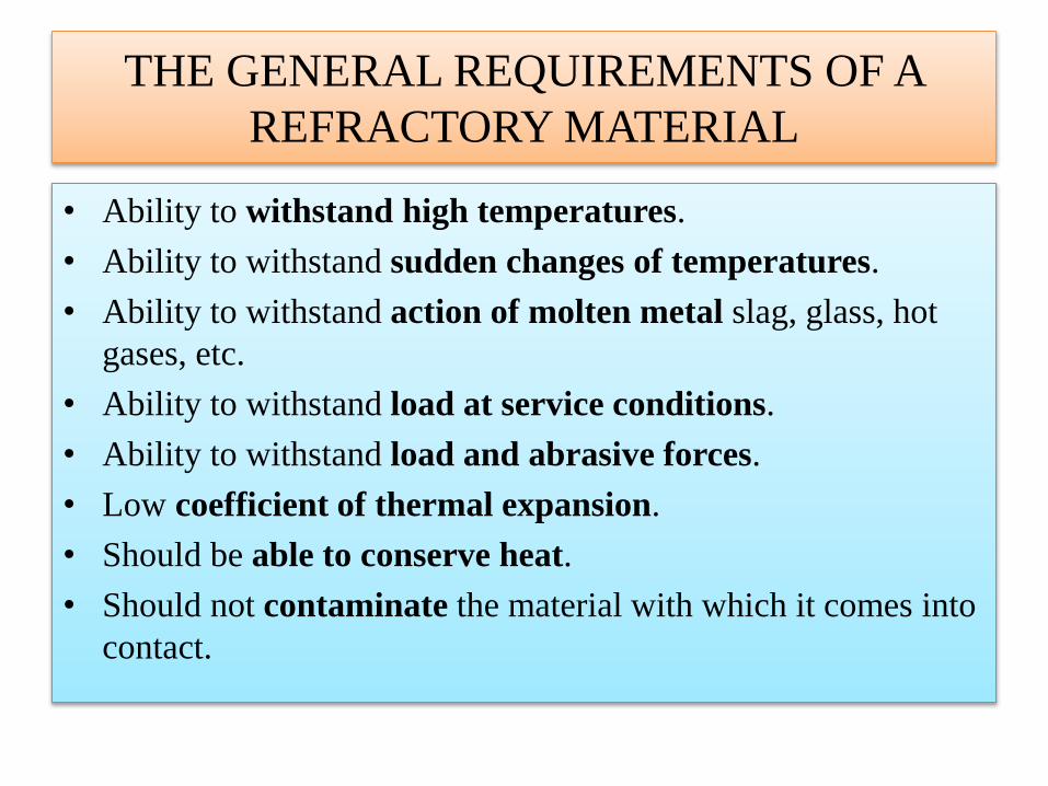
• Ability to withstand high temperatures.
• Ability to withstand sudden changes of temperatures.
• Ability to withstand action of molten metal slag, glass, hot
gases, etc.
• Ability to withstand load at service conditions.
• Ability to withstand load and abrasive forces.
• Low coefficient of thermal expansion.
• Should be able to conserve heat.
• Should not contaminate the material with which it comes into
contact.
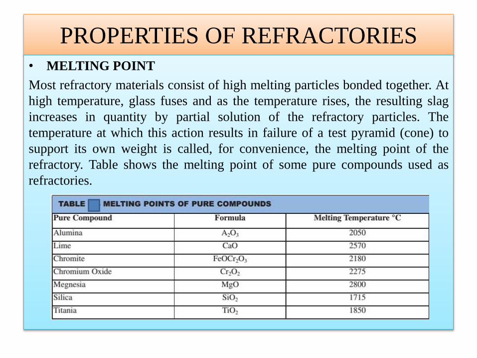
PROPERTIES OF REFRACTORIES• MELTING POINT
Most refractory materials consist of high melting particles bonded together. At
high temperature, glass fuses and as the temperature rises, the resulting slag
increases in quantity by partial solution of the refractory particles. The
temperature at which this action results in failure of a test pyramid (cone) to
support its own weight is called, for convenience, the melting point of the
refractory. Table shows the melting point of some pure compounds used as
refractories.

• BULK DENSITY:
Its defines the material present in a given volume. An increase in bulk density of a
given refractory increases its volume stability, its heat capacity, as well as resistance
to slag penetration.
• POROSITY:
The apparent porosity is a measure of the volume of the open pores, into which a
liquid can penetrate, as a percentage of the total volume. This is an important
property in cases where the refractory is in contact with molten charge and slags. A low
apparent porosity is desirable since it would prevent easy penetration of the refractory
size and continuity of pores will have important influences on refractory behaviour. A
large number of small pores is generally preferable to an equivalent number of large
pores.
• COLD CRUSHING STRENGTH:
the ability to withstand the rigors of transport, can be used as a useful indicator to
the adequacy of firing and abrasion resistance in consonance with other properties such
as bulk density and porosity.
PROPERTIES OF REFRACTORIES CONT.
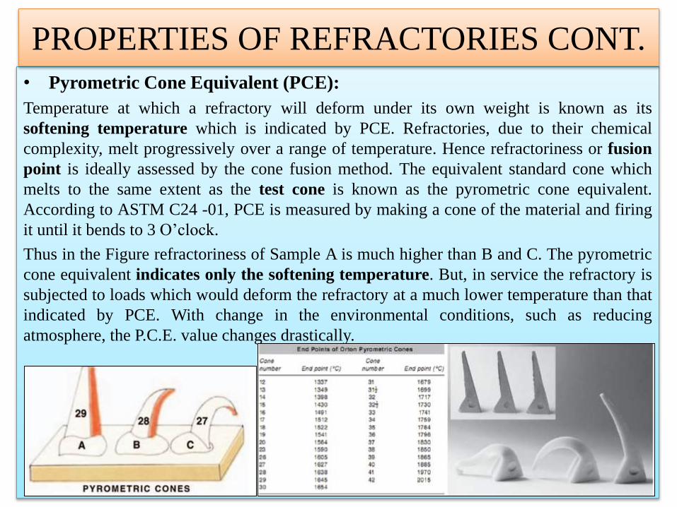
• Pyrometric Cone Equivalent (PCE):
Temperature at which a refractory will deform under its own weight is known as its
softening temperature which is indicated by PCE. Refractories, due to their chemical
complexity, melt progressively over a range of temperature. Hence refractoriness or fusion
point is ideally assessed by the cone fusion method. The equivalent standard cone which
melts to the same extent as the test cone is known as the pyrometric cone equivalent.
According to ASTM C24 -01, PCE is measured by making a cone of the material and firing
it until it bends to 3 O’clock.
Thus in the Figure refractoriness of Sample A is much higher than B and C. The pyrometric
cone equivalent indicates only the softening temperature. But, in service the refractory is
subjected to loads which would deform the refractory at a much lower temperature than that
indicated by PCE. With change in the environmental conditions, such as reducing
atmosphere, the P.C.E. value changes drastically.
PROPERTIES OF REFRACTORIES CONT.

• Refractoriness under load (RUL):
The refractoriness under load test (RUL test) gives an indication of the temperature at
which the bricks will collapse, in service conditions with similar load.
• Creep at high temperature:
Creep is a time dependent property which determines the deformation in a given time and
at a given temperature by a material under stress.
• Volume stability : Expansion and Shrinkage at high temperatures:
The contraction or expansion of the refractories can take place during service. Such
permanent changes in dimensions may be due to:
i) The changes in the allotropic forms which cause a change in specific gravity.
ii) A chemical reaction which produces a new material of altered specific
gravity.
iii) The formation of liquid phase.
iv) Sintering reactions.
v) It may also happen on account of fluxing with dust and stag or by the action
of alkalies on fireclay refractories, to form alkali-alumina silicates,
causing expansion and disruption. This is an example which is generally
observed in blast furnaces.
PROPERTIES OF REFRACTORIES CONT.

• Reversible Thermal Expansion:
Any material when heated, expands, and contracts on cooling. The reversible
thermal expansion is a reflection on the phase transformations that occur during
heating and cooling.
• Thermal Conductivity:
Thermal conductivity depends upon the chemical and mineralogical
compositions as well as the glassy phase contained in the refractory and the
application temperature. The conductivity usually changes with rise in
temperature. In cases where heat transfer is required though the brick work, for
example in recuperates, regenerators, muffles, etc. the refractory should have
high conductivity. Low thermal conductivity is desirable for conservation of heat
by providing adequate insulation.
PROPERTIES OF REFRACTORIES CONT.

REFRACTORY MATERIALS• Refractory materials must be chemically and physically stable at high
temperatures. Depending on the operating environment, they need to be resistant
to thermal shock, be chemically inert, and/or have specific ranges of thermal
conductivity and of the coefficient of thermal expansion.
• The oxides of aluminium (alumina), silicon (silica) and magnesium (magnesia)
are the most important materials used in the manufacturing of refractories. Another
oxide usually found in refractories is the oxide of calcium (lime). Fire clays are
also widely used in the manufacture of refractories.
• Refractories must be chosen according to the conditions they will face. Some
applications require special refractory materials. Zirconia is used when the
material must withstand extremely high temperatures. Silicon
carbide and carbon (graphite) are two other refractory materials used in some
very severe temperature conditions, but they cannot be used in contact
with oxygen, as they will oxidize and burn.
• Binary compounds such as tungsten carbide or boron nitride can be very
refractory. Hafnium carbide is the most refractory binary compound known, with
a melting point of 3890 °C.
• The ternary compound tantalum hafnium carbide has one of the highest melting
points of all known compounds (4215 °C).

CLASSIFICATION OF REFRACTORY MATERIALS
• Based on chemical composition
– Acidic refractories
– Neutral refractories
– Basic refractories
• Based on method of manufacture
– Dry press process
– Fused cast
– Hand molded
– Formed (normal, fired or
chemically bonded)
– Un-formed (monolithic-plastic,
ramming and gunning mass,
castables, mortars, dry vibrating
cements.)
– Un-formed dry refractories
• Based on fusion temperature
– Normal refractory: fusion
temperature of 1580 ~ 1780 °C
(e.g. Fire clay)
– High refractory: fusion
temperature of 1780 ~ 2000 °C
(e.g. Chromite)
– Super refractory: fusion
temperature of > 2000 °C (e.g.
Zirconia)

CLASSIFICATION OF REFRACTORY MATERIALS
CLASSIFICATION OF REFRACTORY
MATERIALS CONT.• Based on chemical composition
• Acidic refractories
Acidic refractories consist of mostly acidic materials like alumina (Al2O3)and silica (SiO2). They are generally not attacked or affected by acidic materials, buteasily affected by basic materials. They include substances such as silica, alumina, andfire clay brick refractories. Notable reagents that can attack both alumina and silica arehydrofluoric acid, phosphoric acid, and fluorinated gases (e.g. HF, F2). At hightemperatures, acidic refractories may also react with limes and basic oxides.
• Neutral refractories
These are used in areas where slags and atmosphere are either acidic or basic and arechemically stable to both acids and bases. The main raw materials belong to, but are notconfined to, the R2O3 group. Common examples of these materialsare alumina (Al2O3), chromia (Cr2O3) and carbon.
• Basic refractories
These are used in areas where slags and atmosphere are basic; they are stable toalkaline materials but could react with acids. The main raw materials belong to the ROgroup to which magnesia (MgO) is a very common example. Other examples includedolomite and chrome-magnesia. For the first half of the twentieth century, the steelmaking process used artificial periclase (roasted magnesite) as a lining material for thefurnace.
SELECTION OF REFRACTORIES
• The selection of refractories for any particular application is made with a view to achieve
the best performance of the equipment furnace, kiln or boiler and depends on their
properties. Further, the choice of a refractory material for a given application will be
determined by the type of furnace or heating unit and the prevailing conditions e.g. the
gaseous atmosphere, the presence of slags, the type of metal charge etc. It is, therefore,
clear that temperature is by no means the only criterion for selection of refractories.
• The furnace manufacturers or users have to consider the following points, before
selecting a refractory.
i) Area of application.
ii) Working temperatures.
iii) Extent of abrasion and impact.
iv) Structural load of the furnace.
v) Stress due to temperature gradient in the structures and temperature fluctuations.
vi) Chemical compatibility to the furnace environment.
vii) Heat transfer and fuel conservation
viii) Cost considerations.
HEAT LOSS AND ENERGY
CONSERVATION• Furnaces and kilns particularly depending on heat treatment or melting applications
operate at very high temperatures. Refractory bricks are used for internal lining of
furnace. When a furnace is heated up from cold, the first stage involves bringing the
brickwork up to temperature. The heat energy required for initial heat up depends to a
great extent upon the time cycle of the furnace. In a furnace with a weekly cycle when
the furnace is not used at weekends it will be considerable. With a daily cycle shutting
down over night it will still be considerable. Finally in furnaces operating on a heating
and cooling cycle in which the furnace is heated up with each charge of goods, the heat
consumed by the brickwork may assume quite surprising proportions in relation to the
heat usefully used.
• The heat stored in the body of the furnace depends on the weight of each component, its
specific heat and its average rise in temperature. There are two broad categories of
furnaces viz. continuous furnaces and intermittent batch type furnaces.
Whichever category of furnace is used, the heat losses result from
1) The loss through the furnace walls due to conduction, radiation and convection.
2) The loss due to the thermal mass of the furnace storing unnecessary heat

HEAT LOSS AND ENERGY
CONSERVATION CONT.• The striking benefits of the application of insulation to a furnace can be seen from the
following example:
• A refractory brick walled furnace with walls of a nominal 9” thickness and an internal
wall temperature of 2000°F will lose 145 BTUs per square feet. With a nominal 4” of
insulation the heat loss will be reduced to 32 BTUs per square feet and with nominal 8”
insulation to 18 BTUs per square feet.
• Heat losses can also be reduced to certain extent by increasing the thickness of the
refractory brick but this is not very effective as this method adds significant cost to the
furnace structure. It is much better to use insulation. But a word of caution: The insulation
of furnaces should not be adopted without careful consideration of the
• consequences and the changes in refractory temperatures that may result.
• Heat losses can also be reduced to certain extent by increasing the thickness of the
refractory brick but this is not very effective as this method adds significant cost to the
furnace structure. It is much better to use insulation. But a word of caution:
• The insulation of furnaces should not be adopted without careful consideration of the
• consequences and the changes in refractory temperatures that may result.

HEAT LOSS AND ENERGY
CONSERVATION CONT.• To sum up, the heat losses from walls depend on
• 1) Inside temperature
• 2) Outside air temperature
• 3) Outside air velocity
• 4) Configuration of walls
• 5) Emissivity of walls
• 6) Thickness of walls
• 7) Conductivity of walls
• The last two can be easily controlled by the furnace fabricator. The following conclusions can be drawn:
a) As the wall thickness increases, the heat losses reduce
b) As thickness of insulation is increased, heat losses reduce
c) The effect of insulation in reducing heat losses is more pronounced than the increase of wall thickness(roughly 1 cm of insulation brick is equivalent to 5 to 8 cm of refractory firebrick)
d) In intermittent furnaces, thin walls of insulating refractories are preferable to thick walls of a normalrefractory for intermittent operation since less heat is stored in them.
e) One approach to achieve less heat storage capacity would be to utilize insulating material itself to form theinner refractory lining. Robust refractories with fairly god strength and spelling resistance can be used fortemperature in the range of 1300° C. They are termed as hot face insulation.
f) Hot face insulating bricks are lighter than normal refractories, weighing only one third to one half as much.Therefore, heat storage in the hot face insulation is very much reduced.