insulators - ecemer elektrikecemerelektrik.com/wp-content/uploads/2019/06/ecemer-elektrik-kov… ·...
TRANSCRIPT
INSULATORS

INSULATORS
01/04 Post Insulators
08/10 Wall Bushings
05/06/07 Capacitive Divider Insulators
11 /12 Bolt Bushings
> INDOOR INSULATORS
GENERAL INFORMATION ON INSULATORS
Tightening torques
The table below applies when the length of the screw within the
threaded insert is at least 1,4 x screw diameter.
Screw Max.torque
[ Nm ]
Max.hole diameterin busbar
[ mm ]
M6 7 8
M8 12 10
M10 28 12
M12 45 15
M16 110 19
M20 150 24
M24 250 28
Um: Highest voltage for equipmentSpecifications and product designs are subject to change without prior notice in view of continuous improvements.
Rated insulation levels for post insulators
Um
[ kV ]
Dry powerfrequency withstand
voltage acc. to IEC 60273[ kV ]
Lightning impulsewithstand voltageacc. to IEC 60273
[ kV ]
3,6 10 40
7,2 28 60
12 38 75
17,5 50 95
24 50 125
36 70 170
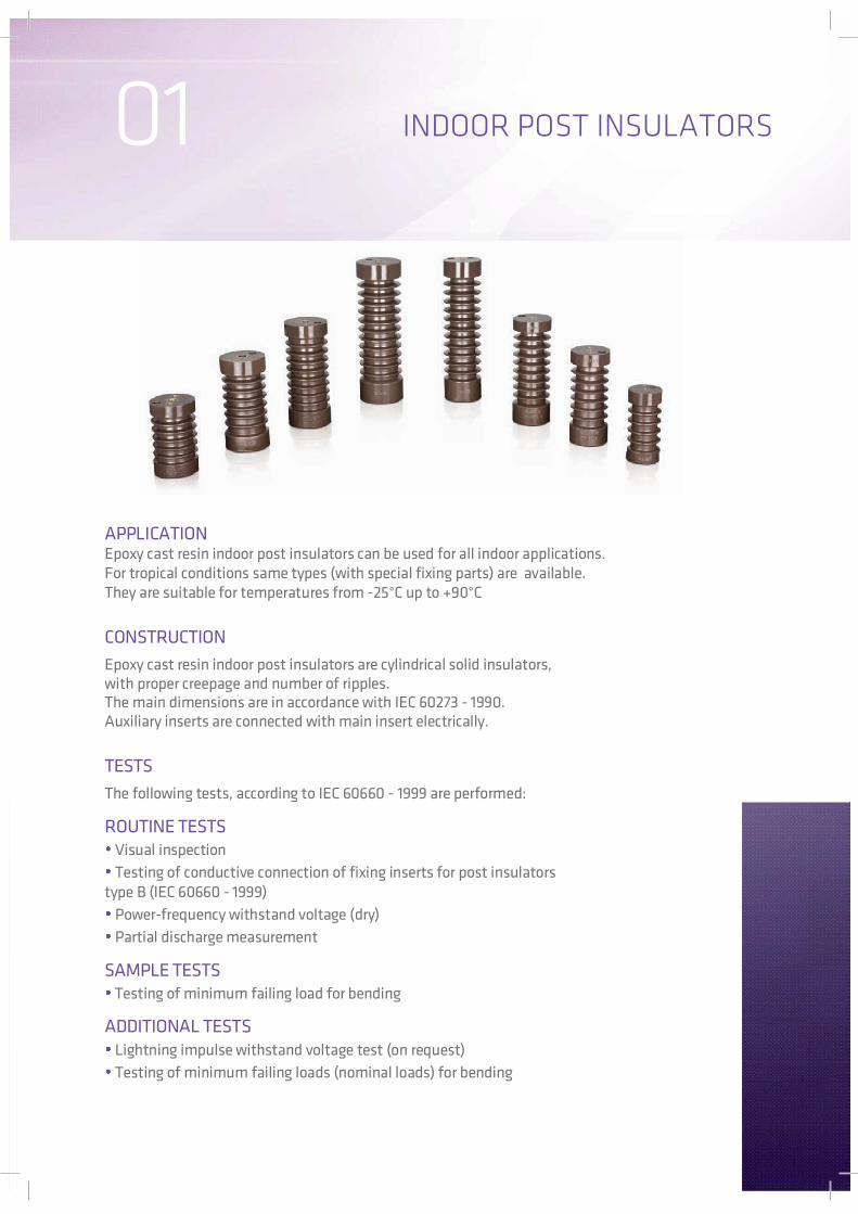
APPLICATIONEpoxy cast resin indoor post insulators can be used for all indoor applications.For tropical conditions same types (with special fixing parts) are available.They are suitable for temperatures from -25°C up to +90°C
CONSTRUCTION
Epoxy cast resin indoor post insulators are cylindrical solid insulators,with proper creepage and number of ripples.The main dimensions are in accordance with IEC 60273 - 1990.Auxiliary inserts are connected with main insert electrically.
TESTS
The following tests, according to IEC 60660 - 1999 are performed:
ROUTINE TESTS Visual inspection
Testing of conductive connection of fixing inserts for post insulatorstype B (IEC 60660 - 1999)
Power-frequency withstand voltage (dry)
Partial discharge measurement
SAMPLE TESTS Testing of minimum failing load for bending
ADDITIONAL TESTS Lightning impulse withstand voltage test (on request)
Testing of minimum failing loads (nominal loads) for bending
INDOOR POST INSULATORS01

e ±0.3
d2
d1
INDOOR POST INSULATORS
Part No Type Um[kV]
Weight
[kg]
PCS/Box
1000142 A10S-5007,2
130 2 500095
36 58 M16 M6 M10 26 2 0 10 38 0,39 16
1000145 B10S-1000 128 2 10000 46 71 M16 M10 M16 26 30 12 35 0,65 9
1000137 A10N-50012
165 4 5000130
36 56 M16 M6 M10 30 2 0 10 45 0,52 16
1000141 B10N-1000 184 5 10000 46 76 M20 M10 M16 35 30 12 47 1,00 9
1000165 A20S-50017,5
242 6 5000175
36 70 M16 M6 M10 30 2 0 10 42 1,00 16
1000169 B20S-1000 237 6 10000 46 83 M20 M10 M16 35 30 12 47 1,50 9
1000178 A20N-50024
303 6 5000210
36 70 M16 M6 M10 30 20 10 45 1,10 16
1000181 B20N-1000 307 8 10000 46 85 M20 M10 M16 35 30 12 47 1,90 9
1000197 A30N-50036
520 11 5000300
36 80 M16 M6 M10 35 20 10 47 2,10 9
1000201 B30N-1000 488 11 10000 46 95 M24 M10 M16 45 30 12 57 3,00 6
1000204 C30N-1600 453 11 16000 66 115 M30 M10 M16 45 30 12 68 4,80 6
Acc.to VDE 0674 -(1993), VDE 0111 - (1980]
Um: Highest voltage for equipment
Dimensions [mm]
Dimensions [mm]
h e d1 d2 d3 d4 t1 t2 t3 t4
h e d1 d2 d3 d4 t1 t2 t3 t4
[mm]
[mm]
[N]
[N]
Part No Type Um[kV]
Weight
[kg]
PCS/Box
7,2 951000218 J06-60 130 2 6000 36 58 M16 M6 M12 26 18 9 38 0,38 32
1000220 J010-60 128 2 10000 46 71 M16 M10 M16 26 30 12 35 0,65 9
12 1301000139 J06-75 165 4 6000 36 56 M16 M6 M12 30 18 9 45 0,49 16
1000150 JO10-75 184 5 10000 46 76 M20 M10 M16 35 30 12 47 1,00 9
17,5 1751000167 J06-95 242 6 6000 36 70 M16 M6 M12 30 18 9 42 1,00 16
1000170 J010-95 237 6 10000 46 83 M20 M10 M16 35 30 12 47 1,40 9
24 2101000179 J06-125 303 6 6000 36 70 M16 M6 M12 30 18 9 45 1,10 16
1000185 JO10-125 307 8 10000 46 85 M20 M10 M16 35 30 12 47 1,82 9
36 300
1000199 JO6-170 520 11 6000 36 80 M16 M6 M12 35 18 9 47 2,10 9
1000210 J010-170 488 11 10000 46 95 M24 M10 M16 46 30 12 58 3,00 6
1000203 J016-170 453 11 16000 66 115 M24 M10 M16 46 30 12 69 4,80 6
Acc.to lEC 60273 - (1990), lEC 60660 - (1999)
Um: Highest voltage for equipment

03Technical Data
H øF øD h1 (mm) ~kV ~kV Nm Nm
60 M10 55 14 93 2 3 15 40 75 23.90 50
M10 18 40 75 63.30
M12 20 70 75 64.10
M16 20 95 100 64.80
82553123
Min.Creepage
Part No.
1N-500
83801N-1000
Max. Tightening
TorqueTorque
Strength
Weight kg/100 pcs.
Box Qty.
Service Voltage
Test Voltage
Dimensions (mm)Ripples
LV INSULATORS
TYPE 1N
Color: Brown

Technical Data
04LV INSULATORS
TYPE SK
Color: Brown
H øF SW øD h1 ~kV ~kV kN kN Nm Nm
M8 8 3 6 20 40 5.30
M10 9 3 6 30 40 5.10
M8 10 5 8 20 40 10.70
M10 12 6 10 40 75 11.50
M10 14 7 14 40 75 19.00
M12 15 9 12 70 125 20.10
M10 14 6 18 40 75 38.00
M12 16 9.5 25 70 105 38.50
3540 2
30 30 26 1.5 10 80
60 60 43 3 15 24
50 50 42 2 15 50
15
Cantilever Strength
Service Voltage
Tensile Strength
Max. Tightening
TorqueTorque
StrengthTest
Voltage
40
Weight kg/100 pcs.
Box Qty.
Dimensions (mm)
75
SK-303008
SK-303010
SK-404008
SK-404010
SK-505010
SK-505012
SK-606010
SK-606012
Part No.
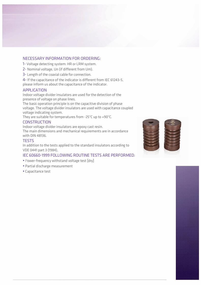
NECESSARY INFORMATION FOR ORDERING:1- Voltage detecting system: HR or LRM system.
2- Nominal voltage, Un (if different from Um).
3- Length of the coaxial cable for connection.
4- lf the capacitance of the indicator is different from IEC 61243-5,please inform us about the capacitance of the indicator.
APPLICATIONIndoor voltage divider insulators are used for the detection of thepresence of voltage on phase lines.The basic operation principle is on the capacitive division of phasevoltage. The voltage divider insulators are used with capacitance coupledvoltage indicating system.They are suitable for temperatures from -25°C up to +90°C.
CONSTRUCTIONIndoor voltage divider insulators are epoxy cast resin.The main dimensions and mechanical requirements are in accordancewith DIN 48136.
TESTSIn addition to the tests applied to the standard insulators according to
VDE 0441 part 3 (1984),
IEC 60660-1999 FOLLOWING ROUTINE TESTS ARE PERFORMED: Power-frequency withstand voltage test [dry]
Partial discharge measurement
Capacitance test
Capacitance-coupled voltageindication systemThe voltage indication system consists
essentially of a capacitive voltage
divider between a conductor L and
earth. Moreover, the system includes an
indicator for the detection of voltage
and a surge arrester for protection
purposes.
Shock hazard protectionVoltage indication system does not
present any risk during normal or
disturbed operation. During normal
operation, the voltage divider
capacitance CI limits the currents to
less than 100µ±A.
FunctionVoltage division occurs due to thecapacitive values of C1 and C2.According to IEC 61243-5 the indicationshould start in between 10% of the readvoltage of the system. For that reason,the capacitance values are adjusted inaccordance within this range so thatthe indication starts.Up to 10% of the rated voltage, thereshall be no indication. Under anycircumstance above 45% of the ratedvoltage the indication shall be “ON”.The presence of voltage is indicatedseparately and independently for eachphase conductor. The system operateswithout a battery or auxiliary supply.The energy required for the system isbeing drawn from the high voltagesystem (CAPDIS system may requireauxiliary power for some additionalfunctions depending on the application).
Capacitive voltage indicating system for medium voltage
CAPACITIVE DIVIDER INSULATORS
L
C1
C2Surgearrester
Voltageindicator
Coaxial cablewith surge arrester
Interface point
Insulationcable
Plug socket Plug
05

Part No Type Um(kV)
Capacitance(LCR meter)
Weight
[kg]
PCS/Box
1000514 DKA-10N7.2
184 521 ±20%
5000130
30 36 76 M16 M6 M10 25 20 10 37 0,9 9
1000515 DKB-10N 184 5 10000 30 46 76 M20 M10 M16 24 20 12 36 1,0 9
1000514 DKA-10N12
184 521 ±20%
5000130
30 36 76 M16 M6 M10 25 20 10 37 0,9 9
1000515 DKB-10N 184 5 10000 30 46 76 M20 M10 M16 24 20 12 36 1,1 9
1000516 DKA-20S17.5
237 621 ±20%
5000175
30 36 83 M16 M6 M10 35 20 10 47 1,3 9
1000517 DKB-20S 237 6 10000 30 46 83 M20 M10 M16 35 30 12 47 1,4 9
1000518 DKA-20N24
300 816 ±20%
5000210
30 36 85 M16 M6 M10 35 20 10 47 1,8 9
1000519 DKB-20N 300 8 10000 30 46 85 M20 M10 M16 35 30 12 47 1,9 9
1000520 DKA-30N
36
438 117,5 ±20%
5000
300
34 36 103 M16 M6 M10 35 20 10 47 3,8 6
1000521 DKB-30N 438 11 10000 34 46 103 M24 M10 M16 46 30 12 58 6
Um: Highest voltage for equipment
ATTENTION!
The insulators should be used for indication purposes and should not be exposed to excessive dynamic loads.
Dimensions [mm]
[N]
CAPACITIVE DIVIDER INSULATORS(FOR INDICATION AND STATIC LOADS)
F
d2
t2 d3
d4
h ±1
t4 ±2
t3 t1
[mm] h E e d1 d2 d3 d4 t1 t2 t3 t4
1032399 DKB-30N 438 11 16 ±20% 10000 34 46 103 M24 M10 M16 46 30 12 58 6
3,7
3,7
Part No Type Um(kV)
Capacitance(LCR meter)
Weight
[kg]
PCS/
Box
1000508 KA-20S17,5
237 6 5000 30 36 83 M16 M6 M10 33 20 10 45 1,3 9
1000509 KB-20S 237 6 10000 30 46 83 M20 M10 M16 35 20 20 47 1,4 9
1000510 KA-20N24
300 5000 30 36 M16 M6 M10 33 20 10 45 1,8 9
1000511 KB-20N 300 8 10000 30 46 85 M20 M10 M16 38 20 12 50 1,9 9
1000443 EK30N-400
36
520 11 4000 30 36 80 M12 M6 M10 23 20 9 33 2,15 9
1000512 KA-30N 488 11 5000 34 36 95 M16 M6 M10 33 20 10 45 3,00 6
1000513 DKB-30N/E 488 11 10000 34 46 95 M24 M10 M16 48 30 12 60 3,18 6
Dimensions [mm]
[ pF ] [N]
Um: Highest voltage for equipment
ATTENTION!
The insulators should be used only for indication purposes and should not be exposed to dynamic loads .
[mm] h E e d1 d2 d3 d4 t1 t2 t3 t4
CAPACITIVE DIVIDER INSULATORS(FOR INDICATION AND STATIC LOADS)
d2
t2
h ±1
t1 d3
d4
t4 ±2
t3
F
07
16 ±20%
175
210
300
858
50 ±20%
100 ±20%

Um: Highest voltage for equipment
WALL BUSHING TYPE GKB
GKB-12
GKB-36
Ø194,5
Ø228
Ø170
120
Ø9
Ø51
Ø80
Ø9Ø9
84
24
Part no:1000120
Part no:1000347
F
Ø188
Ø175
Ø158 Ø81
Ø9
Ø9 86192222260
Part No Type RatedVoltage
Um [kV]
InsulationVoltage
[ kV]
Lightningimpulsevoltage
[ kV ]
Min.Bending
[N]
Busbar
[mm]
Weight
[kg]
Pcs/Box
1000120 GKB-36 36 70 170 3750 80X24 12.0 1
1000347 GKB-36 36 70 170 3750 Ø50 12.0 1
1000319 GKB-12 12 38 75 4000 Ø80 3.45 1
Dimensions and shape of the hole in the
center (will be used for the assembly of
customer requirements.
Um: Highest voltage for equipment
for 1 busbar
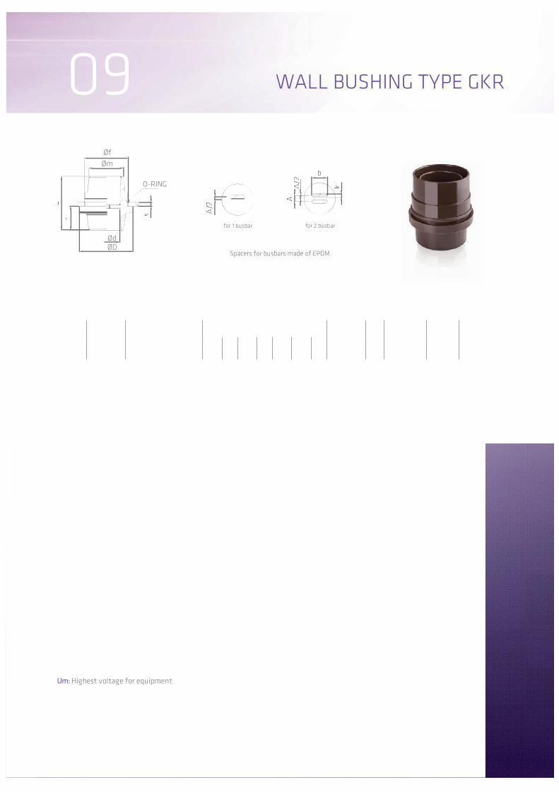
09 WALL BUSHING TYPE GKR
Øf
O-RING
b
Spacers for busbars made of EPDM
for 2 busbar
ØdØD
Øm
Part No TypeRated voltage
[kV]
Bar
dimensions
[ mm ] A
b x k
[ mm ]
Weight
[ kg ]
Pcs/Box
L c ØD Ød Øm Øf s
1000125GKR 6/60 12 kV insulating plate;
7,2 kV in sheet of metal120 55 120 62 77 96 10 1x(50x10)
-1x(50,5x10,5) 1,00 10
1000110
1000111GKR 12/75 12 kV insulating plate;
7,2 kV in sheet of metal120 53 130 75 98 115 6 1x(60x10)
2x(60x10)20
1x(65x14)
2x(65x14) 1,24 10
1000117
1000118
GKR 24/7524-36 kV insulating plate;
12 kV in sheet of metal150 65 140 75 114 125 6 1x(60x10)
2x(60x10)20
1x(65x14)
2x(65x14)1,58 10
Dimensions [ mm ]
a aMounting oninsulating plate
Metal frame
Urn
[kV]
Lightning
Impulse
voltage
[kV]
Min.distance
“a”
at impulse
voltage
[ mm ]
Dry power frequency
withstand voltage
at distance “a”
[kV]
12 75 60 42
24 125 178 75
36 170 260 95
10
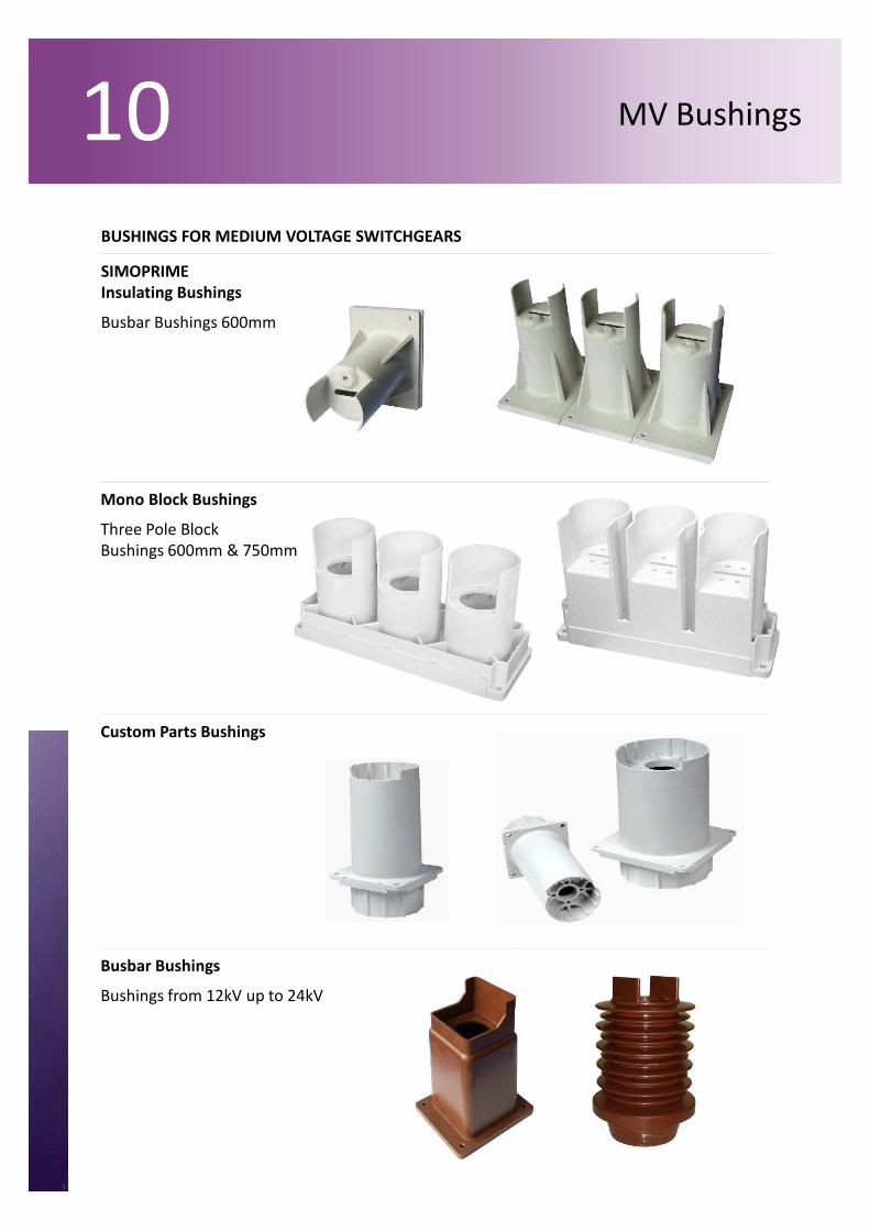
Mono Block Bushings
Three Pole Block
Bushings 600mm & 750mm
SIMOPRIME
Insulating Bushings
Busbar Bushings 600mm
Custom Parts Bushings
Busbar Bushings
Bushings from 12kV up to 24kV
MV Bushings
BUSHINGS FOR MEDIUM VOLTAGE SWITCHGEARS

OUTDOOR TO INDOORBOLT BUSHING TYPE HDGB
Ød1
HDGB-10,M10HDGB-15,M12
HDGB-30,M12max.k
L4 L2 L3 L5
L1
L
PN PN
b
c
1
Test load shall be applied to each end of the bushing separately Assembly should be done according to the assembly instructions
that are given with the product.
Part No Type Um
[ kV ]
RatedCurrent
[ A ]
Min.Bending
[ N ]
Weight
[ kg ]Pcs/Box
1000027
HDGB-10 12
100-250
3750
450
345 180 165
55 50
135 100 80 21
M12
11 75 135 50
3,06
1
1000028 400 470 65 60 M16 3,50
1000029 630 490 75 70 M20 4,32
1000030 800 530 95 90 M24X2 4,58
1000031 1000 560 110 105 M30X1,5 6,89
1000032 1250 580 120 115 M32X1,5 8,07
1000033
HDGB-15 17,5
100-250
3750
560
455 245 210
55 50
160 120 90 27
M12
13 90 155 55
4,16
1
1000062 400 580 65 60 M16 4,70
1000064 630 600 75 70 M20 5,58
1000066 800 640 95 90 M24X2 6,00
1000068 1000 670 110 105 M30X1,5 8,56
1000070 1250 690 120 115 M32X1,5 9,80
1000099
HDGB-30 36
100-250
3750
845
740 348 392
55 50
210 140 140 33
M12
17 110 175 60
9,40
1
1000101 400 865 65 60 M16 10,13
1000103 630 885 75 70 M20 11,35
1000104 800 925 95 90 M24X2 12,05
1000105 1000 955 110 105 M30X1,5 15,22
1000107 1250 975 120 115 M32X1,5 16,74
Dimensions [ mm ]
Um: Highest voltage for equipment
L L1 L2 L3 L4 L5 a a1 b c d Ød1 Ød2 Ød3 k

Test load shall be applied to each end of the bushing separately. Assembly should be done according to the assembly instructions
that are given with the product.
Part No Type Um
[ kV ]
RatedCurrent
[ A ]
Min.Bending
[ N ]
Weight
[ kg ]Pcs/Box
1000016
DDGB-10/4M 12
100-250
3750
385
287 131
50
156 135 100 21
M12
11 80 50
2,18
1
1000018 400 405 60 M16 2,62
1000020 630 425 70 M20 3,18
1000022 800 465 90 M24X2 3,97
1000024 1000 495 105 M30X1,5 5,31
1000026 1250 515 115 M32X1,5 5,98
1000048
DDGB-15/4M 17,5
100-250
3750
535
439 217
50
222 140 100 20
M12
13 80 55
3,43
1
1000050 400 555 60 M16 3,99
1000052 630 575 70 M20 4,71
1000054 800 615 90 M24X2 5,68
1000056 1000 645 105 M30X1,5 7,36
1000058 1250 665 115 M32X1,5 8,16
1000086
DDGB-30/4M 36
100-250
3750
825
725 343.5
50
381,5 150 100 28
M12
17 110 60
7,10
1
1000087 400 845 60 M16 8,00
1000088 630 865 70 M20 9,20
1000089 800 905 90 M24X2 1,00
1000090 1000 935 105 M30X1,5 13,60
1000091 1250 955 115 M32X1,5 14,85
L L1 L2 L3 L4 a a1 c d Ød1 Ød2 k
Dimensions [ mm ]
12
Um: Highest voltage for equipment
INDOOR TO INDOORBOLT BUSHING TYPE DDGB
