integra user manual revision 2.1 ii - laser power meter ... · integra user manual revision 2.1 ii...
TRANSCRIPT

INTEGRA User Manual Revision 2.1 ii
WARRANTY
First Year Warranty All Gentec-EO devices carry a one-year warranty (from date of shipment) against material and/or workmanship defects, when used under normal operating conditions. The warranty does not cover damages related to battery leakage or misuse. Gentec-EO Inc. will repair or replace, at Gentec-EO Inc.’s option, any device that proves to be defective during the warranty period, except in the case of product misuse. Any attempt by an unauthorized person to alter or repair the product voids the warranty. The manufacturer is not liable for consequential damages of any kind. In case of malfunction, contact your local Gentec-EO distributor or nearest Gentec-EO Inc. office to obtain a return authorization number. The material should be returned to: Contacting Gentec Electro-Optics Inc.
Gentec Electro-Optics, Inc. 445, St-Jean-Baptiste, Suite 160
Québec, QC Canada G2E 5N7
Tel: (418) 651-8003 Fax: (418) 651-1174
Email: [email protected]
Website: www.gentec-eo.com
CLAIMS To obtain warranty service, contact your nearest Gentec-EO agent or send the product, with a description of the problem, and prepaid transportation and insurance, to the nearest Gentec-EO agent. Gentec-EO Inc. assumes no risk for damage during transit. Gentec-EO Inc. will, at its option, repair or replace the defective product free of charge or refund your purchase price. However, if Gentec-EO Inc. determines that the failure is caused by misuse, alterations, accident or abnormal conditions of operation or handling, it would therefore not be covered by the warranty.

INTEGRA User Manual Revision 2.1 iii
SAFETY INFORMATION Do not use a Gentec-EO device, if the monitor or the detector looks damaged, or if you suspect that the device is not operating properly. Appropriate installation must be done for water-cooled and fan-cooled detectors. Refer to the specific instructions for more information. Wait a few minutes before handling the detectors after power is applied. Surfaces of the detectors get very hot and there is a risk of injury if they are not allowed to cool down. Note: This equipment has been tested and found to comply with the limits for a Class A digital device,
pursuant to part 15 of the FCC Rules. These limits are designed to provide reasonable protection against harmful interference in a residential installation. This equipment generates, uses, and can radiate radio frequency energy. If not installed and used in accordance with the instructions, it may cause harmful interference to radio communications. However, there is no guarantee that interference will not occur in a particular installation. If this equipment does cause harmful interference to radio or television reception, which can be determined by turning the equipment off and on, try to correct the interference by taking one or more of the following steps:
• Reorient or relocate the receiving antenna. • Increase the distance between the equipment and receiver. • Connect the equipment to an outlet that is on a different circuit than the receiver. • Consult the dealer or an experienced radio/TV technician for help.
Caution: Changes or modifications not expressly approved in writing by Gentec-EO Inc. may void the
user’s authority to operate this equipment.

INTEGRA User Manual Revision 2.1 iv
TABLE OF CONTENTS
1. INTEGRA ......................................................................................................................... 1
1.1. Introduction .................................................................................................................................................1 1.2. Specifications .............................................................................................................................................1 1.1. Outline Drawing ..........................................................................................................................................2
INTEGRA Original Series ..................................................................................................................................2 INTEGRA USB (New Series) ............................................................................................................................2 INTEGRA RS-232 (New Series) .......................................................................................................................3 DB-9 Pinout .......................................................................................................................................................3
2. Quick Start Procedure ................................................................................................... 4
3. User Interface ................................................................................................................. 5
4. USB and RS-232 Serial Communication ...................................................................... 5
4.1. Description .................................................................................................................................................5 4.2. Setting up Communication to the INTEGRA ..............................................................................................5
4.2.1. Verify the COM Port ............................................................................................................................5 4.2.2. Connect the INTEGRA ........................................................................................................................5 4.2.3. To Echo Commands ...........................................................................................................................6 4.2.4. Test the Connection ............................................................................................................................6 4.2.5. To Add a Character Delay ..................................................................................................................6 4.2.6. HyperTerminal Settings Shortcut ........................................................................................................6
4.3. Serial Command Format ............................................................................................................................7 4.3.1. Serial Protocol Rules: .........................................................................................................................7 4.3.2. Text Mode Rules: ................................................................................................................................7
4.4. Binary Mode output Format ........................................................................................................................7 4.4.1. Description ..........................................................................................................................................7 4.4.2. Codification .........................................................................................................................................7
4.5. List of Serial Commands for the INTEGRA (Summary) .............................................................................9 4.6. List of Serial Commands for the INTEGRA (Complete) .......................................................................... 10
4.6.1. Display ............................................................................................................................................. 10 01 - Set Scale ............................................................................................................................................................... 10 02 - Set Scale Up ......................................................................................................................................................... 11 03 - Set Scale Down ..................................................................................................................................................... 11 04 - Get Current Scale Index ........................................................................................................................................ 11 05 - Set Autoscale ........................................................................................................................................................ 11 06 - Get Autoscale ........................................................................................................................................................ 11 07 - Display Valid Scale ............................................................................................................................................... 12 08 - Set Trigger Level ................................................................................................................................................... 12 09 - Get Trigger Level .................................................................................................................................................. 13 10 – Get Measure Mode Display .................................................................................................................................. 13
4.6.2. Data Acquisition ............................................................................................................................... 13 11 - Query Current Value ............................................................................................................................................. 13 12 - Send Continuous Transmission of Data ................................................................................................................ 14 13 - Send Continuous Value with Frequency ............................................................................................................... 15 14 - Sent Current Value with Frequency ...................................................................................................................... 15 15 - Stop the CAU Command ....................................................................................................................................... 15 16 - Get Laser Frequency ............................................................................................................................................ 16 17 - Set Binary Joulemeter Mode ................................................................................................................................. 16 18 - Get Binary Joulemeter Mode ................................................................................................................................. 16
4.6.3. Setup ................................................................................................................................................ 16 19 - Set Personal Wavelength Correction .................................................................................................................... 16 20 - Get Wavelength .................................................................................................................................................... 17
4.6.4. Control .............................................................................................................................................. 17 21 - Set Anticipation ..................................................................................................................................................... 17 22 - Get Anticipation Status .......................................................................................................................................... 17

INTEGRA User Manual Revision 2.1 v
23 - Noise Suppression ................................................................................................................................................ 18 24 - Set Zero Offset ...................................................................................................................................................... 18 25 - Clear Zero Offset ................................................................................................................................................... 19 26 - Get Zero Offset ..................................................................................................................................................... 19 27 - Set Diode Zero Offset ........................................................................................................................................... 19 28 - Set User Multiplier ................................................................................................................................................. 19 29 - Get User Multiplier ................................................................................................................................................ 20 30 - Set User Offset ...................................................................................................................................................... 20 31 - Get User Offset ..................................................................................................................................................... 20 32 - Set Single Shot Energy Mode ............................................................................................................................... 21 33 - Set Attenuator ....................................................................................................................................................... 21 34 - Get Attenuator ....................................................................................................................................................... 21
4.6.5. Instrument and Detector Information ............................................................................................... 22 35 - Change baud rate for RS-232 ............................................................................................................................... 22 36 - Query Version ....................................................................................................................................................... 22 37 - Query Status ......................................................................................................................................................... 22 38 - Query Extended Status ......................................................................................................................................... 24
4.7. Error Messages ....................................................................................................................................... 25
5. USB Driver Installation ................................................................................................ 26
6. Maintenance ................................................................................................................. 27
6.1. Free Software Upgrade ........................................................................................................................... 27 6.2. Troubleshooting....................................................................................................................................... 27
7. Declaration of Conformity ........................................................................................... 28
Appendix A: WEEE Directive ............................................................................................... 30

INTEGRA User Manual Revision 2.1 1
1. INTEGRA
1.1. INTRODUCTION The INTEGRA is a series of All-in-One detectors that combine a detector and a meter in one convenient product. The small but powerful meter of the INTEGRA Series presents a direct USB or RS-232 connection so you can plug it into your PC. Simply use the PC-Gentec-EO software supplied with your product and be ready to make power or energy measurements within seconds! Each detector of the INTEGRA Series offers the same incredible performance as the usual detector and meter combination, from pW to kW and from fJ to J. And the good news is that all our most popular products are available with the INTEGRA option.
1.2. SPECIFICATIONS The following specifications are based on a one-year calibration cycle, an operating temperature of 18 to 28ºC (64 to 82ºF) and a relative humidity not exceeding 80%. INTEGRA must be stored in an environment between 10
oC to 45
oC (50 to 113
oF) and a relative humidity not exceeding 90%. Photodiodes are sensitive to
temperature, especially at longer wavelength. It is the best to keep the temperature in the range of 25 o
C (77 o
F) close to the calibration temperature.
Power Meter Specifications
Power Range 4 pW to 30 kW Power Scales: Photo Detectors Thermal Detectors
21 scales: 300 pW to 3 W
16 scales: 300 µW to 30 kW
Pyroelectric in Power Mode (UM-B) 8 scales : 100 µW, to 300 mW
Accuracy1 ±2.5%
1 5 µV best scale
1
Energy Meter Specifications
Energy Range 2 fJ to 30 kJ Energy Scales: Photo Detectors Pyroelectric Detector
22 scales: 300 fJ to 30 mJ 15 scales: 3 mJ to 30 kJ
Accuracy 2 3.0%
250 µV < 5.2 kHz best scale.
Trigger Level: Default Software
2 %
0.1% to 99.9%, 0.1% resolution
Data Transfer Rate No missing points throughput serial frequency(power and energy):
5200 Hz, 200 Hz via RS-232@115200bps
Frequency Measurement Accurate frequency measurement up to 5.2 kHz
0-5200 Hz: ±1%
Voltage range for RS-232 supply 4-30 Vdc @ 60 mA
Voltage range for special option External trigger
2.5- 18 volts, max 20 volts.
Software Specifications
Please refer to the PC-Gentec-EO manual (202322)
1 Including linearity, detector accuracy and is detector dependent.
2 Excludes non-linearity.
INTEGRA User Manual Revision 2.1 2
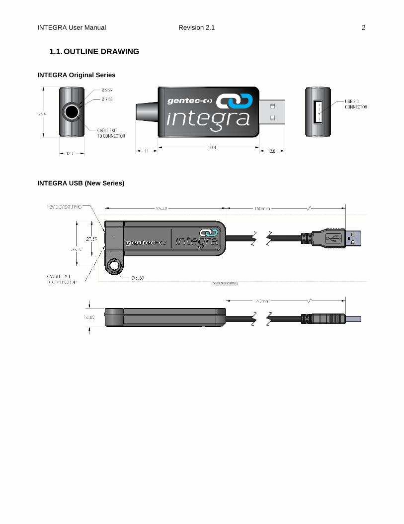
1.1. OUTLINE DRAWING INTEGRA Original Series
INTEGRA USB (New Series)
INTEGRA User Manual Revision 2.1 3
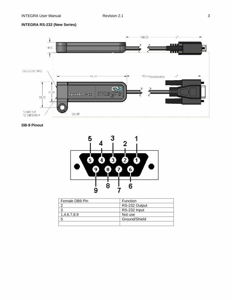
INTEGRA RS-232 (New Series)
DB-9 Pinout
Female DB9 Pin Function
2 RS-232 Output
3 RS-232 Input
1,4,6,7,8,9 Not use
5 Ground/Shield
INTEGRA User Manual Revision 2.1 4
2. QUICK START PROCEDURE
1. Install the PC-Gentec-EO software on your PC.
2. Install the power or energy detector head on its optical stand.
3. Connect the INTEGRA device to the PC with the appropriate USB cable.
4. Start the PC-Gentec-EO software.
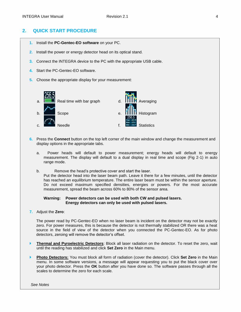
5. Choose the appropriate display for your measurement:
a. Real time with bar graph
b. Scope
c. Needle
d. Averaging
e. Histogram
f. Statistics
6. Press the Connect button on the top left corner of the main window and change the measurement and display options in the appropriate tabs.
a. Power heads will default to power measurement; energy heads will default to energy measurement. The display will default to a dual display in real time and scope (Fig 2-1) in auto range mode.
b. Remove the head’s protective cover and start the laser.
Put the detector head into the laser beam path. Leave it there for a few minutes, until the detector has reached an equilibrium temperature. The entire laser beam must be within the sensor aperture. Do not exceed maximum specified densities, energies or powers. For the most accurate measurement, spread the beam across 60% to 80% of the sensor area. Warning: Power detectors can be used with both CW and pulsed lasers.
Energy detectors can only be used with pulsed lasers. 7. Adjust the Zero:
The power read by PC-Gentec-EO when no laser beam is incident on the detector may not be exactly zero. For power measures, this is because the detector is not thermally stabilized OR there was a heat source in the field of view of the detector when you connected the PC-Gentec-EO. As for photo detectors, zeroing will remove the detector’s offset.
Thermal and Pyroelectric Detectors: Block all laser radiation on the detector. To reset the zero, wait until the reading has stabilized and click Set Zero in the Main menu.
Photo Detectors: You must block all form of radiation (cover the detector). Click Set Zero in the Main menu. In some software versions, a message will appear requesting you to put the black cover over your photo detector. Press the OK button after you have done so. The software passes through all the scales to determine the zero for each scale.
See Notes

INTEGRA User Manual Revision 2.1 5
Notes:
a. Refer to specific power detector documentation for complete installation and operating instructions. b. Power detectors are thermal sensors and are thus sensitive to temperature variations. c. For high-precision measurements, it is recommended to:
i. Allow the power detector to thermally stabilize before zeroing the software. ii. Touch only the stand when handling the power detector. Do not touch the detector itself. This is
especially true for highly sensitive detectors. iii. Do not adjust the zero for energy detectors, such as the QE series. iv. Avoid forced airflow or drafts around the detector.
3. USER INTERFACE
Please refer to the PC-Gentec-EO manual for more information concerning the user interface. The manual can be downloaded on our website at https://gentec-eo.com/downloads/specsheets-manuals.
4. USB AND RS-232 SERIAL COMMUNICATION
4.1. DESCRIPTION The INTEGRA has two Communication Modes: the Binary Mode for fast data acquisition and the ASCII mode. Both modes will require text input commands which must follow rules stated in section 4.3. The output can be in binary mode or in ASCII mode. Section 4.6 describes all the commands in ASCII output mode, but keep in mind, it is also valid for Binary Mode as described in section 4.4. The USB class used by INTEGRA is a CDC, or Communications Device Class. This means it shows up in the host PC as a COM port, but it is not a COM port, rather a true full speed USB port. You can talk to it like as if it were an RS232 port, but very fast when it comes to speed. Follow the Windows Prompts to install the USB drivers. The USB drivers are fully tested and digitally signed by Microsoft. Open the appropriate port in your software with standard COM port tools. None of the port settings matter since they are not used, so leave them at whatever default they are in. It’s a real USB connection. Use the standard COM port writes and reads to control the INTEGRA.
4.2. SETTING UP COMMUNICATION TO THE INTEGRA
4.2.1. Verify the COM Port To verify the USB installation and find the COM port number, click: Start → Settings → Control Panel → System → Device Manager Scroll down to Ports (COM & LPT) and double click that line. One of the options should be
USB-to-Serial Port (COM#)
Note the COM port number, you will need it for the next step.
4.2.2. Connect the INTEGRA You may use any serial communications software that you are familiar with. Our instructions are for
HyperTerminal because it is widely available on PCs with Windows.
INTEGRA User Manual Revision 2.1 6
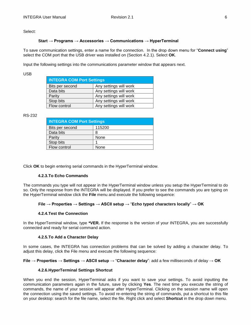
Select: Start → Programs → Accessories → Communications → HyperTerminal To save communication settings, enter a name for the connection. In the drop down menu for “Connect using” select the COM port that the USB driver was installed on (Section 4.2.1). Select OK. Input the following settings into the communications parameter window that appears next. USB
INTEGRA COM Port Settings
Bits per second Any settings will work
Data bits Any settings will work
Parity Any settings will work
Stop bits Any settings will work
Flow control Any settings will work
RS-232
INTEGRA COM Port Settings
Bits per second 115200
Data bits 8
Parity None
Stop bits 1
Flow control None
Click OK to begin entering serial commands in the HyperTerminal window.
4.2.3. To Echo Commands The commands you type will not appear in the HyperTerminal window unless you setup the HyperTerminal to do so. Only the response from the INTEGRA will be displayed. If you prefer to see the commands you are typing on the HyperTerminal window click the File menu and execute the following sequence:
File → Properties → Settings → ASCII setup → “Echo typed characters locally” → OK
4.2.4. Test the Connection In the HyperTerminal window, type *VER. If the response is the version of your INTEGRA, you are successfully connected and ready for serial command action.
4.2.5. To Add a Character Delay In some cases, the INTEGRA has connection problems that can be solved by adding a character delay. To adjust this delay, click the File menu and execute the following sequence: File → Properties → Settings → ASCII setup → “Character delay”: add a few milliseconds of delay → OK
4.2.6. HyperTerminal Settings Shortcut When you end the session, HyperTerminal asks if you want to save your settings. To avoid inputting the communication parameters again in the future, save by clicking Yes. The next time you execute the string of commands, the name of your session will appear after HyperTerminal. Clicking on the session name will open the connection using the saved settings. To avoid re-entering the string of commands, put a shortcut to this file on your desktop: search for the file name, select the file. Right click and select Shortcut in the drop down menu.

INTEGRA User Manual Revision 2.1 7
4.3. SERIAL COMMAND FORMAT
4.3.1. Serial Protocol Rules: Commands are sent as text strings. The response will either be data or an empty string.
4.3.2. Text Mode Rules: All text commands must begin with a trig character (*). You do not need to end with a line-feed and/or a carriage-return. Parameters must NOT be separated by spaces. Characters do not have to be capitals, mixed upper and lower cases is ok. Replies to all text mode commands are also in text mode, and end with a carriage-return and a line-feed. In case of an error, the reply string is one of the following : “Command Error. Command not recognized.” or
“Command Error. Command must start with '*'”
Because all Text Mode replies end with a carriage return <CR> or line-feed <LF> (or both), a text reply contains tabulations when many elements need to be separated in the string. This is useful when exporting data to a spreadsheet.
4.4. BINARY MODE OUTPUT FORMAT
4.4.1. Description The resolution of both is 12-bit in Joulemeter mode. A 14-bit value is sent for compatibility with other meters, but the two LSB’s are not significant. Only the Joulemeters support the binary mode. Thermopiles in energy mode, thermal heads in standard mode and photo detectors are coded in ASCII. The value in binary mode is coded in two bytes.
4.4.2. Codification When retrieving a measurement with either *cau or *cvu command the output is decoded as follow: Byte 1 OXXX XXXX Byte 2 OXXX XXXX Where O is the byte Order bit, and X is the binary data. If O is 0, the byte is the MSB. If O is 1, the byte is the LSB See the table below for examples on how to use binary commands.

INTEGRA User Manual Revision 2.1 8
How to Use Binary Commands
Example 1: Out of Scale Condition when Using *CEU or *CTU
If the value of these bytes is 0xFE7F, an out of scale condition exists. INTEGRA is measuring 151 mJ in a 30 0mJ scale. The data sent by INTEGRA will be: 0x40B6 Decode this as follows.
1. Look at bit 7 of each byte to determine the high and low bytes. 2. Keep bits 0 to 6 of each byte. Shift the High byte left by 7 bits (multiply by 128) 3. Add the high and low bytes 4. Divide the result by the full scale value, 16382. 5. Multiply the result by the set scale, 300mJ.
The two data bytes are 0x40 and 0xB6. In Binary they are: 0100 0000 and 1011 0110. The byte order bit is 0 for the high byte and 1 for the low byte. The high byte is therefore 0x40, and the low byte is 0xB6. The data is the lower 7 bits of each byte, or high byte of 0x40 and low byte of 0x36. Shifting the high byte 7 by its results in 0x40 x 128 = 0x2000. Adding this value to the low byte results in 0x2036, or 8246 decimal: 8246 / 16382 * 300mJ = 151mJ. If you send *ceu INTEGRA will send continuous data with 9 bytes per pulse. If you send *ctu INTEGRA will send the current measurement with 9 bytes per pulse.
The 9 bytes are decoded as follows: Byte 8 Always 0X02, or STX. Let the host know this is the start of data. Byte 7 The scale index, or with 0x80. This is done so that it can never be the STX or ETX byte. So if the
scale was set to 29, then this byte would be hex (29) = 0x1D. Or this with 0x80 and the value sent is 0x9D.
Byte 6 The upper 7 data bits of the energy, or with 0x80. If the pulse is over range, this byte is 0xFE. Byte 5 The lower 7 data bits of the energy, or with 0x80. If the pulse is over range, this byte is 0x7F. Byte 4 The upper 7 bits of the pulse period timer or with 0x80. (28 bits total) Byte 3 The next 7 bits of the pulse period timer or with 0x80. (28 bits total) Byte 2 The next 7 bits of the pulse period timer or with 0x80. (28 bits total) Byte 1 The lower 7 bits of the pulse period timer or with 0x80. (28 bits total) Byte 0 Always 0X03, or ETX. Let the host know this is the end of data.
Example 2: *CEU and *CTU with Out of Scale
INTEGRA is measuring 151 mJ in a 300 mJ scale. The pulse frequency is 1531 Hz. The data sent by INTEGRA will be: 0x0297A0B68080FABC03. Decode this as follows.
1. The valid data is between the 0x20 (Start of Text) and 0x03 (End of Text) codes. 2. Valid data is 0x97A0B68080FABC 3. The first byte is the scale, or’d with 0x80 4. The second and third bytes are the data, each or’d with 0x80. 5. The remaining 4 bytes are the pulse period counts, each or’d with 0x80
Valid data is 0x97A0B68080FABC The scale byte is 0x97. Mask off bit 7 resulting in 0x17, or 23 decimal. The scale is 23, or 300 mJ. The energy data bytes are 0xA0B6. If the value of these bytes is 0xFE7F, an out of scale condition exists. If no out of scale condition exits, mask off bit 7 of each byte: 1010 0000 1011 0110 ≥ 0010 0000 0011 0110 Resulting in 0x2036, or 8246 decimal: 8246 / 16382 * 300 mJ = 151 mJ. The pulse period bytes are 0x8080FABC. Mask off bit 7 of each byte resulting in 0x003D3C, or 15676 decimal. The period timer is based on a 24E6 Hz clock, so the period is found as:
If you send *ceu it will be 15676 counts / 24E6 Counts per second = 653.17us. If you send *ctu the pulse frequency will be 1 / 653.17us = 1531Hz.

INTEGRA User Manual Revision 2.1 9
4.5. LIST OF SERIAL COMMANDS FOR THE INTEGRA (SUMMARY)
# Command Name Command Description
DISPLAY
01 Set Scale SCS Manually sets the scale
02 Set Scale Up SSU Changes scale to the next higher scale
03 Set Scale Down SSD Changes scale to the next lower scale
04 Get Current Scale Index GCR Returns scale index between 0 and 41
05 Set Autoscale SAS Sets the autoscale
06 Get Autoscale GAS Returns autoscale status
07 Display Valid Scale DVS Displays the valid scales for the connected head
08 Set Trigger Level STL Sets the internal trigger level when measuring pulse energy
09 Get Trigger Level GTL Returns trigger level value
10 Get Measure Mode Display GMD Returns the current measure mode on INTEGRA
MEASUREMENT
Data Acquisition
11 Query Current Value CVU Gets the value currently displayed on the screen
12 Send Continuous Transmission of Data
CAU Sends the values in ASCII to the serial port with the data sampling setting
13 Send Continuous Value with Period
CEU Sends continuous value with period
14 Send Current Value with Frequency
CTU Sends current value with frequency
15 Stop the CAU Command CSU Stops the CAU Command
16 Get Laser Frequency GRR Sends the laser rep rate frequency in ASCII to the serial port
17 Set Binary Joulemeter Mode SS1 Sets the binary joulemeter mode or ASCII mode
18 Get Binary Joulemeter Mode GBM Returns the binary joulemeter mode or ASCII mode
Setup
19 Set Personal Wavelength Correction
PWC Specifies the wavelength
20 Get Wavelength GWL Returns the wavelength in nm
Control
21 Set Anticipation ANT Turns the anticipation on or off
22 Get Anticipation Status GAN Returns the anticipation status
23 Noise Suppression AVG Applies the noise suppression algorithm
24 Set Zero Offset SOU Zeroes the reading
25 Clear Zero Offset COU Undoes the zeroing of the reading
26 Get Zero Offset GZO Returns the zero offset status
27 Set Diode Zero Offset SDZ Zeroes the reading for all the scales for a photodiode
28 Set User Multiplier MUL Sets the multiplier value
29 Get User Multiplier GUM Returns the current multiplier value
30 Set User Offset OFF Sets the offset value
31 Get User Offset GUO Returns the current offset value
32 Set Single Shot Energy Mode SSE Sets the Single Shot Energy mode
33 Set Attenuator ATT Sets the attenuator
34 Get Attenuator GAT Returns the attenuator status
35 Change baud rate BPS Sets the baud rate for RS-232
INSTRUMENT AND DETECTOR INFORMATION
36 Query Version VER Gets firmware version of the monitor
37 Query Status STS Retrieves the detector information and monitor settings
38 Query Extended Status ST2 Returns the extended status
INTEGRA User Manual Revision 2.1 10
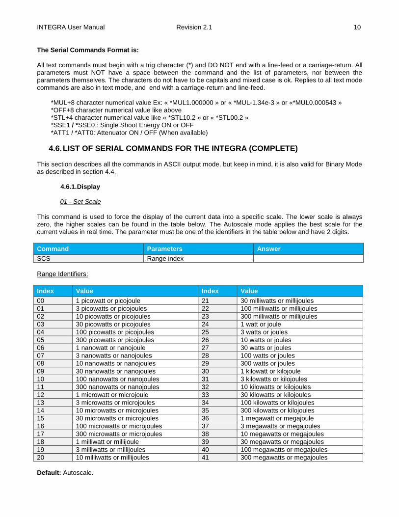
The Serial Commands Format is: All text commands must begin with a trig character (*) and DO NOT end with a line-feed or a carriage-return. All parameters must NOT have a space between the command and the list of parameters, nor between the parameters themselves. The characters do not have to be capitals and mixed case is ok. Replies to all text mode commands are also in text mode, and end with a carriage-return and line-feed.
*MUL+8 character numerical value Ex: « *MUL1.000000 » or « *MUL-1.34e-3 » or «*MUL0.000543 » *OFF+8 character numerical value like above *STL+4 character numerical value like « *STL10.2 » or « *STL00.2 » *SSE1 / *SSE0 : Single Shoot Energy ON or OFF *ATT1 / *ATT0: Attenuator ON / OFF (When available)
4.6. LIST OF SERIAL COMMANDS FOR THE INTEGRA (COMPLETE) This section describes all the commands in ASCII output mode, but keep in mind, it is also valid for Binary Mode as described in section 4.4.
4.6.1. Display
01 - Set Scale
This command is used to force the display of the current data into a specific scale. The lower scale is always zero, the higher scales can be found in the table below. The Autoscale mode applies the best scale for the current values in real time. The parameter must be one of the identifiers in the table below and have 2 digits.
Command Parameters Answer
SCS Range index
Range Identifiers:
Index Value Index Value
00 1 picowatt or picojoule 21 30 milliwatts or millijoules
01 3 picowatts or picojoules 22 100 milliwatts or millijoules
02 10 picowatts or picojoules 23 300 milliwatts or millijoules
03 30 picowatts or picojoules 24 1 watt or joule
04 100 picowatts or picojoules 25 3 watts or joules
05 300 picowatts or picojoules 26 10 watts or joules
06 1 nanowatt or nanojoule 27 30 watts or joules
07 3 nanowatts or nanojoules 28 100 watts or joules
08 10 nanowatts or nanojoules 29 300 watts or joules
09 30 nanowatts or nanojoules 30 1 kilowatt or kilojoule
10 100 nanowatts or nanojoules 31 3 kilowatts or kilojoules
11 300 nanowatts or nanojoules 32 10 kilowatts or kilojoules
12 1 microwatt or microjoule 33 30 kilowatts or kilojoules
13 3 microwatts or microjoules 34 100 kilowatts or kilojoules
14 10 microwatts or microjoules 35 300 kilowatts or kilojoules
15 30 microwatts or microjoules 36 1 megawatt or megajoule
16 100 microwatts or microjoules 37 3 megawatts or megajoules
17 300 microwatts or microjoules 38 10 megawatts or megajoules
18 1 milliwatt or millijoule 39 30 megawatts or megajoules
19 3 milliwatts or millijoules 40 100 megawatts or megajoules
20 10 milliwatts or millijoules 41 300 megawatts or megajoules
Default: Autoscale.
INTEGRA User Manual Revision 2.1 11
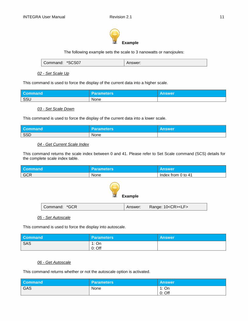
Example
The following example sets the scale to 3 nanowatts or nanojoules:
Command: *SCS07 Answer:
02 - Set Scale Up
This command is used to force the display of the current data into a higher scale.
Command Parameters Answer
SSU None
03 - Set Scale Down
This command is used to force the display of the current data into a lower scale.
Command Parameters Answer
SSD None
04 - Get Current Scale Index
This command returns the scale index between 0 and 41. Please refer to Set Scale command (SCS) details for the complete scale index table.
Command Parameters Answer
GCR None Index from 0 to 41
Example
Command: *GCR Answer: Range: 10<CR><LF>
05 - Set Autoscale
This command is used to force the display into autoscale.
Command Parameters Answer
SAS 1: On 0: Off
06 - Get Autoscale This command returns whether or not the autoscale option is activated.
Command Parameters Answer
GAS None 1: On 0: Off
INTEGRA User Manual Revision 2.1 12
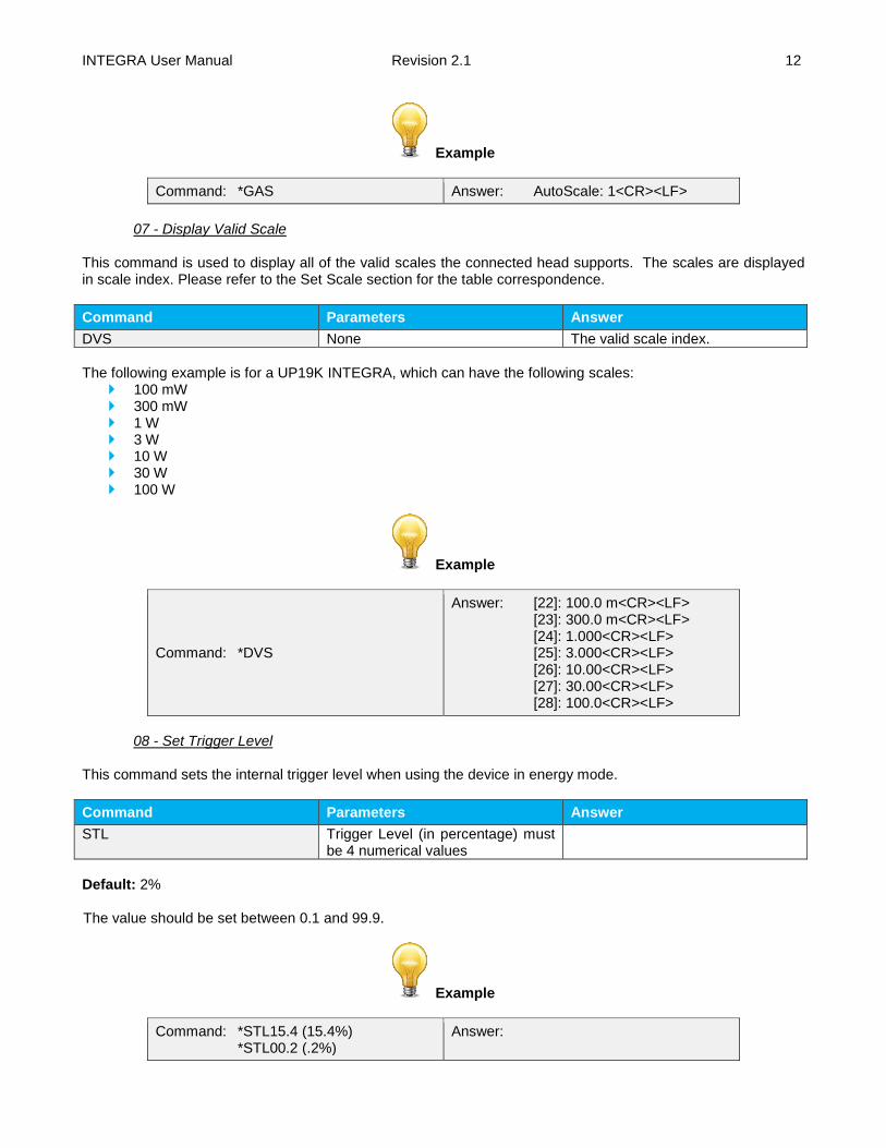
Example
Command: *GAS Answer: AutoScale: 1<CR><LF>
07 - Display Valid Scale
This command is used to display all of the valid scales the connected head supports. The scales are displayed in scale index. Please refer to the Set Scale section for the table correspondence.
Command Parameters Answer
DVS None The valid scale index.
The following example is for a UP19K INTEGRA, which can have the following scales:
100 mW 300 mW 1 W 3 W 10 W 30 W 100 W
Example
Command: *DVS
Answer: [22]: 100.0 m<CR><LF> [23]: 300.0 m<CR><LF> [24]: 1.000<CR><LF> [25]: 3.000<CR><LF> [26]: 10.00<CR><LF> [27]: 30.00<CR><LF> [28]: 100.0<CR><LF>
08 - Set Trigger Level
This command sets the internal trigger level when using the device in energy mode.
Command Parameters Answer
STL Trigger Level (in percentage) must be 4 numerical values
Default: 2% The value should be set between 0.1 and 99.9.
Example
Command: *STL15.4 (15.4%) *STL00.2 (.2%)
Answer:
INTEGRA User Manual Revision 2.1 13
09 - Get Trigger Level
This command returns the trigger level in %. The value is between 0.1% and 99.9%. This is for joulemeters and wattmeters in Energy mode only.
Command Parameters Answer
GTL None Returns the trigger level in %.
Example
Command: *GTL
Answer (original series 1.00.00): 2.0<CR><LF> Answer (new series): Trigger Level: 2.0<CR><LF>
10 – Get Measure Mode Display
This command returns the INTEGRA’s measurement mode. Depending on the head, it can be Power Mode in W, Energy Mode in J or Single Shot Energy Mode in J (SSE).
Command Parameters Answer
GMD None POWER = 0 ENERGY = 1 SSE = 2
Example
Command: *GMD Answer: Mode: 0<CR><LF>
4.6.2. Data Acquisition
11 - Query Current Value This command is used to query the value that is currently being displayed by the monitor. The value is displayed in watts or in joules.
Command Parameters Answer
CVU None Data in ASCII (Scientific notation with the new series only)
INTEGRA User Manual Revision 2.1 14
Examples
For example, with the original series v1.00.00, a 8.002557 microwatts reading would be displayed like this:
Command: *CVU Answer: 8.002557e-06<CR><LF>
For example, with the new series, a 506.601 watts reading and a -12.25631 milliwatts reading
would be displayed like this:
Command: *CVU Answer: +5.066010e+02<CR><LF>
Command: *CVU Answer: -1.225631e-02<CR><LF>
12 - Send Continuous Transmission of Data
This command is used to send data to the serial port according to the data sampling setting.
Command Parameters Answer
CAU None Data in ASCII (Scientific notation with the new series)
Examples
For example, with a wattmeter, a reading around 500 milliwatts would be displayed like this until the command *CSU is sent:
Command: *CAU
Answer (original series v1.00.00): 0.5066010<CR><LF> 0.5066012<CR><LF> 0.5066014<CR><LF> 0.5066022<CR><LF> 0.5066032<CR><LF> 0.5066042<CR><LF> …
Answer (new series): +5.066010e-01<CR><LF> +5.066012e-01<CR><LF> +5.066014e-01<CR><LF> +5.066022e-01<CR><LF> +5.066032e-01<CR><LF> +5.066042e-01<CR><LF> …
In the original series v1.00.00, the joulemeters and photodiodes also use the scientific notation. For example,
with a joulemeter, a reading around 500 millijoules would be displayed like this until the command *CSU is sent:
Command: *CAU
Answer (original series v1.00.00): 5.066010e-01<CR><LF> 5.066012e-01<CR><LF> 5.066014e-01<CR><LF> 5.066022e-01<CR><LF> 5.066032e-01<CR><LF> 5.066042e-01<CR><LF> …
Answer (new series): +5.066010e-01<CR><LF> +5.066012e-01<CR><LF> +5.066014e-01<CR><LF> +5.066022e-01<CR><LF> +5.066032e-01<CR><LF> +5.066042e-01<CR><LF> …

INTEGRA User Manual Revision 2.1 15
13 - Send Continuous Value with Frequency INTEGRA will send continuous energy data and the pulse repetition rate in Hz. They are comma separated. This is for joulemeters only.
Command Parameters Answer
CEU None Continuous value with pulse repetition rate in Hz
Example
This example is for a 32 Hz laser:
Command: *CEU
Answer (original series v1.00.00): 5.066010e-01,32.0<CR><LF> 5.066012e-01,32.0<CR><LF> 5.066015e-01,32.0<CR><LF> 5.066021e-01,32.0<CR><LF> …
Answer (new series): +5.066010e-01,32.0<CR><LF> +5.066012e-01,32.0<CR><LF> +5.066015e-01,32.0<CR><LF> +5.066021e-01,32.0<CR><LF> …
14 - Sent Current Value with Frequency
INTEGRA will send the current measurement and the pulse repetition rate in Hz. They are comma separated. This is for joulemeters only.
Command Parameters Answer
CTU None Current value with pulse repetition rate in Hz
Example
This example is for a 32 Hz laser:
Command: *CTU
Answer (original series v1.00.00): 5.066E-01,32.0<CR><LF> Answer (new series): +5.066010e-01,32.0<CR><LF>
15 - Stop the CAU Command
This command is used to stop the real time transfer enabled by the CAU and CEU commands.
Command Parameters Answer
CSU None
INTEGRA User Manual Revision 2.1 16
16 - Get Laser Frequency This command is used to get the laser frequency. This is for joulemeters only.
Command Parameters Answer
GRR None Data in ASCII
17 - Set Binary Joulemeter Mode
This command is used to set the monitor in binary or ASCII mode. Refer to section 4.4 for the INTEGRA binary mode description. This is for joulemeters only.
Command Parameters Answer
SS1 0= ASCII 1= Binary
Example
Command: *SS11 Answer:
18 - Get Binary Joulemeter Mode
This command returns whether or not the binary joulemeter mode is activated for serial communication. Refer to section 4.4 for the INTEGRA binary mode description. This is for joulemeters only.
Command Parameters Answer
GBM None 1: On 0: Off
Example
Command: *GBM Answer: Binary Joulemeter Mode: 0<CR><LF>
4.6.3. Setup
19 - Set Personal Wavelength Correction
This command is used to specify the wavelength in nm being used on the detector. The EEPROM in the detector contains measured spectral data for a wide range of wavelengths. A valid value is set between the lowest and highest wavelengths supported by the device, and it should not be a floating point value. The input parameter must have 5 digits. If the desired wavelength does not have 5 digits you must enter a zero-padded number. For example, to set the wavelength at 514 nm, you must enter 00514. In the new series, specifying zero as a wavelength or providing an out-of-bound value as a parameter cancels the command. In the original series v1.00.00, the closest valid value is used when an out-of-bound wavelength is provided.
INTEGRA User Manual Revision 2.1 17
Command Parameters Answer
PWC Wavelength
Default: Calibration wavelength, (typically 1064 nm, varies with the detector model)
Example
The following example sets the wavelength to 1550 nm.
Command: *PWC01550 Answer:
20 - Get Wavelength
This command returns the wavelength in nm.
Command Parameters Answer
GWL None Returns the wavelength in nm
Example
Command: *GWL Answer: PWC: 1064<CR><LF>
4.6.4. Control
21 - Set Anticipation
This command is used to enable or disable the anticipation processing when the device is reading from a wattmeter. The anticipation is a software-based acceleration algorithm that provides faster readings using the detector’s calibration.
Command Parameters Answer
ANT 1: On 0: Off
Default: On
Example
The following example sets the anticipation On.
Command: *ANT1 Answer:
22 - Get Anticipation Status
This command returns the anticipation status. If the anticipation is not available, it will always be at “off”.
Command Parameters Answer
INTEGRA User Manual Revision 2.1 18
GAN None 1: On 0: Off
Example
Command: *GAN Answer: Anticipation: 0<CR><LF>
23 - Noise Suppression
Sets or Queries the sampling size of the noise suppression. For pyroelectric detectors and UM detectors only. The INTEGRA Joulemeter Instrument has a special proprietary algorithm that can lower the noise-induced error when reading low energy levels, or energy readings of any level with noise present. This feature greatly reduces the effect of noise on the peak-to-peak measurement in Joulemeter mode. INTEGRA will need to measure the number of pulses selected in the Sampling Size before the algorithm will settle to the noise suppressed value. Once the readings have stabilized, any subsequent reading will be stable until the Sampling Size is changed. The system will then stabilize to the new value. Larger sampling sizes will result in more noise suppression. Noise suppression works best with the external trigger. This function will greatly improve the accuracy of the lowest scale or in any scale when used in a noisy environment.
Command Parameters Answer
AVG### ###: average size
Example
The following example sets the sampling size to 16 pulses.
Command: *AVG016 Answer: Ok.<CR><LF>
24 - Set Zero Offset
This command subtracts the current value from all future measurements the moment the command is issued to set a new zero point.
Command Parameters Answer
SOU None Autoscale: Please Wait… Done! Fixed scale:
INTEGRA User Manual Revision 2.1 19
Example (when in AutoScale)
Command: *SOU Answer: Please Wait…<CR><LF> Done!<CR><LF>
25 - Clear Zero Offset
This command undoes the Zero Offset command to set the zero point at zero.
Command Parameters Answer
COU None
26 - Get Zero Offset
This command returns whether the zero offset has been activated or not.
Command Parameters Answer
GZO None 1: On 0: Off
Example
Command: *GZO Answer: Zero: 0<CR><LF>
27 - Set Diode Zero Offset
This command subtracts the current value for all available scales from all future measurements the moment the command is issued to set a new zero point. This is for photodiodes only.
Command Parameters Answer
SDZ None Autoscale: Please Wait… Done! Fixed scale:
Example (when in AutoScale)
Command: *SDZ Answer: Please Wait…<CR><LF> Done!<CR><LF>
28 - Set User Multiplier
This command is used to set the value of the multipliers.
Command Parameters Answer
MUL 8-character numerical value
INTEGRA User Manual Revision 2.1 20
Default: 1
Example
The following example sets multiplier = 33
Command: *MUL00000033 Or *MUL3.3000e1
Answer:
29 - Get User Multiplier
This command returns the multiplier value.
Command Parameters Answer
GUM None Current multiplier value
Example
Command: *GUM Answer : User Multiplier: 1.0000000E+00<CR><LF>
30 - Set User Offset
This command is used to set the value of the offset.
Command Parameters Answer
OFF 8-character numerical value
Default: 0
Example
The following example sets the offset to 1.5 milliwatts or 1.5 millijoules.
Command: *OFF0.001500 or *OFF1.500e-3
Answer:
The other option available is the Zero Offset. The Zero Offset operation is done first, before the User Multipliers and Offsets
31 - Get User Offset This command returns the offset value.
Command Parameters Answer
INTEGRA User Manual Revision 2.1 21
GUO None Current offset value
Example
Command: *GUO Answer : User Offset: 1.5000000E-03<CR><LF>
32 - Set Single Shot Energy Mode
This command is used to toggle to Single Shot Energy Mode when using a wattmeter. It is recommended to wait at least 2 seconds after this command before sending another command, to avoid communication problems.
Command Parameters Answer
SSE 1: On 0: Off
Default: Off
33 - Set Attenuator This command is used to adjust the processing of the monitor with the readings of the head, depending on whether the head is using an external attenuator or not.
Command Parameters Answer
ATT 1: On 0: Off
Default: Off
Example
The following example sets the attenuator On, this means that the attenuator in on the detector:
Command: *ATT1 Answer:
34 - Get Attenuator
This command returns the attenuator status. If the attenuator is not available, it will always be off.
Command Parameters Answer
GAT None 1: On 0: Off
Example
Command: *GAT Answer: Attenuator: 0<CR><LF>
INTEGRA User Manual Revision 2.1 22
4.6.5. Instrument and Detector Information
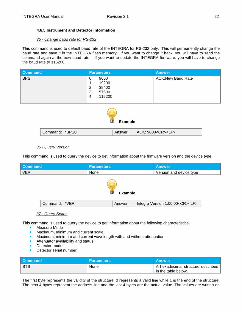
35 - Change baud rate for RS-232
This command is used to default baud rate of the INTEGRA for RS-232 only. This will permanently change the baud rate and save it in the INTEGRA flash memory. If you want to change it back, you will have to send the command again at the new baud rate. If you want to update the INTEGRA firmware, you will have to change the baud rate to 115200.
Command Parameters Answer
BPS 0 9600 1 19200 2 38400 3 57600 4 115200
ACK:New Baud Rate
Example
Command: *BPS0 Answer: ACK: 9600<CR><LF>
36 - Query Version This command is used to query the device to get information about the firmware version and the device type.
Command Parameters Answer
VER None Version and device type
Example
Command: *VER Answer: Integra Version 1.00.00<CR><LF>
37 - Query Status
This command is used to query the device to get information about the following characteristics:
Measure Mode Maximum, minimum and current scale Maximum, minimum and current wavelength with and without attenuation Attenuator availability and status Detector model Detector serial number
Command Parameters Answer
STS None A hexadecimal structure described in the table below.
The first byte represents the validity of the structure: 0 represents a valid line while 1 is the end of the structure. The next 4 bytes represent the address line and the last 4 bytes are the actual value. The values are written on
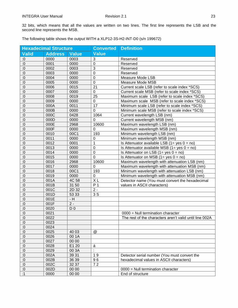
INTEGRA User Manual Revision 2.1 23
32 bits, which means that all the values are written on two lines. The first line represents the LSB and the second line represents the MSB. The following table shows the output WITH a XLP12-3S-H2-INT-D0 (s/n 199672)
Hexadecimal Structure Converted Value
Definition
Valid Address Value :0 0000 0003 3 Reserved
:0 0001 0000 0 Reserved
:0 0002 0003 3 Reserved
:0 0003 0000 0 Reserved
:0 0004 0000 0 Measure Mode LSB
:0 0005 0000 0 Measure Mode MSB
:0 0006 0015 21 Current scale LSB (refer to scale index *SCS)
:0 0007 0000 0 Current scale MSB (refer to scale index *SCS)
:0 0008 0019 25 Maximum scale LSB (refer to scale index *SCS)
:0 0009 0000 0 Maximum scale MSB (refer to scale index *SCS)
:0 000A 0011 17 Minimum scale LSB (refer to scale index *SCS)
:0 000B 0000 0 Minimum scale MSB (refer to scale index *SCS)
:0 000C 0428 1064 Current wavelength LSB (nm)
:0 000D 0000 0 Current wavelength MSB (nm)
:0 000E 2968 10600 Maximum wavelength LSB (nm)
:0 000F 0000 0 Maximum wavelength MSB (nm)
:0 0010 00C1 193 Minimum wavelength LSB (nm)
:0 0011 0000 0 Minimum wavelength MSB (nm)
:0 0012 0001 1 Is Attenuator available LSB (1= yes 0 = no)
:0 0013 0000 0 Is Attenuator available MSB (1= yes 0 = no)
:0 0014 0000 0 Is Attenuator on LSB (1= yes 0 = no)
:0 0015 0000 0 Is Attenuator on MSB (1= yes 0 = no)
:0 0016 2968 10600 Maximum wavelength with attenuation LSB (nm)
:0 0017 0000 0 Maximum wavelength with attenuation MSB (nm)
:0 0018 00C1 193 Minimum wavelength with attenuation LSB (nm)
:0 0019 0000 0 Minimum wavelength with attenuation MSB (nm)
:0 001A 4C 58 X L Detector name (You must convert the hexadecimal values in ASCII characters) :0 001B 31 50 P 1
:0 001C 2D 32 2 -
:0 001D 53 33 3 S
:0 001E - H
:0 001F 2 -
:0 0020 D 0
:0 0021 0000 = Null termination character
:0 0022 The rest of the characters aren’t valid until line 002A
:0 0023
:0 0024
:0 0025 40 03 @
:0 0026 00 1A
:0 0027 00 00
:0 0028 E1 20 á
:0 0029 00 3A :
:0 002A 39 31 1 9 Detector serial number (You must convert the hexadecimal values in ASCII characters) :0 002B 36 39 9 6
:0 002C 32 37 7 2
:0 002D 00 00 0000 = Null termination character
:1 0000 00 00 End of structure
INTEGRA User Manual Revision 2.1 24
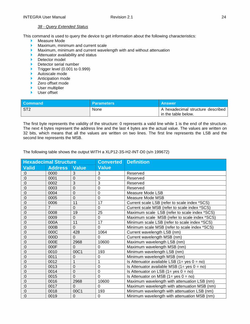
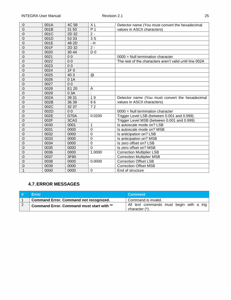
38 - Query Extended Status This command is used to query the device to get information about the following characteristics:
Measure Mode Maximum, minimum and current scale Maximum, minimum and current wavelength with and without attenuation Attenuator availability and status Detector model Detector serial number Trigger level (0.001 to 0.999) Autoscale mode Anticipation mode Zero offset mode User multiplier User offset
Command Parameters Answer
ST2 None A hexadecimal structure described in the table below.
The first byte represents the validity of the structure: 0 represents a valid line while 1 is the end of the structure. The next 4 bytes represent the address line and the last 4 bytes are the actual value. The values are written on 32 bits, which means that all the values are written on two lines. The first line represents the LSB and the second line represents the MSB. The following table shows the output WITH a XLP12-3S-H2-INT-D0 (s/n 199672)
Hexadecimal Structure Converted Value
Definition
Valid Address Value :0 0000 3 3 Reserved
:0 0001 0 0 Reserved
:0 0002 3 3 Reserved
:0 0003 0 0 Reserved
:0 0004 0 0 Measure Mode LSB
:0 0005 0 0 Measure Mode MSB
:0 0006 11 17 Current scale LSB (refer to scale index *SCS)
:0 7 0 0 Current scale MSB (refer to scale index *SCS)
:0 0008 19 25 Maximum scale LSB (refer to scale index *SCS)
:0 0009 0 0 Maximum scale MSB (refer to scale index *SCS)
:0 000A 11 17 Minimum scale LSB (refer to scale index *SCS)
:0 000B 0 0 Minimum scale MSB (refer to scale index *SCS)
:0 000C 428 1064 Current wavelength LSB (nm)
:0 000D 0 0 Current wavelength MSB (nm)
:0 000E 2968 10600 Maximum wavelength LSB (nm)
:0 000F 0 0 Maximum wavelength MSB (nm)
:0 0010 00C1 193 Minimum wavelength LSB (nm)
:0 0011 0 0 Minimum wavelength MSB (nm)
:0 0012 1 1 Is Attenuator available LSB (1= yes 0 = no)
:0 0013 0 0 Is Attenuator available MSB (1= yes 0 = no)
:0 0014 0 0 Is Attenuator on LSB (1= yes 0 = no)
:0 0015 0 0 Is Attenuator on MSB (1= yes 0 = no)
:0 0016 2968 10600 Maximum wavelength with attenuation LSB (nm)
:0 0017 0 0 Maximum wavelength with attenuation MSB (nm)
:0 0018 00C1 193 Minimum wavelength with attenuation LSB (nm)
:0 0019 0 0 Minimum wavelength with attenuation MSB (nm)
INTEGRA User Manual Revision 2.1 25
:0 001A 4C 58 X L Detector name (You must convert the hexadecimal values in ASCII characters) :0 001B 31 50 P 1
:0 001C 2D 32 2 -
:0 001D 53 33 3 S
:0 001E 48 2D - H
:0 001F 2D 32 2 -
:0 0020 30 44 D 0
:0 0021 0 0 0000 = Null termination character
:0 0022 0 0 The rest of the characters aren’t valid until line 002A
:0 0023 0 0
:0 0024 1F 0
:0 0025 40 3 @
:0 0026 0 1A
:0 0027 0 0
:0 0028 E1 20 Á
:0 0029 0 3A :
:0 002A 39 31 1 9 Detector name (You must convert the hexadecimal values in ASCII characters) :0 002B 36 39 9 6
:0 002C 32 37 7 2
:0 002D 0 0 0000 = Null termination character
:0 002E D70A 0.0200 Trigger Level LSB (between 0.001 and 0.999)
:0 002F 3CA3 Trigger Level MSB (between 0.001 and 0.999)
:0 0030 0001 1 Is autoscale mode on? LSB
:0 0031 0000 0 Is autoscale mode on? MSB
:0 0032 0000 0 Is anticipation on? LSB
:0 0033 0000 0 Is anticipation on? MSB
:0 0034 0000 0 Is zero offset on? LSB
:0 0035 0000 0 Is zero offset on? MSB
:0 0036 0000 1.0000 Correction Multiplier LSB
:0 0037 3F80 Correction Multiplier MSB
:0 0038 0000 0.0000 Correction Offset LSB
:0 0039 0000 Correction Offset MSB
:1 0000 0000 0 End of structure
4.7. ERROR MESSAGES
# Error Comment
1 Command Error. Command not recognized. Command is invalid.
2 Command Error. Command must start with '*' All text commands must begin with a trig character (*).

INTEGRA User Manual Revision 2.1 26
5. USB DRIVER INSTALLATION
INTEGRA USB drivers will install a virtual COM port on your PC. Please download the USB driver at: https://gentec-eo.com/downloads.
1. Do not connect the INTEGRA to your computer
2. Choose the appropriate operating system corresponding to your computer
3. Follow the installation steps until you have the message INTEGRA ready to use.
4. You can now connect the INTEGRA and install the software.

INTEGRA User Manual Revision 2.1 27
6. MAINTENANCE
6.1. FREE SOFTWARE UPGRADE Keep up to date with the latest versions of PC-Gentec-EO software to get the new features and options. As new and improved versions of the device's firmware are created, it is in your best interest to update your INTEGRA. The latest device firmware can be downloaded from the Gentec-EO website at https://gentec-eo.com/downloads. Go to the Downloads section. Find the file that corresponds to your INTEGRA and follow our simple, easy to use instructions.
6.2. TROUBLESHOOTING When using the INTEGRA with serial commands, please ensure to always close the communication port after you are done using the INTEGRA. If you do not do so, the INTEGRA will not be recognized the next time you connect it to the computer.
INTEGRA User Manual Revision 2.1 28
7. DECLARATION OF CONFORMITY
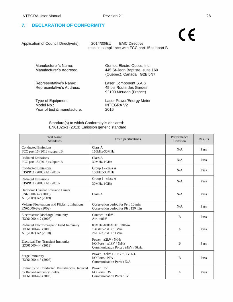
Application of Council Directive(s): 2014/30/EU EMC Directive
tests in compliance with FCC part 15 subpart B
Manufacturer’s Name: Gentec Electro Optics, Inc. Manufacturer’s Address: 445 St-Jean Baptiste, suite 160
(Québec), Canada G2E 5N7 Representative’s Name: Laser Component S.A.S Representative’s Address: 45 bis Route des Gardes 92190 Meudon (France) Type of Equipment: Laser Power/Energy Meter Model No.: INTEGRA V2 Year of test & manufacture: 2016
Standard(s) to which Conformity is declared: EN61326-1 (2013) Emission generic standard
Test Name
Standards Test Specifications
Performance
Criterion Results
Conducted Emissions
FCC part 15 (2013) subpart B
Class A
150kHz-30MHz N/A Pass
Radiated Emissions
FCC part 15 (2013) subpart B
Class A
30MHz-1GHz N/A Pass
Conducted Emissions
CISPR11 (2009) A1 (2010)
Group 1 - class A
150kHz-30MHz N/A Pass
Radiated Emissions
CISPR11 (2009) A1 (2010)
Group 1 - class A
30MHz-1GHz N/A Pass
Harmonic Current Emission Limits
EN61000-3-2 (2006)
A1 (2009) A2 (2009)
Class A N/A Pass
Voltage Fluctuations and Flicker Limitations
EN61000-3-3 (2008)
Observation period for Pst : 10 min
Observation period for Plt : 120 min N/A Pass
Electrostatic Discharge Immunity
IEC61000-4-2 (2008)
Contact : ±4kV
Air : ±8kV B Pass
Radiated Electromagnetic Field Immunity
IEC61000-4-3 (2006)
A1 (2007) A2 (2010)
80MHz-1000MHz : 10V/m
1.4GHz-2GHz : 3V/m
2GHz-2.7GHz : 1V/m
A Pass
Electrical Fast Transient Immunity
IEC61000-4-4 (2012)
Power : ±2kV / 5kHz
I/O Ports : ±1kV / 5kHz
Communication Ports : ±1kV / 5kHz
B Pass
Surge Immunity
IEC61000-4-5 (2005)
Power : ±2kV L-PE / ±1kV L-L
I/O Ports : N/A
Communication Ports : N/A
B Pass
Immunity to Conducted Disturbances, Induced
by Radio-Frequency Fields
IEC61000-4-6 (2008)
Power : 3V
I/O Ports : 3V
Communication Ports : 3V
A Pass

INTEGRA User Manual Revision 2.1 29
Test Name
Standards Test Specifications
Performance
Criterion Results
Voltage Dips, Short Interruptions and Voltage
Variation Immunity on AC Input
IEC61000-4-11 (2004)
Voltage dips :
0% during 1 cycle
40% during 10 cycles
70% during 25 cycles
Short interruptions :
0% during 250 cycles
B
C
C
C
Pass
I, the undersigned, hereby declare that the equipment specified above
conforms to the above Directive(s) and Standard(s)
Place: Quebec (Quebec)
Date : July 15, 2016
(President)

INTEGRA User Manual Revision 2.1 30
APPENDIX A: WEEE DIRECTIVE
Recycling and Separation Procedure for WEEE Directive 2002/96/EC
This section is used by the recycling center when the monitor reaches its end of life. Breaking the calibration seal or opening the monitor will void the INTEGRA warranty. For the head please refer to the head’s manual. The complete Monitor contains
1 Monitor 1 USB cable
Separation
Plastic: INTEGRA enclosure. Printed circuit board: inside the INTEGRA (no need to separate less than 10 cm
2)

INTEGRA User Manual Revision 2.1 31