integral feedback control of a self-sensing ... · integral feedback control of a self-sensing...
TRANSCRIPT

IOP PUBLISHING SMART MATERIALS AND STRUCTURES
Smart Mater. Struct. 16 (2007) 1098–1108 doi:10.1088/0964-1726/16/4/019
Integral feedback control of a self-sensingmagnetostrictive actuatorK Kuhnen, M Schommer and H Janocha
Laboratory for Process Automation (LPA), Saarland University, Building 13,D-66123 Saarbruecken, Germany
E-mail: [email protected]
Received 8 March 2007Published 25 June 2007Online at stacks.iop.org/SMS/16/1098
AbstractAn essential reason for the increasing interest in magnetostrictive materials isthe capability to perform sensing and actuation at the same time and in thesame place. With these inherent sensory capabilities, the material can adoptboth sensing and actuation functions in mechatronic systems. Operating inthis way, these solid-state transducers are frequently termed ‘self-sensingactuators’. They support a miniaturized, simpler and cheaper mechatronicsystem design and are therefore regarded as a key technology in the 21stcentury. A central task in the development of the self-sensingmagnetostrictive actuator was the separation of the sensing information fromthe actuation information contained in the magnetic flux measurement signal.In practice, however, due to the high input amplitudes undesired complexhysteresis and saturation nonlinearities appear, which make a separation ofsensing information from actuation information with linear actuator modelsimpossible. Therefore, a novel signal processing method based on hysteresisoperators was applied to the self-sensing magnetostrictive actuator. Thismethod allowed the compensation of these nonlinearities in real-time andwith it a linearization and decoupling of sensor and actuator operation.
The focus of the present paper is the combination of the operator-basedsignal processing concept with an integral feedback controller, which resultsin a so-called integral feedback controlled self-sensing magnetostrictiveactuator. This control type is capable of compensating hysteresis effects aswell as disturbances resulting from the limited actuator stiffness without theneed for an external displacement or force sensor. The sensor informationthat is required by the integral feedback controller to guarantee the describedfunctionality is gained solely via the inherent sensory properties of theactuator material. In this way, the integral feedback controlled self-sensingmagnetostrictive actuator can be treated as an optimized component forpositioning systems, vibration dampers and valve drives, for example inaeronautic and automotive applications.
1. Introduction
Rods of magnetostrictive materials have been found inindustrial use in the form of actuators for many years dueto their ability to convert electrical into mechanical energy.As shown in figure 1 a coil is located around the rodwhich produces the necessary magnetic field H for actuationoperation. To achieve a defined magnetic field H , thecoil is driven with a corresponding current I . Due to the
magnetostrictive effect in the material, the rod produces adisplacement s against the surrounded mechanical structure.Magnetically the rod reacts with a current-dependent variationof its magnetic flux φ. Due to the current-dependentdisplacement, the surrounding mechanical structure reactswith a force F against the rod. In addition to the current-dependent displacement and magnetic flux variation this forceproduces an additional force-dependent displacement due tothe elasticity of the material and an additional force-dependent
0964-1726/07/041098+11$30.00 © 2007 IOP Publishing Ltd Printed in the UK 1098

Integral feedback control of a self-sensing magnetostrictive actuator
Figure 1. Principal structure of a magnetostrictive actuator.
magnetic flux variation due to the so-called Villary effect. Thelatter effect forms the basis for the inherent sensory capabilityof the magnetostrictive material.
1.1. Application example: magnetostrictive valve for commonrail diesel injection systems
As magnetostrictive actuators produce high forces at highfrequencies, they are used in dynamically demandingapplications. Common rail diesel injection systems are acurrent example. Due to stricter laws about exhaust gasemission, new injection methods have been developed, whichreduce fuel consumption and the emission of toxic gasesof diesel engines. The entire injection process is therebydivided into several partial injections. The pilot injectionwith extremely small injection quantities reduces the noiseemission. The main injection delivers the quantity of fuelrequired for the combustion process and can again be dividedinto several injection phases. The evolving soot is recombustedwithin the cylinder during the post-injection, and so theparticulate emission is reduced. Since the exhaust gascomposition is closely linked to the accuracy of injectiontime and injection quantity, one must adhere strictly to thegiven parameters. The injection pressure, injection timeand fuel dosage are important variables. Highly dynamicactuators are required in order to achieve the demanded quickresponse time over the entire revolution speed range of theengine. Electromagnetic injection valves do not meet thoserequirements. Solid-state actuators represent an alternative astheir dynamic behaviour is much better than the behaviourof electromagnetically driven valves. Whereas today mainlypiezoelectric actuators are used, there exist a small numberof systems on the basis of magnetostrictive material [1], seefigure 2.
An exact determination of the actuator’s state couldimprove further the injection’s accuracy. But due to the
Figure 3. Magnetostrictive dynamic vibration absorber for turbopropaircraft.
extreme requirements in the field of automotive engineeringwith respect to part volume and costs, it is not always possibleto apply dedicated sensors for measuring displacement andmechanical load. By using the inherent sensor effects of solid-state actuators information about their mechanical state can becollected so displacement and load can be reconstructed duringoperation. Their evaluation allows the optimized control ofthe injection process and moreover the realization of a healthmonitoring function.
1.2. Application example: magnetostrictive dynamic vibrationabsorber for turboprop aircraft
A major issue for the internal comfort in civil transportturboprop aircraft is the reduction of the noise transmittedinside the cabin, associated to the propeller fundamentalfrequency and its first harmonics. Active noise and vibrationcontrol (ANVC) systems aim to reduce actively the noise levelin the aircraft cabin by superimposing a secondary vibrationto the primary one on the structural components belongingto the vibration transmission path. A typical countermeasureis the installation of dynamic vibration absorbers (DVAs) onthe fuselage frames. DVAs can be schematized as single-degree-of-freedom auxiliary vibrating systems, which reducethe vibration amplitude of the structure they are installedon, when their natural frequency is tuned to the disturbancefrequency. Passive DVAs demonstrated their effectiveness inreducing both vibration and noise levels in the turboprop cabin.Their main limitations were due to the necessity of being tunedto a single fixed frequency on the host structure. This kindof problem could be overcome designing a hybrid device as,for example, shown in figure 3 working as inertial passiveDVA at the main (lower) disturbing frequency (BPF) and asactive force transducer in a wider frequency band, thanks tothe magnetostrictive active member [2, 3].
Figure 2. Magnetostrictive valve for common rail diesel injection systems.
1099
K Kuhnen et al
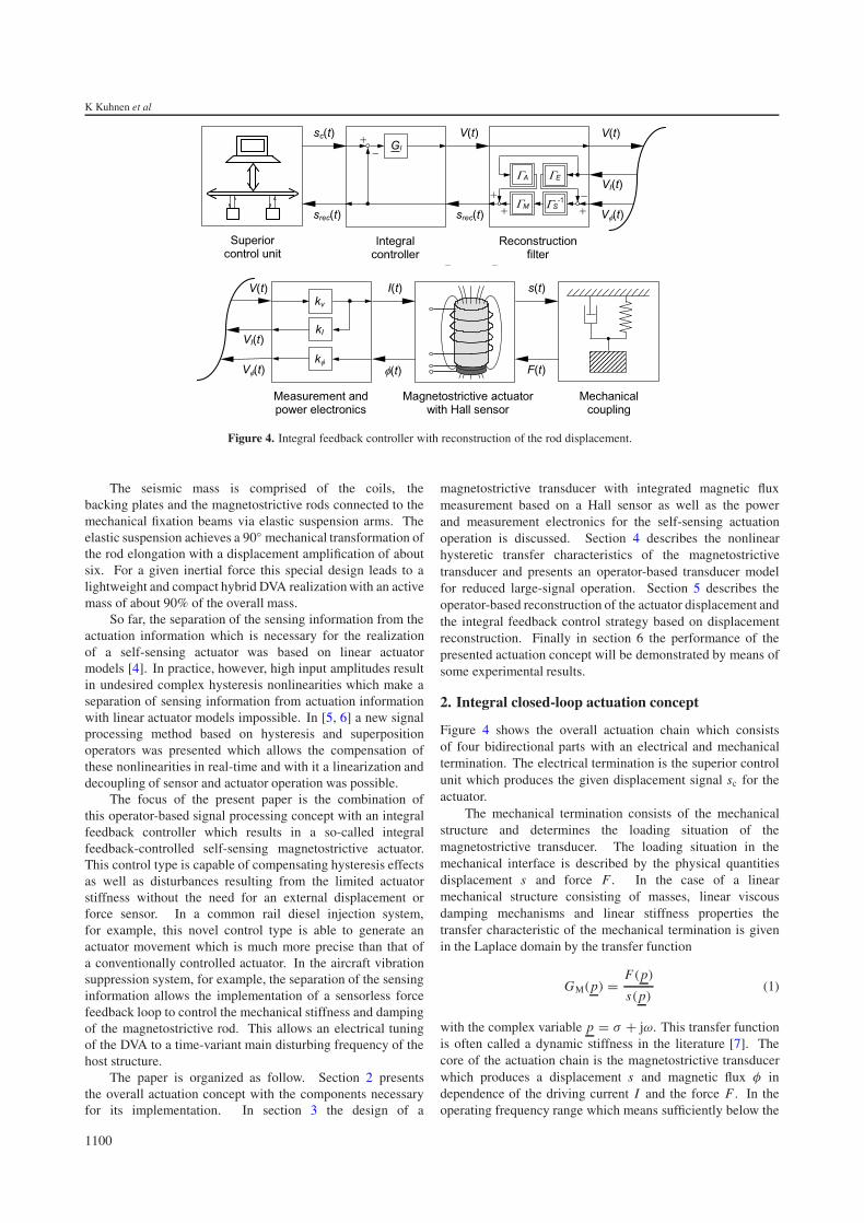
Figure 4. Integral feedback controller with reconstruction of the rod displacement.
The seismic mass is comprised of the coils, thebacking plates and the magnetostrictive rods connected to themechanical fixation beams via elastic suspension arms. Theelastic suspension achieves a 90◦ mechanical transformation ofthe rod elongation with a displacement amplification of aboutsix. For a given inertial force this special design leads to alightweight and compact hybrid DVA realization with an activemass of about 90% of the overall mass.
So far, the separation of the sensing information from theactuation information which is necessary for the realizationof a self-sensing actuator was based on linear actuatormodels [4]. In practice, however, high input amplitudes resultin undesired complex hysteresis nonlinearities which make aseparation of sensing information from actuation informationwith linear actuator models impossible. In [5, 6] a new signalprocessing method based on hysteresis and superpositionoperators was presented which allows the compensation ofthese nonlinearities in real-time and with it a linearization anddecoupling of sensor and actuator operation was possible.
The focus of the present paper is the combination ofthis operator-based signal processing concept with an integralfeedback controller which results in a so-called integralfeedback-controlled self-sensing magnetostrictive actuator.This control type is capable of compensating hysteresis effectsas well as disturbances resulting from the limited actuatorstiffness without the need for an external displacement orforce sensor. In a common rail diesel injection system,for example, this novel control type is able to generate anactuator movement which is much more precise than that ofa conventionally controlled actuator. In the aircraft vibrationsuppression system, for example, the separation of the sensinginformation allows the implementation of a sensorless forcefeedback loop to control the mechanical stiffness and dampingof the magnetostrictive rod. This allows an electrical tuningof the DVA to a time-variant main disturbing frequency of thehost structure.
The paper is organized as follow. Section 2 presentsthe overall actuation concept with the components necessaryfor its implementation. In section 3 the design of a
magnetostrictive transducer with integrated magnetic fluxmeasurement based on a Hall sensor as well as the powerand measurement electronics for the self-sensing actuationoperation is discussed. Section 4 describes the nonlinearhysteretic transfer characteristics of the magnetostrictivetransducer and presents an operator-based transducer modelfor reduced large-signal operation. Section 5 describes theoperator-based reconstruction of the actuator displacement andthe integral feedback control strategy based on displacementreconstruction. Finally in section 6 the performance of thepresented actuation concept will be demonstrated by means ofsome experimental results.
2. Integral closed-loop actuation concept
Figure 4 shows the overall actuation chain which consistsof four bidirectional parts with an electrical and mechanicaltermination. The electrical termination is the superior controlunit which produces the given displacement signal sc for theactuator.
The mechanical termination consists of the mechanicalstructure and determines the loading situation of themagnetostrictive transducer. The loading situation in themechanical interface is described by the physical quantitiesdisplacement s and force F . In the case of a linearmechanical structure consisting of masses, linear viscousdamping mechanisms and linear stiffness properties thetransfer characteristic of the mechanical termination is givenin the Laplace domain by the transfer function
GM(p) = F(p)
s(p)(1)
with the complex variable p = σ + jω. This transfer functionis often called a dynamic stiffness in the literature [7]. Thecore of the actuation chain is the magnetostrictive transducerwhich produces a displacement s and magnetic flux φ independence of the driving current I and the force F . In theoperating frequency range which means sufficiently below the
1100

Integral feedback control of a self-sensing magnetostrictive actuator
Figure 5. Magnetostrictive actuator with Hall sensor for magnetic flux measurements.
first resonant frequency of the magnetostrictive transducer thetransfer characteristic of the transducer can be assumed as rate-independent.
From this point of view the dynamic effects in theoperating frequency range of the transducer result mainly fromthe interaction between the transducer’s static stiffness and thedynamic properties of the mechanical structure. The hystereticnonlinearities are concentrated in the transducer component. Aspecial feature in the design of the magnetostrictive actuatorwhich is described in section 3 is a Hall element allowingus to measure the variation of magnetic flux with respect tothe mechanical load and the electric current. If the actuatoris operated in current-control mode, the magnetic flux inthe magnetostrictive material represents the physical variablecontaining the sensory information about the mechanicalquantities. Therefore, the quantitative knowledge about theflux is the base for a self-sensing magnetostrictive actuator.The power and measurement electronics provide a drivingcurrent I controlled by the input voltage V for actuationoperation and supply the reconstruction filter component withthe measurement voltages VI and Vφ , which contain themeasurement information of the current I and the magneticflux φ, respectively.
The reconstruction filter component extracts the displace-ment information from the measurement voltages VI and Vφ inthe form of a reconstructed displacement srec. It compensatesthe hysteretic disturbances in the measurement signals and de-couples the sensory information from the actuator informationby means of a model for the hysteretic characteristic of themagnetostrictive transducer. The integral controller componentcompares the reconstructed displacement srec with the givendisplacement sc and generates an input voltage V for the powerelectronics in such a sense that the reconstructed displacementconverges to the given displacement with time independent ofthe internal disturbance due to the hysteretic characteristic ofthe magnetostrictive transducer and independent of the exter-nal disturbance due to the finite stiffness of the magnetostric-tive transducer. Moreover, the reconstructed displacement srec
is fed back to the superior control unit for further implementa-tion of adjusting, diagnosing and controlling functions therein.
3. Magnetostrictive actuator with integratedmagnetic flux measurement
This section describes a special design of a magnetostrictiveactuator which consists of a magnetic circuit with FEM-optimized magnetic flux guiding properties, an integratedmagnetic flux measurement circuit based on a Hall sensor andan analogue power electronics for current control.
3.1. Design and construction of a magnetostrictive transducer
Magnetostrictive materials are alloys based on rare earthelements. As they are polycrystalline, the productionmethods are very similar to the methods used in siliconwafer production. The crystal slowly grows by pulling agerm out of the liquefied alloy and the material cools down,forming the magnetostrictive rod. In a second step, the finalform is achieved by grinding with diamond machine tools.Their production is very costly and therefore the price forsuch materials is very high. In respect to these costs, thedisplacement potential of a given magnetostrictive rod shouldbe used as effectively as possible. Therefore, a careful designof the flux guiding circuit is necessary. To ensure the optimaluse of the material the homogeneity of the field along therod is an important aspect. The displacement depends on themagnetic field generated by a surrounding coil. If the fieldis not optimally distributed, some regions in the material mayhave already reached their maximal elongation while otherareas could still extend if a higher field were applied. Ifthe magnetic flux guiding circuit and its coil are carefullydesigned, e.g. with a FEM tool, these inhomogeneities onlyoccur to a small amount and do not influence the performanceof the complete actuator notably.
Due to their quite low permeability of about μr =5, . . . , 10 magnetostrictive materials are not suited for fluxguiding elements in the construction of a magnetostrictiveactuator. In fact, the surrounding structure has to ensureguiding and focusing of the magnetic field. Because of thathighly permeable iron is used for flux guidance. The lowerend of the magnetostrictive rod is a fixed mechanical referencepoint while the upper end is free to move axially. As shownin figure 5 the upper part of the fixture is freely movable
1101
K Kuhnen et al
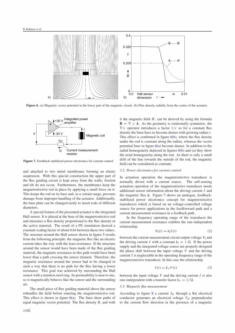
Figure 6. (a) Magnetic vector potential in the lower part of the magnetic circuit. (b) Flux density radially from the centre of the actuator.
Figure 7. Feedback-stabilized power electronics for current control.
and attached to two metal membranes forming an elasticsuspension. With this special construction the upper part ofthe flux guiding circuit is kept away from the walls; frictionand tilt do not occur. Furthermore, the membranes keep themagnetostrictive rod in place by applying a small force on it.This keeps the rod on its base and, in a certain range, preventsdamage from improper handling of the actuator. Additionally,the base plate can be changed easily to insert rods of differentdiameters.
A special feature of the presented actuator is the integratedHall sensor. It is placed at the base of the magnetostrictive rodand measures a flux density proportional to the flux density inthe active material. The result of a FE simulation showed aconstant scaling factor of about 0.64 between these two values.The structure around the Hall sensor shown in figure 5 resultsfrom the following principle: the magnetic flux like an electriccurrent takes the way with the least resistance. If the structurearound the sensor would have been made of the flux guidingmaterial, the magnetic resistance in this path would have beenlower than a path crossing the sensor element. Therefore, themagnetic resistance around the sensor had to be changed insuch a way that there is no path for the flux having a lowerresistance. This goal was achieved by surrounding the Hallsensor with a stainless steel ring. Its permeability is near to one,so it magnetically behaves like the sensor and the surroundingair.
The small piece of flux guiding material above the sensorrebundles the field before entering the magnetostrictive rod.This effect is shown in figure 6(a). The lines show paths ofequal magnetic vector potential. The flux density B, and with
it the magnetic field H , can be derived by using the formulaB = ∇ × A. As the geometry is rotationally symmetric, the∇× operator introduces a factor 1/r so for a constant fluxdensity the lines have to become denser with growing radius r .This effect is confirmed in figure 6(b), where the flux densityunder the rod is constant along the radius, whereas the vectorpotential lines in figure 6(a) become denser. In addition to theradial homogeneity depicted in figures 6(b) and (a) they showthe axial homogeneity along the rod. As there is only a smalldrift of the line towards the outside of the rod, the magneticfield can be considered as constant.
3.2. Power electronics for current control
In actuation operation the magnetostrictive transducer isnormally driven with a current source. The self-sensingactuation operation of the magnetostrictive transducer needsadditional sensor information about the driving current I andthe magnetic flux φ. Figure 7 shows an analogue, feedback-stabilized power electronics concept for magnetostrictivetransducers which is based on an voltage-controlled voltagesource for power applications in the feedforward path and acurrent measurement resistance in a feedback path.
In the frequency operating range of the transducer thecurrent measurement resistance exhibits the rate-independentrelationship
VI(t) = kI I (t) (2)
between the current measurement circuit output voltage VI andthe driving current I with a constant kI = 1 �. If the powersupply and the integrated voltage source are properly designedthe phase shift between the input voltage V and the drivingcurrent I is neglectable in the operating frequency range of themagnetostrictive transducer. In this case the relationship
I (t) = kV V (t) (3)
between the input voltage V and the driving current I is alsorate-independent with a transfer factor kV = 1/�.
3.3. Magnetic flux measurement
According to figure 8 a current IH through a flat electricalconductor generates an electrical voltage VH perpendicularto the current flow direction in the presence of a magnetic
1102

Integral feedback control of a self-sensing magnetostrictive actuator
Figure 8. Hall effect and integrated Hall sensor component KSY 13 with current source and amplification electronics.
flux density B. This effect arises from the force acting onmoving electrical charges in the presence of a magnetic fieldand is well known as the Hall effect. The sensor elementwhich is used in this work to measure the magnetic flux in amagnetostrictive rod is the ion-implanted Hall generator KSY13 from Infineon Technologies Inc. made of mono-crystallineGaAs material [8]. The active area of the miniaturized GaAschip with dimensions of 3.0 mm × 2.6 mm × 1.1 mm isapproximately 0.2 mm × 0.2 mm and is placed approximately0.3 mm below the surface of the package. If this sensor isoperated with a constant supply current IH = 5 mA, the outputvoltage VH is directly proportional to a magnetic flux densityB with a constant kH of approximately 1.2 V T−1.
Due to the homogeneous flux density distribution inthe cross-sectional area AT of the magnetostrictive rod andthe Hall sensor depicted in figure 6(b) there follows aproportional relationship between the generated Hall voltageVH and the magnetic flux φ with a constant kH kT /AT .The constant factor kT = 0.64 considers the deviation ofthe flux density amplitude between the cross-sectional areasA–A′ located at the Hall sensor and B–B′ located within themagnetostrictive rod, see figures 5 and 6(b). The diameterof the magnetostrictive rod used is 6 mm. From this followsa cross-sectional area AT of 28.3 mm2 and a proportionalconstant kH kT /AT between the magnetic flux and the Hallvoltage of approximately 0.027 V T−1 mm
−2. The magnetic
flux measurement electronics is shown in figure 8 and consistsof a constant current source for supplying the Hall sensor withthe current IH and a magnetic flux measurement circuit foramplifying the generated Hall voltage VH . This magnetic fluxmeasurement circuit buffers the potential at each output voltagepin of the Hall sensor using an impedance converter of anamplification factor 1. In the second stage of the measurementcircuit, the two output signals of the impedance converter aresubtracted with a integrated difference amplifier which hasan amplification factor of 40. In the frequency operatingrange of the transducer the Hall sensor and the magnetic flux
measurement circuit exhibit the rate-independent relationship
Vφ(t) = kφφ(t) (4)
with a constant kφ = 40kH kT /AT = 1.08 V T−1 mm−2
.
4. Large-signal modelling with scalar hysteresisoperators
According to the domain switching processes in themagnetostrictive material the transfer characteristics betweenthe electromagnetic quantities and the mechanical quantitiesare highly nonlinear with a complex rate-independent memory.The first step in modelling this behaviour for control and signalprocessing purposes consists of determining a proper magneticand mechanical operating point of the magnetostrictivetransducer.
4.1. Large-signal characteristic and operating pointdetermination
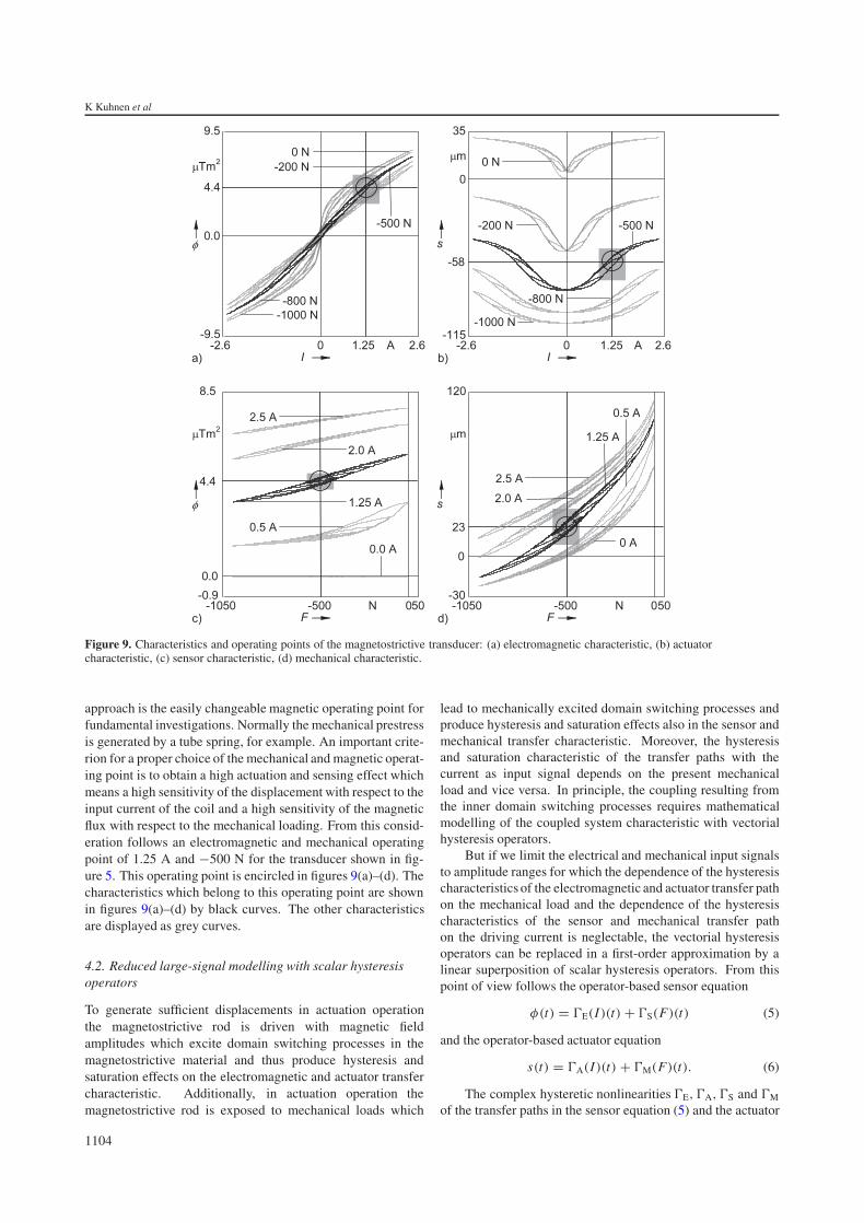
Figures 9(a)–(d) show the measured electromagnetic (φ–Irelationship), actuator (s–I relationship), sensor (φ–Frelationship) and mechanical (s–F relationship) characteristicsof the magnetostrictive transducer shown in figure 5. Incontrast to the electrical excitation the transducer cannot beloaded with tension forces due to its high porosity. Therefore, abipolar mechanical excitation assumes a mechanical prestressand thus the choice of a proper mechanical operating point.If a magnetostrictive transducer is used as an actuator thestrong monotonicity of the displacement–current characteristicis an important precondition. Therefore for bipolar electricaloperation the transducer needs a magnetic bias whichrepresents the magnetic operating point of the transducer.
The magnetic bias can be realized with permanent mag-nets or electromagnetically. When using the electromagneticmethod the static field can be generated by overlaying an off-set current in the coil. An advantage of the electromagnetical
1103
K Kuhnen et al
Figure 9. Characteristics and operating points of the magnetostrictive transducer: (a) electromagnetic characteristic, (b) actuatorcharacteristic, (c) sensor characteristic, (d) mechanical characteristic.
approach is the easily changeable magnetic operating point forfundamental investigations. Normally the mechanical prestressis generated by a tube spring, for example. An important crite-rion for a proper choice of the mechanical and magnetic operat-ing point is to obtain a high actuation and sensing effect whichmeans a high sensitivity of the displacement with respect to theinput current of the coil and a high sensitivity of the magneticflux with respect to the mechanical loading. From this consid-eration follows an electromagnetic and mechanical operatingpoint of 1.25 A and −500 N for the transducer shown in fig-ure 5. This operating point is encircled in figures 9(a)–(d). Thecharacteristics which belong to this operating point are shownin figures 9(a)–(d) by black curves. The other characteristicsare displayed as grey curves.
4.2. Reduced large-signal modelling with scalar hysteresisoperators
To generate sufficient displacements in actuation operationthe magnetostrictive rod is driven with magnetic fieldamplitudes which excite domain switching processes in themagnetostrictive material and thus produce hysteresis andsaturation effects on the electromagnetic and actuator transfercharacteristic. Additionally, in actuation operation themagnetostrictive rod is exposed to mechanical loads which
lead to mechanically excited domain switching processes andproduce hysteresis and saturation effects also in the sensor andmechanical transfer characteristic. Moreover, the hysteresisand saturation characteristic of the transfer paths with thecurrent as input signal depends on the present mechanicalload and vice versa. In principle, the coupling resulting fromthe inner domain switching processes requires mathematicalmodelling of the coupled system characteristic with vectorialhysteresis operators.
But if we limit the electrical and mechanical input signalsto amplitude ranges for which the dependence of the hysteresischaracteristics of the electromagnetic and actuator transfer pathon the mechanical load and the dependence of the hysteresischaracteristics of the sensor and mechanical transfer pathon the driving current is neglectable, the vectorial hysteresisoperators can be replaced in a first-order approximation by alinear superposition of scalar hysteresis operators. From thispoint of view follows the operator-based sensor equation
φ(t) = �E(I)(t) + �S(F)(t) (5)
and the operator-based actuator equation
s(t) = �A(I)(t) + �M(F)(t). (6)
The complex hysteretic nonlinearities �E, �A, �S and �M
of the transfer paths in the sensor equation (5) and the actuator
1104

Integral feedback control of a self-sensing magnetostrictive actuator
Figure 10. Hysteresis characteristics of the magnetostrictive actuator in the operating point for limited driving and loading amplitude ranges:(a) electromagnetic characteristic, (b) actuator characteristic, (c) sensor characteristic, (d) mechanical characteristic.
equation (6) can be modelled in a sufficiently precise way, forexample, by Preisach, Krasnosel’skii–Pokrovskii or modifiedPrandtl–Ishlinskii hysteresis operators which are described indetail in [9–12]. In the present work the modelling of thehysteretic transfer paths was carried out with the so-calledmodified Prandtl–Ishlinskii approach [9, 10].
For the magnetostrictive actuator introduced in section3.1 the electrical range of validity of the model (5) and (6)is about 30% of the electrical full amplitude range andamounts at an electrical operating point of 1.25 A to about±0.375 A. This reduced electrical operating range is shownin figures 9(a) and (b) as a light grey shaded area. Themechanical range of validity is about 50% of the mechanicalfull amplitude range and amounts at a mechanical operatingpoint of −500 N to about ±100 N. The reduced mechanicaloperating range is shown in figures 9(c) and (d) as a lightgrey shaded area. The mechanical full amplitude rangeis defined as that force amplitude which compensates thecurrent-dependent displacement of the actuator produced bymaximum current amplitudes of ±1.25 A. This force is termedthe clamping force of the actuator and amounts to ±200 Nat the given operating point. Figures 10(a)–(d) show themeasured hysteresis characteristics of the electromagnetic,actuator, sensor and mechanical transfer paths WE, WA, WS andWM as grey curves and the corresponding modified Prandtl–Ishlinskii hysteresis operators �E, �A, �S and �M as black
Table 1. Relative model errors.
Model error eE (%) eA (%) eS (%) eM (%)
I 15.03 27.55 26.95 15.13� 2.28 3.89 4.42 2.24
curves. A comparison of the relative model errors for thedifferent transfer paths, defined by
e = maxt0�t�te {|�(x)(t) − W (x)(t)|}maxt0�t�te {|�(x)(t)|} , (7)
leads to the results in table 1.The results show a reduction of the relative model error
of the operator models by about one order of magnitudein comparison to the relative model error of the best linearapproximations IE, IA, IS and IM.
5. Integral feedback control of reconstructeddisplacement
The goal of the reconstruction filter unit is to determine thepresent displacement value based only on measurement val-ues of the driving current and the magnetic flux of the magne-tostrictive transducer which means without using an externaldisplacement sensor. The corresponding reconstruction filter
1105

K Kuhnen et al
Figure 11. Hysteresis characteristics of the operators �S and itsinverse �−1
S .
equation can be derived by resolving the operator-based sensorequation (5) and integrating the result into the operator-basedactuator equation (6). From this follows
srec(t) = �A
(VI
kI
)(t) + �M
(�−1
S
(Vφ
kφ
− �E
(VI
kI
)))(t).
(8)The displacement reconstruction filter uses the modified
Prandtl–Ishlinskii hysteresis operators �A, �E, and �M of theactuator, electromagnetic and mechanical transfer paths, theinverse �−1
S of the modified Prandtl–Ishlinskii hysteresis op-erator �S of the sensor path and the measurement circuit volt-ages VI and Vφ from the power and measurement electronicsunit. Because the inverse �−1
S can determined a priori from themodel �S with the corresponding transformation laws whichare described in detail in [11, 12] the filter calculation doesnot need any numerical inversion algorithm as, for example,in the case of the Preisach or Krasnosel’skii–Pokrovskii hys-teresis modelling and compensation approach [10]. This is asignificant advantage for this special real-time signal process-ing application. The characteristic of the inverse �−1
S corre-sponding to the characteristic of �S according to figure 10(c) isshown in figure 11 by a black curve. The grey curve in figure 11
depicts the characteristic of �S once more for comparison pur-poses. The derivation of the numerical algorithms for solvingthe reconstruction filter equation in real-time are outside thescope of this paper and are described in detail in [11].
One possibility to use the reconstructed displacement isto compensate the hysteretic characteristic in the feedforwardpath of the magnetostrictive actuator and the force-sensitivityof the real displacement due to the finite stiffness of themagnetostrictive material by means of a feedback of thereconstructed displacement to a linear integral controller. Thisintegral feedback controller produces an input voltage V forthe power electronics according to
V (p) = G I(p)(sc(p) − srec(p)) (9)
with the transfer characteristic
G I(p) = kIR
p(10)
in the Laplace domain, see figure 4. Due to the complexmemory nonlinearities in the displacement reconstructionfilters a rigorous proof and corresponding calculation of theintegral amplification constant kIR for stable operation ofthe control loop is an open question at present, even for aclearly specified transfer characteristic GM of the mechanicaltermination.
Some theoretical results about the low-gain integralcontrol of regular linear systems subject to input hysteresisare presented in [13]. From the authors’ point of view thiswork can be used as a starting point for further theoreticalinvestigations in this direction. If there exists a closed-loopstability operating region for the integral amplification constantkIR then from the practical point of view the adjustment of kIR
is easily achievable because kIR is the only parameter in thecontrol loop which can be adjusted by the system designer.
6. Control and reconstruction results
To show the quantitative performance of the integral feedbackcontrol with displacement reconstruction, the system offigure 4 is driven with a given displacement signal sc tracedin figure 12(a).
Figure 12. Driving and loading signals: (a) given displacement sc(t), (b) loading force F(t).
1106

Integral feedback control of a self-sensing magnetostrictive actuator
Figure 13. (a) Conventional actuator operation with loading force: s–sc trajectory. (b) Performance of the reconstruction filter for thedisplacement: srec–s trajectory.
Figure 14. (a) Performance of the reconstruction filter for the displacement: srec–s trajectory. (b) Integral controller with loading force: s–sc
trajectory.
Figure 13(a) displays the measured s–sc trajectory of thesystem in the absence of the displacement reconstruction filterand the integral feedback controller as a black line underadditional mechanical load presented in figure 12(b). In thiscase the given displacement sc is transferred proportionallyinto an input voltage V for the power electronics via alinear feedforward controller with the transfer constant kPR =0.044 V μm. In contrast to this the dashed line in figure 13(a)shows the ideal, linear and rate-independent s–sc trajectoryin the absence of hysteretic transducer nonlinearities andfeedback effects due to the finite stiffness of the material. Butin reality the hysteresis effects and the mechanical forces causean additional displacement so the difference between the reals–sc trajectory and an ideal s–sc trajectory becomes significant.The control error defined as
essc = maxt0�t�te {|sc(t) − s(t)|}maxt0�t�te {|sc(t)|} , (11)
amounts in this case to 84.89%.Nevertheless, the compensation of the hysteresis effects
and the mechanical load dependence of the actuatordisplacement is feasible by using the reconstructed actuatordisplacement srec in a proper feedback loop.
Figure 13(b) displays the measured result of thedisplacement reconstruction as a black line for the drivingsignal shown in figure 12(a) and the loading signal shown infigure 12(b) as a srec–s trajectory. The relative reconstructionerror, defined as
esrecs = maxt0�t�te {|s(t) − srec(t)|}maxt0�t�te {|s(t)|}
, (12)
amounts to 9.74%. The measurement results of theintegral feedback controlled magnetostrictive actuator withreconstructed displacement is shown in figure 14.
Figure 14(a) depicts with the measured srec–s trajectorythe reconstruction result of the overall system according tofigure 4. Regarding the fact that in stable feedback controloperation srec and sc are nearly the same in a sufficiently lowfrequency range the s–sc trajectory of the overall system hasa nearly inverse characteristic to the srec–s trajectory of theoverall system in figure 4.
The control error amounts in this case to 14.44% and isreduced by a factor of 6 in contrast to the control error resultingfrom the conventional actuator operation.
1107

K Kuhnen et al
7. Summary and prospects
The present paper describes the achievement of an integralfeedback controlled self-sensing magnetostrictive actuator bysensing the variation of the magnetic flux in the material.For this purpose a Hall sensor is integrated into the casingof the magnetostrictive actuator. A central task of theself-sensing magnetostrictive actuator namely the separationof the sensing information from the actuation informationcontained in the magnetic flux measurement signal is carriedout through a novel signal processing method based onhysteresis operators. This method allows the compensationof the simultaneously occurring hysteresis and saturationeffects in the characteristic of the magnetostrictive materialin real-time and with it an extensive linearization anddecoupling of sensor and actuator operation is possible.Especially the high-quality displacement reconstruction allowsthe implementation of an integral feedback controller for theadditional compensation of force-dependent variations of thedisplacement due to the finite stiffness of the magnetostrictivematerial. In comparison to a magnetostrictive actuator ina conventional feedforward operation the integral feedbackcontrolled self-sensing magnetostrictive actuator conceptrealizes a mechatronic component with a strongly reduceddisplacement control error without using any displacementsensor. Typical applications for a profitable use of thissophisticated actuator concept are valve applications in dieselinjection systems as well as engine and wheel bearingsystems. Other application examples include positioningsystems, break-by-wire systems and active vibration controlsystems.
Acknowledgment
The authors thank the Deutsche Forschungsgemeinschaft(German National Research Foundation) for the partialfinancial support of this work.
References
[1] ETREMA Products, Inc. 2002 Etrema Terfenol-D helpsWestport and Ford win two gold medals and silver in the2001 Michelin challenge bibendium Iowa http://etrema-usa.com/news/01282002.asp.
[2] May C, Kuhnen K, Pagliarulo P and Janocha H 2003Magnetostrictive dynamic vibration absorber (DVA) forpassive and active damping Proc. 5th European Conf. onNoise Control (Neapel, Mai 2003) pp 1–6 Paper ID 159
[3] Aurillio G, Cavallo A, Lecce L, Monaco E, Napolitano L andNatale C 2003 Fuselage frame vibration control usingmagnetostrictive hybrid dynamic vibration absorbers Proc.5th European Conf. on Noise Control (Neapel, Mai 2003)pp 1–6 Paper ID 227
[4] Pratt J and Flatau A B 1993 Development and analysis of aself-sensing magnetostrictive actuator design Proc. SPIESmart Struct. Mater. 1917 952–61
[5] Kuhnen K and Janocha H 2002 Inverse steuerung fur dengroßsignalbetrieb von piezoaktoren Automatisierungstechnik50 439–50
[6] Kuhnen K, Schommer M and Janocha H Design of a smartmagnetostrictive actuator by sensing the variation ofmagnetic flux Proc. Int. Conf. 11th Sensor 2003 (Nurnberg,Mai 2003) pp S.267–72
[7] Preumont A 2002 Vibration Control of Active Structures(Dortrecht: Kluwer)
[8] Infineon technologies 2000 Hall Sensor KSY 13 Version 2.0Data Sheet www.infineon.com
[9] Mayergoyz I D 1991 Mathematical Models of Hysteresis (NewYork: Springer)
[10] Webb G, Kurdila A and Lagoudas D 2000 Adaptive hysteresismodel for model reference control with actuator hysteresisJ. Guid. Control Dyn. 23 459–65
[11] Kuhnen K 2001 Inverse steuerung piezoelektrischer aktoren mithysterese-, kriech- und superpositionsoperatoren PhD ThesisSaarland University, Shaker, Aachen
[12] Kuhnen K 2003 Modeling, identification and compensation ofcomplex hysteretic nonlinearities—a modifiedPrandtl–Ishlinskii approach Eur. J. Control 9 407–18
[13] Logemann H and Mawby A D 2000 Low–gain integral controlof infinite-dimensional regular linear systems subject toinput hysteresis Advances in Mathematical System Theoryed F Colonius, F Wirth, U Helmke andD Pratzel-Wolters (Boston, MA: Birkhauser)
1108