integrated bim platform for multi-story modular building industry€¦ · · 2016-05-16integrated...
TRANSCRIPT

Integrated BIM Platform for Multi-Story Modular Building Industry Issa J. Ramaji1, Ali M. Memari2, and Ryan L. Solnosky3
1Ph.D. Candidate, Department of Architectural Engineering, Penn State University, 105 Engineering Unit B,
University Park, PA 16802, E-Mail: [email protected] 2Professor, Department of Architectural Engineering and Department of Civil and Environmental Engineering,
Penn State University, 222 Sackett Building, University Park, PA 16802, E-Mail: [email protected] 3 Research Associate, Department of Architectural Engineering, Pennsylvania State University, University Park, PA,
16802. Email: [email protected]
ABSTRACT
Modular construction is known for its economic advantages and high construction quality
because of the factory construction environment. Despite the simplicity of the construction of modular
single-family dwellings that brings about speedy erection at the job site, the same thing cannot be stated
for multi-story modular buildings, especially in design phase. Considering complexities in this industry,
more integrated project management is required. Integrated project delivery needs an integrated
information management system. Building Information Modeling (BIM) has been used during the past
decade to address this need. In this system, different disciplines use an identical BIM model as an input
for their analysis and a platform to share their results. Constant information exchanges between BIM
models and specialized analysis and design software has to be reliable to have a flawless integrated BIM
model. National BIM Standard (NBIMS) is established to address this need and has been used in many
different types of construction so far. Using NBIMS for standardization of information exchanges in
modular building industry will be very helpful for integrated application of BIM application in modular
building projects. In this paper major components of the NBIMS that include Information Delivery
Manual (IDM)/Model View Definition (MVD), Industry Foundation Class (IFC), and International
Framework for Dictionary (IFD) will be discussed. Next, the methodology for extending the NBIMS will
be discussed. Then, for more clarification, the efforts for extending NBIMS in structural analysis/design
and precast/prestressed construction areas are reviewed. At the end, the processes for information
exchange standardization in modular building industry are discussed
Keywords: Modular Buildings, Building Information Modeling (BIM), Information Exchanges, Information
Delivery Manual (IDM), Model View Definition (MVD), Industry Foundation Classes (IFC), International
Framework Dictionary (IFD), National BIM Standard (NBIMS).
2nd Residential Building Design & Construction Conference - February 19-20, 2014 at Penn State, University Park PHRC.psu.edu
230

INTRODUCTION
Ever since engineers started using computers for design purposes in 1970s, interoperability was
an issue. It started with the translation of geometry, and later expanded to encompass lifecycle
information translations. There are two types of information translation: 1) syntactic translation that is
the original idea of information translation, where the information is copied from one format to another
format; and 2) Mapping information that involves mapping from one type of model to another type with
varying semantic; an example is translation of architectural model to structural design model (Eastman
2012).
Advanced features of Building Information Modeling (BIM) have changed the contribution of
Information Technology (IT) in the construction industry. This change has evolved from a simple 3D
modeling of the construction geometry to an integrated semantic product and process model.
Introduction of Industry Foundation Classes (IFC) in 1994 started various efforts to develop an open
model standard to address the interoperability issues of the BIM data exchanges in industry (Laasco &
Kiviniemi 2012).
Vries (2005) defines a standard in construction as an approved specification of a limited set of
solutions to actual or potential matching problems, prepared for the benefits of the party or parties
involved, balancing their needs, and intended and expected to be used repeatedly or continuously,
during a certain period, by a substantial number of target parties. There are many advantages in using
an open standard for interoperability instead of direct translation, one being decreasing the number of
required translators. As depicted in Figure 1, by developing an open standard, it’s not required to
develop a translator between two individual units; we have to just develop a single translator between
each unit and the open standard. Other issues with direct translation that can be addressed using an
open standard format include handling software changes, access to the proprietary file formats,
responsibility in errors in translation and its testing (Laasco & Kiviniemi 2012; Bloor & Owen 1995;
Gielingh 2008).
Figure 1: Direct Translators vs. Open Interoperability Standard (Courtesy of: Laasco & Kiviniemi 2012, Bloor &
Owen 1995:18, and Gielingh 2008)
2nd Residential Building Design & Construction Conference - February 19-20, 2014 at Penn State, University Park PHRC.psu.edu
231
There are two different methodologies for data exchanges in IT standards: structuralist (also
known as explicit) and minimalistic. The structuralist approach is more comprehensive and complete.
The processes of developing the structuralist approach is top down, i.e., first start with high level model,
and then add more detail for different parts to complete the model. The minimalist approach is simpler
and as a result could be adopted by the user community more easily. The minimalist process is bottom
up, i.e., start with a small amount of information and then before adoption, it would be improved based
on the experiments, testing, and iterative improvement. Once developed, tested, and adopted, the
model would contain more information than what is required (Behrman 2002).
NATIONAL BIM STANDARD
National BIM Standard (NBIMS) was established to standardize semantic and ontologies of
information exchanges to support business contexts (Nawari and Sgambelluri 2010). The objective of
NBIMS is achieving an improved planning, design, construction, operation, and maintenance process
using a standardized machine-readable information model for each facility, new or old, which contains
all appropriate information, created or gathered, about that facility in a format useable throughout its
lifecycle by all (NBIMS 2012).
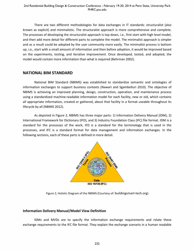
As depicted in Figure 2, NBIMS has three major parts: 1) Information Delivery Manual (IDM), 2)
International Framework for Dictionary (IFD), and 3) Industry Foundation Class (IFC) file format. IDM is a
standard for the processes of the work, IFD is a standard for the terminology that is used in the
processes, and IFC is a standard format for data management and information exchanges. In the
following sections, each of these parts is defined in more detail.
Figure 2, Holistic Diagram of the NBIMS (Courtesy of: buildingsmart-tech.org)
Information Delivery Manual/Model View Definition
IDMs and MVDs are to specify the information exchange requirements and relate these
exchange requirements to the IFC file format. They explain the exchange scenario in a human readable
2nd Residential Building Design & Construction Conference - February 19-20, 2014 at Penn State, University Park PHRC.psu.edu
232

format, as well as in a computer interpretable way for software vendors to implement the standard
(NBIMS 2012).
An IDM involves identification and documentation of information exchange processes and
requirements. These documents are typically expressed in human-readable form (Nawari and
Sgambelluri 2010). IDM supports the integrated construction processes by serving the technical
implementation needs of the software vendors and provides role—based process workflow for the end
user (Laasco & Kiviniemi 2012). IDM is an integrated reference for processes and data required by BIM
and specifies where a process fits; why it is relevant; who creates, consumes, and benefits from the
information; what is the information; and how should the software solution support this information
(Wix 2007; Laasco & Kiviniemi 2012).
An MVD is conceptually the process that integrates Exchange Requirements (ER) coming from
one or many IDM processes to the most logical Model Views that will be supported by software
applications. Implementation of these components will specify structure and format for data to be
exchanged using a specific version of the IFC file format. In other words, it standardizes the way that the
information for a certain Model View has to be organized, and then helps to show how the information
has to be digitally exchanged using the IFC file format (Nawari and Sgambelluri 2010, NBIMS 2012).
Industry Foundation Class
The IFC file format was developed by International Alliance for Interoperability (IAI) to address
the interoperability problems of BIM software. Now it is the standard format of the NBIMS. Using the
standard for information management and exchanges can guarantee the sustainable information
modeling in the project and prevent missing information during exchanges. IFC is a format for the
representation of the object, their attributes, relationships, and inheritance (Nawari and Sgambelluri
2010; Laakso and Kiviniemi 2012).
The IFC files take advantages of both structuralist and minimalistic approaches by using a
layered model (Tarandi 1998). As depicted in Figure 3, the structure of the IFC files is divided in four
layers, including domain, interoperability, core, and resource. The layers have a restrictive hierarchy and
the information in each layer has to be independent of the upper levels. The resource layer holds the
resource schema that contains basic definitions intended for describing objects in the higher layers. The
core layer consists of the Kernel and extension modules. The Kernel determines the model structure and
decomposition, providing basic concepts regarding objects, relationships, type definitions, attributes
and roles. Core extensions are specializations of classes defined in the Kernel. The interoperability layer
provides the interface for domain models, thus providing an exchange mechanism for enabling
interoperability across domains. The domain layer contains domain models for processes in specific AEC
domains or types of applications, such as architecture, structural engineering, and HVAC, among others
(IAI 1999a; IAI 1999b; IAI 2000, Laasco & Kiviniemi 2012).
2nd Residential Building Design & Construction Conference - February 19-20, 2014 at Penn State, University Park PHRC.psu.edu
233
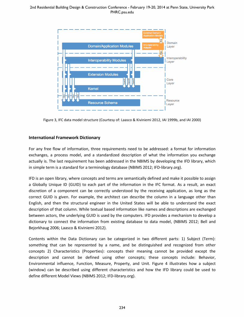
Figure 3, IFC data model structure (Courtesy of: Laasco & Kiviniemi 2012, IAI 1999b, and IAI 2000)
International Framework Dictionary
For any free flow of information, three requirements need to be addressed: a format for information
exchanges, a process model, and a standardized description of what the information you exchange
actually is. The last requirement has been addressed in the NBIMS by developing the IFD library, which
in simple term is a standard for a terminology database (NBIMS 2012; IFD-library.org).
IFD is an open library, where concepts and terms are semantically defined and make it possible to assign
a Globally Unique ID (GUID) to each part of the information in the IFC format. As a result, an exact
discretion of a component can be correctly understood by the receiving application, as long as the
correct GUID is given. For example, the architect can describe the column in a language other than
English, and then the structural engineer in the United States will be able to understand the exact
description of that column. While textual based information like names and descriptions are exchanged
between actors, the underlying GUID is used by the computers. IFD provides a mechanism to develop a
dictionary to connect the information from existing database to data model, (NBIMS 2012; Bell and
Bejorkhaug 2006; Laasco & Kiviniemi 2012).
Contents within the Data Dictionary can be categorized in two different parts: 1) Subject (Term):
something that can be represented by a name, and be distinguished and recognized from other
concepts 2) Characteristics (Properties): concepts their meaning cannot be provided except the
description and cannot be defined using other concepts; these concepts include: Behavior,
Environmental influence, Function, Measure, Property, and Unit. Figure 4 illustrates how a subject
(window) can be described using different characteristics and how the IFD library could be used to
define different Model Views (NBIMS 2012; IFD-library.org).
2nd Residential Building Design & Construction Conference - February 19-20, 2014 at Penn State, University Park PHRC.psu.edu
234

Figure 4, IFD application in BIM models (Courtesy of: IFD-Library.org and Lars Bjørkhaug-Catenda AS)
NBIMS EXTENSION PROCESSES
The NBIMS along with its open standard file format (IFC) is extendable for information modeling
and exchanges of any type of construction. For this extension, there are three steps that need to be
followed. In the following, these steps are explained.
Developing the Information Delivery Manual (IDM) is the first step. IDM is the user-interfacing
phase of NBIMS exchange standard development. First, a lifecycle process map of the BIM model has to
be defined. In this step the disciplines that are using the BIM model will be recognized. Then the
information exchanges between these disciplines at different phases of the work will be identified. Each
of these information packages that are being exchanged is one Exchange Model (EM) (Eastman et al.
2010). Examples of process map and EM definitions are depicted in Figure 5 and Figure 6, respectively,
which are developed for precast/prestressed concrete construction (Aram et al. 2010;
buildingSMARTAlliance 2011; Venugopal et al. 2012; Panushev et al. 2010).
Afterwards, the Exchange Models would be described. The information included in each of the
EMs has to be recognized and defined clearly. The specification of the required information in each of
Exchange Models is called Exchange Requirement (ER). An example of EM specification is depicted in
Figure 7 (Panushev et al. 2010). The set of the process maps and described EMs is called Information
Delivery Manual (IDM).
2nd Residential Building Design & Construction Conference - February 19-20, 2014 at Penn State, University Park PHRC.psu.edu
235

Figure 5: An example of process map (Courtesy of: Panushev et al. 2010)
Figure 6: An example of EM (Courtesy of Aram et al. 2010)
Figure 7: An example for EM specification (Courtesy of: Panushev et al. 2010)
2nd Residential Building Design & Construction Conference - February 19-20, 2014 at Penn State, University Park PHRC.psu.edu
236
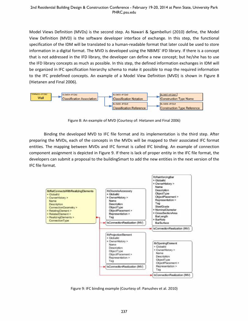
Model Views Definition (MVDs) is the second step. As Nawari & Sgambelluri (2010) define, the Model
View Definition (MVD) is the software developer interface of exchange. In this step, the functional
specification of the IDM will be translated to a human-readable format that later could be used to store
information in a digital format. The MVD is developed using the NBIMS’ IFD library. If there is a concept
that is not addressed in the IFD library, the developer can define a new concept; but he/she has to use
the IFD library concepts as much as possible. In this step, the defined information exchanges in IDM will
be organized in IFC specification hierarchy schema to make it possible to map the required information
to the IFC predefined concepts. An example of a Model View Definition (MVD) is shown in Figure 8
(Hietanen and Final 2006).
Figure 8: An example of MVD (Courtesy of: Hietanen and Final 2006)
Binding the developed MVD to IFC file format and its implementation is the third step. After
preparing the MVDs, each of the concepts in the MVDs will be mapped to their associated IFC format
entities. The mapping between MVDs and IFC format is called IFC binding. An example of connection
component assignment is depicted in Figure 9. If there is lack of proper entity in the IFC file format, the
developers can submit a proposal to the buildingSmart to add the new entities in the next version of the
IFC file format.
Figure 9: IFC binding example (Courtesy of: Panushev et al. 2010)
2nd Residential Building Design & Construction Conference - February 19-20, 2014 at Penn State, University Park PHRC.psu.edu
237
The whole developed documents including IDM, MVDs, and IFC bindings have to be sent to
NBIMS as a proposal for evaluation. Once accepted, it will be added to the standard and the software
vendors would have to adopt and implement the developed MVDs, concepts and entities to be qualified
for the buildingSmart IFC certificate. Accomplishing these activities will address the interoperability
problem in the area to which we are extending the NBIMS.
MAJOR EFFORTS RELATED TO STRUCTURAL ASPECTS
Many efforts have been done so far to extend the NBIMS to address interoperability issues in
different areas. Since software developers are responsible for practical implementations of the
standard, the Building Lifecycle Interoperable Software (BLIS) Group was founded in 1999 to fill the gap
between publication of the standard and its implementation in software. In 2006, BLIS introduced MVDs
as an official element for IFC standardization to show how data exchanges are applied between different
types of applications; and by this means benefits the implementers of IFC software (Laasco & Kiviniemi
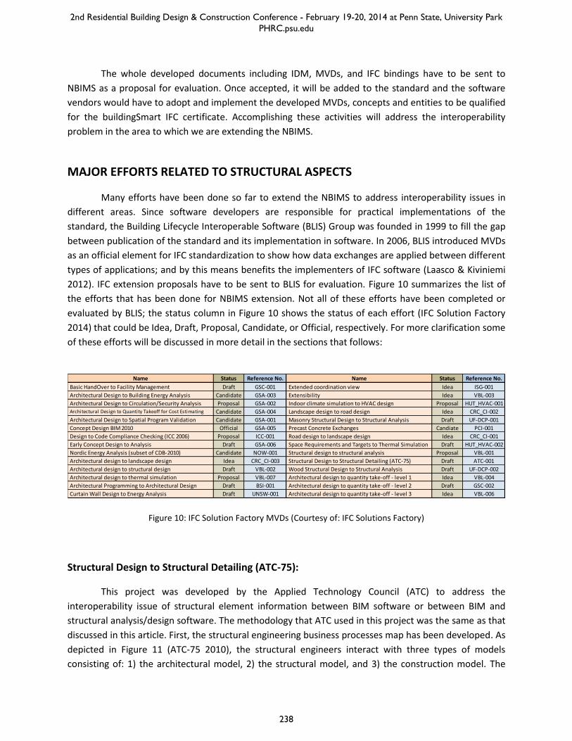
2012). IFC extension proposals have to be sent to BLIS for evaluation. Figure 10 summarizes the list of
the efforts that has been done for NBIMS extension. Not all of these efforts have been completed or
evaluated by BLIS; the status column in Figure 10 shows the status of each effort (IFC Solution Factory
2014) that could be Idea, Draft, Proposal, Candidate, or Official, respectively. For more clarification some
of these efforts will be discussed in more detail in the sections that follows:
Figure 10: IFC Solution Factory MVDs (Courtesy of: IFC Solutions Factory)
Structural Design to Structural Detailing (ATC-75):
This project was developed by the Applied Technology Council (ATC) to address the
interoperability issue of structural element information between BIM software or between BIM and
structural analysis/design software. The methodology that ATC used in this project was the same as that
discussed in this article. First, the structural engineering business processes map has been developed. As
depicted in Figure 11 (ATC-75 2010), the structural engineers interact with three types of models
consisting of: 1) the architectural model, 2) the structural model, and 3) the construction model. The
Name Status Reference No. Name Status Reference No.
Basic HandOver to Facility Management Draft GSC-001 Extended coordination view Idea ISG-001
Architectural Design to Building Energy Analysis Candidate GSA-003 Extensibility Idea VBL-003
Architectural Design to Circulation/Security Analysis Proposal GSA-002 Indoor climate simulation to HVAC design Proposal HUT_HVAC-001
Architectural Design to Quantity Takeoff for Cost Estimating Candidate GSA-004 Landscape design to road design Idea CRC_CI-002
Architectural Design to Spatial Program Validation Candidate GSA-001 Masonry Structural Design to Structural Analysis Draft UF-DCP-001
Concept Design BIM 2010 Official GSA-005 Precast Concrete Exchanges Candiate PCI-001
Design to Code Compliance Checking (ICC 2006) Proposal ICC-001 Road design to landscape design Idea CRC_CI-001
Early Concept Design to Analysis Draft GSA-006 Space Requirements and Targets to Thermal Simulation Draft HUT_HVAC-002
Nordic Energy Analysis (subset of CDB-2010) Candidate NOW-001 Structural design to structural analysis Proposal VBL-001
Architectural design to landscape design Idea CRC_CI-003 Structural Design to Structural Detailing (ATC-75) Draft ATC-001
Architectural design to structural design Draft VBL-002 Wood Structural Design to Structural Analysis Draft UF-DCP-002
Architectural design to thermal simulation Proposal VBL-007 Architectural design to quantity take-off - level 1 Idea VBL-004
Architectural Programming to Architectural Design Draft BSI-001 Architectural design to quantity take-off - level 2 Draft GSC-002
Curtain Wall Design to Energy Analysis Draft UNSW-001 Architectural design to quantity take-off - level 3 Idea VBL-006
2nd Residential Building Design & Construction Conference - February 19-20, 2014 at Penn State, University Park PHRC.psu.edu
238

whole processes of the structural design have been divided in four stages consisting of: 1) defining the
structural systems, 2) development of the structural model, 3) performing structural analyses for
verification, and 4) extracting structural drawings and specifications. Next, the Exchange Requirements
(ER) were recognized and based on that, the MVD has been developed and bound to the IFC format
(ATC-75 2010).
Figure 11: Structural engineering business processes map (Courtesy of: ATC-75 2010)
In this project, a benchmarking test has been done on a variety of BIM and structural design
software types to systematically quantify the state of interoperability in a methodical and
comprehensive format. This was also done to rate the success of information transfer from one software
to another. The criteria for these tests included the following: 1) the accuracy of geometric coordinate
transfer, 2) material properties transfer, 3) curved and shaped geometric transfer, and 4) sloped
geometric transfer. An identical simple model has been developed for the benchmarking tests. One
benchmarking test has been done before developing the IDM, MVD, and IFC binding and one done after.
The software vendors modified their software based on feedbacks from the project and the first
benchmarking test. The comparison of two benchmarking tests showed a significant improvement in the
correct information exchanges among these software. For more clarification, the result of the second
benchmarking test on Bentley Structural v8 is shown in Figure 12 (ATC-75 2010).
2nd Residential Building Design & Construction Conference - February 19-20, 2014 at Penn State, University Park PHRC.psu.edu
239

Figure 12: Second benchmarking test on Bentley Structural v8 (Courtesy of: ATC-75 2010)
Precast/Prestressed Concrete Constructions
This research was done to address the interoperability issues in the precast/prestressed
concrete industry. This research also followed the same methodology as discussed previously. First, the
IDM was developed for the planning, design, documentation, construction and fabrication phases and
their information exchanges (Panushev et al. 2010). Next, five different Model Views were defined and
bound to the IFC file format. These five MVDs are supporting the following five use cases:
Clash detection among different disciplines like MEP, structural or electrical -- In this model
view, the boundaries of the elements are important.
Structural analysis and design purposes -- This model view is in the form of nodes and axes and
3D geometry is not addressed, but the loads and the weight of the elements are concerned.
Precast fabrication purposes -- In this model view, the boundaries of the precast parts and the
hollow cores are addressed.
Parent assembly representation -- This is developed for the times that is needed to specify the
components that the parent assembly is composed of. In this model view, the geometry of the
parent assembly is derived from the geometry of individual components
Production and delivery sequencing -- Geometry is not concerned in this model view, but items
like piece counting and erection sequencing is important.
2nd Residential Building Design & Construction Conference - February 19-20, 2014 at Penn State, University Park PHRC.psu.edu
240

STANDARDIZATION IN MODULAR BUILDING CONSTRUCTION
Proper information exchange and integration of different project phases are the two
fundamental needs of the construction industry. Modular building industry is still at relatively early
stages of its development, therefore there is no specific code or standard for the modules and the
processes of this this type of construction; as a result, integration level of the information in this
industry is relatively low (McGraw-Hill 2011). Standardization of information exchanges can significantly
increase the information integrity level of the projects in this industry. In the following, the steps that
need to be followed to achieve this goal are summarized:
Product Architecture Model (PAM) development: There are many different innovative systems in
the modular industry and for developing a standard, these different systems have to recognized,
categorized, and documented. In the PAM, different options for the assemblies and subassemblies have
to be recognized based on the conventional modular systems; and then aspects such as functionality,
aesthetic, geometry, energy efficiency, and sustainability have to be mapped to these options; then,
attributes like scopes, limitations, and relations needs to be assigned to the assemblies and
subassemblies to come up with the Product Architecture Model.
IDM/MVD development: The processes of the modular building projects are different from the
site-built constructions; for example, modular building projects have two additional stages that are
manufacturing and transportation. In addition, the design considerations of modular buildings are
different as well. Therefore, a special process map along with exchange requirements required to be
developed to standardize the information exchanges in this industry. Furthermore, different MVDs need
to be defined to ease using the BIM model for different disciplines like structural engineer, architect,
manufacturer, logistic manager, etc.
Updating the IFD: Modular buildings contain a lot of assemblies and subassemblies. Each of
these assemblies is a concept. A lot of these concepts are new and are not addressed in the concepts
developed for site-built constructions (especially assemblies at higher levels); these concepts have to be
defined clearly to prevent any confusion. For example, it should be clear what subassemblies are
pointed out when we say the module’s light gage steel wall; does it mean the wall including the corner
posts of the module; does it mean the wall including the sheathing on the walls. Clear definition of the
new concepts will significantly increase the interoperability in this industry.
IFC Binding of the developed MVDs: In order to ease information exchanges between different
disciplines and make auto model view generations possible, the developed MVDs needs to be bound to
the IFC file. Since there are new concepts defined for the modular assemblies and subassemblies in the
IFD, new classes in the IFC file format need to be developed for storing new concepts’ information in the
IFC file. For example, if the structural engineer needs the equivalent stiffness and resistance of the walls
of modules, an entity needs to be defined in the IFC class of the module’s wall concept to store the
values of these parameters.
2nd Residential Building Design & Construction Conference - February 19-20, 2014 at Penn State, University Park PHRC.psu.edu
241
SUMMARY AND CONCLUSION
In this article, the National BIM Standard (NBIMS) has been reviewed. NBIMS has been
established to address information exchange issues in AEC industry. It has three main parts including:
Information Delivery Manual (IDM)/Model View Definition (MVD), Industry Foundation Class, and
International Framework for Dictionary. IDM/MVD specifies the information exchange requirements and
model views; IFC is a file format for digital storing and information exchange purposes; and IFD is like a
dictionary for defining concepts from different disciplines into a universally understood language. Next,
the methodology for extending the NBIMS for a certain area of the AEC industry was discussed. This
extension has three main steps including IDM, MVD and IFC file format binding. Then, efforts and the
methodology for extending NBIMS in different construction areas were discussed. One of these efforts is
Applied Technology Council’s (ATC) research for addressing interoperability issues in structural design to
structural detailing processes. The other one is the research for extending NBIMS issue in
Precast/Prestressed Concrete Constructions. At last, the steps that this research is seeking to extend the
NBIMS for modular building industry are discussed. These steps are: Development of Product
Architecture Model (PAM), IDM/MVD development, Updating the IFD, and IFC Binding of the developed
MVDs.
NBIMS is still in its infancy. There are many different ongoing researches and projects that are
trying to extend it for different types of construction and their different disciplines; and still many more
efforts needs to be done. Regarding the framework of the NBIMS, it does not just address the
interoperability issues, but it also standardizes the information flow and the construction processes.
Standardization of information flow and processes defines the responsibility of different disciplines to
each other clearly; and this helps to prevent constant challenges of different disciplines for receiving
their required information in a proper format and roper time. It has to be noted that by improvement
of the technology, the processes may be changed or some new attributes be added to the product, so
the IDMs and MVDs has to be updated constantly for the upcoming changes based the feedbacks from
the industry.
On the other hand, the software vendors can play a very important role in practical
implementation of different aspects of the NBIMS; the software vendors provide tools for leveraging
NBIMS in the projects. So, they have to adopt and implement the extension of the NBIMS to make it
possible to use the NBIMS extensions in the projects. Therefore, their participation in the extension
projects can speed up the NBIMS evolution and its adoption in the industry; in addition, it will guarantee
the feasibility of the full implementation of the NBIMS extensions.
2nd Residential Building Design & Construction Conference - February 19-20, 2014 at Penn State, University Park PHRC.psu.edu
242

REFFERENCES
Aram, S., Eastman, C. M., Sacks, R., Panushev, I., and Venugopal, M. (2010). Introducing a new
methodology to develop the information delivery manual for AEC projects. Proceedings of the CIB
W78 2010: 27th International Conference–Cairo, Egypt, Vol. 49.
Behrman, W. (2002). Best practices for the development and use of XML data interchange
standards. Center for Integrated Facility Engineering Technical Report, Stanford University, Vol. 131,
pp. 27.
Bell, H., and Bjørkhaug, L. (2006). A buildingSMART ontology. Proceedings of the 2006 ECPPM
Conference, Valencia, Spain, pp. 185-190.
Bloor, M. and Owen, J. (1995). Product data exchange. UCL Press, London, pp. 262.
Vries, H. J. (2005). IT Standards Typology. In: Jakobs K. (Ed.) Advanced Topics in In- formation Technology
Standards and Standardization Research Volume 1, Hershey, PA, USA, Idea Group Publishing, pp. 11-
36.
buildingsmart-tech.org – Homepage. <http://www.buildingsmart-tech.org> (accessed January 2014).
buildingSMARTAlliance (2011). A council of the National Institute of Building Sciences, Develop and
promote the National BIM Standard-United States™ and United States National CAD Standard,
<www.buildingsmartalliance.org> (accessed January 2011).
Eastman, C. (2012). The evolution of AEC interoperability. unpublished manuscript.
Eastman, C.M., Jeong, Y.-S., Sacks, R., and Kaner, I (2010). Exchange Model and Exchange Object
Concepts for Implementation of National BIM Standards. ASCE Journal of Computing in Civil
Engineering, 24(1), pp. 25-34.
Gielingh, W. (2008). An assessment of the current state of product data technologies. Computer Aided
Design. Vol. 40 (7), pp. 750-759.
Hietanen, J., and Final, S. (2006). IFC model view definition format. International Alliance for
Interoperability.
IFC Solutions Factory – The Model View Definition site. <http://www.blis-project.org/IAI-MVD/>
(accessed January 2014).
IFD-Library.org. IFD Library White Paper <http://www.ifd-
library.org/images/IFD_Library_White_Paper_2008-04-10_I_.pdf> (accessed January 2014).
IAI, (1999a). Specification Development Guide. Ed. Wix J and See R. International Alliance Of
Interoperability (IAI). Specification Task Force, pp. 47.
2nd Residential Building Design & Construction Conference - February 19-20, 2014 at Penn State, University Park PHRC.psu.edu
243
IAI, (1999b). IFC Object Model Architechture Guide. Ed. Liebich T and See R. International Alliance Of
Interoperability (IAI). Specification Task Force, pp. 9.
IAI, (2000). IFC Technical Guide - Enabling Interoperability in the AEC/FM Industry. Ed. Liebich T and Wix
J. Modeling Support Group. International Alliance Of Interoperability (IAI), pp. 46
Laakso, M., & Kiviniemi, A. O. (2012). The IFC standard: a review of History, development, and
standardization, Information Technology. ITcon, 17(9), 134-161.
McGraw-Hill Construction. (2011). Prefabrication and Modularization: Increasing Productivity in the
Construction Industry. Smart Market Report, McGraw-Hill Construction, New York, NY, USA.
National Institute of Building Sciences (NIBS), (2012). United States National Building Information
Modeling Standard: Version 2, buildingSMARTAlliance, <http://www.nationalbimstandard.org/>
(accessed January 2014).
Nawari, N. O., and Sgambelluri, M. (2010, May). The role of national BIM standard in structural design.
The 2010 Structures Congress joint with the North American Steel Construction Conference in
Orlando, Florida, pp. 1660-1671.
Panushev, I., Eastman, C. M., Sacks, R., Venugopal, M., and Aram, S. (2010). Development of the
National BIM Standard (NBIMS) for Precast/Prestressed Concrete. In Proceedings of the CIB W78
2010: 27th International Conference–Cairo, Egypt, Vol. 18.
Tarandi, V. (1998). Neutral Intelligent CAD Communication - Information exchange in construction based
upon a minimal schema, Doctoral Dissertation, Kungliga Tekniska Högskolan, Stockholm, pp. 194.
Venugopal, M., Eastman, C. M., and Sacks, R. (2012). Configurable Model Exchanges for the Precast/Pre-
stressed Concrete Industry using Semantic Exchange Modules (SEM). ASCE Journal of Computing in
Civil Engineering, pp. 269-276.
Wix, J., and Karlshoej, J. (2010). Information Delivery Manual: Guide to Components and Development
Methods. BuildingSMART International,
<http://iug.buildingsmart.org/idms/development/IDMC_004_1_2.pdf> (accessed January 2014).
2nd Residential Building Design & Construction Conference - February 19-20, 2014 at Penn State, University Park PHRC.psu.edu
244