integrated data capture, bim, cim, gis, and · pdf fileintegrated data capture, bim, cim,...
TRANSCRIPT

US Army Corps of Engineers
BUILDING STRONG®
Integrated Data Capture, BIM, CIM, GIS, and CAD- Owner and Industry Perspectives on Products, Processes
and Policies for Informed Decision Making
Steve HutsellChief, Geospatial Section USACE, Seattle District
Lou BushDirector of SurveyBowman Consulting Group
SPAR 3D Expo and Conference13 Apr 2016

Introductions Steve Hutsell
► Chief of the Geospatial Section for the U.S. Army Corps of Engineers (USACE), Seattle District, which supports local, regional and national BIM, Survey & Mapping, Civil Information Modeling (CIM), GIS, CAD and ProjectWise requirements and initiatives, collectively known as Advanced Integrated Modeling (AIM).
► Over 20 years of experience with AEC and Geospatial technology implementation and support at the USACE Fort Worth, Europe and Seattle districts, and at regional military installations.
► As a member of the Corps' BIM/CAD Community of Practice, Steve is honored to lead the USACE/Industry BIM & CIM Consortia in a partnered development of AIM Contract Requirements for civil and military projects.
► Earned his Bachelor of Science degree in Architectural Engineering from The University of Texas at Austin in 1985.

Introductions Lou Bush
► Director of Survey with Bowman Consulting Group.
► Licensed Professional Surveyor and Mapper with over 35 years of experience in photogrammetric mapping and surveying, LiDARmapping (both airborne and terrestrial), subsurface utility engineering (SUE), conventional land surveying, building information modeling (BIM), civil information modeling (CIM), 3D modeling and LiDARtechnology.
► Worked on projects across the Continental U.S., as well as in South America, in both the governmental and private sectors.
► Industry expert member of the USACE/Industry BIM & CIM Consortia, the National Institute of Building Sciences - buildingSMART Alliance, the U.S. Institute of Building Documentation (USIBD), and TRB AFB80 ‘Geospatial Data Acquisition Technologies in Design and Construction’.
Goal: Informed Decision Making
►Use data with a high level of reliability and integrity
• Trusted
• Current
• Accurate
• Comprehensive
• Timely
►Integrate relevant datasources
►Apply Products, Processes and Policies for increased data quality
Data Wrangler:Open Geospatial Consortium (OGC)
OGC excels at data integrity and integration structure
Over 519 international companies, government agencies and universities
OGC® Standards support interoperable solutions that "geo-enable" the Web, wireless and location-based services and mainstream IT.
Empower technology developers to make complex spatial information and services accessible and useful with all kinds of applications.

IFC
Space
Natural Asset
Linear Structure
Structure
Building
Facility / Built
Theatre / World
Sub-SystemsSystem
Level
Site
Real
Property Asset
Country
State / Province
County
Installation /
Region
Node
Segment
Room
Space
System
Level
Sub-Systems
Room
Water / Sea
Land / Parcel
Underground
Air / Space
Overlay
Overlay
Components
Components
City
The Open Geospatial Consortium (OGC)


Geographic Information System
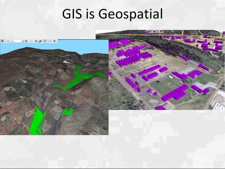
GIS is Geospatial

Isn’t Geospatial content just about GIS and mapping?
NO!

CIM Is Geospatial
Civil Information Modeling (CIM)
►Site/Infrastructure Design and Construction
►Surface and Subsurface Utilities and Features
►Survey/LIDAR/DTM
►Landscape Architecture

Civil Information
(CIM)

CIM – Similar to BIM, CIM is a 3-dimensionalfully attributed digital representation ofnatural features, man-made features, andfunctional characteristics of a project site.
Featured in the 2012 SmartMarket Report ‘The Business Value of BIM for Infrastructure’
►Referred to as ‘BIM for Civil Works’
What is Civil Information Modeling?
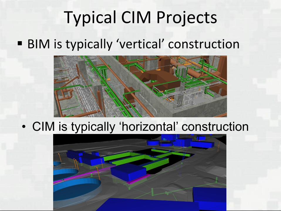
Typical CIM Projects
BIM is typically ‘vertical’ construction
• CIM is typically ‘horizontal’ construction

Sample Civil Works Projects
USACE Rock Island District developed additional
lock chamber to Lock and Dam #22

CIM Initiatives Government
►USACE• Military Construction (MILCON) and Civil Works
►Federal Agencies• FHWA, ASHTO?
►State Agencies• Oregon, Minnesota, Florida, etc.
►Local Agencies• Los Angeles CCD• City of Las Vegas, NV
Private-sector

Civil Information
(CIM)

Building Information Modeling
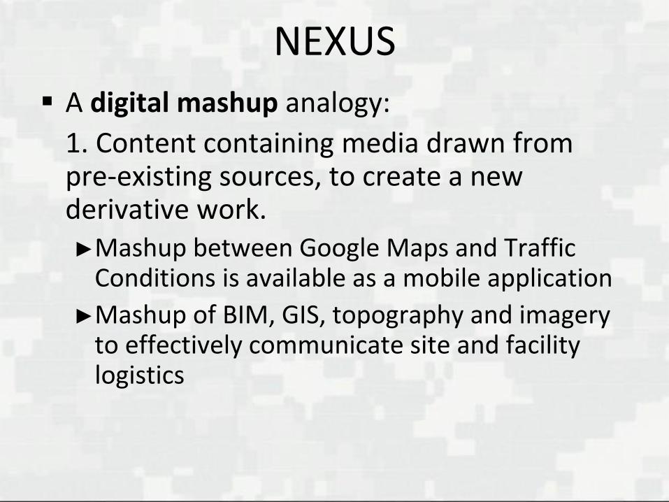
NEXUS
A digital mashup analogy:
1. Content containing media drawn from pre-existing sources, to create a new derivative work.►Mashup between Google Maps and Traffic
Conditions is available as a mobile application
►Mashup of BIM, GIS, topography and imagery to effectively communicate site and facility logistics
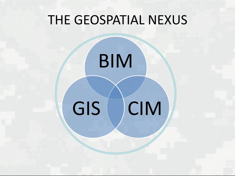
THE GEOSPATIAL NEXUS
BIM
CIMGIS

GIS
CIM BIM
MILCON Nexus Example

3D GIS campus map (showing extruded floor plates)
3D GIS campus map detail (showing extruded rooms)
COBie, BIM, GIS and other digital adventuresat the University of Washington
UW BIM/CAD/GIS System

AVATAR – FULL GEOSPATIAL NEXUS
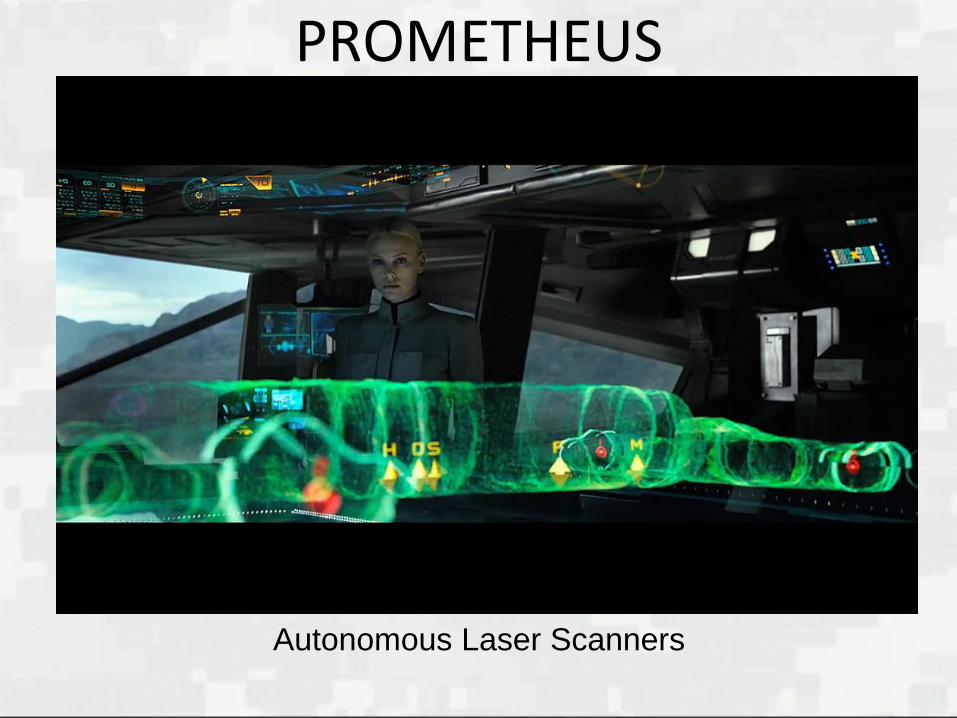
PROMETHEUS
Autonomous Laser Scanners

Geospatial Nexus
Challenges to a successful Nexus
Establishing the ‘single source of truth’
►Can the datasources be trusted?
• Is there missing or erroneous data?
►Are the datasources current?
• They must reflect current conditions.
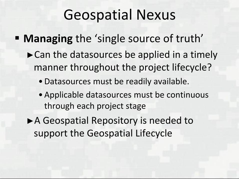
Geospatial Nexus
Managing the ‘single source of truth’
►Can the datasources be applied in a timely manner throughout the project lifecycle?
• Datasources must be readily available.
• Applicable datasources must be continuous through each project stage
►A Geospatial Repository is needed to support the Geospatial Lifecycle

Informed Decision Making
How does one acquire that knowledge via data integrity and integration?
►Standards
►Products
►Processes
►Policies

USACE Products, Processes and Policies
CAD Standards
BIM Standards
BIM Roadmaps
Engineering Regulations and Manuals
Engineering and Construction Bulletins
Contract Requirements
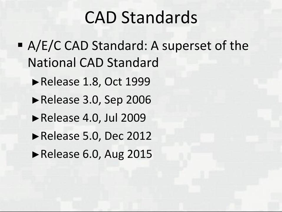
CAD Standards
A/E/C CAD Standard: A superset of the National CAD Standard
►Release 1.8, Oct 1999
►Release 3.0, Sep 2006
►Release 4.0, Jul 2009
►Release 5.0, Dec 2012
►Release 6.0, Aug 2015

CAD Standards
CAD Details Library
►ERDC/ITL TR-04-1, Jul 2004
►Revised Sep 2009
CAD Drafting Standard
►ERDC/ITL TR-12-1, Release 1.0, Jun 2012
A/E/C Graphics Standard
►ERDC/ITL TR-12-1, Release 2.0, Aug 2015

National BIM Standard Best Practice
USACE BIM Contract Requirements included as a ‘Best Practice’ Item for National BIM Standard-US, Version 3.
‘Practical BIM Contract Requirements’
► A successful example for agencies and owners wishing to implement BIM

Geospatial Regulations
Engineer Regulation
►ER 1110-1-8156, Engineering and Design: Policies, Guidance, and Requirements for Geospatial Data and Systems, Sep 2012
Engineering Manual
►EM 1110-1-2909, Engineering and Design: Geospatial Data and Systems, Sep 2012
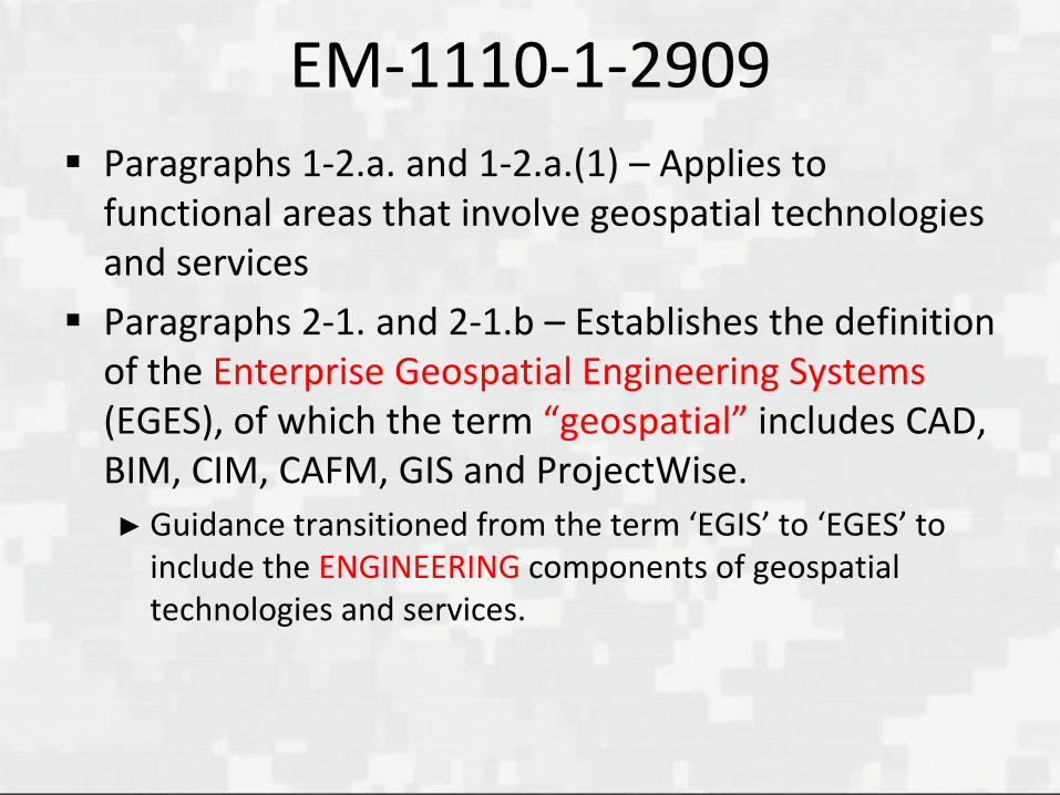
EM-1110-1-2909
Paragraphs 1-2.a. and 1-2.a.(1) – Applies to functional areas that involve geospatial technologies and services
Paragraphs 2-1. and 2-1.b – Establishes the definition of the Enterprise Geospatial Engineering Systems (EGES), of which the term “geospatial” includes CAD, BIM, CIM, CAFM, GIS and ProjectWise.
► Guidance transitioned from the term ‘EGIS’ to ‘EGES’ to include the ENGINEERING components of geospatial technologies and services.

EM-1110-1-2909
2-1.b - The term “geospatial” includes data, tools, technologies, and services used in the following fields:
Building Information Modeling (BIM)
Civil Information Modeling (CIM)
Computer-Aided Design (CAD)
Computer-Aided Facilities Management (CAFM)
Geographic Information Systems (GIS)
Global Positioning System (GPS)
Remote Sensing
Survey and Mapping

Engineering and Construction Bulletins
ECBs expire after two years
ECB 2006-15: Standardizing CAD and GIS Deliverables for all Military Design and Construction Projects
ECB 2012-22: Standardization of CAD, BIM and GIS Deliverables for Military Design and Construction Projects

Engineering and Construction Bulletins
►ECB 2013-18: BIM Requirements on USACE Projects
• All Army vertical construction projects, regardless of funding source, shall utilize BIM in accomplishing their design and construction.
• All other vertical construction projects, regardless of funding source, shall utilize BIM unless directed by the customer with a valid justification.

Engineering and Construction Bulletins
• All Civil Works horizontal construction projects shall use BIM or related Civil Information Modeling (CIM) tools (such as Autodesk Civil 3D, Bentley Systems InRoads, or other appropriate civil design tools) in accomplishing design and construction.

ECB 2016-3: Advanced Modeling Requirements
Applies to all USACE Commands with a mission to support Military Construction (MILCON); Sustainment, Restoration, and Modernization (SRM); and Civil Works projects.
Project requirements thresholds
► MILCON/SRM: $2.5M & 5000 Gross SqFt
►Civil Works: $2.5M
www.wbdg.org/ccb/browse_cat.php?c=268

USACE Advanced Modeling Requirements
1. Contract Language
2. Project Execution Plan (PxP) Template
3. Minimum Modeling Matrix (M3)
In development
► Submittal Review Checklist (CHX)
►CHX Guide

USACE Proven Results
500+ single- and multi-facility BIM projects executed since January 2008
►46 million-plus square feet
►$9 billion-plus in construction programming.
600+ facilities, 25 million-plus square feet, have been constructed to date.

Adopted by Others
Projects have been executed by other programs or agencies, such as
►U.S. Army MILCON Non-CoS projects
►Defense Health Agency
• MBR – Minimum BIM Requirements
►U.S. Air Force
►U.S. Navy - NAVFAC
►FAA
Contract Language
Why is this needed?
►If you don’t require ‘it’, you won’t get ‘it’.
►If you don’t check ‘it’, you won’t get ‘it’.

PxP Template
Why is this needed?
►Verify Contractor’s means and methods will meet the Advanced Modeling Contract Language requirements
►Part of QA/QC process
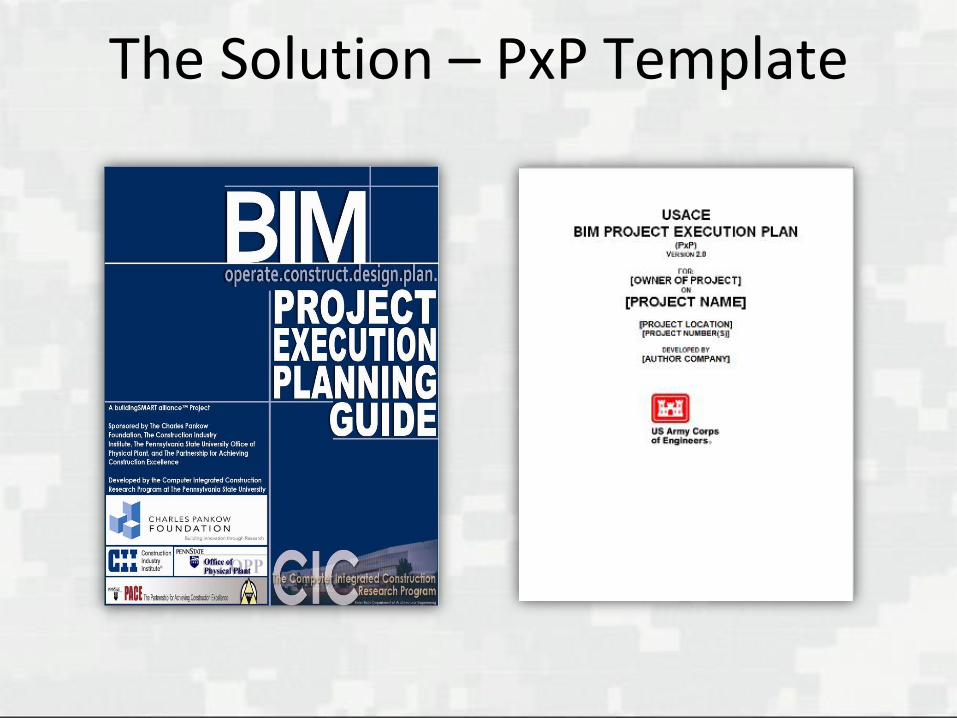
The Solution – PxP Template

Mandatory Model Uses• PxP Section C: Project Goals/
BIM Objectives
• Red & X’s are Required
• Contractor-elected BIM Uses
are highlighted in Yellow and
marked with a ‘C’

PxP Template
What are the benefits?
►Assists Governmental and Industry organizations in planning their BIM process
►Provides a standard format that streamlines the development of an Implementation Plan
►Review and acceptance process is accelerated

M3 Establishes Minimum Modeling requirements Why is this needed?
►Definitive establishment of Model ‘level of development’ and dimensional format ‘grade’
►Many Contractors were claiming exceptions or ‘waivers’ based on statements that the minimum modeling requirements specified in the Contract Language were ‘ambiguous’ or ‘open to interpretation’.
►A need for Modeled elements to be identified and defined via established classification system(s)
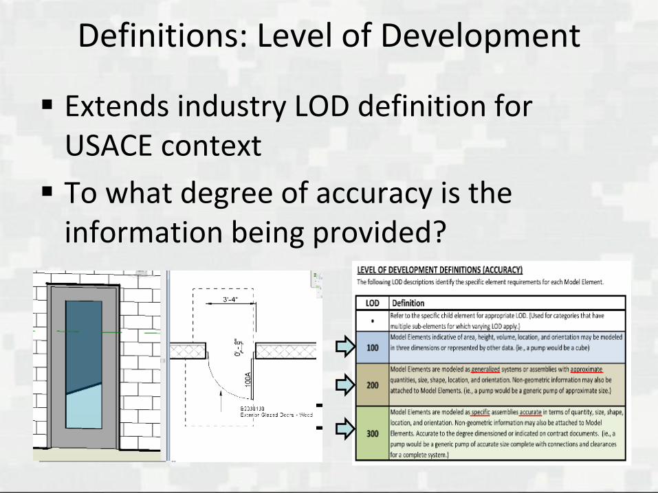
Definitions: Level of Development
Extends industry LOD definition for USACE context
To what degree of accuracy is the information being provided?

Definitions: Element Grade
• What format is the content
supposed to be delivered in?
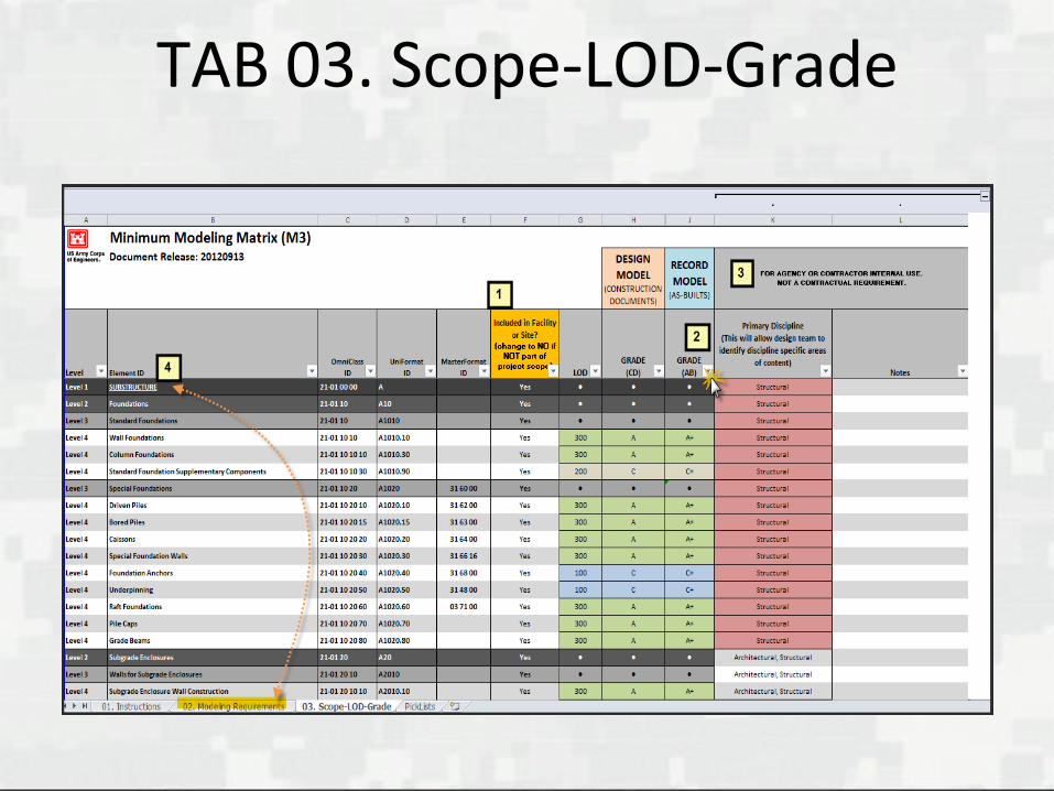
TAB 03. Scope-LOD-Grade

TME Article, Nov-Dec 2012
Boosting MILCON Performance
►Development, Purpose and Application of the USACE Minimum Modeling Matrix (M3)
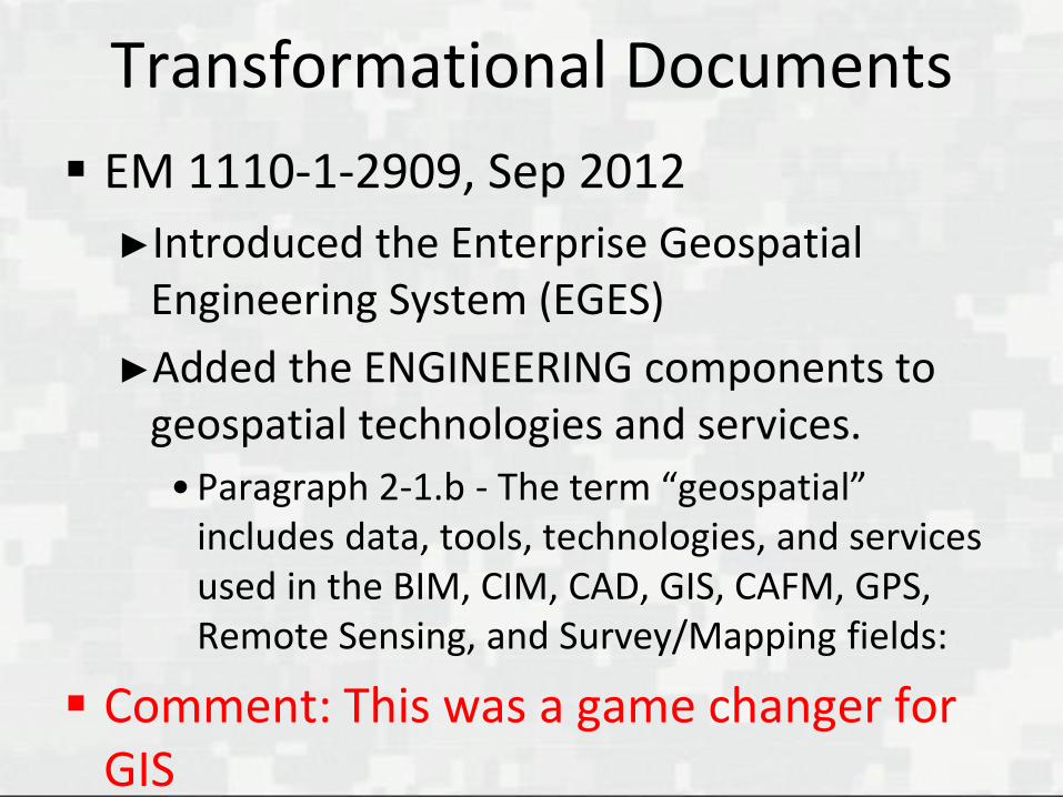
Transformational Documents
EM 1110-1-2909, Sep 2012
►Introduced the Enterprise Geospatial Engineering System (EGES)
►Added the ENGINEERING components to geospatial technologies and services.
• Paragraph 2-1.b - The term “geospatial” includes data, tools, technologies, and services used in the BIM, CIM, CAD, GIS, CAFM, GPS, Remote Sensing, and Survey/Mapping fields:
Comment: This was a game changer for GIS

Transformational Documents
ECB’s included CAD, BIM, CIM and GIS requirements
►ECB 2016-3, Covers BIM and CIM pieces of Advanced Modeling contract requirements of the soon to be released Specification Section 01 33 16.00 10.
• CAD and GIS requirements will be addressed in a near-future ECB, aligning with scope of the EM, and Section 01 33 16.00 10.

Transformational Documents
Specification Section 01 33 16.00 10
►Introduces the ‘Advanced Modeling’ definition and project context
• A subset of geospatial technologies as defined in EM 1110-1-2909 to include BIM, CIM, GIS, and CAD.
• Models and drawings that form a digital representation of the project, or part thereof, that are comprised of model elements with facility data.

USACE Contract Requirements
How were they developed?
►Collaboration with Industry

BIM Consortium Inception
In Fall of 2006, USACE established a dialog
with BIM-aggressive firms in conducting
discussions and workshops on mutually
beneficial BIM issues
►Collaboration provided a tremendous opportunity
to work together in strengthening federal and
private sector BIM initiatives.
►Best practices, Contract language, Standards
►CIM initiatives began in 2012

USACE/Industry BIM Consortium
Membership requirements
►Participation is strictly voluntary
►All costs incurred to participate are the responsibility of the firms/agencies
►Monthly on-site/webmeeting workshops and bi-weekly conference calls
►Minimum level of participation required to maintain active status

CIM Consortium Inception
Established in Summer of 2012
CIM-aggressive Survey and Design/
Construction firms in conducting
discussions and workshops on mutually
beneficial CIM issues
►Survey CIM and Site CIM Groups

Why was the CIM Consortium formed?
Apply same benefits to the site design and construction requirements realized in BIM.
►Create CIM standard processes and contract requirements
►Survey deliverables need to support 3D site design and construction processes and tools
• This has had limited consideration in the industry.

Why was the CIM Consortium formed?
Close the gap between BIM and GIS
Industry Innovation: MAP 21, LandXML, TransXML, InfraGML, IFC, CityXML

Survey CIM
3D Survey of Existing Conditions
AEC CIM
Civil/Site Design & Construction
AEC BIM forFacility Design & Construction
CIM Consortium
BIM and CIM Consortia Relationship
BIM Consortium
Mission of the Consortia
Push for innovation within an Advanced Modeling application-neutral context, yet ensure that the requirements are fair, practical and reasonable within the existing state of technology and standards.

NIBS Journal Article, Dec 2013
Win-Win BIM: How USACE and Industry Established Mutually Beneficial BIM Requirements

BIM/CIM Consortia Members
The U.S. Army Corps of Engineers does not endorse any of the firms/individuals referenced in or participating in this presentation.
Contract Requirement Benefits
Fair, Practical and Reasonable
Proven Results
Adopted by others
Mutually Beneficial for Owners and Industry
Benefits to Owners and Industry
Clarifies expectations
►Standard definition of deliverables
►Predictable consistency resulting in efficiencies and best value for the budget.
►Reduces conflict between AE and Contractor on expectations and responsibilities
Achievable with current technology and standards

Benefits to Owners and Industry
Applicable to Large and Small Firms
►‘8a’ Small Firms have been successful on USACE MILCON projects
• Directly related to quality of BIM Manager and level of support from management
Highlight
The USACE Advanced Modeling Contract Requirements are a proven and practical set of requirements, developed in collaboration with Industry, that serve as a valuable resource to government/ private-sector owners and contractors.
Can be downloaded @ CAD/BIM
Technology Centerhttps://cadbim.usace.army.mil/default.aspx?p=a&t=1&i=14
Other Developments
Facility Data Exchange
►A subset of COBie for USACE projects
• Policy, process, tools and pilots
►Attribution of assets supporting life-cycle processes
• Plan, Survey, Design, Build, Operation & Maintenance, Facilities Management, Renovation

Other Developments
Quantity Takeoff and Advanced Modeling integration
►Accurate quantities to feed USACE Cost Estimation software
• Best modeling practices
• All disciplines
Geospatial NexusThe consolidation of CAD, BIM, CIM and
GIS data sources…
The consumption, analysis, synthesis and delivery of the virtual and multi-dimensional representation of
Planned – Designed – Built – Managed environments
for Planning and Executing key physical and functional project characteristics prior to implementation
Provides for Informed Decision Making and Reduction in Risk!
BUILDING STRONG®
GAINED KNOWLEDGE
Ignorance is not lack of intelligence; it is lack of knowledge on a particular subject.
Virtualization and multi-dimensional representation reveal knowledge and that knowledge is power to:
►Plan and Execute key physical and functional project characteristics prior to implementation on planned, designed, built and managed environments.

Components of CIM
CIM is comprised of Survey CIM and Site CIM
– Survey CIM: Existing Conditions 3D Model
• 3D surface and subsurface geometric content of existing conditions developed by surveyors.
– Site CIM: Civil/Site 3D Model• Proposed 3D site or infra-
structure design developed by engineers.
Survey CIM
Site CIM
CIM

Survey CIM
Surface Features
•Entails the measurement, modeling and attribution of existing surface features captured by geomatic/survey processes, such as buildings, roads, utility poles, transformers, and fences.
•In addition, the model requires surface features not customarily included in a survey such as trees and overhead wires

Survey CIM
Subsurface Features
►Additional features such as foundations, abutments, piles, piers, tunnels, wells, tanks, abandoned-in-place man-made features, and natural geotechnical features (voids, outcroppings) are incorporated.

Survey CIM
Adequately verifying subsurface utility features requires meeting Subsurface Utility Engineering (SUE) criteria
What is Subsurface Utility Engineering?
SUE
►An engineering process that establishes a method of discovery and verification of subsurface utility systems.
• It utilizes geophysical technology such as Ground Penetrating Radar (GPR) and is guided by CI/ASCE 38-02, which establishes SUE Quality Levels A-D for defining the quality of utility location and the attribute information.

Seattle District Survey CIM

Courtesy of VTN Consulting
3D Infrastructure Model, Las Vegas

Survey CIM: Surveyor’s Objectives
Understanding Industry Standards
Defining Level of Development
Defining Level of Accuracy
► Absolute
► Relative
► Standard Deviation

The Role of Surveying in CIM
Baseline/Foundation
►Good Geospatial data is essential
Professional Oversite/Accountability
Reliable Data
• Trusted• Metadata
• Truth in Labeling
• Current/Legacy• Relevant to project
• Accurate• Relative
• Absolute
• Comprehensive• All inclusive
• Professional opinion
and report

Unique Survey CIM Challenges
Capturing, Creating and Utilizing 3D Content
►Modeling Challenges
• Compared to BIM, CIM has a less comprehensive software toolset
►Measurement of Non-Verifiable Survey CIM Content
• Adjust the M3 LOD for non-verifiable elements

Survey CIM Applications

Site CIM
CIM/BIM Models and Site/Building Data integrated for optimal coordination of facility Life-cycle project requirements.
►Entails Modeling and Facility Data for site and infrastructure design
►Within the construction limit and utility corridors extending to the nearest connection and subsurface utilities located 5' outside the building footprint.
Site CIM: Surveyor’s Objectives
Understanding the PxP and M3
Understanding Facility Data
Understanding the Deliverables
►Format
►Data Structure
Positions the Surveyor to be better equipped to collaborate on the project

Site CIM Applications Design Coordination / Constructability Review
Construction Scheduling
Quantity Take Off
GPS and Model Based
Machine Control► Trench Excavation, Site Grading
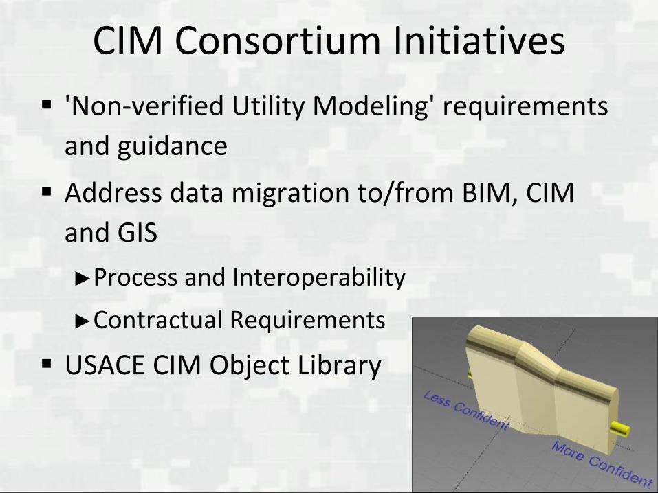
CIM Consortium Initiatives
'Non-verified Utility Modeling' requirements
and guidance
Address data migration to/from BIM, CIM
and GIS
►Process and Interoperability
►Contractual Requirements
USACE CIM Object Library
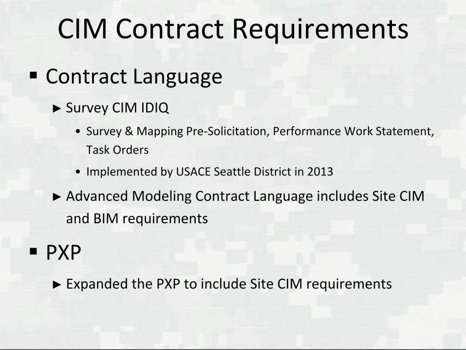
CIM Contract Requirements
Contract Language► Survey CIM IDIQ
• Survey & Mapping Pre-Solicitation, Performance Work Statement,
Task Orders
• Implemented by USACE Seattle District in 2013
► Advanced Modeling Contract Language includes Site CIM
and BIM requirements
PXP► Expanded the PXP to include Site CIM requirements

CIM Contract Requirements
Minimum Modeling Matrix (M3)► Expanded the M3 to include Minimum Modeling
Requirements for Existing Site Conditions
What’s In It For The Surveyor?
Greater Role in Project Development
Quicker Response and Interaction
Opportunity To Grow A New Definition Of ‘SURVEYOR’

Effects on the Survey Profession
Closer Professional Relationships:
►Architects
►Designers
►Constructors
Greater Interoperability/Coordination
►Workflow
►Lifecycle

Applying an Informed DecisionMaking and Risk Reduction Process Challenge: Projects suffer cost overruns
and time setbacks due to inadequatecoordination of project site designs and building designs or with existing surfaceand subsurface conditions.

Scenario On A Recent Project:
Inadequate coordination resulted in $1 Million in contract modifications
Required time extension for redesign and regrading
Caused significant project delays - 110 days lost
Incurred a 4% increase in project cost!
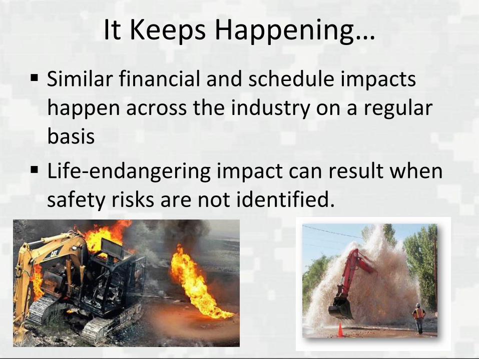
It Keeps Happening…
Similar financial and schedule impacts happen across the industry on a regular basis
Life-endangering impact can result when safety risks are not identified.

Infrastructure Can Be A Real Mess

What’s The Answer?
These issues can be addressed with an
innovative workflow for minimizing risks
through the proper integration of CIM
and BIM
What’s The Answer?
After all, BIM has been increasing
efficiencies and minimizing design and
construction coordination risk in building
projects for years in the AEC industry
Why not apply a similar process to the
equally important survey capture,
site/building design coordination, and
construction portions of a project?
Workflow For Minimizing Risks
Survey CIM and Site CIM Integration
►Combining the project Survey CIM Model with the proposed Site CIM Model provides a comprehensive project CIM MODEL.

What Can Be Done With a CIM Model?
Every project will encompass either building or site requirements or, most commonly, both. Fortunately, many ‘Model Uses’, defined in the National BIM Standard, can be adopted for CIM, such as:
• Design authoring
• Design reviews
• Interference management
(3D coordination)
• Construction scheduling (4D)
• Cost estimation (5D)
• Existing conditions modeling
• Record modeling

What Can Be Done With a CIM Model?
Additionally, CIM-specific uses in survey, site design, and construction, such as ‘Trench Construction Modeling’ are being employed.

CIM and BIM Integration
Integrating the Survey CIM, Site CIM, and BIM, along with their respective attribution, provides extremely valuable information for the designer, builder, and owner
Increases communication and collaboration

CIM and BIM Integration
Focused on maximizing project efficiency and coordination
Assists in the planning, design, construction, maintenance and operation of the built environment.
Supports Informed Decision Making and Risk Reduction

CIM and BIM Integration
Image courtesy of Sundt Construction, Inc.

CIM and BIM Integrated Work Process
The process includes two integration phases
►Survey and Site CIM Integration
►CIM and BIM Integration

Survey and Site CIM Integration
Starts with integrating the Surface/ Subsurface Survey 3D Model and the Civil/Site 3D Model
Minimizes the risk of conflicts with undiscovered or forgotten subsurface elements.

Survey and Site CIM Integration
Next, there’s a 3-Step Information Exchange
►Initial CIM Survey
►Preliminary Site CIM Design
►Risk Reduction SUE CIM Survey if needed

Survey and Site CIM Integration
Step 1 - Initial Survey CIM:
►Review existing record information
►Conduct typical field and aerial surveys, plus vertical measurement, for use in 3D modeling and attribution
►Use traditional utility-locate processes — to SUE Quality Level ‘C’ — to identify utility type and approximate horizontal position
Survey and Site CIM Integration
Step 1 continued
►Measure surface-accessible subsurface structures, such as invert elevations of pipes in manholes
►Use record information to supplement 3D modeling and attribution of field-surveyed subsurface features
Survey and Site CIM Integration
Step 2 - Preliminary Site CIM Design:
►Develop the Site CIM and Site Data to meet project delivery requirements
►With the Survey and Site CIMs, conduct multidisciplinary design reviews
►As a design team, identify potential conflicts between existing conditions and proposed subsurface utility and foundation designs
• this identifies locations where subsurface conditions need to be identified more accurately
Survey and Site CIM Integration
Step 3 - Risk Reduction SUE Survey CIM:
►Perform additional survey for subsurface utilities
• To SUE Quality Level ‘A’, the highest level of accuracy, which identifies type, size, condition, material, etc.
• Only in locations identified by the design team in Step 2
►Use the additional survey information to expand and enhance the Survey CIM as needed

Survey and Site CIM Integration
The distinction between the Initial Survey and any follow-on SUE Survey allows the process to be efficient as well as effective
►SUE Quality Level ‘A’ data can be expensive and time-consuming to capture and is generally not needed for the entire site, but only for locations that can be identified by the design team as described in Step 2.

Survey and Site CIM Integration
►This empowers the design team, allowing them to request SUE Quality Level ‘A’ data only at those locations deemed most critical.
►This results in more complete CIM development earlier in the design process than ever before, achieving the level of knowledge that effectively reduces risk but with less time and cost than required to survey the entire site to SUE Quality Level ‘A’.

CIM and BIM Integration
Much like the 3D coordination of building systems with BIM, the CIM and BIM models are integrated to maximize the collaboration and coordination of disciplines
►The fourth step in the Integrated Work Process effectively reduces project risk through the optimal coordination of common site and building systems and structures.

CIM and BIM Integration
Step 4 - Design and Construction Optimization:
►Allows site designers opportunity to visualize existing and proposed surface and subsurface features, to ensure design intent works in context with the building and site conditions
►Facilitates coordination with BIM during construction
►Supports designer decisions by allowing 3D analysis and cost impact in real time as the BIM and CIM are updated
CIM and BIM Integration
Application of the CIM and BIM Integration Work Process clearly shows how integrating survey, site, and building models (data and attribute rich) can optimize the coordination of a project.

NIBS Journal Article, Oct 2014
Bringing CIM to the Surface
www.journalofthenationalinstituteofbuildingsciences.com/2014/october/files/24.html

What’s Coming…
As ‘Information Sleuths’ of existing conditions, Surveyors and others have a role in the expansion of ‘Information Management’ initiatives and the waves of change in reality capture, modeling and attribution technology and processes.
Get involved by joining the USACE/ Industry CIM Consortium!

Improved Decision Making
Poor data quality and missed opportunities to coordinate systems and structures too often result in great cost to project owners. However, surveyors, designers, builders, and owners can use products, processes and policies for Informed Decision Making to better aid them in efficiently and cost-effectively predicting, preventing, and minimizing risk

Ultimate Mashup
AC/DC + Bagpipes + Flames = AWESOME!

BUILDING STRONG®
Contact Info
- Lou BushBowman Consulting Group
863-255-2308
- Steve HutsellUS Army Corps of Engineers
Seattle District
206-295-8246

BUILDING STRONG®
Credits Star Wars Episode IV: A New Hope
► Directed by George Lucas; Produced by Gary Kurtz; Released May 25, 1977
Avatar► Directed by James Cameron; Produced by James Cameron; Released
December 10, 2009
Prometheus► Directed by Ridley Scott; Produced by David Giler, Ridley Scott, Tony Scott,
Walter Hill; Released July, 2012