integrated manufacture of exoskeletons and sensing...
TRANSCRIPT

Duncan W. HaldaneDepartment of Mechanical Engineering,
University of California,
Berkeley, CA 94720
e-mail: [email protected]
Carlos S. CasarezDepartment of Mechanical Engineering,
University of California,
Berkeley, CA 94720
Jaakko T. KarrasRobotic Actuation and Sensing Group,
NASA Jet Propulsion Laboratory,
Pasadena, CA 91101
Jessica LeeDepartment of Mechanical Engineering,
University of California,
Berkeley, CA 94720
Chen LiDepartment of Electrical Engineering and
Department of Integrative Biology,
University of California,
Berkeley, CA 94720
Andrew O. PullinDepartment of Mechanical Engineering,
University of California,
Berkeley, CA 94720
Ethan W. SchalerDepartment of Electrical Engineering and
Computer Sciences,
University of California,
Berkeley, CA 94720
Dongwon YunDepartment of Electrical Engineering and
Computer Sciences,
University of California,
Berkeley, CA 94720
Hiroki OtaDepartment of Electrical Engineering and
Computer Sciences,
University of California,
Berkeley, CA 94720
Ali JaveyProfessor
Department of Electrical Engineering and
Computer Sciences,
University of California,
Berkeley, CA 94720
Ronald S. FearingProfessor
Department of Electrical Engineering and
Computer Sciences,
University of California,
Berkeley, CA 94720
e-mail: [email protected]
Integrated Manufactureof Exoskeletons and SensingStructures for Folded MillirobotsInspired by the exoskeletons of insects, we have developed a number of manufacturingmethods for the fabrication of structures for attachment, protection, and sensing. Thismanufacturing paradigm is based on infrared laser machining of lamina and the bondingof layered structures. The structures have been integrated with an inexpensive palm-sizedlegged robot, the VelociRoACH [Haldane et al., 2013, “Animal-Inspired Design and Aer-odynamic Stabilization of a Hexapedal Millirobot,” IEEE/RSJ International Conferenceon Robotics and Automation, Karlsruhe, Germany, May 6–10, pp. 3279–3286]. We alsopresent a methodology to design and fabricate folded robotic mechanisms, and havereleased an open-source robot, the OpenRoACH, as an example implementation of thesetechniques. We present new composite materials which enable the fabrication of stron-ger, larger scale smart composite microstructures (SCM) robots. We demonstrate howthermoforming can be used to manufacture protective structures resistant to water andcapable of withstanding terminal velocity falls. A simple way to manufacture tractionenhancing claws is demonstrated. An electronics layer can be incorporated into the robotstructure, enabling the integration of distributed sensing. We present fabrication methodsfor binary and analog force sensing arrays, as well as a carbon nanotube (CNT) basedstrain sensor which can be fabricated in place. The presented manufacturing methodstake advantage of low-cost, high accuracy two-dimensional fabrication processes whichwill enable low-cost mass production of robots integrated with mechanical linkages, anexoskeleton, and body and limb sensing. [DOI: 10.1115/1.4029495]
1 Introduction
An insect’s exoskeleton is an ideal model system for studyingintegrated structures in nature. It provides structural support,
Manuscript received August 16, 2014; final manuscript received December 23,2014; published online February 27, 2015. Assoc. Editor: Aaron M. Dollar.
Journal of Mechanisms and Robotics MAY 2015, Vol. 7 / 021011-1Copyright VC 2015 by ASME
Downloaded From: https://mechanismsrobotics.asmedigitalcollection.asme.org/ on 06/16/2015 Terms of Use: http://asme.org/terms

anchors actuators, is used for locomotion as well as sensing, andprovides protection for the animal. Many insects and arthropodshave integrated anisotropic spines which enable climbing andlocomotion on sparse terrain [1]. More recent research has foundthat shape and compliance of the exoskeleton plays a part inhigher level locomotory behavior. Discoid cockroaches use theirflexible streamlined bodies to easily traverse cluttered terrain [2].The integrated structures in the exoskeletons of insects enable sen-sory and perceptive behaviors. Robots with these same abilitieswill be more robust while operating in unknown environments.
In particular, we seek to enable these behaviors for palm-sizedrobots designed to operate in rough terrain, such as those shownin Fig. 1. Robots at this scale have several advantages over largerrobots. It is easier for humans or other robots to deploy them.They can access small crevices that would be inaccessible tolarger systems. Smaller systems can be inherently more robustthan larger ones [3], and materials which would be too weak orcompliant in a large robot are readily applicable at the smallersizes. The limitation of these smaller robots, however, is that theintegration of the type of sensing, protective, and locomotorystructures that are seen in nature cannot be accomplished with tra-ditional manufacturing methods. Novel and alternative manufac-turing methods advance the field toward integrating thesestructures into small robots.
1.1 Background. The SCM process was developed as a wayto fabricate mechanisms for microscale robots [4,5]. Traditionalmachine elements such as bushings or bearings do not scale downwell in size, and greatly increase cost with higher precision. TheSCM process replaces these components with flexural hinges thatapproximate revolute joints (see Fig. 2). SCM structures are pro-duced using planar laser cutting processes. The process was intro-duced with cardboard by Hoover and Fearing [6] and compositematerials in Wood et al. [7]. Its distinguishing feature is thatthe rigid links and flexible joints are cofabricated with layeredlaminar processes.
Although originally developed for microscale robots, recentwork has expanded SCM up to palm-size robots. These leggedrobots weigh between 15 and 30 g, and are capable of crawling[8], running [9–11], turning [12,13], and climbing [14,15]. Inte-grated kinematic linkages made with the SCM process drive theappendages of these robotic platforms. These linkages producethe desired kinematic output for all of the appendages using onlya few actuators which reduces the complexity of the system.
SCM has advantages which relate to the manufacturability ofrobots made with the process. Because SCM is a layered
approach, it is compatible with reel-to-reel manufacturing, givingthe designer good confidence that the SCM portion of the robotunder development is compatible with extant mass-manufacturingtechniques. When designing products for assembly, it is importantto reduce the number and diversity of parts and to make the partseasy to assemble [16]. Unlike traditional manufacturing methods,SCM parts which require relative kinematic motion can be readilycombined, thereby decreasing the overall part count. The entirekinematic structure of the robot is fabricated from only a fewmaterials. Therefore, the diversity of required components formaking a wide variety of robots is minimized, which is desirablefor high-mix manufacturing environments.
The layered nature of the SCM process allows specializedmaterials to be incorporated during the manufacture of roboticmechanisms. This inherent extensibility allows for the manufac-ture of more complex integrated structures than have previouslybeen explored. The next step for palm-sized robots is to use SCMto integrate protective and sensing structures that will allowextended field operation.
1.2 Paper Overview. This work focuses on manufacturingmethods for SCM mechanisms with integrated structures for sens-ing, protection, and attachment. In terms of paper organization,each subsystem has been compartmentalized into its own section.To facilitate the design of new robots made with SCM, we presentdesign guidelines in Sec. 2. A method to rapidly produce palm-sized SCM robots is given in Sec. 3. Suitable materials for SCMare discussed in Sec. 4. Thermoformed shells for aiding obstacletraversal and protecting SCM robots are presented in Sec. 5. Ani-sotropic claws for improving climbing performance are demon-strated in Sec. 6. Sensing structures are also integrated into thedesign of SCM robots. Ground obstacles and contact forces fromobstacles met head-on can be detected using binary hair sensorarrays and analog tactile bumpers detailed in Sec. 7. Also, contactforces of individual legs can be measured using flexible piezore-sistive strain gauges integrated into lightweight fiberglass legs, asdescribed in Sec. 8.
2 How to Design SCM
The SCM process accelerates the design of robotic mechanismsbut it requires some specialty design knowledge.1 Numerous pre-vious works have discussed the kinematic design of SCM
Fig. 1 Example SCM [7]. (a) DASH [9], (b) DynaRoACH [10], (c)OctoRoACH [8], and (d) VelociRoACH [11].
Fig. 2 Overview of the SCM process. (a) Holes for flexures arelaser cut into a rigid material/thermal adhesive sandwich. (b) Thelayers of rigid material are aligned, and bonded to a flexible layer.(c) SCM parts are released with a final laser cutting step. (d) AnSCM component, and its jointed rigid body approximation.
1Software is currently being developed to automate some of the design process(e.g. http://www.popupcad.org). We contend that even when the software is in afully functional state, users will benefit from knowledge of good design practices.
021011-2 / Vol. 7, MAY 2015 Transactions of the ASME
Downloaded From: https://mechanismsrobotics.asmedigitalcollection.asme.org/ on 06/16/2015 Terms of Use: http://asme.org/terms

structures, but few details have been given on how to effectivelyutilize computer aided design (CAD) tools during the SCM designprocess. Frequently only the final design is presented (e.g.,Fig. 4(b)) without supporting details of the design process (e.g.,Fig. 3), or design files for the robotic mechanism (Fig. 4(a)). Inorder to facilitate the reproduction of our design and manufactur-ing process, we give those details here.
With this publication, we have open-sourced designs for a hex-apedal robot, the “OpenRoACH”2 which is shown in Fig. 4(b). Itis 15 cm long and has two degrees of freedom powered by aninexpensive, commercially available gearbox (Tamiya 70097).Other than the gearbox, all of the parts for the robot can be madeon a laser cutter. We hope it will serve as a practical example ofthe practices described in this section.
Figure 3 shows an overview of the SCM design process. Firstthe desired linkage is synthesized. This design problem has beenwell addressed in the previous works (e.g., Refs. [9,10,17], and[18]). After the linkage is synthesized, its 3D geometry is deter-mined, and a convenient unfolding pattern which maps that spatiallinkage to 2D geometry is specified. Low fidelity prototypes and3D kinematic models are useful tools to facilitate this step. Afterthe unfolding pattern is generated, the CAD which will be used tomanufacture the SCM mechanism is produced. The cartoons inFig. 3 show this process. The outlines of the links are drawn, thenrectangular cutouts for the flexures are added. The design of theseflexural pivots is important because they have nonideal behavioras compared to ideal pin-joints. They cannot make full revolu-tions. They do not support large compressive loads, and they havenon-negligible off axis torsional compliance. These nonidealproperties must be considered when designing SCM flexures. Thissubject has been treated in detail by previous publications [7,19],which serve as a useful resource for the SCM designer. The laststep in the design process is to add features which make the mech-anisms easy to assemble. These features, such as tab-hole connec-tions, or sites for glue deposition are discussed in Sec. 3. Theproduction of this CAD is assisted by macros which automate por-tions of the drawing process.
We use Autodesk’s AUTOCAD software to design our robots.There are several features of the program which aid the creationof SCM structures. First, geometry for each separate cutting oper-ation can be kept on distinct layers, and color coded for clarity.
Second, each component of the robot can be made into a “block,”Each part in Fig. 4(a) is a block, repeated instances of the partsare merely copies of that same block. A block in AutoCAD is agroup of geometry which has a name, and is editable separatelyfrom the rest of the drawing. Each instantiation of the same blockin a drawing is updated when a change is made in the block editor.This means that a designer can have components placed in a refer-ence configuration, as well as a fully populated layout for the lasercutter as shown in Fig. 4(a). Given the complexity of the planargeometry of SCM parts, we prefer to work without parametricconstraints. Again, please view the OpenRoACH drawings for abetter understanding of these details.
3 Designing SCM Parts for Manufacturability
Recent work presents methods to facilitate the assembly ofmicroscale SCM robots [20,21]. Whereas previous robots tookdays to assemble under a microscope, this new process (brandedas pop-up book MEMS or printed circuit MEMS) can assemblerobots of diverse morphology (e.g., Refs. [21] and [22]) in just afew steps. Pop-up MEMS uses secondary mechanisms which arecofabricated with the robot to fold up the structure and hold itwhile it is bonded. This greatly accelerates the assembly processbut has several drawbacks. Time must be invested to design theassembling mechanism. This time cost is quickly recouped if mul-tiple microscale robots are assembled, but it does increase thedesign overhead for each prototype of the robotic platform (to a
Fig. 3 A summary of the SCM design process, and CAD work-flow. The cartoon on the right shows how CAD would be gener-ated for a simple SCM four-bar linkage. The links are colorcoded for clarity, and the red rectangles represent the flexuresas they would be cut in Fig. 2(a).
Fig. 4 The open source SCM robot, OpenRoACH. (a) CAD lay-out of OpenRoACH SCM parts. (b) The OpenRoACH carrying acomputational payload.
2https://github.com/dhaldane/OpenRoACH
Journal of Mechanisms and Robotics MAY 2015, Vol. 7 / 021011-3
Downloaded From: https://mechanismsrobotics.asmedigitalcollection.asme.org/ on 06/16/2015 Terms of Use: http://asme.org/terms
sufficient degree such that design of the pop-up mechanism issometimes left for future work [18]). The second drawback is thatthe mass of the support structure relative to the platform does notfavorably scale up with robot size. We calculate that 94% of thematerial used to manufacture a 90 mg flying platform [21] wasused for the support structure or removed as waste. An isometricscaling of this process implies that there would be over 200 g ofwaste material every time a 12 g SCM transmission for a runningrobot [11] was produced. Fortunately, these larger robots can bereadily assembled by hand. We present a new assembly methodwherein a robot’s pieces are snapped together by hand, and holdthemselves in place while being bonded with thermal adhesive ina batch process.
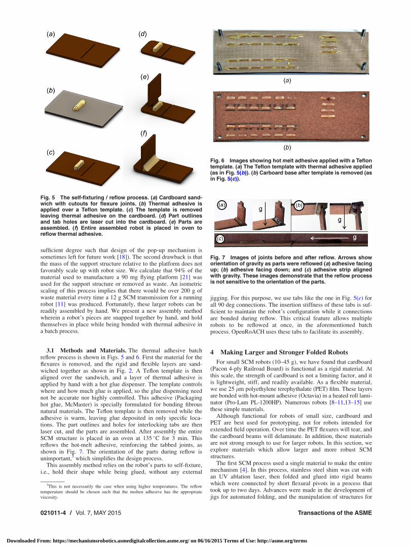
3.1 Methods and Materials. The thermal adhesive batchreflow process is shown in Figs. 5 and 6. First the material for theflexures is removed, and the rigid and flexible layers are sand-wiched together as shown in Fig. 2. A Teflon template is thenaligned over the sandwich, and a layer of thermal adhesive isapplied by hand with a hot glue dispenser. The template controlswhere and how much glue is applied, so the glue dispensing neednot be accurate nor highly controlled. This adhesive (Packaginghot glue, McMaster) is specially formulated for bonding fibrousnatural materials. The Teflon template is then removed while theadhesive is warm, leaving glue deposited in only specific loca-tions. The part outlines and holes for interlocking tabs are thenlaser cut, and the parts are assembled. After assembly the entireSCM structure is placed in an oven at 135 �C for 3 min. Thisreflows the hot-melt adhesive, reinforcing the tabbed joints, asshown in Fig. 7. The orientation of the parts during reflow isunimportant,3 which simplifies the design process.
This assembly method relies on the robot’s parts to self-fixture,i.e., hold their shape while being glued, without any external
jigging. For this purpose, we use tabs like the one in Fig. 5(e) forall 90 deg connections. The insertion stiffness of these tabs is suf-ficient to maintain the robot’s configuration while it connectionsare bonded during reflow. This critical feature allows multiplerobots to be reflowed at once, in the aforementioned batchprocess. OpenRoACH uses these tabs to facilitate its assembly.
4 Making Larger and Stronger Folded Robots
For small SCM robots (10–45 g), we have found that cardboard(Pacon 4-ply Railroad Board) is functional as a rigid material. Atthis scale, the strength of cardboard is not a limiting factor, and itis lightweight, stiff, and readily available. As a flexible material,we use 25 lm polyethylene terephythalate (PET) film. These layersare bonded with hot-mount adhesive (Octavia) in a heated roll lami-nator (Pro-Lam PL-1200HP). Numerous robots [8–11,13–15] usethese simple materials.
Although functional for robots of small size, cardboard andPET are best used for prototyping, not for robots intended forextended field operation. Over time the PET flexures will tear, andthe cardboard beams will delaminate. In addition, these materialsare not strong enough to use for larger robots. In this section, weexplore materials which allow larger and more robust SCMstructures.
The first SCM process used a single material to make the entiremechanism [4]. In this process, stainless steel shim was cut withan UV ablation laser, then folded and glued into rigid beamswhich were connected by short flexural pivots in a process thattook up to two days. Advances were made in the development ofjigs for automated folding, and the manipulation of structures for
Fig. 5 The self-fixturing / reflow process. (a) Cardboard sand-wich with cutouts for flexure joints. (b) Thermal adhesive isapplied over a Teflon template. (c) The template is removedleaving thermal adhesive on the cardboard. (d) Part outlinesand tab holes are laser cut into the cardboard. (e) Parts areassembled. (f) Entire assembled robot is placed in oven toreflow thermal adhesive.
Fig. 6 Images showing hot melt adhesive applied with a Teflontemplate. (a) The Teflon template with thermal adhesive applied(as in Fig. 5(b)). (b) Carboard base after template is removed (asin Fig. 5(c)).
Fig. 7 Images of joints before and after reflow. Arrows showorientation of gravity as parts were reflowed (a) adhesive facingup; (b) adhesive facing down; and (c) adhesive strip alignedwith gravity. These images demonstrate that the reflow processis not sensitive to the orientation of the parts.
3This is not necessarily the case when using higher temperatures. The reflowtemperature should be chosen such that the molten adhesive has the appropriateviscosity.
021011-4 / Vol. 7, MAY 2015 Transactions of the ASME
Downloaded From: https://mechanismsrobotics.asmedigitalcollection.asme.org/ on 06/16/2015 Terms of Use: http://asme.org/terms

small robots [23]. The problem with this version of SCM was thatone material had to act as both a rigid element and a flexible ele-ment, which limits the pool of appropriate materials. An insect’sexoskeleton is also composed of (largely) one material: chitin.However chitin in rigid portions of an exoskeleton is selectivelyreinforced with calcium carbonate [24] which forms a rigid com-posite. The exoskeleton therefore has effectively two materials:one rigid used for support, and one flexible used for joints.
In 2003, Wood et al. [5] extended the SCM process to use mul-tiple materials, one rigid (carbon fiber reinforced polymer) andone flexible (polyimide). This specialization of materialsdecreased the assembly complexity and increased the performance ofSCM robotic structures. At the time of writing, dynamic SCM micro-robots [18,22,25] still use these same basic materials. Recent work infolded robots has revisited one material structures [26,27], citingalignment as a difficult problem. We have found that dowel pins ena-ble an alignment accuracy of 8 lm between layers, which is suffi-cient for our robots which use a nominal flexure length of 300 lm.
SCM robots above the microscale, such as the 2.4 g crawlermini-RoACH [28], or a 1.1 g jumping robot [29] use fiberglass asa rigid material. Larger SCM structures were made out of fiber-glass because it can be quickly cut with an infrared laser. Carbonfiber is best cut with a UV ablation laser, and UV ablation laserson the market today have more limited working areas than theirinfrared counterparts, take longer to cut, and are more expensive.
4.1 Figures of Merit for SCM Materials. One limit whichwe impose on our choice of material is that it be readily machina-ble in an infrared laser cutter. This restriction ensures that our fab-rication methods require minimal specialty equipment. With thislimitation in mind, we explore options for both the rigid layersand the flexible layer.
We seek to establish figures of merit which relate materialproperties to high-quality folded robotic mechanisms. For kine-matic reliability, it is important that the rigid material be light-weight and rigid. We therefore seek maximum bending stiffnessfor minimum weight for the rigid material. This is equivalent to
maximizing the figure of merit Qb ¼ E1=2=q, where E is the flex-ural modulus of the material, and q is the density. We also con-
sider the failure strength figure of merit Qf ¼ r2=3f =q where rf is
the failure strength. Maximizing this figure of merit increases theforce capacity of the resultant mechanism. There are other practi-cal concerns for the rigid material such as its delaminationstrength, how easy it is to bond, the complexity of its production,and the toxicity of the products from its combustion (very relevantwhen the material is cut with an infrared laser).
From the flexible material, we desire maximum fracture tough-ness (or tear strength for a fabric), minimum damping, and mini-mum energy storage. Some energy storage in the joints may bedesirable at times, but it exacerbates nonlinear force generation inthe transmission and we find that it is usually best minimized.Another practical consideration is how easy the flexible material isto bond. For example, polypropylene would make excellent flex-ures (and is commonly used in injection molding for such a pur-pose) but it is difficult to bond without thermal welding processes.
4.2 Methods and Materials. We evaluated several new rigidmaterial options for the SCM process. Sandwich composites havelarge stiffness-to-weight ratios so we explored sandwich materialsthat met our fabrication criteria. Balsa wood is a good core mate-rial because it is stiff, low density, and cuts well with an infraredlaser. Face-sheets, which are more difficult to cut than the corematerial, cause fabrication difficulties. For example, G10 fiber-glass panels are cuttable with an infrared laser, but the high powerrequired to cut a G10-balsa sandwich composite burns out thecore material. We therefore fabricated several sandwich compo-sites with easy to cut face-sheets.
We used 1/16th balsa (Midwest Products) for the core material.Composites with three different face-sheets were made. The first
(B-PET) was made using 25 lm PET film adhered to the balsacore with hot mount thermal adhesive (Octavia) laminated at210 �F. The second face-sheet (B-P) was 20 lb copy paper. Tomake this composite we spread white glue on each side of thebalsa in as thin a layer as possible, and then applied the copypaper with a Nylon squeegee. The composite was then left to drywith small weights on top to avoid warping. The third face-sheet(B-P-CA) was prepared identically to the second but after drying,a thin layer of cyano-acrylate adhesive (Loctite 495) was appliedto the surface of the copy paper with a Nylon squeegee.
Three-point bending tests (ASTM D3043, shown in Figs. 8(a)and 9) performed in an Instron 5544 material testing machineestablished the flexural modulus and failure stress of each mate-rial.4 The balsa wood specimens were aligned such that the grainof the wood took the bending load.
For the flexible material, we evaluated the delaminationstrength of its bond to the rigid material candidates with a peeltest (ASTM D903, shown in Fig. 8(b)). Samples of uncoated 1.1oz ripstop Nylon5 (Ripstop by the Roll), and PET film (McMaster)were laminated to both cardboard and balsa wood with hot-mountthermal adhesive (Octavia) in a hot-roll laminator at 300 �F.
Ripstop nylon is difficult to bond with traditional methods. Thestrength of the bond is increased by laminating the ripstop Nylonwith hot-mount adhesive before including it in the compositesandwich. If a stronger bond is required, the Nylon should be des-sicated prior to use. As a hydrophilic polymer, Nylon contains sig-nificant amounts of water which can interfere with thethermoplastic hot-mount adhesive. We thoroughly dessicated ourripstop Nylon in a vacuum oven at 25 inHg and 65 �C for 1 hr.
Fig. 8 Images of experimental setups for material tests. (a)Bending test; (b) delamination test; and (c) crush test for theB-P-CA OpenRoACH, shown with a 1.9 kg load.
4Except cardboard, which did not fail in the bending test, because the specimenwas too compliant for the bending gauge length. Tensile strength is given instead.
5Ripstop Nylon is used in the commercialized version of DASH [3] (made byDASH Robotics).
Journal of Mechanisms and Robotics MAY 2015, Vol. 7 / 021011-5
Downloaded From: https://mechanismsrobotics.asmedigitalcollection.asme.org/ on 06/16/2015 Terms of Use: http://asme.org/terms

Other processing conditions with nonvacuum ovens should alsobe adequate.
Another strong flexure material is Cuben fabric (Ripstop by theRoll). It consists of ultrahigh molecular weight polyethylene fila-ments (known commercially as Spectra, or Dyneema) embeddedin a polyester matrix. It is not as strong as ripstop Nylon, but iseasier to work with; it can be swapped with PET film in any extantdesign without modifying the build procedure.
4.3 Results. Properties for candidate rigid materials areshown in Table 1. From left to right the columns list the density,flexural modulus, yield strength, and the figures of merit for stiff-ness and strength. Note that these are effective bulk material prop-erties for the entire laminate structure. All of the tested materialsappear in this table, as well as several other candidate materialsfor which typical properties are given. As a comparison, proper-ties for three common engineering materials (4140 Steel, Ti-6Al-4V Titanium, 0.6 fiber fraction UHM uniaxial carbon fiber), whichare not easily cuttable with an infrared laser, are also given.
Because of its low density, balsa wood was the best performingmaterial in terms of the stiffness figure of merit, Qb. However,this only considers loading along the fiber axis; the complianceacross the fibers is significantly greater. These orthotropic proper-ties are not desirable for the SCM process. The composites madewith balsa wood as a core were stiffer and more dense than thebalsa alone. They are comparable in terms of the figures of merit.In absolute terms, however, the balsa-paper-CA (B-P-CA) com-posite was the stiffest and strongest of the three. These propertieswere a result of the isotropic face sheet, which mitigates the ortho-tropic properties of the balsa wood core.
Of the materials which can be cut by an infrared laser, fiber-glass has the highest strength figure of merit. However commer-cially available fiberglass board is typically reinforced with epoxywhich produces harmful fumes when cut with an infrared laser. Itshould be noted that all tested materials outperformed cardboardin both categories.
The peel strength of the flexible material bonds is given inTable 2. All cardboard specimens failed by internal delaminationwhich indicates a material limit has been reached for the bondingof these materials. Slightly more cardboard came off on the Nylonthan the PET, which may explain the difference in peel strengths.The bonds to the balsa wood failed at the surface. The bondbetween Nylon and balsa was stronger than that between balsaand PET. The paper composites (B-P and B-P-CA) were alsotested for delamination strength. However, the bond between thebalsa wood and the paper was sufficiently strong such that thepaper failed before delamination, so the delamination strengthcould not be assessed.
Based on our findings on new materials for stronger and largerlegged robots, we built two OpenRoACH robots (See Sec. 2), onewith cardboard and one with the B-P-CA composite. To evaluatethe relative benefits of the two materials, we performed a staticcrush tests (shown in Fig. 8(c)) wherein weights were added to therobots until the chassis touched the ground. This test gives a mea-sure of the robot’s ability to carry loads. The cardboard robotwithstood 780 6 60 g before failure, the OpenRoACH made withthe new B-P-CA composite withstood 3350 6 250 g before fail-ure. Series compliance in the mechanisms, causing deflection ofthe legs was the predominant failure mode in these tests.
Other materials can be used to further extend SCM to largerstructures. Researchers at the University of Michigan6 haveworked to extend SCM up to the human scale as shown in Fig. 10.A sandwich composite material (Elmer’s white poster board)allowed for a high-stiffness to weight ratio. The flexures wereformed with fiber reinforced tape (3M 8959 and 3M 720). At thisscale, the researchers found that special considerations had to bemade for component stiffness, and some flexures required rein-forcing structures to avoid buckling. These researchers have
Table 1 Rigid material properties
Material q EB rF
Units kg/m3 GPa MPa Qb Qf
Cardboard 806 0.93 6 0.016 11.8 6 0.3 0.01 0.0066Balsa 84.1 0.85 6 0.12 8.32 6 1.7 0.35 0.048B-PET 185 2.41 6 0.29 22.1 6 4.9 0.27 0.042B-P 185 2.18 6 0.19 17.8 6 1.0 0.25 0.036B-P-CA 229 2.81 6 0.78 23.0 6 3.5 0.23 0.035aPET 1380 2.76 80.5 0.038 0.013aGFRPb 1800 50 1400 0.12 0.070
aSteel 7850 200 415 0.057 0.007aTitanium 4430 114 880 0.076 0.021aCFRPc 1660 294 840 0.326 0.053
aTypical value.bGlass fiber reinforced polymer.cCarbon fiber reinforced polymer.
Table 2 Delamination strength
Peel strength
Material N/mm
Cardboard-nylon 0.132 6 0.003Cardboard-PET 0.095 6 0.006Balsa-nylon 0.097 6 0.004Balsa-PET 0.030 6 0.003
Fig. 10 A meter long hexapedal SCM robot made in the BIRDSlab at the University of Michigan. Developed by Devin Miller, IanFitzner, and Shai Revzen, with thanks to Stacie Desousa.
Fig. 9 Structure of composites: (a) balsa-PET (B-PET) com-posite; (b) balsa-paper (B-P) composite; and (c) balsa-paper-CA(B-P-CA) composite
6http://www.birds.eecs.umich.edu/teaching/senior-project-2013-scm/
021011-6 / Vol. 7, MAY 2015 Transactions of the ASME
Downloaded From: https://mechanismsrobotics.asmedigitalcollection.asme.org/ on 06/16/2015 Terms of Use: http://asme.org/terms
shown that with appropriate material choice and design considera-tions, SCM can be extended to much larger structures than havebeen made previously.
5 Exoskeletons for Expendable Robots
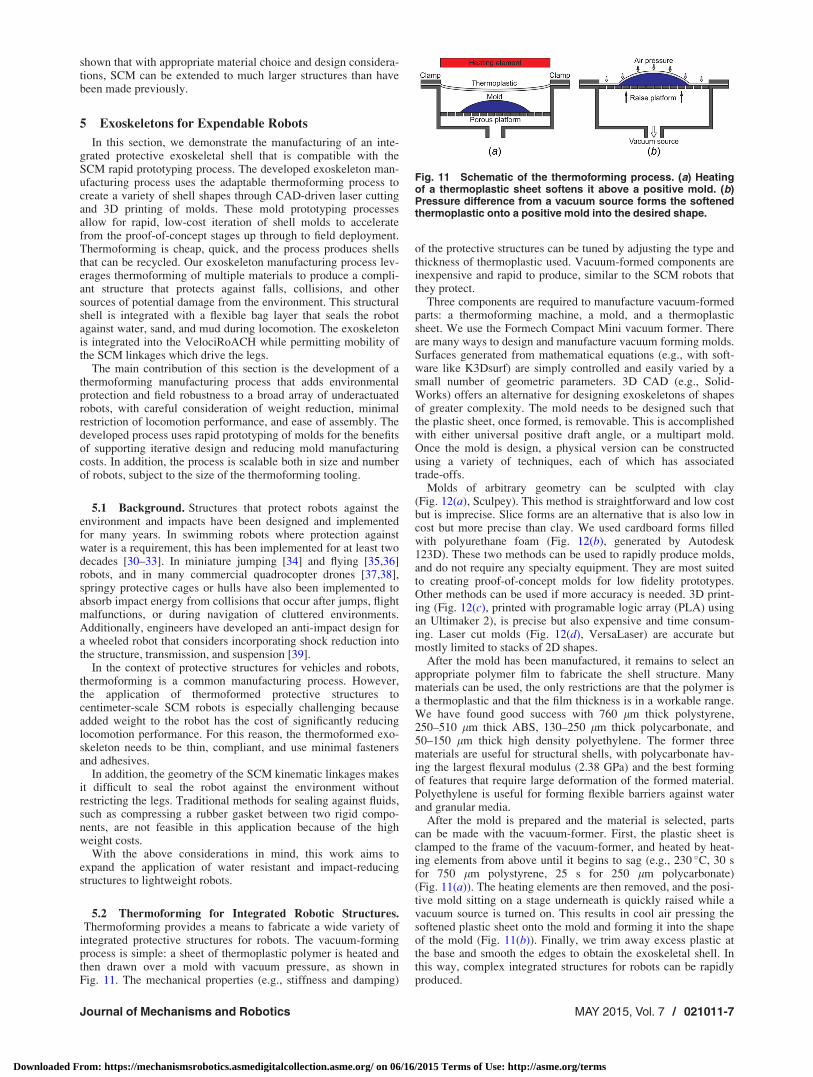
In this section, we demonstrate the manufacturing of an inte-grated protective exoskeletal shell that is compatible with theSCM rapid prototyping process. The developed exoskeleton man-ufacturing process uses the adaptable thermoforming process tocreate a variety of shell shapes through CAD-driven laser cuttingand 3D printing of molds. These mold prototyping processesallow for rapid, low-cost iteration of shell molds to acceleratefrom the proof-of-concept stages up through to field deployment.Thermoforming is cheap, quick, and the process produces shellsthat can be recycled. Our exoskeleton manufacturing process lev-erages thermoforming of multiple materials to produce a compli-ant structure that protects against falls, collisions, and othersources of potential damage from the environment. This structuralshell is integrated with a flexible bag layer that seals the robotagainst water, sand, and mud during locomotion. The exoskeletonis integrated into the VelociRoACH while permitting mobility ofthe SCM linkages which drive the legs.
The main contribution of this section is the development of athermoforming manufacturing process that adds environmentalprotection and field robustness to a broad array of underactuatedrobots, with careful consideration of weight reduction, minimalrestriction of locomotion performance, and ease of assembly. Thedeveloped process uses rapid prototyping of molds for the benefitsof supporting iterative design and reducing mold manufacturingcosts. In addition, the process is scalable both in size and numberof robots, subject to the size of the thermoforming tooling.
5.1 Background. Structures that protect robots against theenvironment and impacts have been designed and implementedfor many years. In swimming robots where protection againstwater is a requirement, this has been implemented for at least twodecades [30–33]. In miniature jumping [34] and flying [35,36]robots, and in many commercial quadrocopter drones [37,38],springy protective cages or hulls have also been implemented toabsorb impact energy from collisions that occur after jumps, flightmalfunctions, or during navigation of cluttered environments.Additionally, engineers have developed an anti-impact design fora wheeled robot that considers incorporating shock reduction intothe structure, transmission, and suspension [39].
In the context of protective structures for vehicles and robots,thermoforming is a common manufacturing process. However,the application of thermoformed protective structures tocentimeter-scale SCM robots is especially challenging becauseadded weight to the robot has the cost of significantly reducinglocomotion performance. For this reason, the thermoformed exo-skeleton needs to be thin, compliant, and use minimal fastenersand adhesives.
In addition, the geometry of the SCM kinematic linkages makesit difficult to seal the robot against the environment withoutrestricting the legs. Traditional methods for sealing against fluids,such as compressing a rubber gasket between two rigid compo-nents, are not feasible in this application because of the highweight costs.
With the above considerations in mind, this work aims toexpand the application of water resistant and impact-reducingstructures to lightweight robots.
5.2 Thermoforming for Integrated Robotic Structures.Thermoforming provides a means to fabricate a wide variety of
integrated protective structures for robots. The vacuum-formingprocess is simple: a sheet of thermoplastic polymer is heated andthen drawn over a mold with vacuum pressure, as shown inFig. 11. The mechanical properties (e.g., stiffness and damping)
of the protective structures can be tuned by adjusting the type andthickness of thermoplastic used. Vacuum-formed components areinexpensive and rapid to produce, similar to the SCM robots thatthey protect.
Three components are required to manufacture vacuum-formedparts: a thermoforming machine, a mold, and a thermoplasticsheet. We use the Formech Compact Mini vacuum former. Thereare many ways to design and manufacture vacuum forming molds.Surfaces generated from mathematical equations (e.g., with soft-ware like K3Dsurf) are simply controlled and easily varied by asmall number of geometric parameters. 3D CAD (e.g., Solid-Works) offers an alternative for designing exoskeletons of shapesof greater complexity. The mold needs to be designed such thatthe plastic sheet, once formed, is removable. This is accomplishedwith either universal positive draft angle, or a multipart mold.Once the mold is design, a physical version can be constructedusing a variety of techniques, each of which has associatedtrade-offs.
Molds of arbitrary geometry can be sculpted with clay(Fig. 12(a), Sculpey). This method is straightforward and low costbut is imprecise. Slice forms are an alternative that is also low incost but more precise than clay. We used cardboard forms filledwith polyurethane foam (Fig. 12(b), generated by Autodesk123D). These two methods can be used to rapidly produce molds,and do not require any specialty equipment. They are most suitedto creating proof-of-concept molds for low fidelity prototypes.Other methods can be used if more accuracy is needed. 3D print-ing (Fig. 12(c), printed with programable logic array (PLA) usingan Ultimaker 2), is precise but also expensive and time consum-ing. Laser cut molds (Fig. 12(d), VersaLaser) are accurate butmostly limited to stacks of 2D shapes.
After the mold has been manufactured, it remains to select anappropriate polymer film to fabricate the shell structure. Manymaterials can be used, the only restrictions are that the polymer isa thermoplastic and that the film thickness is in a workable range.We have found good success with 760 lm thick polystyrene,250–510 lm thick ABS, 130–250 lm thick polycarbonate, and50–150 lm thick high density polyethylene. The former threematerials are useful for structural shells, with polycarbonate hav-ing the largest flexural modulus (2.38 GPa) and the best formingof features that require large deformation of the formed material.Polyethylene is useful for forming flexible barriers against waterand granular media.
After the mold is prepared and the material is selected, partscan be made with the vacuum-former. First, the plastic sheet isclamped to the frame of the vacuum-former, and heated by heat-ing elements from above until it begins to sag (e.g., 230 �C, 30 sfor 750 lm polystyrene, 25 s for 250 lm polycarbonate)(Fig. 11(a)). The heating elements are then removed, and the posi-tive mold sitting on a stage underneath is quickly raised while avacuum source is turned on. This results in cool air pressing thesoftened plastic sheet onto the mold and forming it into the shapeof the mold (Fig. 11(b)). Finally, we trim away excess plastic atthe base and smooth the edges to obtain the exoskeletal shell. Inthis way, complex integrated structures for robots can be rapidlyproduced.
Fig. 11 Schematic of the thermoforming process. (a) Heatingof a thermoplastic sheet softens it above a positive mold. (b)Pressure difference from a vacuum source forms the softenedthermoplastic onto a positive mold into the desired shape.
Journal of Mechanisms and Robotics MAY 2015, Vol. 7 / 021011-7
Downloaded From: https://mechanismsrobotics.asmedigitalcollection.asme.org/ on 06/16/2015 Terms of Use: http://asme.org/terms

5.3 Shells for Traversing Cluttered Terrain. A recent studyhas discovered that insects like discoid cockroaches have thin,rounded body shapes that assist their traversal through clutteredterrain such as grasslike beams, by facilitating passive body-rolling to align the smallest body dimensions with obstacle gaps(for more details of the animal experiments, see Ref. [40]).Inspired by this discovery, we designed and fabricated a simpletop exoskeletal shell of similar shape to the cockroach to enableSCM robots to traverse similar cluttered terrain.
5.3.1 Design of the Traversal-Assisting Shell. This simple topshell is a thin slice of an ellipsoid, as shown in Fig. 13. It has simi-lar overall aspect ratios (length:width:height¼ 6:4:1) to the exo-skeleton of the discoid cockroach (7:3.5:1). It is slightly wider(relative to the animal) to fully enclose the perimeter of the Veloc-iRoACH body. We hypothesized that maintaining shell shape isimportant in this application, so we chose 750 lm polystyrenesheets (McMaster) as a suitable material to create a relatively rigidshell.
5.3.2 Methods and Materials. A high-fidelity shell was notrequired for this proof of concept experiment, so the mold wasfabricated with hand-sculpted clay (Sculpey). The clay mold wasbaked in an oven at 130 �C for 70 min, and polished to obtain asmooth surface. We fabricated a prototype shell by thermoform-ing a polystyrene sheet over the hand-sculpted mold, and then
trimming it to size. The shell was mounted onto the robot usingVelcro pads.
5.3.3 Characterization. To characterize the effectiveness ofthe exoskeletal shell in assisting cluttered terrain traversal, wechallenged the robot to run though cluttered grasslike beamobstacles. With its original cuboidal body, VelociRoACH trav-ersed with a 15% chance of success, even though the obstacle gapwas wider than the robot body width. By contrast, VelociRoACHwith the simple, rounded exoskeletal top shell passively rolled itsbody to the side in similar fashion as the cockroaches [40] andtraversed the same cluttered terrain with a 90% success rate. With-out any sensory feedback or changes in motor control, this inte-grated structure improved the VelociRoACH’s ability to traversecluttered terrain. While the shell adds significant weight to therobot (19 g shell weight vs. 26 g body weight), the robot’s velocitydoes not decrease during running on open ground (60 cm/s with orwithout shell at 10 Hz). More details of the robot experimentalsetup, protocols, and results are described in Ref. [2].
Further, given the fabricated mold (�hours, �$10), the cost intime (�minutes) and materials (�$1 per shell) for this shell fabri-cation process is significantly lower compared to existing techni-ques for navigation through cluttered environments, such asmapping and path planning. These techniques usually requireadditional sensors, computers, and actuators, and have long devel-opment and testing cycles. This makes the exoskeletal shell com-patible with the low cost, dispensable applications of SCM robots.
5.4 Flexible Environmental Protection. For operation ofSCM robots in potentially harmful environments, we want to addprotection from water and granular media without limiting themotion of the robot. Flexible environmental protection alsoextends to protecting the environment from the robot for biomedi-cal applications. However, we do not want to simply encapsulatethe whole robot in a flexible layer because there needs to be aninterface for the appendages to interact with the environment. Forconvenience, we also want the option to have the flexible shell beresealable.
5.4.1 Design of the Water Resistant Shell. We designed theflexible layer as a custom shaped “bag” made from high densitypolyethylene. This material has the benefits of being able to beformed on a thermoforming machine, and being able to be heatwelded with a hand heat sealer (Audion Elektro). We assumedthat the bag was inextensible and designed the bottom layer of thepolyethylene bag to allow the robot mechanisms to move freelyby adding the appropriate amount of slack. The geometry of thethermoformed bottom bag layer is shown in Fig. 14. An image ofa robot leg passed through a protruding section of the bottom baglayer is shown in Fig. 15(b).
Fig. 13 Simple top shell for traversing cluttered terrain. (a)Design of shell shape resembling a thin slice of an ellipsoid. (b)Side view of VelociRoACH with the simple top shell.
Fig. 12 Top: molds constructed using (a) clay modeling, (b) slice forms, (c) 3D printing,and (d) laser cutting. Bottom: exoskeleton shells made from these molds by thermoform-ing using ((a) and (b)) 750 lm polystyrene, (c) 250 lm polycarbonate, and (d) 50 lmpolyethylene.
021011-8 / Vol. 7, MAY 2015 Transactions of the ASME
Downloaded From: https://mechanismsrobotics.asmedigitalcollection.asme.org/ on 06/16/2015 Terms of Use: http://asme.org/terms

There are several options to make the flexible layer resistant orimpervious to the environment. If the robot needs to be water-proof, it can be fully heat sealed inside the bag. This approach pre-cludes easy maintenance access to the robot. Water-resistantpolyethylene zippers can be incorporated into the flexible layer toprovide a reclosable seal against the environment, as shown inFig. 19(c). This zipper leaks when submerged at depth in liquid,making the shielding merely water resistant, and not waterproof.
Our interface from the inside of the sealed bag is a two-partsnap fit attachment. Half of the interface is attached to the robothip inside the flexible bag layer. The other half is outside the baglayer and snaps into the inner piece, wedging the bag layerbetween the two components. A cross section of the cast polyur-ethane segmented leg mount that is designed for this purpose isshown in Fig. 15. Modular legs for the robot slide into dovetailconnections on the outer components.
5.4.2 Methods and Materials. The process for manufacturingthe flexible bag layer of the protective shell is shown in Fig. 14.The process begins by thermoforming protrusions into one side ofa 51 lm thick split polyethylene zipper bag (Fig. 14(a)). Next,volume to accommodate the robot is thermoformed into the otherside of the bag (Fig. 14(b)). Then, the zipper halves are joined anda hand heat sealer (Audion Elektro) is used to heat weld the threeedges of the bag (welding through the zipper on the sides) and thebag is cut at the outer extent of the heat weld (Fig. 14(c)). Theformed flexible bag layer protects the robot from water and granu-lar terrain, is resealable, and allows for legged locomotion inconjunction with the leg mounts shown in Fig. 15.
5.4.3 Characterization. To test that the resealable polyethyl-ene bag provides protection against the intrusion of granularmedia and water, VelociRoACH was inserted into the flexible baglayer and protective shell (following the procedure in Fig. 19) andrun over both poppy seeds, and shallow water.
First, the robot ran for 5 min at full motor power through a2.5 cm thick layer of poppy seeds. Approximately 6 g of poppyseeds accumulated in the structural shell of the robot, but no seedswere inside the polyethylene bag.
Next, VelociRoACH ran in place for 3 min a container filled toa height of 1 cm with water. The electronics and SCM mecha-nisms survived the test. However, some water droplets wereobserved inside the bag layer and there was some wetting of thelower cardboard structures. Upon inspection after the test, the baglayer appeared to have small perforations from the leg clips thatallowed water to enter. From a separate evaluation of the zipper, itadmits some water when submerged in shallow water, so it isanother potential source of failure of the water seal.
To fully waterproof the robot we would omit the zipper andfully heat seal the robot into the bag. This comes at the cost of there-usability of the bag layer. In addition, we would need to placeshielding materials such as rubber or foam at any sharp interfacesthat could potentially perforate the bag.
5.5 Protective Shell. The structural layer of the protectiveshell is designed to reduce the shock imparted to the robot byimpacts while satisfying the constraints that it fits around the robotstructure, and does not interfere with the motion of the legs.
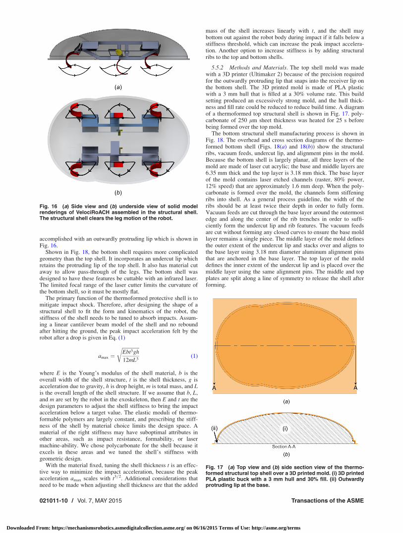
5.5.1 Design of the Protective Shell. The protective shell issplit into a bottom and top section that are thermoformed sepa-rately. The top shell (shown in Fig. 16) is designed such that itdoes not interfere with the VelociRoACH’s SCM linkages. Thisleaves the design space mostly open. We chose an ellipsoidal shellshape that we expect to enable the higher order locomotory capa-bilities described in Sec. 5.3 while being capable of absorbingimpact from high-speed collisions.
Shown in Fig. 16, a kinematic model of the VelociRoACHtransmission was used to trace out the trajectories of the leg tipsof the robot. These trajectories are used in conjunction with thesolid model geometry to shape the shell volume such that there isno interference of any mechanisms or leg with the shell. Duringthis process, a secondary ellipsoidal bulb was added to the frontshell volume in order to clear the forward part of the front legstroke. The top shell also needs an interface to the bottom shell.We chose to use an integrated snap-fit ring along the bottom edgeof the top shell. This approach has the advantage that it is reclos-able, and requires no adhesives. On the top shell, this feature is
Fig. 15 Leg mounts that clip through the sealed bag layer: (a)diagram with details (i) half of the leg mount is attached to therobot hip inside the bag layer, (ii) the other half of the leg mountis outside the bag layer and snaps into the inner component,(iii) bag layer wedges between the two leg mount halves, (iv)VelociRoACH legs slide into dovetail connections on the outercomponent; and (b) close-up of molded leg clips capturing thesealing bag on the robot
Fig. 14 Sealed bag layer manufacturing process. (a) Side view:forming of the bottom of bag layer with protrusions for freedomof leg motion; (b) side view: forming of the top of bag layer; (c)underside view: bag layer assembly with details (i) bottompiece of the bag, (ii) top piece of the bag, (iii) joining “ziploc”zipper on the bag, (iv) heat welds at the edge of the two layers,(v) formed out-of-plane pockets, shown topologically in thisview, and (vi) extra vertical webs that form in the contoured baglayer between peaks, due to the high aspect ratio of the mold.
Journal of Mechanisms and Robotics MAY 2015, Vol. 7 / 021011-9
Downloaded From: https://mechanismsrobotics.asmedigitalcollection.asme.org/ on 06/16/2015 Terms of Use: http://asme.org/terms
accomplished with an outwardly protruding lip which is shown inFig. 16.
Shown in Fig. 18, the bottom shell requires more complicatedgeometry than the top shell. It incorporates an undercut lip whichretains the protruding lip of the top shell. It also has material cutaway to allow pass-through of the legs. The bottom shell wasdesigned to have these features be cuttable with an infrared laser.The limited focal range of the laser cutter limits the curvature ofthe bottom shell, so it must be mostly flat.
The primary function of the thermoformed protective shell is tomitigate impact shock. Therefore, after designing the shape of astructural shell to fit the form and kinematics of the robot, thestiffness of the shell needs to be tuned to absorb impacts. Assum-ing a linear cantilever beam model of the shell and no reboundafter hitting the ground, the peak impact acceleration felt by therobot after a drop is given in Eq. (1)
amax ¼ffiffiffiffiffiffiffiffiffiffiffiffiffiffiEbt3gh
12mL3
r(1)
where E is the Young’s modulus of the shell material, b is theoverall width of the shell structure, t is the shell thickness, g isacceleration due to gravity, h is drop height, m is total mass, and Lis the overall length of the shell structure. If we assume that b, L,and m are set by the robot in the exoskeleton, then E and t are thedesign parameters to adjust the shell stiffness to bring the impactacceleration below a target value. The elastic moduli of thermo-formable polymers are largely constant, and prescribing the stiff-ness of the shell by material choice limits the design space. Amaterial of the right stiffness may have suboptimal attributes inother areas, such as impact resistance, formability, or lasermachine-ability. We chose polycarbonate for the shell because itexcels in these areas and we tuned the shell’s stiffness withgeometric design.
With the material fixed, tuning the shell thickness t is an effec-tive way to minimize the impact acceleration, because the peakacceleration amax scales with t3=2. Additional considerations thatneed to be made when adjusting shell thickness are that the added
mass of the shell increases linearly with t, and the shell maybottom out against the robot body during impact if it falls below astiffness threshold, which can increase the peak impact accelera-tion. Another option to increase stiffness is by adding structuralribs to the top and bottom shells.
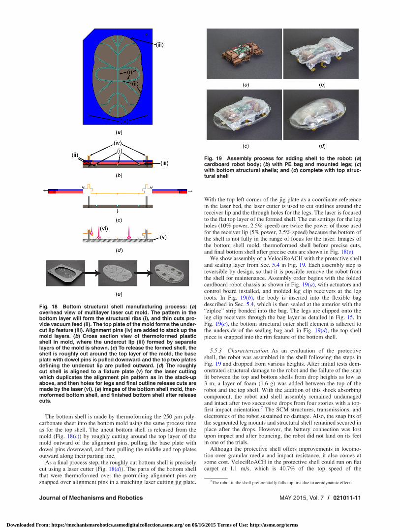
5.5.2 Methods and Materials. The top shell mold was madewith a 3D printer (Ultimaker 2) because of the precision requiredfor the outwardly protruding lip that snaps into the receiver lip onthe bottom shell. The 3D printed mold is made of PLA plasticwith a 3 mm hull that is filled at a 30% volume rate. This buildsetting produced an excessively strong mold, and the hull thick-ness and fill rate could be reduced to reduce build time. A diagramof a thermoformed top structural shell is shown in Fig. 17. poly-carbonate of 250 lm sheet thickness was heated for 25 s beforebeing formed over the top mold.
The bottom structural shell manufacturing process is shown inFig. 18. The overhead and cross section diagrams of the thermo-formed bottom shell (Figs. 18(a) and 18(b)) show the structuralribs, vacuum feeds, undercut lip, and alignment pins in the mold.Because the bottom shell is largely planar, all three layers of themold are made of laser cut acrylic; the base and middle layers are6.35 mm thick and the top layer is 3.18 mm thick. The base layerof the mold contains laser etched channels (raster, 80% power,12% speed) that are approximately 1.6 mm deep. When the poly-carbonate is formed over the mold, the channels form stiffeningribs into shell. As a general process guideline, the width of theribs should be at least twice their depth in order to fully form.Vacuum feeds are cut through the base layer around the outermostedge and along the center of the rib trenches in order to suffi-ciently form the undercut lip and rib features. The vacuum feedsare cut without forming any closed curves to ensure the base moldlayer remains a single piece. The middle layer of the mold definesthe outer extent of the undercut lip and stacks over and aligns tothe base layer using 3.18 mm diameter aluminum alignment pinsthat are anchored in the base layer. The top layer of the molddefines the inner extent of the undercut lip and is placed over themiddle layer using the same alignment pins. The middle and topplates are split along a line of symmetry to release the shell afterforming.
Fig. 16 (a) Side view and (b) underside view of solid modelrenderings of VelociRoACH assembled in the structural shell.The structural shell clears the leg motion of the robot.
Fig. 17 (a) Top view and (b) side section view of the thermo-formed structural top shell over a 3D printed mold. (i) 3D printedPLA plastic buck with a 3 mm hull and 30% fill. (ii) Outwardlyprotruding lip at the base.
021011-10 / Vol. 7, MAY 2015 Transactions of the ASME
Downloaded From: https://mechanismsrobotics.asmedigitalcollection.asme.org/ on 06/16/2015 Terms of Use: http://asme.org/terms
The bottom shell is made by thermoforming the 250 lm poly-carbonate sheet into the bottom mold using the same process timeas for the top shell. The uncut bottom shell is released from themold (Fig. 18(c)) by roughly cutting around the top layer of themold outward of the alignment pins, pulling the base plate withdowel pins downward, and then pulling the middle and top platesoutward along their parting line.
As a final process step, the roughly cut bottom shell is preciselycut using a laser cutter (Fig. 18(d)). The parts of the bottom shellthat were thermoformed over the protruding alignment pins aresnapped over alignment pins in a matching laser cutting jig plate.
With the top left corner of the jig plate as a coordinate referencein the laser bed, the laser cutter is used to cut outlines around thereceiver lip and the through holes for the legs. The laser is focusedto the flat top layer of the formed shell. The cut settings for the legholes (10% power, 2.5% speed) are twice the power of those usedfor the receiver lip (5% power, 2.5% speed) because the bottom ofthe shell is not fully in the range of focus for the laser. Images ofthe bottom shell mold, thermoformed shell before precise cuts,and final bottom shell after precise cuts are shown in Fig. 18(e).
We show assembly of a VelociRoACH with the protective shelland sealing layer from Sec. 5.4 in Fig. 19. Each assembly step isreversible by design, so that it is possible remove the robot fromthe shell for maintenance. Assembly order begins with the foldedcardboard robot chassis as shown in Fig. 19(a), with actuators andcontrol board installed, and molded leg clip receivers at the legroots. In Fig. 19(b), the body is inserted into the flexible bagdescribed in Sec. 5.4, which is then sealed at the anterior with the“ziploc” strip bonded into the bag. The legs are clipped onto theleg clip receivers through the bag layer as detailed in Fig. 15. InFig. 19(c), the bottom structural outer shell element is adhered tothe underside of the sealing bag and, in Fig. 19(d), the top shellpiece is snapped into the rim feature of the bottom shell.
5.5.3 Characterization. As an evaluation of the protectiveshell, the robot was assembled in the shell following the steps inFig. 19 and dropped from various heights. After initial tests dem-onstrated structural damage to the robot and the failure of the snapfit between the top and bottom shells from drop heights as low as3 m, a layer of foam (1.6 g) was added between the top of therobot and the top shell. With the addition of this shock absorbingcomponent, the robot and shell assembly remained undamagedand intact after two successive drops from four stories with a top-first impact orientation.7 The SCM structures, transmissions, andelectronics of the robot sustained no damage. Also, the snap fits ofthe segmented leg mounts and structural shell remained secured inplace after the drops. However, the battery connection was lostupon impact and after bouncing, the robot did not land on its feetin one of the trials.
Although the protective shell offers improvements in locomo-tion over granular media and impact resistance, it also comes atsome cost. VelociRoACH in the protective shell could run on flatcarpet at 1.1 m/s, which is 40.7% of the top speed of the
Fig. 18 Bottom structural shell manufacturing process: (a)overhead view of multilayer laser cut mold. The pattern in thebottom layer will form the structural ribs (i), and thin cuts pro-vide vacuum feed (ii). The top plate of the mold forms the under-cut lip feature (iii). Alignment pins (iv) are added to stack up themold layers. (b) Cross section view of thermoformed plasticshell in mold, where the undercut lip (iii) formed by separatelayers of the mold is shown. (c) To release the formed shell, theshell is roughly cut around the top layer of the mold, the baseplate with dowel pins is pulled downward and the top two platesdefining the undercut lip are pulled outward. (d) The roughlycut shell is aligned to a fixture plate (v) for the laser cuttingwhich duplicates the alignment pin pattern as in the stack-upabove, and then holes for legs and final outline release cuts aremade by the laser (vi). (e) Images of the bottom shell mold, ther-moformed bottom shell, and finished bottom shell after releasecuts.
Fig. 19 Assembly process for adding shell to the robot: (a)cardboard robot body; (b) with PE bag and mounted legs; (c)with bottom structural shells; and (d) complete with top struc-tural shell
7The robot in the shell preferentially falls top first due to aerodynamic effects.
Journal of Mechanisms and Robotics MAY 2015, Vol. 7 / 021011-11
Downloaded From: https://mechanismsrobotics.asmedigitalcollection.asme.org/ on 06/16/2015 Terms of Use: http://asme.org/terms

unencumbered robot [11]. The shell adds a total of 13.5 g of mass(10.7 g structural layer, 2.7 g bag layer) to the 30.1 g robot (withbattery and board). Also, the shell increases the length by widthby height dimensions of the robot from 10 cm � 7 cm � 4.5 cm to18.5 cm � 12 cm � 5.3 cm.
6 Claws
Numerous robots have used claws to climb walls [14,41,42] orwalk over adverse terrain [1]. These claws were inspired by aniso-tropic spines found on the legs of cockroaches and arthropods [1],shown in Fig. 20. In this section, we present a method to rapidlyfabricate arrays of anisotropic claws.
6.1 Methods and Materials. The claws are made by cuttingtriangles with an inner angle of 45 deg into 125 lm thick fiber-glass sheet with a UV laser (PMI) as shown in Fig. 21. This shapeallows for anisotropic engagement forces which allow the robot tolift its leg off the ground more freely. After the claws have beencut they are mounted onto the curved legs of the robot, at whichpoint the claws are revealed as shown in Fig. 21. The claws are
adhered so that the sloped edge of the triangle is always on theouter side of the robot.
6.2 Characterization. Load-drag-pull tests were performedin the fore-aft and lateral directions on a robot leg with integratedclaws. The recorded force profile (Fig. 22) shows the normal load-ing force Fz, the fore-aft force Fy, and the lateral force Fx. A loadof 0.2 N is required to disengage the corkboard while the clawsare penetrating the surface. The claws can be released with a forceof 0.1 N, for a 2:1 ratio between holding and releasing force(Fig. 23). Less force was required to disengage the foot in thedirection of the sloped edge, as compared to the side with astraight edge. To evaluate their utility on a robotic platform, theclaws were mounted to a VelociRoACH, a hexapedal terrestrialrobot [11], to test functionality. This work is described in a futurepaper.
7 Tactile Sensors for SCM Robots
Legged SCM millirobots can operate in rough terrain, confinedspaces and in the presence of obstacles such as foliage. To operateeffectively in such difficult and uncertain environments, tactilesensory feedback from surfaces with which they interact is useful.Two SCM-compatible tactile sensors were developed to providesuch information. The first is a binary, hair-based sensor array,which uses bio-inspired polymer hairs to detect both normal and
Fig. 20 Cockroach (B. discoidalis) leg spines. Arrows indicatethe direction of the force applied to the spines.
Fig. 21 Process to create the claws. Figures (a) and (b) are pic-tures of the fabricated components. To make the legs, the out-line of the claws was first laser-cut into a rectangle offiberglass. (a) Then the fiberglass was glued onto a curved leg.(b) Claws stick out because the fiberglass remains flat in thereleased sections.
Fig. 22 Plot of the forces exerted by the claw onto a test sub-strate as it is pulled in the Fx and Fy directions and preloadedwith Fz. Fy indicates the fore-aft forces while Fx shows lateralforces.
Fig. 23 The forces required to disengage the spines from a pi-ece of corkboard. The arrows indicate the disengagementforce’s direction.
021011-12 / Vol. 7, MAY 2015 Transactions of the ASME
Downloaded From: https://mechanismsrobotics.asmedigitalcollection.asme.org/ on 06/16/2015 Terms of Use: http://asme.org/terms

shear contact forces. The second is an analog tactile bumper capa-ble of measuring contact forces when bumping into obstacles.
7.1 Binary Hair Array. A 5� 4 binary hair sensor array8
was developed to provide SCM robots with the ability to detectcontact with ground obstacles (Fig. 24). The sensor consists of anarray of highly sensitive binary contact switches, where eachswitch is activated by a compliant polymer hair originating fromthe tip of the switch. The sensor can be fabricated using anentirely laminar roll-to-roll process that is compatible with theSCM fabrication methodology.
Each hair sensor consists of a lever arm (B) of rigid structuralmaterial hinged at one end through a polymer flexure (C). Thesensor array discussed here uses four-ply cardboard (0.4 mmthick) as the structural material and 75 lm-thick PET film for theflexure hinges. Curled polymer hairs (A) are held in place at thetip of each switch lever by small blocks of cardboard that, to-gether with adhesive, adhere the roots of the hairs to the lever tips.When the hairs are perturbed, either through normal or shear con-tact forces, the levers deflect downward, pivoting at their flexurehinges, bringing two copper layers (D) into contact. (Fig. 25)
7.1.1 Manufacturing. A key design feature of the hair sensorarray is that it can be fabricated using an entirely laminar process,in which the full sensor is assembled by stacking up layers of ma-terial via lamination, while forming the required mechanical fea-tures on the accumulating stack-up using a laser-cutter. Overall,the hair sensor array is the product of 13 separate layers that stacktogether to form the electrical contacts, switch levers and hairs(Fig. 26). The curled hairs are formed by laminating a precurledfilm composite consisting of 25 lm polypropylene (PP) laminatedtogether with 50 lm low-density polyethylene (LDPE). Whenlaminated at a temperature of 177 �C and a pressure of 345 kPa,the two polymer films fuse together to form a composite with anatural radius of curvature of 3–4 mm.
7.1.2 Characterization. The average sensitivity of the hair-switches in the array was characterized by determining the mini-mum threshold weight at which different sized patches of hairsbecome active. Here, a patch of hairs was labeled as active if atleast 2/3 of the loaded hairs were active. The results are plotted inFig. 27. The dashed trend line is the least-squares fit (zero
intercept) to the data points, indicating an average normal sensi-tivity of 0.79 g/hair.
7.2 Force-Sensing Taxel Array. To complement the contactsensor array, an analog force-sensing taxel array was developedfor measuring the magnitude of contact forces. The analog tactilesensor consists of an array of rapidly manufactured force-sensingelements, arranged on a cylindrical bumper structure that attachesto the front of a legged millirobot (Fig. 28).
The tactile bumper consists of a 2� 7 array of force-sensingtaxels attached to the front of the hexapedal millirobot through acardboard mounting structure. Each taxel consists of a reflectiveMylar-film patch supported on foam walls above a Sharp GP2S60proximity sensor (Fig. 29). The force-sensing taxels are designedto exhibit two sensitivity regions, meaning that they have greatersensitivity at small deformation, to detect smaller contact forces,and then become less sensitive at larger deformation, to increasethe saturation force.
7.2.1 Manufacturing. The foam sensory structures that sitabove the array of proximity sensors are formed through a laminarprocess involving the incremental build-up of features throughlamination and laser cutting (Fig. 30). To begin, a patterned layerof sheet adhesive is laminated to a cardboard base, and regions ofthe adhesive are exposed by scoring via laser, and removing por-tions of the paper backing. The exposed adhesive regions are usedto anchor down 2.6 mm thick inner foam wall features. Taller,outer foam walls are formed by laminating an approximately 3.2mm thick patterned foam sheet to a 50 lm thick reflective Mylar-film, and then laminating the foam–Mylar stack-up to the baselayer. Individual taxel structures are isolated from one another by
Fig. 25 Hair-activated switch in open (top) and closed (bottom)configurations. Sensor consists of curled polymer hair (A), rigidlever arm (B), polymer flexure (C), and copper contacts (D) [43].
Fig. 26 Layers that comprise the hair sensor array: (A) baselayer, (B) bottom contacts, (C) spacer, (D) insulating polymerfilm, (E) spacer (F), top contacts, (G) paper backing, (H) flexurepolymer film, (I) switch levers, (J) precut sheet adhesive, (K)prestressed hair film (L), precut sheet adhesive, and (M) hairmounting layer [43]
Fig. 27 Total loading required for sensor activation as a func-tion of the number of hairs loaded [43]
Fig. 24 (Left) 5 3 4 array of binary hair sensors. (Right) Hairsensor array mounted to bottom of hexapedal SCM robot [43].
8Some of the information presented for the binary hair array is a refinement ofwork that was previously presented at a conference [43].
Journal of Mechanisms and Robotics MAY 2015, Vol. 7 / 021011-13
Downloaded From: https://mechanismsrobotics.asmedigitalcollection.asme.org/ on 06/16/2015 Terms of Use: http://asme.org/terms

laser-cutting their outlines into the Mylar and foam and peelingaway the excess material left in between.
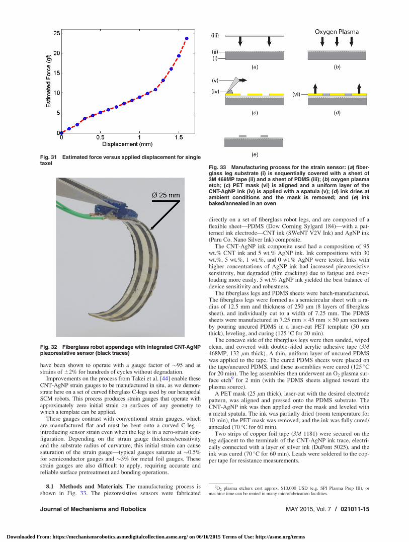
7.2.2 Characterization. To characterize the sensitivity of thefoam taxel structures, the response of a single taxel was recordedover a range of statically applied loads and displacements. These
data were combined using the response-to-load data as a calibra-tion for estimating the forces corresponding to the applied dis-placements. The result is the sensitivity characterization curveshown in Fig. 31, which highlights the dual-sensitivity of thefoam taxels.
8 Legs With Integrated Load Sensing
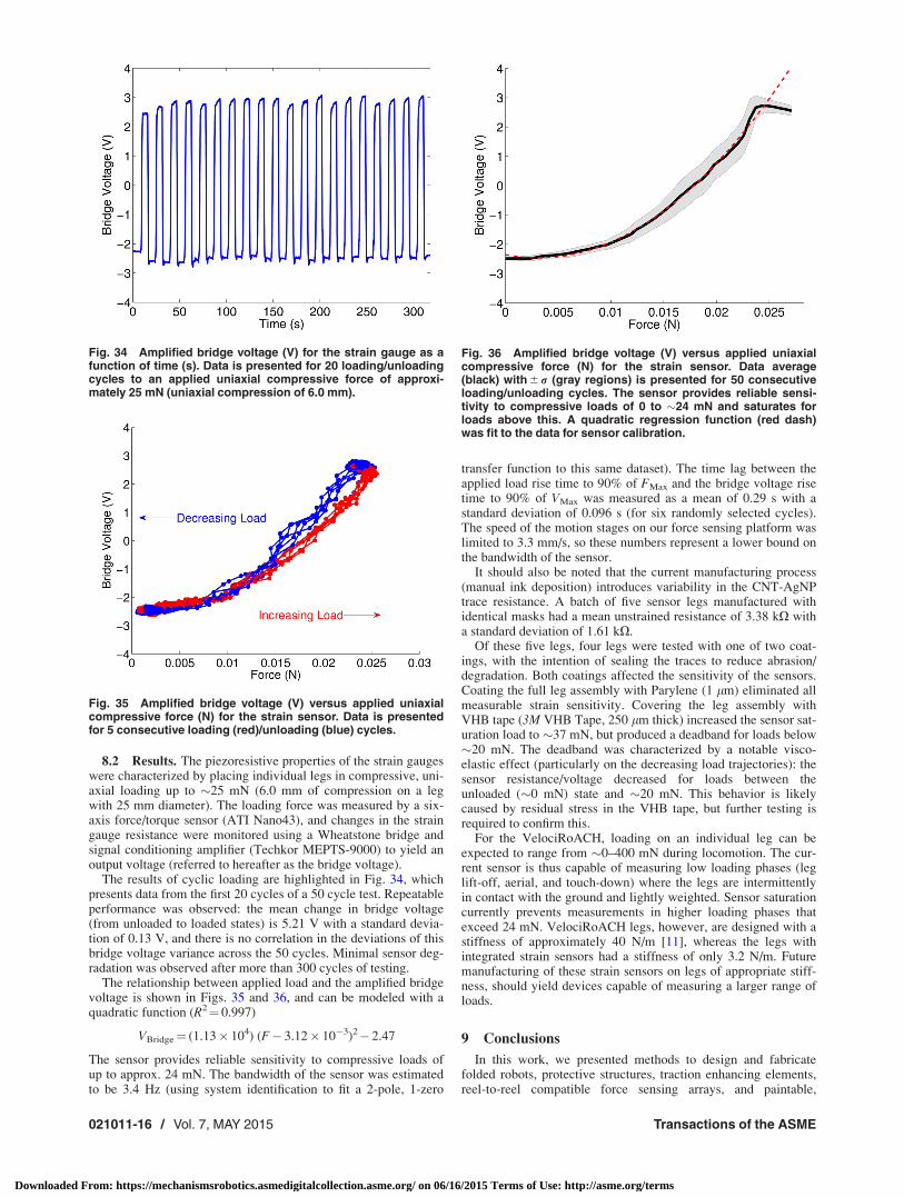
The ability to estimate applied forces in either biological orrobotic systems is useful, with direct applications in manipulation,optimal control, and estimating contact interactions with nonrigidobjects. To this end, we developed a process to create fiberglassrobotic appendages with flexible, piezoresistive strain gauges thatare fabricated in situ (Fig. 32).
Compact, flexible piezoresistive sensors have been developedfor high-sensitivity strain measurements by Takei et al. [44]. Thesensors consist of a particle desorption mass spectrometry(PDMS) substrate with a printed strain-sensitive CNT/silver nano-particle (CNT-AgNP) composite ink coating. The strain sensors
Fig. 28 (Left) Force-sensing taxel array. (Center) Bumper attached to front of hexapedalSCM robot. (Right) Three subcomponents of bumper: cardboard mounting structure (A),array of proximity sensors on flex-circuit (B), and outer layer of foam sensory structures (C).
Fig. 29 Cross section illustration of force-sensing bumpertaxel. Taxel structure consists of 50 lm thick reflective Mylar-film (A), outer and inner urethane foam walls (B), foam-supporting cardboard layer (C), sharp GP2S60 proximity sensoron flex circuit (D), and bumper mounting structure (E).
Fig. 30 Laminar fabrication of sensory foam structures: Patterned cardboard base forfoam structures (a), patterned sheet adhesive laminated over base (b), regions of adhe-sive exposed for anchoring inner foam walls (c), foam strips laminated down ontoexposed adhesive regions (d), inner foam walls laser-cut from foam strips (e), taller, pat-terned foam laminated onto reflective Mylar-film (f), taller foam laminated onto base (g),and foam structures are isolated by cutting through Mylar-film and underlying foam, butnot cardboard base, and peeling away excess material ((h) and (i))
021011-14 / Vol. 7, MAY 2015 Transactions of the ASME
Downloaded From: https://mechanismsrobotics.asmedigitalcollection.asme.org/ on 06/16/2015 Terms of Use: http://asme.org/terms
have been shown to operate with a gauge factor of �95 and atstrains of 62% for hundreds of cycles without degradation.
Improvements on the process from Takei et al. [44] enable theseCNT-AgNP strain gauges to be manufactured in situ, as we demon-strate here on a set of curved fiberglass C-legs used by our hexapedalSCM robots. This process produces strain gauges that operate withapproximately zero initial strain on surfaces of any geometry towhich a template can be applied.
These gauges contrast with conventional strain gauges, whichare manufactured flat and must be bent onto a curved C-leg—introducing sensor strain even when the leg is in a zero-strain con-figuration. Depending on the strain gauge thickness/sensitivityand the substrate radius of curvature, this initial strain can causesaturation of the strain gauge—typical gauges saturate at �0.5%for semiconductor gauges and �3% for metal foil gauges. Thesestrain gauges are also difficult to apply, requiring accurate andreliable surface pretreatment and bonding operations.
8.1 Methods and Materials. The manufacturing process isshown in Fig. 33. The piezoresistive sensors were fabricated
directly on a set of fiberglass robot legs, and are composed of aflexible sheet—PDMS (Dow Corning Sylgard 184)—with a pat-terned ink electrode—CNT ink (SWeNT V2V Ink) and AgNP ink(Paru Co. Nano Silver Ink) composite.
The CNT-AgNP ink composite used had a composition of 95wt.% CNT ink and 5 wt.% AgNP ink. Ink compositions with 30wt.%, 5 wt.%, 1 wt.%, and 0 wt.% AgNP were tested. Inks withhigher concentrations of AgNP ink had increased piezoresistivesensitivity, but degraded (film cracking) due to fatigue and over-loading more easily. 5 wt.% AgNP ink yielded the best balance ofdevice sensitivity and robustness.
The fiberglass legs and PDMS sheets were batch-manufactured.The fiberglass legs were formed as a semicircular sheet with a ra-dius of 12.5 mm and thickness of 250 lm (8 layers of fiberglasssheet), and individually cut to a width of 7.25 mm. The PDMSsheets were manufactured in 7.25 mm � 45 mm � 50 lm sectionsby pouring uncured PDMS in a laser-cut PET template (50 lmthick), leveling, and curing (125 �C for 20 min).
The concave side of the fiberglass legs were then sanded, wipedclean, and covered with double-sided acrylic adhesive tape (3M468MP, 132 lm thick). A thin, uniform layer of uncured PDMSwas applied to the tape. The cured PDMS sheets were placed onthe tape/uncured PDMS, and these assemblies were cured (125 �Cfor 20 min). The leg assemblies then underwent an O2 plasma sur-face etch9 for 2 min (with the PDMS sheets aligned toward theplasma source).
A PET mask (25 lm thick), laser-cut with the desired electrodepattern, was aligned and pressed onto the PDMS substrate. TheCNT-AgNP ink was then applied over the mask and leveled witha metal spatula. The ink was partially dried (room temperature for10 min), the PET mask was removed, and the ink was fully cured/annealed (70 �C for 60 min).
Two strips of copper foil tape (3M 1181) were secured on theleg adjacent to the terminals of the CNT-AgNP ink trace, electri-cally connected with a layer of silver ink (DuPont 5025), and theink was cured (70 �C for 60 min). Leads were soldered to the cop-per tape for resistance measurements.
Fig. 31 Estimated force versus applied displacement for singletaxel
Fig. 32 Fiberglass robot appendage with integrated CNT-AgNPpiezoresistive sensor (black traces)
Fig. 33 Manufacturing process for the strain sensor: (a) fiber-glass leg substrate (i) is sequentially covered with a sheet of3M 468MP tape (ii) and a sheet of PDMS (iii); (b) oxygen plasmaetch; (c) PET mask (vi) is aligned and a uniform layer of theCNT-AgNP ink (iv) is applied with a spatula (v); (d) ink dries atambient conditions and the mask is removed; and (e) inkbaked/annealed in an oven
9O2 plasma etchers cost approx. $10,000 USD (e.g. SPI Plasma Prep III), ormachine time can be rented in many microfabrication facilities.
Journal of Mechanisms and Robotics MAY 2015, Vol. 7 / 021011-15
Downloaded From: https://mechanismsrobotics.asmedigitalcollection.asme.org/ on 06/16/2015 Terms of Use: http://asme.org/terms
8.2 Results. The piezoresistive properties of the strain gaugeswere characterized by placing individual legs in compressive, uni-axial loading up to �25 mN (6.0 mm of compression on a legwith 25 mm diameter). The loading force was measured by a six-axis force/torque sensor (ATI Nano43), and changes in the straingauge resistance were monitored using a Wheatstone bridge andsignal conditioning amplifier (Techkor MEPTS-9000) to yield anoutput voltage (referred to hereafter as the bridge voltage).
The results of cyclic loading are highlighted in Fig. 34, whichpresents data from the first 20 cycles of a 50 cycle test. Repeatableperformance was observed: the mean change in bridge voltage(from unloaded to loaded states) is 5.21 V with a standard devia-tion of 0.13 V, and there is no correlation in the deviations of thisbridge voltage variance across the 50 cycles. Minimal sensor deg-radation was observed after more than 300 cycles of testing.
The relationship between applied load and the amplified bridgevoltage is shown in Figs. 35 and 36, and can be modeled with aquadratic function (R2¼ 0.997)
VBridge¼ (1.13� 104) (F� 3.12� 10�3)2� 2.47
The sensor provides reliable sensitivity to compressive loads ofup to approx. 24 mN. The bandwidth of the sensor was estimatedto be 3.4 Hz (using system identification to fit a 2-pole, 1-zero
transfer function to this same dataset). The time lag between theapplied load rise time to 90% of FMax and the bridge voltage risetime to 90% of VMax was measured as a mean of 0.29 s with astandard deviation of 0.096 s (for six randomly selected cycles).The speed of the motion stages on our force sensing platform waslimited to 3.3 mm/s, so these numbers represent a lower bound onthe bandwidth of the sensor.
It should also be noted that the current manufacturing process(manual ink deposition) introduces variability in the CNT-AgNPtrace resistance. A batch of five sensor legs manufactured withidentical masks had a mean unstrained resistance of 3.38 kX witha standard deviation of 1.61 kX.
Of these five legs, four legs were tested with one of two coat-ings, with the intention of sealing the traces to reduce abrasion/degradation. Both coatings affected the sensitivity of the sensors.Coating the full leg assembly with Parylene (1 lm) eliminated allmeasurable strain sensitivity. Covering the leg assembly withVHB tape (3M VHB Tape, 250 lm thick) increased the sensor sat-uration load to �37 mN, but produced a deadband for loads below�20 mN. The deadband was characterized by a notable visco-elastic effect (particularly on the decreasing load trajectories): thesensor resistance/voltage decreased for loads between theunloaded (�0 mN) state and �20 mN. This behavior is likelycaused by residual stress in the VHB tape, but further testing isrequired to confirm this.
For the VelociRoACH, loading on an individual leg can beexpected to range from �0–400 mN during locomotion. The cur-rent sensor is thus capable of measuring low loading phases (leglift-off, aerial, and touch-down) where the legs are intermittentlyin contact with the ground and lightly weighted. Sensor saturationcurrently prevents measurements in higher loading phases thatexceed 24 mN. VelociRoACH legs, however, are designed with astiffness of approximately 40 N/m [11], whereas the legs withintegrated strain sensors had a stiffness of only 3.2 N/m. Futuremanufacturing of these strain sensors on legs of appropriate stiff-ness, should yield devices capable of measuring a larger range ofloads.
9 Conclusions
In this work, we presented methods to design and fabricatefolded robots, protective structures, traction enhancing elements,reel-to-reel compatible force sensing arrays, and paintable,
Fig. 34 Amplified bridge voltage (V) for the strain gauge as afunction of time (s). Data is presented for 20 loading/unloadingcycles to an applied uniaxial compressive force of approxi-mately 25 mN (uniaxial compression of 6.0 mm).
Fig. 35 Amplified bridge voltage (V) versus applied uniaxialcompressive force (N) for the strain sensor. Data is presentedfor 5 consecutive loading (red)/unloading (blue) cycles.
Fig. 36 Amplified bridge voltage (V) versus applied uniaxialcompressive force (N) for the strain sensor. Data average(black) with 6 r (gray regions) is presented for 50 consecutiveloading/unloading cycles. The sensor provides reliable sensi-tivity to compressive loads of 0 to �24 mN and saturates forloads above this. A quadratic regression function (red dash)was fit to the data for sensor calibration.
021011-16 / Vol. 7, MAY 2015 Transactions of the ASME
Downloaded From: https://mechanismsrobotics.asmedigitalcollection.asme.org/ on 06/16/2015 Terms of Use: http://asme.org/terms
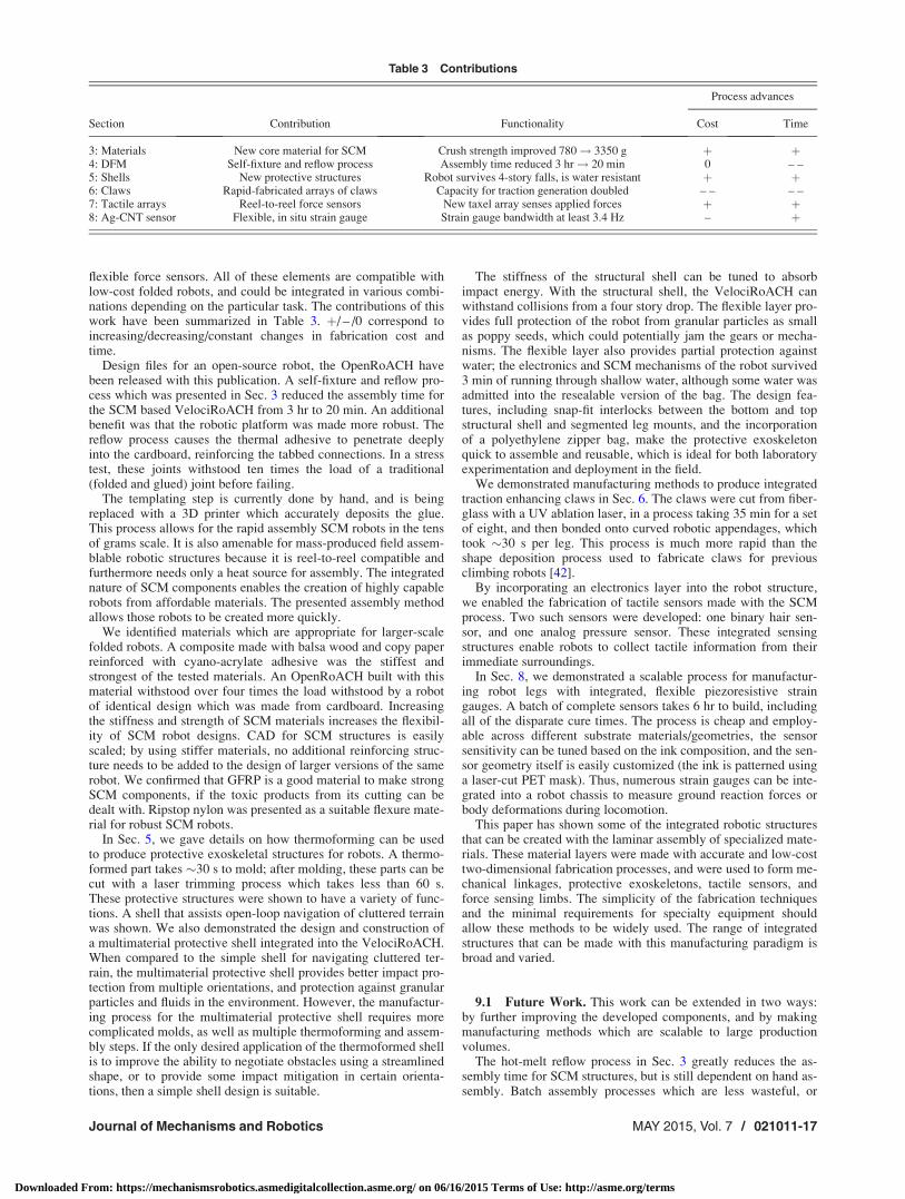
flexible force sensors. All of these elements are compatible withlow-cost folded robots, and could be integrated in various combi-nations depending on the particular task. The contributions of thiswork have been summarized in Table 3. þ/ – /0 correspond toincreasing/decreasing/constant changes in fabrication cost andtime.
Design files for an open-source robot, the OpenRoACH havebeen released with this publication. A self-fixture and reflow pro-cess which was presented in Sec. 3 reduced the assembly time forthe SCM based VelociRoACH from 3 hr to 20 min. An additionalbenefit was that the robotic platform was made more robust. Thereflow process causes the thermal adhesive to penetrate deeplyinto the cardboard, reinforcing the tabbed connections. In a stresstest, these joints withstood ten times the load of a traditional(folded and glued) joint before failing.
The templating step is currently done by hand, and is beingreplaced with a 3D printer which accurately deposits the glue.This process allows for the rapid assembly SCM robots in the tensof grams scale. It is also amenable for mass-produced field assem-blable robotic structures because it is reel-to-reel compatible andfurthermore needs only a heat source for assembly. The integratednature of SCM components enables the creation of highly capablerobots from affordable materials. The presented assembly methodallows those robots to be created more quickly.
We identified materials which are appropriate for larger-scalefolded robots. A composite made with balsa wood and copy paperreinforced with cyano-acrylate adhesive was the stiffest andstrongest of the tested materials. An OpenRoACH built with thismaterial withstood over four times the load withstood by a robotof identical design which was made from cardboard. Increasingthe stiffness and strength of SCM materials increases the flexibil-ity of SCM robot designs. CAD for SCM structures is easilyscaled; by using stiffer materials, no additional reinforcing struc-ture needs to be added to the design of larger versions of the samerobot. We confirmed that GFRP is a good material to make strongSCM components, if the toxic products from its cutting can bedealt with. Ripstop nylon was presented as a suitable flexure mate-rial for robust SCM robots.
In Sec. 5, we gave details on how thermoforming can be usedto produce protective exoskeletal structures for robots. A thermo-formed part takes �30 s to mold; after molding, these parts can becut with a laser trimming process which takes less than 60 s.These protective structures were shown to have a variety of func-tions. A shell that assists open-loop navigation of cluttered terrainwas shown. We also demonstrated the design and construction ofa multimaterial protective shell integrated into the VelociRoACH.When compared to the simple shell for navigating cluttered ter-rain, the multimaterial protective shell provides better impact pro-tection from multiple orientations, and protection against granularparticles and fluids in the environment. However, the manufactur-ing process for the multimaterial protective shell requires morecomplicated molds, as well as multiple thermoforming and assem-bly steps. If the only desired application of the thermoformed shellis to improve the ability to negotiate obstacles using a streamlinedshape, or to provide some impact mitigation in certain orienta-tions, then a simple shell design is suitable.
The stiffness of the structural shell can be tuned to absorbimpact energy. With the structural shell, the VelociRoACH canwithstand collisions from a four story drop. The flexible layer pro-vides full protection of the robot from granular particles as smallas poppy seeds, which could potentially jam the gears or mecha-nisms. The flexible layer also provides partial protection againstwater; the electronics and SCM mechanisms of the robot survived3 min of running through shallow water, although some water wasadmitted into the resealable version of the bag. The design fea-tures, including snap-fit interlocks between the bottom and topstructural shell and segmented leg mounts, and the incorporationof a polyethylene zipper bag, make the protective exoskeletonquick to assemble and reusable, which is ideal for both laboratoryexperimentation and deployment in the field.
We demonstrated manufacturing methods to produce integratedtraction enhancing claws in Sec. 6. The claws were cut from fiber-glass with a UV ablation laser, in a process taking 35 min for a setof eight, and then bonded onto curved robotic appendages, whichtook �30 s per leg. This process is much more rapid than theshape deposition process used to fabricate claws for previousclimbing robots [42].
By incorporating an electronics layer into the robot structure,we enabled the fabrication of tactile sensors made with the SCMprocess. Two such sensors were developed: one binary hair sen-sor, and one analog pressure sensor. These integrated sensingstructures enable robots to collect tactile information from theirimmediate surroundings.
In Sec. 8, we demonstrated a scalable process for manufactur-ing robot legs with integrated, flexible piezoresistive straingauges. A batch of complete sensors takes 6 hr to build, includingall of the disparate cure times. The process is cheap and employ-able across different substrate materials/geometries, the sensorsensitivity can be tuned based on the ink composition, and the sen-sor geometry itself is easily customized (the ink is patterned usinga laser-cut PET mask). Thus, numerous strain gauges can be inte-grated into a robot chassis to measure ground reaction forces orbody deformations during locomotion.
This paper has shown some of the integrated robotic structuresthat can be created with the laminar assembly of specialized mate-rials. These material layers were made with accurate and low-costtwo-dimensional fabrication processes, and were used to form me-chanical linkages, protective exoskeletons, tactile sensors, andforce sensing limbs. The simplicity of the fabrication techniquesand the minimal requirements for specialty equipment shouldallow these methods to be widely used. The range of integratedstructures that can be made with this manufacturing paradigm isbroad and varied.
9.1 Future Work. This work can be extended in two ways:by further improving the developed components, and by makingmanufacturing methods which are scalable to large productionvolumes.
The hot-melt reflow process in Sec. 3 greatly reduces the as-sembly time for SCM structures, but is still dependent on hand as-sembly. Batch assembly processes which are less wasteful, or
Table 3 Contributions
Process advances
Section Contribution Functionality Cost Time
3: Materials New core material for SCM Crush strength improved 780! 3350 g þ þ4: DFM Self-fixture and reflow process Assembly time reduced 3 hr! 20 min 0 – –5: Shells New protective structures Robot survives 4-story falls, is water resistant þ þ6: Claws Rapid-fabricated arrays of claws Capacity for traction generation doubled – – – –7: Tactile arrays Reel-to-reel force sensors New taxel array senses applied forces þ þ8: Ag-CNT sensor Flexible, in situ strain gauge Strain gauge bandwidth at least 3.4 Hz – þ
Journal of Mechanisms and Robotics MAY 2015, Vol. 7 / 021011-17
Downloaded From: https://mechanismsrobotics.asmedigitalcollection.asme.org/ on 06/16/2015 Terms of Use: http://asme.org/terms
more reliable than current techniques (Refs. [21] and [45], respec-tively) would further decrease the assembly time. Current SCMrobots are dependent on non reel-to-reel compatible componentssuch as the snap-close leg clips in Sec. 5.4. To a certain extentthis dependency will exist for any robot, because componentssuch as motors and batteries would be difficult to efficiently pro-duce in such a way. However, there would be fewer requiredmaterials and processes if more of a robot’s structure could bemade with a reel-to-reel compatible process, so it is a worthwhilepursuit for future work.
The protective structures would be improved with a fully water-proof, reclosable flexible shell layer that can resist punctures andtears from impacts and sharp objects. Investigating additionalenergy absorption components for the structural shell is also asubject of interest. The manufacturing methods used to producethe shells function better for low-volume prototyping methodsthan mass production. Fabrication techniques which incorporateprotective shells with reel-to-reel produced SCM mechanismswould facilitate the rapid manufacture of robust robotic structures.
Some of the manual steps used to fabricate the flexible forcesensors can be automated: painting of electrodes can be batchprocessed using a spray-painting technique to apply the CNT-AgNP ink to the legs. The other fabrication steps are alreadyconducive to batch-manufacture.
Acknowledgment
We would like to thank Shai Revzen for sharing his work onlarge-scale SCM robots. We would also like to thank KaushikJayaram for his insights on shells.
C.C. was responsible for the design, manufacturing, and charac-terization of the flexible and protective shells in Sec. 5. R.F.directed experiments and edited the paper. D.H. was responsiblefor Secs. 2–4. He designed the OpenRoACH robot which has beenopen-sourced with this publication, contributed to the research onclaws and the flexible shell, and was the editor of the paper. J.K.developed the force sensing arrays. J.L. was responsible forSec. 6. C.L. created the shell which enables the traversal of clut-tered terrain and identified relevant background research. A.P.assisted with shell manufacturing processes and mechanical design.E.S. was responsible for Sec. 8, with guidance and materials pro-vided by A.J. and H.O. D.Y. specified and performed the materialtests, and assembled the composite version of OpenRoACH.
This material is based upon work supported by the NationalScience Foundation under IGERT Grant No. DGE-0903711, theGraduate Research Fellowship Program, Grant No. CNS-0931463, the NSF NASCENT Center; also by the Miller Institutefor Basic Research in Science of UC Berkeley, the DARPA Maxi-mum Mobility and Manipulation program, and the United StatesArmy Research Laboratory under the Micro Autonomous Scienceand Technology Collaborative Technology Alliance.
References[1] Spagna, J. C., Goldman, D. I., Lin, P.-C., Koditschek, D. E., and Full, R. J.,
2007, “Distributed Mechanical Feedback in Arthropods and Robots SimplifiesControl of Rapid Running on Challenging Terrain,” Bioinspiration Biomimet-ics, 2(1), pp. 9–18.
[2] Li, C., Pullin, A. O., Haldane, D. W., Fearing, R. S., and Full, R. J., 2015,“Shape-Assisted Body Reorientation in Animals and Robots Enhances Traffic-ability Through Cluttered Terrain,” Bioinspiration Biomimetics (in press).
[3] Jayaram, K., Mongeau, J. M., McRae, B., and Full, R. J., 2010, “High-SpeedHorizontal to Vertical Transitions in Running Cockroaches Reveals a Principleof Robustness,” Annual Meeting, Society for Integrative and Comparative Biol-ogy, Seattle, WA, Jan. 3–7.
[4] Shimada, E., Thompson, J. A., Yan, J., Wood, R. J., and Fearing, R. S., 2000,“Prototyping Millirobots Using Dextrous Microassembly and Folding,” ASMEIMECE/DSCD, Orlando, FL, Nov. 5–10.
[5] Wood, R. J., Avadhanula, S., Menon, M., and Fearing, R., 2003, “MicroroboticsUsing Composite Materials: The Micromechanical Flying Insect Thorax,”IEEE International Conference on Robotics and Automation (ICRA ’03),Taipei, Taiwan, Sept. 14–19, pp. 1842–1849.
[6] Hoover, A. M., and Fearing, R. S., 2008, “Fast Scale Prototyping for FoldedMillirobots,” IEEE International Conference on Robotics and Automation(ICRA 2008), Pasadena, CA, May 19–23, pp. 886–892.
[7] Wood, R. J., Avadhanula, S., Sahai, R., Steltz, E., and Fearing, R. S., 2008,“Microrobot Design Using Fiber Reinforced Composites,” ASME J. Mech.Des., 130(5), p. 052304.
[8] Pullin, A., Kohut, N. J., Zarrouk, D., and Fearing, R. S., 2012, “Dynamic Turn-ing of 13 cm Robot Comparing Tail and Differential Drive,” IEEE InternationalConference on Robotics and Automation (ICRA), St. Paul, MN, May 14–18,pp. 5086–5093.
[9] Birkmeyer, P. M., Peterson, K., and Fearing, R. S., 2009, “DASH: A Dynamic16g Hexapedal Robot,” IEEE International Conference on Intelligent Robotsand Systems (IROS 2009), St. Louis, MO, Oct. 10–15, pp. 2683–2689.
[10] Hoover, A. M., Burden, S., Fu, X. Y., Sastry, S. S., and Fearing, R. S., 2010,“Bio-Inspired Design and Dynamic Maneuverability of a Minimally ActuatedSix-Legged Robot,” 3rd IEEE/RAS and EMBS International Conference onBiomedical Robotics and Biomechatronics (BioRob), Tokyo, Sept. 26–29, pp.869–876.
[11] Haldane, D. W., Peterson, K. C., Garcia Bermudez, F. L., and Fearing, R. S.,2013, “Animal-Inspired Design and Aerodynamic Stabilization of a HexapedalMillirobot,” IEEE International Conference on Robotics and Automation(ICRA), Karlsruhe, Germany, May 6–10, pp. 3279–3286.
[12] Haldane, D. W., and Fearing, R. S., 2014, “Roll Oscillation Modulated Turningin Dynamic Millirobots,” IEEE International Conference on Robotics and Auto-mation (ICRA), Hong Kong, May 31–June 7, pp. 4569–1575.
[13] Kohut, N. J., Peterson, K. C., Zarrouk, D., and Fearing, R. S., 2013,“Aerodynamic Steering of a 10 cm High-Speed Running Robot,” IEEE/RSJInternational Conference on Intelligent Robots and Systems (IROS), Tokyo,Nov. 3–7, pp. 5593–5599.
[14] Birkmeyer, P. M., Gillies, A. G., and Fearing, R. S., 2011, “CLASH: ClimbingVertical Loose Cloth,” 2011 IEEE/RSJ International Conference on IntelligentRobots and Systems (IROS), San Francisco, CA, Sept. 25–30, pp. 5087–5093.
[15] Birkmeyer, P., Gilles, A. G., and Fearing, R. S., 2012, “Dynamic Climbing ofNear-Vertical Smooth Surfaces,” IEEE/RSJ International Conference on Intelli-gent Robots and Systems (IROS), Vilamoura, Portugal, Oct. 7–12, pp.286–292.
[16] Boothroyd, G., Dewhurst, P., and Knight, A., 2002, Product Design for Manu-facture and Assembly, CRC Press, Boca Raton, FL.
[17] Hoover, A., and Fearing, R., 2009, “Analysis of Off-Axis Performance of Com-pliant Mechanisms With Applications to Mobile Millirobot Design,” IEEE/RSJInternational Conference on Intelligent Robots and Systems (IROS 2009), St.Louis, MO, Oct. 10–15, pp. 2770–2776.
[18] Ma, K. Y., Felton, S. M., and Wood, R. J., 2012, “Design, Fabrication, andModeling of the Split Actuator Microrobotic Bee,” IEEE/RSJ InternationalConference on Intelligent Robots and Systems (IROS), Vilamoura, Portugal,Oct. 7–12, pp. 1133–1140.
[19] Gu�erinot, A. E., Magleby, S. P., Howell, L. L., and Todd, R. H., 2005,“Compliant Joint Design Principles for High Compressive Load Situations,”ASME J. Mech. Des., 127(4), pp. 774–781.
[20] Whitney, J. P., Sreetharan, P. S., Ma, K. Y., and Wood, R. J., 2011, “Pop-UpBook MEMS,” J. Micromech. Microeng., 21(11), p. 115021.
[21] Sreetharan, P. S., Whitney, J. P., Strauss, M. D., and Wood, R. J., 2012,“Monolithic Fabrication of Millimeter-Scale Machines,” J. Micromech. Micro-eng., 22(5), p. 055027.
[22] Baisch, A. T., Ozcan, O., Goldberg, B., Ithier, D., and Wood, R. J., 2014, “HighSpeed Locomotion for a Quadrupedal Microrobot,” Int. J. Rob. Res. (in press).
[23] Sahai, R., Lee, J., and Fearing, R., 2003, “Semi-Automated Micro Assembly forRapid Prototyping of a One DOF Surgical Wrist,” IEEE/RSJ International Con-ference on Intelligent Robots and Systems (IROS 2003), Las Vegas, NV, Oct.27–31, pp. 1882–1888.
[24] Karrer, P., and Hofmann, A., 1929, “Polysaccharide XXXIX. €Uber den enzy-matischen Abbau von Chitin und Chitosan I,” Helv. Chim. Acta, 797(1925), pp.84–86.
[25] Hoffman, K. L., and Wood, R. J., 2011, “Passive Undulatory Gaits EnhanceWalking in a Myriapod Millirobot,” IEEE/RSJ International Conference onIntelligent Robots and Systems (IROS), San Francisco, CA, Sept. 25–30, pp.1479–1486.
[26] Mehta, A., and Rus, D., 2014, “An End-to-End System for Designing Mechani-cal Structures for Print-and-Fold Robots,” IEEE/RSJ International Conferenceon Robotics and Automation (ICRA), Hong Kong, May 31–June 7, pp.1460–1465.
[27] Soltero, D., Julian, B., Onal, C. D., and Rus, D., 2013, “A Lightweight Modular12-DOF Print-and-Fold Hexapod,” IEEE/RSJ International Conference onIntelligent Robots and Systems (IROS), Tokyo, Nov. 3–7, pp. 1465–1471.
[28] Hoover, A., Steltz, E., and Fearing, R., 2008, “RoACH: An Autonomous 2.4 gCrawling Hexapod Robot,” IEEE/RSJ International Conference on IntelligentRobots and Systems (IROS 2008), Nice, France, Sept. 22–26, pp. 26–33.
[29] Noh, M., Kim, S.-W., An, S., Koh, J.-S., and Cho, K.-J., 2012, “Flea-InspiredCatapult Mechanism for Miniature Jumping Robots,” IEEE Trans. Rob., 28(5),pp. 1007–1018.
[30] Hirata, K., 2000, “Development of Experimental Fish Robot,” Sixth Interna-tional Symposium on Marine Engineering (ISME 2000), Tokyo, Japan, Oct.23–27, pp. 235–240.
[31] Guo, S., Fukuda, T., and Asaka, K., 2003, “A New Type of Fish-Like Under-water Microrobot,” IEEE/ASME Trans. Mechatron., 8(1), pp. 136–141.
[32] Fish, F. E., Lauder, G. V., Mittal, R., Techet, A. H., Triantafyllou, M. S.,Walker, J. A., and Webb, P. W., 2003, “Conceptual Design for the Construction
021011-18 / Vol. 7, MAY 2015 Transactions of the ASME
Downloaded From: https://mechanismsrobotics.asmedigitalcollection.asme.org/ on 06/16/2015 Terms of Use: http://asme.org/terms

of a Biorobotic AUV Based on Biological Hydrodynamics,” 13th InternationalSymposium on Unmanned Untethered Submersible Technology, Durham, NH,Aug. 24–27.
[33] Lachat, D., Crespi, A., and Ijspeert, A. J., 2006, “Boxybot: A Swimming andCrawling Fish Robot Controlled by a Central Pattern Generator,” 1st IEEE/RAS-EMBS International Conference on Biomedical Robotics and Biomecha-tronics (BioRob 2006), Pisa, Italy, Feb. 20–22, pp. 643–648.
[34] Kovac, M., Schlegel, M., Zufferey, J.-C., and Floreano, D., 2010, “SteerableMiniature Jumping Robot,” Auton. Rob., 28(3), pp. 295–306.
[35] Floreano, D., Zufferey, J.-C., Klaptocz, A., Germann, J. M., and Kovac, M.,2011, “Aerial Locomotion in Cluttered Environments,” 15th International Sym-posium on Robotics Research, Flagstaff, AZ, Aug. 28–Sept. 1.
[36] Klaptocz, A., Briod, A., Daler, L., Zufferey, J.-C., and Floreano, D., 2013,“Euler Spring Collision Protection for Flying Robots,” IEEE/RSJ InternationalConference on Intelligent Robots and Systems (IROS), Tokyo, Japan, Nov.3–7, pp. 1886–1892.
[37] Karwoski, K., 2011, “Quadrocopter Control Design and Flight Operation,”NASA Marshall Space Flight Center, Huntsville, AL, Technical Report No.M11-0980.
[38] Wang, C., Nahon, M., and Trentini, M., 2014, “Controller Development andValidation for a Small Quadrotor With Compensation for Model Variation,”International Conference on Unmanned Aircraft Systems (ICUAS), Orlando,FL, May 27–30, pp. 902–909.
[39] O’Halloran, D., Wolf, A., and Choset, H., 2005, “Design of a High-Impact Sur-vivable Robot,” Mech. Mach. Theory, 40(12), pp. 1345–1366.
[40] Li, C., and Full, R. J., 2014, “Insects Traversing Grass-Like Vertical CompliantBeams,” Society for Integrative and Comparative Biology Annual Meeting,Austin, TX, Jan. 3–7.
[41] Autum, K., Buehler, M., Cutkosky, M. R., Fearing, R. S., Full, R. J., Goldman,D. I., Groff, R., Provancher, W., Rizzi, A. A., Saranli, U., Saunders, A., andKoditschek, D. E., 2005, “Robotics in Scansorial Environments,” Proc. SPIE,5804, pp. 291–302.
[42] Asbeck, A. T., Kim, S., Cutkosky, M. R., Provancher, W. R., and Lanzetta, M.,2006, “Scaling Hard Vertical Surfaces With Compliant Microspine Arrays,”Int. J. Rob. Res., 25(12), pp. 1165–1179.
[43] Karras, J. T., Haldane, D. W., and Fearing, R. S., 2012, “Rapid-ManufacturableHair Sensor Array for Legged Millirobots,” IEEE/RSJ International Con-ference on Intelligent Robots and Systems (IROS), Vilamoura, Portugal,Oct. 7–12, pp. 1956–1962.
[44] Takei, K., Yu, Z., Zheng, M., Ota, H., Takahashi, T., and Javey, A., 2014,“Highly Sensitive Electronic Whiskers Based on Patterned Carbon Nanotubeand Silver Nanoparticle Composite Films,” Proc. Natl. Acad. Sci. U.S.A.,111(5), pp. 1703–1707.
[45] Felton, S., Tolley, M., Demaine, E., Rus, D., and Wood, R., 2014, “AMethod for Building Self-Folding Machines,” Science, 345(6197), pp.644–646.
Journal of Mechanisms and Robotics MAY 2015, Vol. 7 / 021011-19
Downloaded From: https://mechanismsrobotics.asmedigitalcollection.asme.org/ on 06/16/2015 Terms of Use: http://asme.org/terms