integrated ocean drilling program expedition 307 ... · integrated ocean drilling program...
TRANSCRIPT
Integrated Ocean Drilling ProgramExpedition 307 Preliminary Report
Modern Carbonate Mounds: Porcupine Drilling
25 April–30 May 2005
Expedition Scientists

PUBLISHER’S NOTES
Material in this publication may be copied without restraint for library, abstract service, educational, or personal research purposes; however, this source should be appropriately acknowledged.
Citation: Expedition Scientists, 2005. Modern carbonate mounds: Porcupine drilling. IODP Prel. Rept., 307. doi:10.2204/iodp.pr.307.2005
Distribution: Electronic copies of this series may be obtained from the Integrated Ocean Drilling Program (IODP) Publication Services homepage on the World Wide Web at iodp.tamu.edu/publications.
This publication was prepared by the Integrated Ocean Drilling Program U.S. Implementing Organization (IODP-USIO): Joint Oceanographic Institutions, Inc., Lamont-Doherty Earth Observatory of Columbia University, and Texas A&M University, as an account of work performed under the international Integrated Ocean Drilling Program, which is managed by IODP Management International (IODP-MI), Inc. Funding for the program is provided by the following agencies:
European Consortium for Ocean Research Drilling (ECORD)
Ministry of Education, Culture, Sports, Science and Technology (MEXT) of Japan
Ministry of Science and Technology (MOST), People’s Republic of China
U.S. National Science Foundation (NSF)
DISCLAIMER
Any opinions, findings, and conclusions or recommendations expressed in this publication are those of the author(s) and do not necessarily reflect the views of the participating agencies, IODP Management International, Inc., Joint Oceanographic Institutions, Inc., Lamont-Doherty Earth Observatory of Columbia University, Texas A&M University, or Texas A&M Research Foundation.
August 2005

Expedition 307 Preliminary Report
The following scientists and personnel were aboard the JOIDES Resolution for Expedition 307 of the Integrated Ocean Drilling Program.
Expedition ScientistsTimothy FerdelmanCo-Chief ScientistDepartment of BiogeochemistryMax-Planck-Institute of Marine MicrobiologyCelsiusstrasse 128359 [email protected]: (49) 421-2028-651Fax: (49) 421-2028-690
Akihiro KanoCo-Chief ScientistDepartment of Earth and Planetary Systems ScienceGraduate School of ScienceHiroshima UniversityKagamiyama 1-3-1Higashi-hiroshima, [email protected]: (81) 82-424-6583Fax: (81) 82-424-0735
Trevor WilliamsStaff ScientistBorehole Research GroupLamont–Doherty Earth Observatory
of Columbia UniversityPO Box 1000, 61 Route 9WPalisades NY [email protected]: (914) 365-8626Fax: (914) 365-3182
Philippe GaillotLogging Staff ScientistCenter for Deep Earth Exploration (CDEX)Japan Agency of Marine-Earth Science
and TechnologyYokohama Institute for Earth Sciences3173-25 Showa-machi, Kanazawa-kuYokohama Kanagawa [email protected]: (81) 45-778-5818Fax: (81) 45-778-5704
Kohei AbePaleontologist (foraminifers)Graduate School of Life and Environmental
SciencesUniversity of Tsukuba1-1-1 TennodaiTsukuba [email protected]: (81) 29-853-4465Fax: (81) 29-851-9764
Miriam S. AndresSedimentologistRosenstiel School of Marine and Atmospheric
ScienceUniversity of Miami4600 Rickenbacker CausewayMiami FL [email protected]: (305) 421-4683Fax: (305) 421-4632
Morten BjeragerSedimentologistGeologisk InstitutUniversity of CopenhagenOster Voldgade 101350 [email protected]: (45) 3532 2401Fax: (45) 3314 8322
Emily L. BrowningPaleontologist (nannofossils)4019 Sumner StreetLincoln NE [email protected]: (251) 554-7756
3

Expedition 307 Preliminary Report
Barry A. CraggMicrobiologistDepartment of Earth SciencesCardiff UniversityMain Building, Park PlaceCardiff Wales CF10 3YEUnited [email protected]: (44) 29-2087-4928Fax: (44) 29-2087-4326
Ben De MolStratigraphic CorrelatorGRC Geociències MarinesUniversitat de BarcelonaCampus de Pedralbes08028 [email protected]: (34) 93 403 4641Fax: (34) 93 402 1340
Anneleen FoubertPaleomagnetistRenard Centre of Marine GeologyUniversiteit GentGeology and Soil SciencesKrijgslaan 281-S89000 [email protected]: (32) 9264 4591Fax: (32) 9264 4967
Tracy D. FrankInorganic GeochemistGeosciences DepartmentUniversity of Nebraska, Lincoln214 Bessey HallLincoln NE [email protected]: (402) 472-9799Fax: (402) 472-4917
Yuji FuwaPaleomagnetistDepartment of Earth SciencesToyama UniversityGofuju 3190Toyama [email protected]: (81) 076-445-6649Fax: (81) 076-445-6549
Jamshid J. GharibInorganic GeochemistDepartment of Geology and Geophysics/SOESTUniversity of Hawaii at Manoa1680 East West RoadHonolulu HI [email protected]: (808) 956-8558Fax: (808) 956-5512
Jay M. GreggSedimentologistGeological Sciences and EngineeringUniversity of Missouri-Rolla125 McNutt Hall1870 Miner CircleRolla MO [email protected]: (573) 241-4664Fax: (573) 341-6935
Veerle Ann Ida HuvenneStratigraphic CorrelatorChallenger Division for Seafloor ProcessesSouthampton Oceanography CentreWaterfront CampusEuropean WaySouthampton England SO14 3ZHUnited [email protected]: (44) 23 8059 6263Fax: (44) 23 8059 6554
Philippe LéonideOrganic GeochemistCentre de Sédimentologie-PaléontologieUniversité de ProvenceCNRS Research Unit FRE 27613 Place Victor Hugo, case 6713331 Marseille Cedex [email protected]: (33) 4 91 10 6208Fax: (33) 4 91 10 8523
4

Expedition 307 Preliminary Report
Xianghui LiSedimentologistDepartment of Earth SciencesChengdu University of TechnologyEr’xianqiao DongsanluChengdu Sichuan 610059Peoples Republic of [email protected]: (86) 28-84079527Fax: (86) 28-84075588
Kai MangelsdorfMicrobiologist/GeochemistOrganic Geochemistry and Hydrocarbon SystemsGeo Forschungs Zentrum PotsdamDepartment 4.3, Telegrafenberg B42314473 [email protected]: (49) 331-288-1785Fax: (49) 331-288-1782
Akiko TanakaPhysical Properties SpecialistInstitute of Geology and GeoinformationGeological Survey of Japan, AISTTsukuba Central 71-1-1 HigashiTsukuba Ibaraki [email protected]: (81) 29-861-3962Fax: (81) 29-861-3609
Ivana NovoselSedimentologistDepartment of Earth SciencesRice University6100 Main Street, MS-126Houston TX [email protected]: (713) 348-5135Fax: (713) 348-5214
Saburo SakaiInorganic GeochemistInstitute for Frontier Research on Earth Evolution
(IFREE)Japan Agency of Marine-Earth Science
and Technology2-15 Natsushima-choYokosuka [email protected]: (81) 46-867-9784
Fax: (81) 46-867-9775
Vladimir A. SamarkinMicrobiologistDepartment of Marine SciencesUniversity of Georgia220 Marine Sciences BuildingAthens GA [email protected]: (706) 353-0593Fax: (706) 542-5888
Keiichi SasakiSedimentologistDepartment of Cultural Properties and HeritagesKanazawa Gakuin University10 Sue-machiKanazawa Ishikawa [email protected]: (81) 76-229-8859Fax: (81) 76-229-8718
Arthur J. SpivackMicrobiologist/GeochemistGraduate School of OceanographyUniversity of Rhode IslandMarine GeologyBay Campus, South Ferry RoadNarragansett RI [email protected]: (401) 874-6200Fax: (401) 874-6811
Chizuru TakashimaSedimentologistEarth and Planetary Systems ScienceHiroshima UniversityKagamiyama 1-3-1Higashi Hiroshima [email protected]: (81) 824-24-6583Fax: (81) 824-24-0735
Jürgen TitschackSedimentologistInstitut für PaläontologieUniversität Erlangen-NürnbergLoewenichstrasse 2891054 [email protected]: (49) 131-852-4756Fax: (49) 131-852-2690
5

Expedition 307 Preliminary Report
ObserversBoris DorschelDepartment of GeologyUniversity College CorkDonovan’s [email protected]
Xavier MonteysMarine DepartmentGeological Survey of IrelandBeggars Bush, Haddington RoadDublin [email protected]: (353) 1604 1466Fax: (353) 1604 1436
Transocean OfficialsAlexander SimpsonMaster of the Drilling VesselOverseas Drilling Ltd.707 Texas Avenue South, Suite 213DCollege Station TX 77840-1917USA
Wayne MaloneDrilling SuperintendentOverseas Drilling Ltd.707 Texas Avenue South, Suite 213DCollege Station TX 77840-1917USA
IODP Shipboard Personnel and Technical RepresentativesAndy BakerMarine Laboratory Specialist: Downhole Tools/
Thin Sections
Bill CrawfordImaging Specialist
Lisa K. CrowderAssistant Laboratory Officer
Klayton CurtisMarine Laboratory Specialist: Paleomagnetism
Roy T. DavisLaboratory Officer
Javier EspinosaSchlumberger Engineer
David FacklerApplications Developer
Kazuho FujineMarine Laboratory Specialist: Core
Dennis GrahamMarine Laboratory Specialist: Chemistry
Margaret HastedtMarine Computer Specialist
Kristin HillisYeoperson
Denise HudsonLaboratory Specialist: Underway Geophysics
Eric JacksonMarine Laboratory Specialist: X-Ray
Jan Jurie KotzeMarine Instrumentation Specialist
David MorleyMarine Computer Specialist
Chieh PengAssistant Laboratory Officer
Pieter PretoriusMarine Instrumentation Specialist
Derryl SchroederOperations Superintendent
Paula WeissMarine Curatorial Specialist
Brad WeymerMarine Laboratory Specialist: Physical Properties
Robert M. WheatleyLaboratory Specialist: Chemistry
6

Expedition 307 Preliminary Report
ABSTRACT
Challenger Mound, a putative carbonate mound structure covered with dead deepwa-ter coral rubble and located in Porcupine Seabight on the southwest Irish continentalmargin, was the focal point of twelve days of scientific drilling aboard the JOIDES Res-olution during Integrated Ocean Drilling Program Expedition 307.
Specific drilling objectives included the following:
1. Establish whether the mound base rested on a carbonate hardground of microbialorigin and whether past geofluid migration events acted as a prime trigger formound genesis.
2. Define the relationship, if any, between mound initiation, mound growth phases,and global oceanographic events.
3. Analyze geochemical and microbiological profiles that define the sequence of mi-crobial communities and geomicrobial reactions throughout the drilled sections.
4. Examine high-resolution paleoclimatic records from the mound section using awide range of geochemical and isotopic proxies.
5. Describe the stratigraphic, lithologic, and diagenetic characteristics, includingtiming of key mound-building phases, for establishing a depositional model ofdeepwater carbonate mounds and for investigating how they resemble ancientmud mounds.
In addition to the mound, one site immediately downslope of Challenger Mound andan upslope site were drilled to (1) constrain the stratigraphic framework of the slope/mound system, (2) identify and correlate erosional surfaces observed in slope sedi-ment seismics, and (3) investigate potential gas accumulation in the sediments un-derlying the mound.
Drilling revealed that the mound rests on a sharp erosion boundary. Sediments belowthis erosion surface consist of glauconitic and silty sandstone drift deposits of middleMiocene age that grade upward toward more clay rich intervals. The latter are tenta-tively interpreted to represent relatively low energy environments in the late Mio-cene–Pliocene succession. The Pliocene strata end abruptly in a firmground that isoverlain by the Pleistocene mound succession. Biostratigraphic results suggest thatthe hiatus between the two successions spans at least 1.65 m.y. The mound flanks aredraped by late Pleistocene (<0.26 Ma) silty clay deposits that frequently contain drop-stones.
7
Expedition 307 Preliminary Report
The mound succession just above the firmground is represented by interbeddedgrainstone, floatstone, rudstone, packstone, and wackestone in decimeter thick-nesses, all reflecting relatively rapidly changing depositional realms. Above this lowerlevel, the mound succession shows pronounced recurring cycles of Pleistocene coralfloatstone, rudstone, wackestone, and packstone on a several meter scale that are wellrepresented in the carbonate content change and are most probably associated withPleistocene glacial–interglacial cycles. A role for hydrocarbon fluid flow in the initialgrowth phase of Challenger Mound is not obvious either from the lithostratigraphyor from initial geochemistry and microbiology results. We found no significant quan-tities of gas in the mound or in the subbasal mound sediments, nor were carbonatehardgrounds observed at the mound base.
Microbial effects on mound and submound diagenesis are more subtle. We detectedthe methane–sulfate transition only in the deeper-lying Miocene silt and sandstonesunderlying the mound, where methane concentrations and prokaryotic cell abun-dances increase with increasing depth. In the mound itself, interstitial water profilesof sulfate, alkalinity, Mg, and Sr suggest a tight coupling between carbonate diagene-sis and microbial sulfate reduction. Decomposition of organic matter (organoclastic)by sulfate reduction may drive the biogeochemical processes of mineralogical trans-formation by (1) producing CO2, which enhances aragonite dissolution and (2) in-creasing overall dissolved inorganic carbon concentration, which allows dolomite orhigh-Mg calcite to precipitate. Furthermore, periods of rapid sedimentation overlyinghiatuses apparently left distinct signals in the interstitial water chemistry of the Pleis-tocene sediments that surround and partially bury the carbonate mounds of Porcu-pine Seabight.
INTRODUCTION
Carbonate mounds and reefs are a fundamental and recurrent expression of life in thegeological record from Precambrian times onward. The true dawn of carbonate mudmounds is in Cambrian times, when mounds suddenly featured a diversity in micro-bial and biodetrital fabrics with abundant mound-building calcified microbes(Riding, 1991), calcareous algae, and a variety of Paleozoic benthic invertebrates thatmay have played an ancillary role in mound construction. In mid- to late Ordoviciantimes, the dramatic rise of large skeletal metazoans such as stromatoporoids, corals(Rugosa and Tabulata), and bryozoans, as well as higher algae, paved the way for thestrong development of reefs and typical stromatactoid mud mounds. Lower Devo-
8

Expedition 307 Preliminary Report
nian (Gedinnian) mounds in the Montagne Noire, France, exhibit the most spectac-ular stromatactis fabrics, interpreted as the result of decaying microbial mats (Flajsand Hüssner, 1993). Stratigraphically younger (Emsian) conical carbonate mounds(kess-kess) of the Moroccan Anti-Atlas are related to precipitation from hydrothermalfluids (Kaufmann, 1997), some of which are inferred to be related to a light carbonsource (hydrocarbon). Some of the most impressive of early Carboniferous bank ag-gregates, as thick as 1 km, are those known as the Waulsortian reefs (Lees, 1988; Som-erville, 2003). In full Mesozoic times, declines in the abundance and diversity ofmicrobial mounds are recorded from the Triassic to the Cretaceous. From the mid-Cretaceous onward, microbial fabrics are only known as components to metazoanframework reefs (Riding, 1991). Most Cenozoic mud mounds are of biodetrital origin,although microbial components might have remained significant in deeper water.Scientific drilling (Ocean Drilling Program [ODP] Leg 182) confirmed the existence ofbryozoan reef mounds buried in the cold-water carbonate platform sediments at 200–350 meters below sea level (mbsl) in Great Australian Bight (Feary et al., 1999; Jameset al., 2000). These mound complexes consist of unlithified floatstone structures, richin zooidal bryozoan forms that were still growing during the last glacial lowstand.
Coral reefs are commonly considered to have developed in shallow-water tropical tosubtropical regions with typical carbonate depositional environments. However, thediscovery of large-scale deepwater carbonate mounds extending along the northeast-ern Atlantic continental margins as well as the Australian bryozoan reef mounds incool-water slope environments has cast new interest on their structure, origin, anddevelopment. The Atlantic coral mounds from depths where light cannot reach werefirst described by Neuman et al. (1977). They discovered that benthic invertebrates in-cluding corals and crinoids construct mounds several hundred meters wide and 50 mhigh at 600–700 mbsl along the Straits of Florida west of the Bahamas. They were con-sidered to be an exceptional case of coral reefs developed in amazingly deep environ-ments, but contemporaneously similar structures had been recognized in numerousoil industry seismic profiles collected from the northeast Atlantic. Scientific researchon deepwater coral mounds was stimulated by the release of some of these profiles inthe mid-1990s. Oceanographic exploration using side-scan sonar, underwater videoimagery, and drag sampling has collected information on bottom sediments and in-dicated that the structures are really formed by benthic communities with cold-watercorals. Currently, the deepwater coral banks and mounds are known to occur atdepths to 1500 m on shelves, shelf margins, and seamounts of the northeast Atlanticfrom Morocco to Arctic Norway. Additional high-resolution seismic surveys revealedthat the mound structures can reach a width of several kilometers (Freiwald et al.,
9
Expedition 307 Preliminary Report
2004) and a height of 350 m (Kenyon et al., 2003). Exploration for deepwater coralbanks was recently expanded outside of Atlantic areas and showed their possible glo-bal distribution.
Among the deepwater mound provinces, the most intensively studied provinces areoffshore of Norway, Rockall Trough, and Porcupine Seabight located southwest of Ire-land. Along the Norwegian continental slope extending from 62°–70°N, cold-watercorals form banks or mounds up to 40 m high at 400–500 mbsl. They appear to de-velop on stable substrate formed of the exposed Neogene sedimentary rock and boul-ders derived from fjords (Freiwald et al., 1997).
The Porcupine Seabight area surpasses the Norwegian offshore area in terms of sizeand frequency of the mounds and is the most important Atlantic mound area. Seismicstudies have revealed more than 1500 carbonate mounds in the Magellan moundprovince, and it is estimated that there are ~2000 mounds in Porcupine Basin (De Molet al., 2002; Huvenne et al., 2003) that generally exhibit conical geometries sur-rounded or covered by siliciclastic contourites. They can reach as high as 250 m andas wide as 5 km (Huvenne et al., 2002, 2003; De Mol et al., 2002). The mounds in Por-cupine Seabight have been the focus of more than 20 cruises in the last decade. Sedi-ments and video images collected on the seafloor indicate that the mounds arecommonly colonized by various biota including deep-sea corals Lophelia and Ma-drepora and other invertebrates (Foubert el al., 2005). However, details on the internalstructure, initiation, and growth of these impressive seafloor features within Porcu-pine Seabight remained veiled. Explanations of the origin and evolution of the Por-cupine mounds revolve around two scenarios that may be expressed as eithercompeting or complementary hypotheses: (1) oceanographic and paleoenviron-mental conditions control mound initiation and growth, and (2) hydrocarbon seep-age initiates microbial-induced carbonate formation and indirectly fuels coral growth(endogenous control) (Hovland et al., 1998; Henriet et al., 2001). The oceanographicor environmental hypothesis states that the most important conditions stimulatingmound development are the interaction of water currents and sediment dynamics.Enhanced currents provide nutrient for the corals and may sweep free stable sub-strates for settlement of coral larvae (Frederiksen et al., 1992; De Mol et al., 2002 [Por-cupine]; Kenyon et al., 2003 [Rockall]; Freiwald et al. 1997 [Norway]; Colman et al.,2005 [Mauritania]). Enhanced bottom currents at tidal frequency (Pingree and LeCann, 1989, 1990) are observed in the Porcupine mound provinces (Rice et al., 1991).They may result from the internal tides at the boundary between water masses of dif-ferent densities, such as between Mediterranean Outflow Water (MOW) and Eastern
10

Expedition 307 Preliminary Report
North Atlantic Water (ENAW), located at ~800 meters below seafloor (mbsf) at present(White, 2001). A strong current provides suspended food to filter-feeding cold-watercorals, sweeps the polyps clean of detritus, and protects the corals from sedimentburial. Initiation of mound development has been linked to global paleoceano-graphic change. Closure of the Isthmus of Panama at ~4.6 Ma deviated the hugewarm-water mass of ENAW and increased deepwater advection and stratification inthe Atlantic (Haug and Tiedemann, 1998). In combination, MOW resumed after thelate Miocene–Early Pliocene salinity crisis in the Mediterranean (Maldonado and Nel-son, 1999). The oldest fossil records of Lophelia and Madrepora were reported from theMediterranean area in the Early Pliocene. Initiation of the deep-sea coral moundsmight have been related to establishment of MOW and/or ENAW, which introducedlarvae of the cold-water corals to the northeast Atlantic in a manner similar to thecoral banks established on the Nordic continental shelf break (Henriet et al., 1998).
The seepage hypothesis was first proposed by Hovland et al. (1994), who correlatedthe distribution between coral mounds with areas showing high dissolved light hy-drocarbon contents in water. Hydrocarbon seepage may prepare favorable conditionsfor deep-sea corals, in terms of raised inorganic carbon for skeletal accretion (Hovlandet al., 1998) and for submarine lithification providing stable substrate. The aligned oc-currence seen in some mounds of Porcupine Seabight suggests that the mounds wereestablished along linear structures, such as faults (Hovland et al., 1994). Bailey et al.(2003), however, studied the Magellan mound province in detail from two-dimen-sional and three-dimensional (3-D) seismic data and found no correlation betweenmounds and fault locations. Henriet et al. (1998) suggested that conditions in the Ma-gellan province during glacial periods were probably suitable for gas hydrate forma-tion and that decomposition of the gas hydrate could trigger a submarine slide. Laterphases of gas seepage would then be focused by this buried slide to specific locations,causing the ringlike structure in the Magellan mounds. The oceanographic and fluidseepage scenarios may have acted in a complementary fashion: microbially inducedcarbonate hardground formation associated with gas or hydrocarbon seepage pro-vided the hard substrate required by the settling coral larvae. Once established, fur-ther development of the mound was subject to oceanographic conditions suitable forfurther coral growth. The presence of corals covering the mound may be only fortu-itous. The mounds themselves may be composed of microbial automicrite, like well-known Phanerozoic carbonate mounds, but only recently covered by cold-water cor-als. Coral growth might even have led to accelerated burial of the mound structuresthrough enhanced baffling and trapping of sediment. Conclusive evidence for any ofthese theories is still missing. Only scientific drilling through the core of a mound
11

Expedition 307 Preliminary Report
structure will provide clearer insight to the formation and development of these enig-matic structures. Integrated Ocean Drilling Program (IODP) Expedition 307 was pro-posed to obtain evidence for understanding the origin and evolution of the deepwatercarbonate mounds in Porcupine Seabight. Sedimentary processes and paleoclimatichistory are recorded in lithostratigraphic, biostratigraphic, magnetostratigraphic, andphysical property data. In addition, the mounds may be biological constructions as-sociated with hydrocarbon-rich fluids and therefore provide a unique habitat for thedeep biosphere. Geochemical and microbiological profiles would define the sequenceof microbial communities and geomicrobial reaction throughout the drilled sectionsand provide basic information to understand diagenetic processes within themounds.
The Atlantic deep-sea carbonate mounds share geometric features and occurrenceswith numerous Phanerozoic mud mounds of different ages formed under the controlof microbial processes. Perhaps the Porcupine mounds are present-day analogs for thePhanerozoic reef mounds and mud mounds, for which depositional processes and en-vironmental settings are not fully understood. Or are these mounds North Atlanticequivalents to the Quarternary bryozoan mounds found in Great Australian Bight?Limestone bodies that contain coral skeletons are usually interpreted as indicatingwarm and shallow water; however, the abundance of deepwater coral mounds meansuch paleoenvironmental interpretation may not be so simple.
Deepwater coral mounds may also be potential high-resolution environmental re-corders. Mound section lithology and bioclastic composition might record glacial–interglacial climate changes because cold-water corals are sensitive to conditions suchas water temperature and current strength. Furthermore, coral skeletons themselvescan be used for analysis: 14C and Cd content were used to reconstruct changes indeep-sea circulation (Frank et al., 2004) and nutrient contents (Adkins et al., 1998),respectively. Cold-water corals grow as fast as 25 mm/y (Rogers, 1999), fast enough toapply the same methods of the coral climatology using tropical–subtropical reef-forming corals. Analyses of stable isotopes and trace elements are expected to providetemperature and carbon circulation data at a subannual resolution.
12

Expedition 307 Preliminary Report
BACKGROUND
Overview of Porcupine Seabight Mounds
A geographic overview of Porcupine Seabight and the mound provinces is shown onFigure F1. Three different types of mound provinces were identified: the Hovland,Magellan, and Belgica mounds.
Hovland Mounds
The first mound occurrences reported from industrial data on the northern slope ofPorcupine Basin (Hovland et al., 1994) led to the unveiling of a complex setting withlarge multiphased contourite deposits and high-energy sediment fills, topped by a setof outcropping mounds or elongated mound clusters as high as 250 m (Henriet et al.,1998; De Mol et al., 2002).
Magellan Mounds
The Hovland mounds are flanked to the north and west by the crescent-shaped, well-delineated Magellan mound province with a very high density of buried medium-sized mounds (1 mound/km2; average height = 60–80 m). High-resolution seismicdata (Henriet et al., 2001) combined with 3-D industrial seismic data (Huvenne et al.,2003) shed light on the presence of a past slope failure that underlies most of themound cluster.
Belgica Mounds
On the eastern margin of Porcupine Basin, a 45 km long range of large mounds towersfrom a strongly erosional surface (Fig. F1). The mounds partly root on an enigmatic,deeply incised, very faintly stratified seismic facies (Unit P2) (De Mol et al., 2002; VanRooij et al., 2003). De Mol et al. (2002) interpreted this seismic facies as a nannofossilooze of Pliocene age analogous to the similar seismic facies of ODP Site 980 in thesouthwestern Rockall Trough (Jansen, Raymo, Blum, et al., 1996) and partly on a lay-ered sequence capped by a surprising set of short-wavelength, sigmoidal depositionalunits (De Mol et al., 2002; Van Rooij et al., 2003).
The Belgica mound province consists of 66 conical mounds (single or in elongatedclusters) in water depths ranging from 550 to 1025 m. The mounds are partly en-closed in an impressive set of contourites (Van Rooij et al., 2003). Mounds typicallytrap sediment on their upslope flank, which is consequently buried, whereas their
13

Expedition 307 Preliminary Report
seaward side is well exposed and forms a steep step in bathymetry. Average slopes are10°–15°. The largest mounds have a height of ~170 m. In the deeper part of the Belgicamound province (Beyer et al., 2003), an extremely “lively” mound was discovered in1998 on the basis of a very diffuse surface acoustic response. This mound, known asThérèse Mound, was selected as a special target site to study processes involved inmound development for European Union (EU) Fifth Framework research projects.Video imaging revealed that Thérèse Mound, jointly with its closest neighbor, GalwayMound, might be one of the richest deepwater coral environments in PorcupineSeabight, remarkably in the middle of otherwise barren mounds (Galanes-Alvarez,2001; Foubert et al., 2005, De Mol et al., in press).
Geological Setting
Porcupine Seabight forms an inverted triangle opening to the Porcupine Abyssal Plainthrough a narrow gap of 50 km at a water depth of 2000 m at its southwest apex be-tween the southern and western tips of the Porcupine Bank and terraced Goban Spur,respectively. Porcupine Seabight gradually widens and shoals to depths of 500 m tothe east on the Irish continental shelf and north to Slyne Ridge. Porcupine Seabight,which is the surface expression of the underlying deep sedimentary Porcupine Basin(Fig. F2), is a failed rift of the proto-North Atlantic Ocean and is filled with a 10 kmthick series of Mesozoic and Cenozoic sediments (Shannon, 1991). Basin evolutioncan be summarized in three major steps: a Paleozoic synrift phase, a predominantlyJurassic rifting episode, and a Late Cretaceous–Holocene thermal subsidence period.
Basin Development and Synrift Sedimentation
The basement of Porcupine Basin is composed of Precambrian and lower Paleozoicmetamorphic rocks forming continental crust ~30 km thick (Johnston et al., 2001).The prerift succession commences with probably Devonian clastic sediments overlainby lower Carboniferous carbonates and clastics. The upper Carboniferous rocks fea-ture deltaic to shallow-marine deposits with Westphalian coal-bearing sandstonesand shales and possibly Stephanian redbed sandstones (Shannon, 1991; Moore andShannon, 1995). The lowermost Mesozoic deposits are early rift valley continentalsediments which can be >2 km thick. During Permian times, predominantly fluvialand lacustrine sedimentation took place with nonmarine mixed clastic deposits andevaporites. Triassic sediments contain nonmarine to marine facies (Ziegler, 1982;Shannon, 1991). Lower Jurassic deposits are not found over the entire basin but couldcomprise limestones and rare organic-rich shales with sandstones.
14

Expedition 307 Preliminary Report
Jurassic Rifting Phase
The middle Kimmerian rifting phase marked an increase in tectonic events in the Arc-tic, Atlantic, and Thetys rift systems. This major tectonic event was apparently accom-panied by a renewed eustatic lowering of sea level and is likely responsible for erosionof a large part of the Triassic and Jurassic deposits (Ziegler, 1982). Middle Jurassic flu-vial claystones and minor sandstones might lie unconformably above earlier depos-ited strata and can be considered to be products of this major rifting episode. Duringthe Late Jurassic, differential subsidence was responsible for the transition from a con-tinental to a shallow-marine sedimentary environment in Porcupine Basin.
Postrift Thermal Subsidence
At the start of the Cretaceous, the general structure of Porcupine Basin could be com-pared with a rift structure prior to breakup; its specific failed rift structure has a typicalsteer’s head profile (Moore and Shannon, 1991). A major rifting pulse during the EarlyCretaceous, referred to as late Kimmerian tectonics, was accompanied by a significanteustatic sea level fall and gave rise to a regional unconformity that is largely of sub-marine nature (Ziegler, 1982; Moore and Shannon, 1995). This undulatory unconfor-mity marks the base of the Cretaceous, where marine strata onlap Jurassic sequences(Shannon, 1991). The onset of the Upper Cretaceous was characterized by a furtherrelative sea level rise, featuring offshore sandstone bars, followed by a northwardthinning and onlapping outer shelf to slope sequence of carbonates (chalk). Alongthe southwestern and southeastern margins of the basin, Moore and Shannon (1995)recognized the presence of biohermal reef buildups. The transition from LateCretaceous to early Paleocene sedimentation is characterized by a high-amplitudeseismic reflector marking the change from carbonate to clastic deposition (Shannon,1991). Most of the Paleogene postrift sediments are dominantly sandstones andshales, influenced by frequent sea level fluctuations. In general, the Paleocene succes-sion is more mud-dominated, whereas the main coarse clastic input occurred in themiddle Eocene to earliest late Eocene (McDonnell and Shannon, 2001). The Paleo-cene–Eocene is subdivided into five sequences characterized by southerly progradingcomplex deltaic events overlain by marine transgressive deposits (Naylor and Shan-non, 1982; Moore and Shannon, 1995). The controls on the relative rises and falls insea level are dominantly due to the North Atlantic plate tectonic regime. During thelate Paleogene and Neogene, passive uplift of the Norwegian, British, and Irish land-masses was very important in shaping the present-day Atlantic margin. Although theorigin of this uplift remains unclear, it probably resulted in enhancement of contour
15

Expedition 307 Preliminary Report
currents, causing local erosion and deposition and an increased probability of sedi-mentary slides and slumps. Therefore, overall Oligocene and Neogene sedimentationis characterized by along-slope transport and redepositional processes yielding con-tourite siltstones and mudstones and hemipelagic–pelagic deep-marine sediments,caused by a combination of differential basin subsidence and regional sea level andpaleoclimate changes. The youngest unconformity mapped in Porcupine Basin is cor-related with an Early Pliocene erosion event in Rockall Basin and is considered to bea nucleation site for present-day coral mounds (McDonnell and Shannon, 2001; DeMol et al., 2002; Van Rooij et al., 2003).
Pleistocene and Holocene Sedimentation
Recent sedimentation is mainly pelagic to hemipelagic, although foraminiferal sands(probably reworked) can be found on the upper slope of the eastern continental mar-gin. The main sediment supply zone is probably located on the Irish and Celticshelves, whereas input from Porcupine Bank seems to be rather limited (Rice et al.,1991). In contrast to the slopes of the Celtic and Armorican margins, which are char-acterized by a multitude of canyons and deep-sea fans, the east-west-oriented Gollumchannels are the only major downslope sediment transfer system located on thesoutheastern margin of the seabight (Kenyon et al., 1978; Tudhope and Scoffin,1995), which discharges directly onto the Porcupine Abyssal Plain. Rice et al. (1991)suggest that the present-day channels are inactive. According to Games (2001), theupper slope of northern Porcupine Seabight bears predominantly north-south-trend-ing plough marks on several levels within the Quaternary sedimentary succession.Smaller plough marks are also observed and interpreted as Quaternary abrasion of thecontinental shelf caused by floating ice grounding on the seabed. An abundance ofpockmarks is also apparent on the seabed in this area. Within some of these Conne-mara pockmarks, an associated fauna of the cold-water coral Lophelia pertusa has beensuggested (Games, 2001). Together with Madrepora oculata, L. pertusa is found alongthe entire northwest European margin, manifest as coral patches to giant coral banks.
Seismic Studies/Site Survey Data
Studies carried out during the past 7 y under various EU Fourth and Fifth Frameworkprograms, European Science Foundation programs, and various European nationalprograms have gathered substantial information from the area of interest, includingbox cores, long gravity cores, piston cores, high-resolution seismics (surface and deeptowed), side-scan sonar at various frequencies and elevations over the seabed, surface
16

Expedition 307 Preliminary Report
multibeam coverage, and ultra-high-resolution swath bathymetry (using a remotelyoperated vehicle [ROV]) and video mosaicing (using ROV). High-resolution seismicdata (penetration = ~350 m; resolution = 1–3 m) have been acquired over the Belgicamound province (1125 km of seismic lines over a 1666 km2 area). All drill sites wereprepared by a minimum of a set of high-quality cross lines. Side-scan sonar data havebeen acquired at various resolutions and elevations: deep-tow 100 kHz side-scan so-nar and 3.5 kHz profiler, resolution = 0.4 m (95 km2 in the Belgica mound province),high-resolution Makanchi acoustic imaging data (Training Through Research Pro-gram), and towed ocean bottom instrument side-scan sonar (30 kHz). A multibeamsurvey was completed in June 2000 (Polarstern), and the area was covered again by theIrish Seabed Program. The ROV VICTOR (Institut Francais de Recherche pour l’Explo-ration de la Mer) was employed twice (Atalante and Polarstern) to video survey bothThérèse and Challenger Mounds. Previous subbottom sampling includes more than40 gravity and piston cores in the Belgica mound province (penetration = 1.5–29 m),numerous box cores, and some television-controlled grab samples of ~1.5 ton.
Recent very high resolution seismic investigations (Belgica) identified three seismicunits (P1–P3) and provide an intriguing picture of the main possible sedimentary fa-cies forming and underlying the mound (Fig. F3). Seismic imaging suggests that Chal-lenger Mound roots on the sharp slope break off of seismic Unit P1 with an erosionalupper boundary (Fig. F4). One interpretation of this seismic data, tested during Expe-dition 307, is the need to introduce a slightly higher velocity (2000 m/s) in themound core seismic model. This suggests the beginning of lithification (Henriet et al.,2002). The uppermost seismic unit (P3) at Site U1318 is thought to represent late Neo-gene drift deposits (Van Rooij et al., 2003). Unit P3 partly overlies a seismic facies withlow-amplitude reflectors and an unknown lithology (Unit P2) that underlies thesouthern part of the Belgica mound province but disappears below ChallengerMound (Sites U1316 and U1317). The uppermost surface of Unit P2 also appears tobe an erosional surface (De Mol et al., 2002). Below this erosional surface, seismic UnitP1 contains a parallel series of high-amplitude reflectors that dip toward PorcupineBasin. Unit P1 has characteristic wave-shaped reflectors within its upper strata. Thesesigmoid-shaped waveforms enclose small lenticular bodies, frequently characterizedby a high-amplitude roof, which also appear at the root of Challenger Mound and arethought to be of Miocene age (Van Rooij et al., 2003). They appear to reflect high-energy slope deposits and have the possibility, based on reversals of signal polarity, tocontain traces of gas. An alternative explanation for the phenomenon is a contrast inlithology between the top of the sigmoidal bodies and the overlying sediments incombination with the geometry of the unit, which enhanced the amplitude of the re-
17

Expedition 307 Preliminary Report
flection. The top reflectors of this unit might consist of more compact sediments or adiagenetic cap creating the observed higher amplitudes (De Mol et al., in press).
SCIENTIFIC OBJECTIVES
External versus Internal Controls
The apparent coincidence between the presence of giant mound clusters and poten-tially deeper-lying hydrocarbon deposits suggests a possible internal control frommostly transient fluxes of geofluids in deep geological reservoirs to the seabed (Fig.F2). Two-dimensional basin modeling has been used to evaluate the possible link be-tween hydrocarbon leakage and mound growth (Naeth et al., 2005). Seismic lines ofindustrial origin and six exploration wells were used to calibrate the burial and ther-mal history using vitrinite reflectance, bottom hole temperatures, and apatite fissiontrack data. Modeling results indicate that Jurassic and older source rocks are matureto overmature throughout the basin. Cretaceous strata are immature to mature in thecentral part of the basin and immature on the flanks. The Tertiary sequence remainsimmature over the entire basin. Hydrocarbon generation started in Late Cretaceoustimes for the deepest sequences. Phase separation was modeled to occur during mi-gration at depth ranges between 2000 and 4000 m. Upon phase separation, migrationof free gas phase dominated over that of oil, such that gas is the main migrating fluidin shallower intervals. Migration is mainly buoyancy-driven and vertical. Only Ap-tian and Tertiary deltaic layers direct hydrocarbon flow out of the basin. The modelpredicts a potential focusing of gas migration toward the Belgica mounds area, wherea pinchout of Cretaceous and Tertiary layers beneath the mound area is observed. Thereconstruction shows that seeping gas may have been available for methanotrophicbacteria and related formation of hardgrounds since the Miocene. Analysis of veryhigh resolution seismic data below the Belgica mounds highlighted acoustic anoma-lies within the basal sigmoidal sequences (amplitude, instantaneous frequency, andpolarity), possibly related to low quantities of gas.
Sedimentary buildup might have been controlled by microbial communities thatmay have played an active role in stabilization of the steep flanks and in possible lith-ification of the mound core through automicrite formation. On the other hand, thesemounds are located on a margin that throughout the Neogene–Quaternary has re-peatedly alternated between glacial and interglacial environments. There is also in-creasing evidence that active mound provinces also occur in oceanographicallydistinct settings (De Mol et al., 2002; Van Rooij, 2004; Foubert et al., 2005; Wheeler
18
Expedition 307 Preliminary Report
et al., 2005; Huvenne et al., 2005). These mounds cluster in the highest salinity waterand also bathymetrically coincide with the spread of the oxygen minimum zonealong the deep continental margin (De Mol et al., 2002; Freiwald et al., 2004). In Por-cupine Seabight, these specific environmental conditions are provided by the north-ward flow of MOW at intermediate depths (~700–900 m). Locally, enhanced currentsassociated with mixing and interaction of water masses featuring a density contrastmay provide effects for coral growth such as enhanced fluxes of potential nutrientsand low sedimentation rates. Such observations consequently also argue for a com-plex but equally important external control. A central hypothesis to be tested is towhat extent mound provinces originate at the crossroads of fluxes of internal (triggerphase) and external (relay phase) origin (Henriet et al., 2002).
Mounds and Drifts
The thick drift sediment sheet embedding the mounds holds a high-resolution recordof past fluctuations of water masses and currents on this section of the North Atlanticmargin (Dorschel et al., 2005). Seismic records of exceptionally high resolution mayallow correlation of this record to mound growth phases. Correlation of the Porcu-pine drift record with ODP sites along the Atlantic margin opens perspectives of cross-basin comparisons. Corals in the drill cores provide information on the paleoceano-graphic conditions, as already substantiated by pre-IODP coring results (Marion-Duf-resne preparatory coring) (Foubert et al., 2004). Variations in terrigeneous content andorganic matter in drift sediments should allow us to trace terrestrial sources and shelf-to-slope sediment pathways. The association of mounds and drifts on this upper con-tinental slope thus also provides a unique paleoenvironmental record of the Atlanticmargin.
Hypotheses Tested
The objectives of Expedition 307 were framed by five major hypotheses:
1. Gas seeps act as a prime trigger for mound genesis—a case for geosphere–bio-sphere coupling.
2. Drilling to the base of the mounds will allow verification of to what extent fluidsmay or may not have played a role in mound genesis and/or growth.
3. Mound “events”—prominent erosional surfaces reflect global oceanographicevents. Erosional surfaces are displayed on high-resolution seismic lines. Holespenetrating these unconformities were analyzed by means of high-resolution
19

Expedition 307 Preliminary Report
stratigraphy. The well-established biostratigraphy for the Neogene marine sec-tions of the North Atlantic support interpretations of the timing of the unconfor-mities.
4. The mound may be a high-resolution paleoenvironmental recorder because of itshigh depositional rate and contents of organic skeletons. A series of well-estab-lished proxies will be used to study paleoenvironmental change including re-sponse to Pleistocene glacial–interglacial cycles.
5. The Porcupine mounds are present-day analogs for Phanerozoic reef mounds andmud mounds. There are still debates on depositional processes of ancient carbon-ate mounds that occur ubiquitously in Paleozoic–Mesozoic strata worldwide. Therole of microbes in producing and stabilizing sediments has been especially ac-knowledged by a number of case studies in the last decade; however, conclusiveevidence is still missing. Challenger Mound resembles the Phanerozoic mound inmany aspects, including its size and geometry. Only drilling provides significantinformation on stratigraphy, depositional age, sediment/faunal compositions,and geochemical/microbial profiles of the mound interior. These data sources to-gether establish the principal depositional model of deepwater carbonate moundsand evaluate the importance of microbial activity in the mound development.
SITE SUMMARIES
Site U1316
Site U1316 (proposal Site PORC-4A; 51°22.56′N, 11°43.81′W; 965 m water depth) islocated in downslope sediment deposits ~700 m southwest of Challenger Mound (Fig.F5). The principal objectives at Site U1316 included the following:
• Gain insight into the history of drift deposits on the downslope flank of ChallengerMound and the off-mound transport of mound-related skeletal and nonskeletalgrains.
• Investigate the character and age of the sigmoid units observed in the upper seismicUnit P1, which appears to form the basement of Challenger Mound.
• Evaluate whether the sigmoid-shaped units contain high concentrations of gas andthus represent a potential hazard for drilling in Challenger Mound. Further drillingat Challenger Mound (Site U1317) was contingent on investigation of the sedi-ments along its flank at Site U1316.
20

Expedition 307 Preliminary Report
Sediments recovered from Site U1316, located basinward of Challenger Mound, con-tain a sedimentary suite of post-, syn-, and premound growth phases that correspondto three identified lithologic units, Units 1–3, respectively. The uppermost Unit 1 is52–58 m thick and is mainly composed of grayish brown silty clay. It is divided intotwo subunits. Subunit 1A is dominated by dark grayish green silty clay, whereas Sub-unit 1B contains fining-upward sand beds ~0.7–1.0 m thick. Dropstones are observedthroughout Unit 1 in distinct intervals. The base of Unit 1 is defined by an erosiveunconformity overlain by a fining-upward sequence of graded fine to very fine sandbeds ~1 m and 70 cm thick. A coral-bearing facies 10–13 m thick underlies this ero-sional boundary and defines Unit 2. Corals in the basal layer of this unit exhibit float-stone facies, which could have been buried in their growth position. For theuppermost coral horizon a debris flow transport process is suggested by (1) the highfragmentation of corals compared to the coral-bearing horizons below and (2) thefine-grained matrix-supported texture. The age of Unit 2 is mostly Pleistocene, whichcorresponds to the age of the thick coral mound at Site U1317. Unit 2 rests on Unit3, with a distinct unconformity surface. Unit 3 consists of 92 m thick (Hole U1316C)heterogeneous dark green glauconitic siltstone and is calcareous in the lower part. Do-lomite precipitation formed lithified layers at ~72 mbsf.
Biostratigraphic data confirm the age of Unit 1 as middle to late Pleistocene by thecontinuous occurrence of Emiliania huxleyi (0.26 Ma–recent). The age of Unit 2 ismostly Pleistocene (0.46–1.95 Ma) from the last-appearance datum (LAD) of Dis-coaster triradiatus to the LAD of Pseudoemiliania lacunosa. A significant hiatus, whichincludes Moicene microfossils, was recognized above Unit 3. However, an inconsis-tency arises in age. The top of this unit is dated as early Miocene by nannofossils butEarly Pliocene by planktonic foraminifers.
Archive core halves were measured for magnetization after 0, 15, and 20 mT demag-netization steps. Inclinations for lithostratigraphic Unit 1 average 66°, in the neigh-borhood of the expected inclination (68°) at the site latitude (51.4°N); therefore, Unit1 is normal polarity and is assigned to the Brunhes Chron (0–0.78 Ma). The Brunhes/Matuyama boundary is not observed (Fig. F6). Below the unconformity between Unit2 and Unit 3, magnetic intensities are weaker (typical for carbonate-rich sediments)and inclination data are more scattered and could not be interpreted in terms of mag-netic polarity stratigraphy. Extended core barrel (XCB) coring disturbance also de-graded the paleomagnetic signal in the cores.
21

Expedition 307 Preliminary Report
Distinct trends and patterns, which could be related to lithology and seismology, wereobserved in the physical property measurements. Lithostratigraphic Unit 1 has highmagnetic susceptibility and natural gamma radiation typical of relatively siliciclasticrich sediment, both of which have lower values in Units 2 and 3, supportive of theobservation of increased carbonate content relative to Unit 1. The downhole increasein density at the Unit 2/3 boundary is the cause of a strong reflection recognized as aregional unconformity in the seismic survey.
After an unsuccessful attempt to log Hole U1316A, triple combination (triple combo)and Formation MicroScanner (FMS)-sonic tool string downhole logs were acquiredbetween 60 and 140 mbsf in Hole U1316C. Density, resistivity, and acoustic velocitylogs show a steady downhole increase due to compaction, interrupted by 1–5 m thickintervals of higher values indicating the presence of more lithified layers. Photoelec-tric effect (PEF) values for these layers indicate that they are carbonate rich. These lith-ified layers are the cause of several strong reflections in the sigmoidal package in theseismic section at this site.
The interplay of diffusion and burial and the microbial-mediated reactions dictate theprofiles of interstitial water chemical species and dissolved gas chemistry at SiteU1316. Li and B are apparently being released at depth during silicate diagenesis,whereas Sr is most likely released during deeper carbonate diagenesis. Concave-upward curvature in the profiles of minor elements—Li, Sr, and B—suggests that highrates of sediment burial in the uppermost 80 mbsf dominates diffusion. Interstitialwater alkalinity, ammonia, and sulfate profiles indicated two zones of microbiologicalactivity: an upper zone of activity between the surface and 10 mbsf and a lower zonebetween 80 and 100 mbsf, probably driven by methane oxidation (Fig. F7). Prokary-otes are present in all samples counted, but abundances appear to be low throughoutmuch of Site U1316 (Fig. F7); a zone nearly 30 m thick between 56 and 85 mbsf ap-pears to represent a “dead zone” based on the absence of evidence for cell division.However, prokaryote abundances increase in the zone of apparent methane oxidationcoupled with sulfate reduction. Enhanced ethane/methane ratios suggest preferentialremoval of methane over ethane through the methane–sulfate transition (82–130mbsf). Generally, methane concentrations are low within Subunit 3A sediments andonly increase to concentrations of 2 mM at 130 mbsf. We found no significant accu-mulations of gas within the sediments that coincided with the wave-shaped reflectorsin the seismic survey.
22
Expedition 307 Preliminary Report
Site U1317
Site U1317 is located on the northwest shoulder of Challenger Mound (proposal SitePORC-3A; 51°22.8′N, 11°43.1′W; 781–815 m water depth) (Fig. F5). Scientific drillingof Challenger Mound was the central objective of Expedition 307. Specific objectivesof drilling Site U1317 were as follows:
• Establish whether the mound base is on a carbonate hardground of microbial ori-gin and whether past geofluid migration events acted as a prime trigger for moundgenesis.
• Define the relationship, if any, between the mound-developing event and globaloceanographic events that might have formed the erosional surfaces observed inhigh-resolution seismic profiles.
• Analyze geochemical and microbiological profiles that define the sequence of mi-crobial communities and geomicrobial reaction throughout the drilled sections.
• Describe stratigraphic, lithologic, and diagenetic characteristics for establishing theprincipal depositional model of deepwater carbonate mounds including timing ofkey mound-building phases.
Sediments from on-mound Site U1317 can be divided into two lithostratigraphicunits; a Pleistocene coral-bearing unit (Unit 1) and a Neogene siltstone (Unit 2) (Fig.F8). Unit 1 consists mainly of coral floatstone, rudstone, wackestone, and packstoneand repeats cyclic color changes between light gray and dark green. Sediment carbon-ate contents relate to color: lighter-colored sediments tend to be more calcareous andcommonly exhibit lithification textures. Corals were mostly identified as L. pertusa.The thickness of the unit increases toward the middle of the mound (Fig. F9): 130 mthick in Hole U1317A and thickens to 155 m in Hole U1317E closest to the moundsummit (Fig. F10). The horizontal distance between the two holes is <100 m. Coralmound Unit 1 rests a sharp erosional boundary that appears identical to the boundarybetween Units 2 and 3 at Site U1316 (Fig. F11). The mound base, at the top of Unit 2,is a firmground exhibiting lighter color probably due to submarine weathering. Nolithification feature was recognized at the mound base. Unit 2, 124 m thick (HoleU1317D), consists of glauconitic and partly sandy siltstone, which increases in car-bonate content downhole. It is lithostratigraphically correlated with Unit 3 at SiteU1316.
Poor preservation and the exclusion of warm-water taxa made it difficult to constructa high-resolution nannofossil biostratigraphy for the mound sediment. The early
23

Expedition 307 Preliminary Report
Pleistocene age of the small Gephyrocapsa Zone (0.96–1.22 Ma) is assigned for the up-per part of Unit 1 (0–73.0 mbsf in Hole U1316A) by high abundance of small Gephy-rocapsa. This age assignment is considered tentative as the small Gephyrocapsa Zone isonly well preserved in sediment from 0 to 11 mbsf. The presence of Pseudoemilianialacunosa (LO = 0.46 Ma) and the absence of Calcidiscus macintyrei (LO = 1.59 Ma) in-dicate that age of the upper part of Unit 1 is between at least 0.46 and 1.59 Ma. Thelate Pleistocene age of Subzone Pt1b (0–0.65 Ma) is assigned based on planktonic for-aminifer biostratigraphy for the upper part of Unit 1 (0–63 mbsf). Further investiga-tion is needed to determine if the sediment, and subsequent nannofossil ageassignment, for the upper part of Unit 1 (0–11 mbsf) is reworked or in place. Nanno-fossils from the lower part of Unit 1 (73.0–130.0 mbsf) correspond to the early Pleis-tocene C. macintyrei Zone (1.59–1.95 Ma). The age of Unit 2 ranges from EarlyPliocene to Miocene, as indicated by both nannofossils and planktonic foraminifers.The interval of the hiatus between Unit 1 and 2 was estimated at longer than 1.65m.y.
Whole-round cores were measured for magnetization after 0, 10, and 15 mT demag-netization steps. Whole rounds were used because (a) three of the holes would not beopened during the expedition, (b) twice as much sediment (compared to the archivehalf) would give a better signal in these weakly magnetic carbonate-rich sediments,(c) the sediment would be undisturbed by splitting, and (d) the possible presence ofephemeral magnetic minerals such as greigite could affect results. Demagnetizationtests were run to ensure that only the overprint was removed by bulk demagnetiza-tion at 15 mT. Lithostratigraphic Unit 1, the mound sediments, had somewhat scat-tered inclinations, but coherent changes in polarity could be observed. In Hole1317B, 0–62 mbsf is predominantly normal polarity and interpreted as the BrunhesChron (0–0.78 Ma), and two predominantly reversed intervals occur between 62 and82 mbsf and 96 and 105 mbsf that are tentatively interpreted as part of the MatuyamaChron. The lower part of Unit 1 below 105 mbsf shows normal polarity, which mightcorrespond to the Olduvai Chron (Fig. F6).
The two lithostratigraphic units at this site exhibit distinctive and contrasting physi-cal properties. In Unit 1, the mound facies, generally low values of natural gamma ra-diation and magnetic susceptibility are caused by high carbonate content. Somecyclically recurring intervals are characterized by relatively higher natural gamma ra-diation and magnetic susceptibility, density, and P-wave velocity, indicating a higherclay content (Fig. F10). These intervals could be traced from Hole U1317A upslopethrough Holes U1317B, U1317C, and U1317E. These intervals coincide with dark
24

Expedition 307 Preliminary Report
green floatstones. The corresponding seismic facies is acoustically transparent, de-spite the layering observed in the cores. Transparency could be caused by the highcoral content scattering the seismic waves or by the lack of horizontally contiguousfacies that would provide internal reflectors throughout the mound. The lowerboundary of Unit 1, the mound base, is characterized by an increase in density,gamma radiation, and magnetic susceptibility. Lithostratigraphic Unit 2 is character-ized by very low susceptibility values and eight peaks of high density, P-wave velocity,magnetic susceptibility, and gamma radiation that coincide with more lithified layersand sandier layers. These layers can be correlated with high-amplitude sigmoidal re-flectors observed in seismic profiles.
Triple combo and FMS-sonic tool string downhole logs and a zero-offset vertical seis-mic profile were run between 80 and 245 mbsf in Hole U1317D. Density, resistivity,and acoustic velocity logs show a steady downhole increase due to compaction inter-rupted by 1–5 m thick intervals of higher values, indicating the presence of more lith-ified layers similar to Hole U1316C. PEF values for these layers indicate that they arecarbonate-rich. These lithified layers are the cause of the high-amplitude sigmoidalreflectors observed in seismic profiles. Interval velocities were calculated from thecheck shot survey. They confirm the values of the acoustic velocity logs but show thatthe physical property measurements made on the cores significantly underestimatein situ velocity (Fig. F12).
A role for hydrocarbon fluid flow in the initial growth phase of Challenger Mound isnot obvious from either lithostratigraphy or the initial geochemistry and microbiol-ogy results. We found no significant quantities of gas in the mound or in the subbasalmound sediments, nor were carbonate hardgrounds observed at the mound base.Overall indexes of microbial activity and abundance in the mound were low (Fig. F7).In short, Challenger Mound is not a model for a microbial origin of Phanerozoic car-bonate mounds. Rather, it is the subtle intertwining of carbonate diagenesis and mi-crobial sulfate reduction that provides the highlights of the chemical andmicrobiolgical investigations on the mound site. Sulfate, ammonium, and alkalinityprofiles reflect zones of microbially mediated organic mineralization. The concave-downward profile for sulfate between 10 and 50 mbsf concurrent with the convex-upward curvature for alkalinity indicates active sulfate reduction. Magnesium alsoshows a loss, clearly shown in the decreased Mg/Ca ratio at these depths (Fig. F13).With the slight increase in Sr, we propose that aragonite dissolution is releasing Sr tothe interstitial pore fluids. Concurrently, dolomite or some other high-Mg contentcarbonate mineral precipitates and removes Mg. Decomposition of organic matter
25

Expedition 307 Preliminary Report
(organoclastic) by sulfate reduction may be driving this process by (1) producing CO2,
which enhances aragonite weathering, and (2) increasing the overall dissolved inor-ganic carbon concentration. Interestingly, this dolomite formation (or high-Mg car-bonate mineral formation) must be occurring in a sulfate-rich zone. Deeper in themethane zone below 150 mbsf there is also evidence for dolomite formation. A broadtransition of methane and sulfate between 150 and 200 mbsf defines the zone ofanaerobic oxidation of methane coupled to sulfate reduction (methylotrophic).
Site U1318
Site U1318 (proposal Site PORC-2A; 51°26.16′N, 11°33.0′W; 423 m water depth) is lo-cated on the eastern slope of Porcupine Seabight on the southwest continental mar-gin of Ireland (Fig. F1) and is upslope from the Belgica mound province, includingChallenger Mound. The principal objective at Site U1318 was to recover sedimentsfrom the three seismic units (P1–P3) of the southern Belgica mound province (Fig.F3). Complete data from the seismically low-amplitude layer (Unit P2) would refinethe paleoenvironmental history of when Challenger Mound growth initiated.
Sediments from Site U1318 were divided into three lithostratigraphic units based onsediment color, erosional surfaces, and biostratigraphy (Fig. F11). The uppermostUnit 1 is 78.9–82.0 m thick and consists of grayish brown silty clay with black mottledstructure. This unit was divided into three subunits (1A, 1B, and 1C) on the basis ofrelative dominance of laminated/bioturbated textures. Dropstones are common inSubunit 3A. Across a distinct erosional surface, 4–6 m thick Unit 2 underlies Unit 1.Unit 2 mainly consists of olive-gray medium–fine sand interbedded with dark yellow-ish brown silty clay. The sand beds are normal graded with sharp lower and upperboundaries. Dropstones, with diameters up to 3 cm, are found in both sand and clayhorizons. The base of this unit is a 5–10 cm thick conglomerate that shows normalgrading and contains black apatite nodules. It was interpreted as a basal conglomerateon an unconformable boundary with Unit 3. The top of Unit 3 is marked by a 10–20cm thick oyster bed, and oysters are common in the uppermost 20 m of Unit 3. Unit3 is 155 m thick (Hole U1318B), mainly siltstone, and is divided into three subunits.Subunit 3A is characterized by frequent intercalation of sandstone and is differenti-ated from darker-colored Subunit 3B, which rarely contains sandy layers. The bound-ary between Subunits 3B and 3C is marked by a distinct erosional surface. Unit 3 tendsto become more calcareous downhole.
26
Expedition 307 Preliminary Report
Unit 1 is younger than 0.26 Ma, as indicated by the abundant occurrence of E. huxleyi,and corresponds to Unit 1 at Site U1316. Nannofossils from Unit 2 indicate the earlyPleistocene small Gephyrocapsa Zone (0.96–1.22 Ma), which was also found in the up-per part of Unit 1 (mound section) at Site U1317. The interval of the hiatus betweenUnit 1 and 2 was estimated at older than 0.7 ma. The age of Unit 3 ranges fromPliocene to Miocene. Nannofossil data indicate a clear hiatus between Units 2 and 3.
Archive halves were measured for magnetization after 0, 15, and 20 mT demagnetiza-tion steps. Inclinations for lithostratigraphic Unit 1 are close to the expected inclina-tion (68°) at the site latitude (51.4°N); therefore, Unit 1 is assigned to the BrunhesChron (0–0.78 Ma). The normal polarity of Unit 1 is truncated by a hiatus, identifiedby lithostratigraphy and biostratigraphy, so the base of the Brunhes is not represented(Fig. F6). Below the hiatus in lithostratigraphic Unit 3, due to weakened magnetic sus-ceptibilities and intensities, inclination data are more scattered and could not be in-terpreted in terms of magnetic polarity stratigraphy. It is noteworthy that, althoughthe silty clay sediments are calcareous, carbonate content is not high enough to dilutemagnetic susceptibility to the extent observed. Therefore, either lithostratigraphicUnit 3 has a much lower siliciclastic content than is supposed or the magnetic min-erals in the unit have been dissolved.
Major changes in physical properties that can be directly related to reflectors in theseismic section were observed at lithostratigraphic unit boundaries. The sand layers,silty clays, dropstones, and oyster bed of lithostratigraphic Unit 2 create a high-amplitude reflector in the seismic profile, and this erosive reflector has been tenta-tively identified as the upslope continuation of the mound base reflector. The enig-matic low-amplitude seismic package, whose identification was one of the main aimsof drilling this site, corresponds to homogeneous calcareous silty clays. Lithostrati-graphic Subunit 3C, below 192 mbsf, is characterized by a slight general increase indensity in combination with some high-density thin beds and corresponds to high-amplitude, high-frequency parallel reflectors that can be traced along the seismic pro-file to the sigmoid unit at Site U1316.
Triple combo and FMS-sonic tool string downhole logs were acquired between 70 and240 mbsf in Hole U1318B. The downhole logs are characterized by low-amplitudevariations in lithostratigraphic Subunits 3A and 3B (92–192 mbsf) and by increasedvelocity and thin lithified layers in Subunit 3C (below 192 mbsf). The hiatus repre-sented by the oyster bed at the top of Unit 3 is rich in uranium (as seen in the natural
27

Expedition 307 Preliminary Report
gamma radiation logs), which tends to accumulate at hiatuses and condensed inter-vals.
Periods of rapid sedimentation overlying hiatuses have profoundly affected thechemistry and microbial activity of the Site U1318 sediments. The dominance ofburial over diffusion within the upper Unit 1 sediments is strikingly shown by thenearly nonchanging, near-seawater concentrations of Li and Sr in the upper 50 m ofdrift sediments. Below 50 mbsf both elements linearly increase with depth indicatinga source for both elements deeper than our maximum sampling depth. Chlorinity, asmeticulously measured by high-precision hand titration, exhibits a constant concen-tration of 570 mM in Unit 1. However, we observed a distinct increase in chlorideconcentrations between 80 and 150 mbsf of as much as 580 mM (at 140 mbsf). Thisexcursion may be correlated to a major oceanographic low-water stand (e.g., theMessinian Salt Crisis in the late Miocene). Buried and repeating trends in the se-quence of terminal electron acceptors are also seen in the interstitial water profiles ofMn, Fe, and sulfate. We observe a peak in dissolved Mn underlain by dissolved peaksin Fe and a decrease in sulfate concentrations. This indicates the classic sequence ofMn reduction, Fe reduction, followed by sulfate reduction. This sequence occurs atthe surface and then repeats at 80 mbsf and then again at 180 mbsf. These representburied redox fronts. Prokaryote abundances (Fig. F7) are greater than predicted fromthe global depth-abundance curve in the sediments of Subunits 1B and 1C but dropprecipitously below the hiatus in Unit 2. Deep dolomitization must be occurringbased on the decrease in Mg at depths below 200 mbsf. This is consistent with micro-scopic and X-ray diffraction identification of dolomite in these sediments. Si exhibitsstriking change in the interstitial water concentration between Unit 1 (200 µM) andUnit 3 (900 µM) sediments. This probably reflects a change in siliceous facies occur-ring over the hiatus at 82 mbsf. Total carbonate concentrations also change dramati-cally at this boundary, increasing from 10 wt% in Unit 1 to a peak of 40 wt%throughout Subunit 3A.
PRELIMINARY CONCLUSIONS
Preliminary conclusions and observations can be framed within the set of hypothesesgenerated prior to the expedition.
1. Gas seeps act as a prime trigger for mound genesis—a case for geosphere–bio-sphere coupling.
28
Expedition 307 Preliminary Report
Drilling to the base of Challenger Mound and deeper suggested that geofluid (i.e., hy-drocarbons) did not play a role in mound genesis and growth. A role for hydrocarbonfluid flow in the initial growth phase of Challenger Mound is not obvious from eitherlithostratigraphy no the initial geochemistry and microbiology results. We found nosignificant quantities of gas in the mound or in the subbasal mound sediments, norwere carbonate hardgrounds observed at the mound base. The mound rests on an ap-parent Pliocene firmground whose origin does not appear to be microbial. The mech-anism for the initiation of mound growth (i.e., colonization by corals) awaits closerexamination of the core sections from the five holes at Site U1317.
2. Prominent erosional surfaces reflect global oceanographic events.
Holes penetrating erosional unconformities at all three sites were drilled and the li-thology was linked to the interpreted seismic facies (Fig. F8). An important erosionalsurface is the Miocene/Pliocene hiatus, which correlates to the firmground under themound itself at Site U1317, the unconformity under the coral-bearing Unit 2 at SiteU1316 and the phosphorite/oyster bed hiatus at the top of Unit 3 at Site U1318. De-velopment of phosphorite nodules on a fine sand basement is suggestive of an ocean-ographic change. Furthermore, linkage of the seismic stratigraphy and the corelithology at Site U1318, particularly in Subunits 3A and 3B, will provide key informa-tion on sediments that have eroded at the deeper Sites U1317 and U1316. We expectthat we will be able to link all of the sites from Porcupine Seabight with biostratigra-phy from Neogene marine sections from other DSDP, ODP, and IODP sites of the east-ern North Atlantic. This will support interpretations of the timing of theunconformities.
3. The mound may be a high-resolution paleoenvironmental recorder because ofits high depositional rate and abundance of micro- and macrofossils.
The mound is composed of at least 10 distinct layers of coral (L. pertusa), clay, and coc-coliths down to its base at 130–155 mbsf. These represent intervals of active growthof the coral mound. L. pertusa is known to have migrated from midlatitudes to thenorth during the last glacial–interglacial transitional period, and it began recoloniz-ing the coral mounds in Porcupine Seabight. The identified growth intervals thereforemost probably correspond to Pleistocene interglacials. A series of well-establishedproxies will be used to study paleoenvironmental change including response to Pleis-tocene glacial–interglacial cycles. Challenger Mound is also partially buried in recentdrift deposits that contain indications of rapid deposition rates (based on interstitial
29

Expedition 307 Preliminary Report
water chemistry) and evidence for change on glacial–interglacial time periods (dis-tinct intervals of dropstone occurrence).
4. The Porcupine mounds are present-day analogs for Phanerozoic reef moundsand mud mounds.
There are still debates on depositional processes that formed ancient carbonate mudmounds that occur ubiquitously in Paleozoic–Mesozoic strata worldwide. Neverthe-less, it is clear that Challenger Mound is not a present-day analog for these microbi-ally formed Paleozoic–Mesozoic mounds. Rather, Challenger Mound is in many waysmore reminiscent of the Cenozoic bryozoan mounds buried at Great Australian Bight(James et al., 2000). A significant difference from Great Australian Bight mounds,however, is the preservation of carbonate mound or reef structures in an essentiallysiliciclastic environment. The mound section shows no evidence of microbial roles instabilizing sediment and forming automicrite, which have been suggested for manyancient mud mounds. The process that maintains the conical mound geometry withsteep franks is still unclear. This could be related to the sediment-buffering ability ofbranching colonies of L. pertusa. The presence/absence of coral frameworks is the keyfeature to answer this question and will be approached by assessing the 3-D distribu-tion of corals using computerized tomography (CT) scanning.
Microbial effects on mound and submound diagenesis may play a subtle role in de-grading and stabilizing carbonate fractions both within the mound and within thedeeper and older Miocene silty clays. Profiles of sulfate, alkalinity, Mg, and Sr in themound interstitial water suggest a tight coupling between carbonate diagenesis andmicrobial sulfate reduction. Mineralization of organic matter by sulfate reduction(organoclastic) may drive the process of aragonite weathering followed by dolomiteor high-Mg calcite precipitation within mound sequences by (1) producing CO2,which enhances aragonite weathering and (2) increasing the overall dissolved inor-ganic carbon concentration, which allows dolomite to precipitate. In the deeper Mio-cene silt and sandstones underlying the mound, we detect the methane–sulfatetransition, where methane concentrations and prokaryotic cell abundances increasewith depth.
PRELIMINARY SCIENTIFIC ASSESSMENT
Expedition 307 of the Integrated Ocean Drilling Program successfully completed andsurpassed the operations plan set out in the Scientific Prospectus. Drilling at all three
30
Expedition 307 Preliminary Report
planned sites reached target depths, sediment upper sections were double- to quadru-ple-cored with the advanced piston corer (APC), and each site was wireline logged. Wenow have the core material that, with postcruise analysis, will be used to meet the ex-pedition objectives and confirm or disprove many hypotheses about carbonatemound initiation and growth.
Challenger Mound is one of thousands of mound structures in Porcupine Seabightand is the first of these to be cored deeper than 12 m, so coring this structure was atrue exploration—one could only guess what was inside such mounds. Already manyresults are clear, as detailed elsewhere in this report. The mound is composed of coral(L. pertusa), clay, and coccoliths down to its base at 130–155 mbsf, and at least 10 dis-tinct layers—active growth intervals of the coral mound—are evident in lithology andphysical properties. Sea bottom temperature in Porcupine Seabight during the lastglacial period was too cold for L. pertusa, suggesting that the growth intervals mostprobably correspond to Pleistocene interglacials. Much of the late Pleistocene mate-rial has been eroded from the top of the mound, while at the same time siliciclasticsediment is building up in drifts both upslope and downslope; the mound is slowlybeing buried. By positioning holes along an upslope transect across the mound site(U1317), we have exposed a stratigraphic cross section that will be useful for recon-structing the growth of Challenger Mound and similar structures.
The theory that this mound is built from carbonate precipitated by microbes fed bymethane seeps has been disproved, although the role of prokaryotes in both carbon-ate dissolution and secondary cementation reactions may be important. The lithol-ogy and age of the enigmatic sedimentary packages that underlie the mound, knownpreviously only from seismic lines, have been identified. The mound is rooted on anerosional unconformity that was identified at all three sites, and directly below themound a thin layer of Lower Pliocene sediments overlies a thick lower Miocene pack-age of green-gray calcareous siltstones.
For coring operations, we had to be light on our feet. The expedition was planned foronly 10 days of science operations with a short transit from Dublin, Ireland, to thesites, which left little room for technical delays. We were fortunate to have mild seaconditions; no time was lost to weather, which is certainly not guaranteed west of Ire-land at that time of year. We also made full use of the two extra days of operationsthat resulted from the early departure from Dublin at the start of the expedition.
31
Expedition 307 Preliminary Report
The holes were originally planned to be cored with the APC to refusal and then deep-ened to target depth with XCB. However, we found in the first hole at Site U1316 thatthe deeper sediments were more lithified than expected; thus XCB coring was frus-tratingly slow. We therefore decided to core these sediments using rotary core barrel(RCB), which proved to be faster (penetration rate = 6.3 m/h compared to 2.7 m/h),had similar recovery (average = 80%), caused less biscuiting than XCB coring, andprovided cores more suitable for geochemistry, microbiology, and fine-scale stratig-raphy.
Downhole logging initially proved to be a challenge in these relatively shallow holes.For the first logging attempt in Hole U1316A, we set the pipe at the optimisticallyshallow depth of 30 mbsf to maximize the logged interval, but the sediment at thisdepth was too soft to retain integrity and the logging tools were blocked from passingdownhole. However, the three subsequent downhole logging operations were suc-cessful, with all logging tools reaching total depth, including the check shot surveyat Site U1317.
The expedition employed an integrated sedimentological/geochemical/microbiolog-ical approach. Each laboratory group was aware of the value of their analyses to theother groups and the connections between, for example, microbial action, interstitialwater chemistry, and diagenetic alteration of the sediments. There was, therefore, re-markably little alarm when 1.5 m sections were assigned for microbiological samplingand disappeared from the core receiving area to the hold for sampling for deoxyribo-nucleic acid (DNA), lipids, cell enumeration, and experimental work. Additionally,this expedition was the first to operate the Fast Track magnetic susceptibility core log-ger (MSCL) without problems for all cores, including the sections sampled for micro-biology.
In the core laboratory, a new technique was developed for splitting cores that containcoral in an unlithified matrix. Conventional methods of core splitting by using wireand saw can result in coral fragmentation, pieces being dragged down the split coresurface, and degradation of the sediment structure. To avoid this undesirableoutcome, all core sections from Hole U1317C were split by saw after being frozen to–50°C. Some short freeze-cracks in the split core face were apparent, but the coralstructure was preserved and it was generally agreed that this method produced supe-rior results than conventional methods. Cores from Holes U1317A and U1317D weresplit by saw in the normal way so that the lithostratigraphers could describe at leastone full stratigraphic section immediately; Holes U1317B and U1317E remained un-
32

Expedition 307 Preliminary Report
opened for potential whole-round CT scanning and splitting while frozen at TexasA&M University in College Station, Texas (USA).
The success of Expedition 307 was due to the dedication of IODP staff, Transoceanemployees, and the members of the science party.
No corals or marine mammals were harmed during the Expedition 307 operations.
OPERATIONS
Transit to Site U1316
The 302 nmi transit from Dublin, Ireland, to Site U1316 was accomplished at an av-erage speed of 9.7 kt in just under 32 h. During the transit, drilling and coring equip-ment was prepared (Table T1).
Site U1316
Hole U1316A
Once on site, the thrusters were lowered and the vessel was placed in dynamic posi-tioning (DP) mode. The hydrophones were lowered and the positioning beacon wasdeployed at 0410 h on 30 April, officially marking the beginning of on-site opera-tions. The precision depth recorder (PDR) provided a seafloor depth of 956.4 m, cor-rected to the rig floor dual elevator stool (DES). The drill string deployment for HoleU1316A was initiated by picking up drill collars and strapping (measuring) and drift-ing (verifying minimum internal bore diameter) all tubular components. A two-standAPC/XCB bottom-hole assembly (BHA) was used for coring. After tripping the drillstring to bottom, the top drive was picked up and the drill string was spaced out forspudding. Hole U1316A was spudded with the APC at 1120 h on 30 April, and a sea-floor depth of 959.2 meters below rig floor (mbrf) was established.
Eight APC cores advanced to 66.3 mbsf (1025.5 mbrf) (recovery = 95%). APC temper-ature measurements were taken at 26.3 and 54.8 mbsf, and the Tensor orientationtool took measurements from 26.3 to 64.3 mbsf. Core 8H short-stroked and becamestuck at 66.3 mbsf, and a maximum of 80 klb overpull was not able to free it. The corebarrel was released after overdrilling 1.5 m. The coring assembly was switched to XCB,and 13 XCB cores advanced an additional 67.7 m to a total depth (TD) of 134.0 mbsf(1093.2 mbrf) (recovery = 80%). XCB coring times were long and recovery erratic. The
33

Expedition 307 Preliminary Report
XCB coring shoe on Core 18X failed in torsion but remained on the core barrel, andheat checking was evident on other coring shoes. The average penetration rate was <3m/h. Coring was suspended at 2015 h on 1 May because of the slow penetration rate.
Hole U1316A was prepared for logging. A wiper trip was run from bottom up to 30mbsf and back to bottom using the top drive, fill (1 m) was circulated out, and thehole was displaced with 45 bbl of sepiolite mud. The bit was then pulled up to loggingdepth of 30 mbsf.
The Schlumberger wireline logging sheaves were rigged up, and the triple combo toolstring was assembled deployed. On the way down the pipe it encountered an obstruc-tion at 45 mbsf, which left 5 m of the logging string still inside the drill pipe. The log-ging string was picked up and run back down but would not pass beyond 30 mbsf,which was coincident with the lockable float valve. It was speculated that vessleheave and the shallow engagement of the drill pipe in the hole (30 m) allowed thepipe to “walk around” and wallow out the top of the hole. The logging program wassuspended and the tools recovered. The Schlumberger logging sheaves were riggeddown and the drill string was pulled clear of the seafloor at 0640 h on 2 May, officiallyending operations in Hole U1316A.
Hole U1316B
The drillship was offset 20 m north of Hole U1316A, and the drill string was spacedout for spudding. Hole U1316B was spudded with the APC at 0830 h on 2 May, anda seafloor depth of 959.0 mbrf was established.
Eight APC cores advanced to a TD of 59.5 mbsf (1018.5 mbrf) (recovery = 103%). Per-fluorocarbon tracer (PFT) and microsphere tracers were run on all cores, and the Ten-sor orientation tool took measurements from 24.5 to 59.5 mbsf. The drill string waspulled clear of the seafloor at 1500 h on 2 May, officially ending operations in HoleU1316B.
Hole U1316C
Note: Hole U1316C was drilled out of sequence to take advantage of the logistics ofAPC/XCB coring at nearby Site U1317. Before starting Hole U1316C, a pipe trip wasmade to change out the BHA from APC/XCB to RCB.
The ship moved back from Site U1317 on 7 May. The location coordinates for Hole1316C were 20 m south-southeast of Hole U1316A. The RCB BHA was made up with
34

Expedition 307 Preliminary Report
a mechanical bit release (MBR) and three stands of drill collars. Hole U1316C wasspudded at 0800 h on 7 May, and seafloor was established at 959.0 mbrf. The RCB wasinitially run with a center bit and the hole was drilled ahead to 40.0 mbsf (999.0mbrf). The center bit was retrieved and 11 RCB cores advanced an additional 103.1 mto a TD of 143.1 mbsf (1102.1 mbrf) at 0010 h on 8 May (recovery = 68%). PFT andmicrosphere tracers were run on all cores.
Hole U1316C was prepared for logging. A wiper trip was run from bottom up to 58mbsf and back to bottom. There was no fill. The RCB bit was released by a wirelinereleasing tool and dropped to the bottom. The hole was displaced with 44 bbl of se-piolite mud, and the drill pipe was tripped to the logging depth of 59 mbsf.
The Schlumberger wireline logging sheaves were rigged up, and the triple combo toolstring was assembled. The logging string was run in the hole to TD at 143 mbsf andlogged uphole. After a single pass, the tools were pulled out of the hole and laid outat 0715 h on 8 May.
The second logging run was with the FMS-sonic tool string. The FMS-sonic tool stringwas assembled and run to bottom. Two logging passes were made from bottom to 59mbsf. With logging complete, the string was pulled out of the hole and laid out at1135 h on 8 May. The Schlumberger wireline logging sheaves were rigged down, end-ing the logging operation at 1330 h on 8 May.
The drill pipe was tripped to the surface, the beacon was released at 1350 h and recov-ered, and the MBR cleared the rotary at 1515 h on 8 May, ending operations at SiteU1316.
Site U1317
The vessel was moved 0.5 nmi in DP mode with the drill string in the water from SiteU1316 to Site U1317. A positioning beacon was deployed at 1837 h on 2 May. ThePDR provided a seafloor depth of 830.4 mbrf, and the vessel moved in DP mode toposition over the site coordinates.
Hole U1317A
There was some difficulty obtaining an accurate reading from the PDR because of thesteep bathymetric slopes of the carbonate mound. The PDR tended to give readingsshallower, by as much as 40 m, than the actual depth of the rig floor. This caused sev-
35

Expedition 307 Preliminary Report
eral hours delay. After the drill string was spaced out, Hole U1317A was spudded withAPC at 2335 h on 2 May, and a seafloor depth of 832.5 mbrf was established.
Sixteen APC cores advanced to 130.8 mbsf (956.8 mbrf) (recovery = 105%). PFT andmicrosphere tracers were run on all cores. APC temperature measurements were takenat 25.5, 63.5, and 110.0 mbsf, and the Tensor orientation tool took measurementsfrom 25.5 to 63.5 mbsf. Overpulls were required on all temperature runs, 70 klb at110.0 mbsf. The coring assembly was switched to XCB, and two XCB cores advancedan additional 8.0 m to a TD for Hole U1317A of 138.8 mbsf (964.8 mbrf) (recovery =63%). The drill string was pulled clear of the seafloor at 1815 h on 3 May, officiallyending operations in Hole U1317A.
Hole U1317B
The vessel was offset 25 m southeast of Hole U1317A. After the drill string was spacedout, Hole U1317B was spudded at 1920 h on 3 May, and a seafloor depth of 809.0mbrf was established.
Sixteen APC cores advanced to 145.2 mbsf (954.2 mbrf) (recovery = 101%). No tracermaterial was run in Hole U1317B, and the Tensor orientation tool took measurementsfrom 24.5 to 110.0 mbsf. Overpulls were required on six cores, with 80 klb needed fortwo of them. At 110.5 mbsf, the core barrel had to be drilled over. The coring assemblywas switched to XCB for one core, which advanced only 3 m, for a TD for HoleU1317B of 148.2 mbsf (957.2 mbrf). The drill string was pulled clear of the seafloor at0815 h on 4 May, officially ending operations in Hole U1317B.
Hole U1317C
The vessel was offset 15 m south of Hole U1317B. After the drill string was spaced out,Hole U1317C was spudded at 1000 h on 4 May, and seafloor depth was established at802.7 mbrf.
Seventeen APC cores advanced to 150.8 mbsf (953.5 mbrf) (recovery = 103%). Notracer material was run in Hole U1317C, and the Tensor orientation tool took mea-surements from 19.8 to 95.8 mbsf. Overpulls were required on four cores. The coringassembly was switched to XCB for one core, which advanced only 2.2 m, for a TD forHole U1317C of 153.0 mbsf (955.7 mbrf). The drill string was pulled clear of the sea-floor at 2130 h on 4 May. The drill string was tripped back to the surface, and the bit
36

Expedition 307 Preliminary Report
cleared the rotary at 2330 h on 4 May, officially ending operations in Hole U1317C.The bit, seal bore drill collar, and nonmagnetic drill collar were laid out.
Hole U1317D
The vessel was offset 25 m southeast of Hole U1317B. An RCB BHA with an MBR andthree stands of drill collars was made up. Hole U1317D was spudded at 0400 h on 5May, and seafloor was established at 805.0 mbrf. The RCB was initially run with a cen-ter bit, and the hole was drilled ahead to 110.0 mbsf (915.0 mbrf). The center bit wasretrieved, and 18 RCB cores advanced an additional 160 m to a TD of 270.0 mbsf(1075.0 mbrf) at 0420 h on 6 May (recovery = 64%). PFT and microsphere tracers wererun on all cores.
Hole U1317D was prepared for logging. A wiper trip was run from bottom to 30 mbsfand back to bottom. During the wiper trip up, overpulls of 70 klb at 242 mbsf and 30klb at 185 mbsf were experienced. On the wiper trip down, the bit took weight at 222mbsf. A core barrel was dropped, and the hole was reamed and washed down to TD(270 mbsf). Fill (2 m) was circulated out, and hole-cleaning sweep with 30 bbl of se-piolite mud was pumped around. The RCB bit was released and dropped to the bot-tom. The hole was displaced with 84 bbl of sepiolite mud, and the drill pipe wastripped to the logging depth of 88 mbsf.
The Schlumberger wireline logging sheaves were rigged up, and the triple combo toolstring was assembled. The logging string was run in the hole, and took weight at 246mbsf. The attempt to work the tools down was not successful, and the hole was loggedup from that depth. After the single pass the tools were pulled out of the hole and laidout at 0600 h on 6 May.
The second logging run was with the Well Seismic Tool (WST). Preparation for thisrun required following the Marine Mammal Policy for seismic sources. The watch formarine mammals began an hour before the air gun was put through a soft start. Thesoft start required ramping up the firing pressure to operational levels over a 30 minperiod. No mammals were sighted. The WST tool string was assembled and run intothe hole to 246 mbsf. Check shots were taken at 13 stations on the way up. The signalswere good and the WST string was pulled out of the hole and laid out at 2000 h on 6May.
The third logging run was with the FMS-sonic tool string, which was assembled andrun to 246 mbsf. Two logging passes were made from 246 to 88 mbsf. With the log-
37

Expedition 307 Preliminary Report
ging complete, the string was pulled out of the hole and laid out at 0100 h on 7 May.The Schlumberger wireline logging sheaves were rigged down, ending the logging op-eration at 0230 h on 7 May.
The drill pipe was tripped to surface, and the beacon was released at 0326 h and re-covered. The MBR cleared the rotary at 0430 h on 7 May, ending operations in HoleU1317D.
Hole U1317E
Note: Hole U1317E was drilled out of sequence because it was a late add-on that re-quired approvals from both the IODP safety panel and the Irish government.
The transit from Site U1318 to Site U1317 occurred on 11 May and took 1.5 h. As thevessel came on site, the thrusters were lowered and the vessel was positioned over thesite coordinates. The positioning beacon was dropped at 1138 h on 11 May. The vesselwas offset 50 m south-southeast of Hole U1317D, and the drill string was spaced outfor spudding. Hole U1317E was spudded at 1430 h on 11 May, and a seafloor depthwas established at 792.2 mbrf.
Eighteen APC cores advanced to 158.6 mbsf (950.8 mbrf) (recovery = 103%). No tracermaterial was run, and the Tensor orientation tool took measurements from 25.7 to139.7 mbsf. Overpulls were required on nine cores with 80 klb needed for Core 17H.Cores 17H and 18H had incomplete stroke, and Core 17H had to be drilled over. Thecore catcher of Core 17H held the prize of the hole, the boundary interval where coralgrowth initiated.
The drill pipe was tripped out of the hole, pulling clear of seafloor at 0100 h and con-tinuing to the surface. The beacon was released and recovered at 0111 h on 12 May.The collars were laid out and the rig was secured for transit. The ship was under wayto Ponta Delgada, Azores (Portugal), at 0429 h on 12 May, ending operations at SiteU1317.
Site U1318
The rig was secured for transit and the vessel was under way from Site U1316 to SiteU1318 on 8 May. After a 7 nmi transit the vessel came on site and the thrusters werelowered and the vessel was positioned over the site coordinates.
38

Expedition 307 Preliminary Report
Hole U1318A
A positioning beacon was dropped at 1649 h on 8 May, beginning Hole U1318A. ThePDR provided a seafloor depth of 430.4 mbrf. An APC/XCB BHA was made up withtwo stands of collars. Hole U1318A was spudded at 2045 h on 8 May, and a seafloordepth was established at 420.3 mbrf.
Fifteen APC cores advanced to TD at 142.2 mbsf (562.5 mbrf) (recovery = 90%). PFTand microsphere tracers were run on all cores, APC temperature measurements weretaken at 28.2, 56.7, 85.2, and 113.7 mbsf, and the Tensor orientation tool took mea-surements from 28.2 to 123.2 mbsf. Overpulls were required on five cores, two ofthose on the temperature runs. The drill string was pulled clear of the seafloor at 0905h on 9 May, officially ending operations in Hole U1318A.
Hole U1318B
The drillship was offset 20 m south of Hole U1318A. After the drill string was spacedout, Hole U1318B was spudded at 1010 hr on 9 May, and the seafloor was establishedat 419.8 mbrf.
Fourteen APC cores advanced to 128.5 mbsf (548.3 mbrf) (recovery = 94%). No tracerswere run during APC coring, and the Tensor orientation tool took measurementsfrom 24.0 to 128.5 mbsf. Overpulls were required on two cores. The coring assemblywas switched to XCB. PFT and microsphere tracers began on Core 19X (176.5 mbsf)and ended on Core 26X (235.0 mbsf). Thirteen XCB cores advanced an additional116.1 m to TD at 244.6 mbsf (644.4 mbrf) at 0630 h on 10 May (recovery = 79%).
Hole U1318B was prepared for logging. A wiper trip was run from bottom up to 60mbsf and back to bottom. There were no hole problems, and only 1 m of fill was cir-culated out. The hole was displaced with 102 bbl of sepiolite mud, and the drill pipewas tripped to the logging depth of 70 mbsf.
The Schlumberger wireline logging sheaves were rigged up and the triple combo toolstring was assembled. As the logging string was run in the hole, it took weight at 70and 96 mbsf. The tools worked their way through the restrictions and were able to getto TD at 244.6 mbsf. From TD the triple combo logged upward to 70 mbsf. The dataquality was good, so a second pass was not necessary. The tools were pulled out of thehole and laid out.
39

Expedition 307 Preliminary Report
The second logging run was with the FMS-sonic tool string. The FMS-sonic string wasassembled and run to bottom with no problems. Two passes were made from 244 to87 mbsf. The logging string was pulled out of the hole and laid out. The Schlumbergerwireline logging sheaves were rigged down, ending the logging operations at 1855 hon 10 May.
The drill pipe was tripped out of the hole and pulled clear of seafloor at 2110 h on 10May, ending operations in Hole U1318B.
Hole U1318C
The vessel was offset 25 m south of Hole U1318B, and the drill string was spaced outfor spudding. Hole U1318C was spudded with the APC at 2245 h on 10 May, and aseafloor depth of 420.9 mbrf was established.
A center bit was dropped and the hole was washed/drilled down to 70.0 mbsf. Thecenter bit was retrieved with the wireline, and seven APC cores advanced an addi-tional 58.6 m to 125.7 mbsf (546.6 mbrf) (recovery = 93%). No PFT or microspheretracers were run, and the Tensor orientation tool took measurements from 79.5 to125.7 mbsf. Overpulls were required on two cores, so the coring assembly wasswitched to XCB. Three XCB cores advanced an additional 28.8 m to TD at 154.5 mbsf(575.4 mbrf). The drill string was pulled clear of the seafloor at 0900 h on 11 May. Thepositioning beacon was released and recovered on deck at 0920 h, the drill pipe wastripped to surface, and the BHA was racked back. The rig was secured for transit to SiteU1317 at 1015 h on 11 May, ending operations at Site U1318.
Transit to Dublin
Expedition 307 ended with first line ashore on 30 May 2005.
ACKNOWLEDGMENTS
We would like to gratefully acknowledge the lead proponent of this expedition, Jean-Pierre Henriet, without whose efforts this expedition would not have taken place, andthe IODP and Transocean staff of Expedition 307.
40

Expedition 307 Preliminary Report
REFERENCES
Adkins, J.F., Cheng, H., Boyle, E.A., Druffel, E.R.M., and Edwards, R.L., 1998. Deep-sea coralevidence for rapid change in ventilation of the deep north Atlantic 15,400 years ago. Sci-ence, 280:725–728. doi:10.1126/science.280.5364.725
Bailey, W., Shannon, P.M., Walsh, J.J., and Unnithan, V., 2003. The spatial distributions offaults and deep sea carbonate mounds in the Porcupine Basin, offshore Ireland. Mar. Pet.Geol., 20(5):509–522. doi:10.1016/S0264-8172(03)00079-5
Beyer, A., Schenke, H.W., Klenke, M., and Niederjasper, F., 2003. High resolution bathymetryof the eastern slope of the Porcupine Seabight. Mar. Geol., 198:27–54. doi:10.1016/S0025-3227(03)00093-8
Colman, J.G., Gordon, D.M., Lane, A.P., Forde, M.J., and Fitzpatrick, J.J., 2005. Carbonatemounds off Mauritania, North-West Africa: status of deep-water corals and implicationsfor management of fishing and oil exploration activities. In Freiwald, A., and Roberts, M.(Eds.), Cold-Water Corals and Ecosystems: New York (Springer-Verlag), 417–441.
De Mol, B., Kozachenko, M., Wheeler, A., Alvares, H., Henriet, J.-P., and Olu-Le Roy, K., inpress. Thérèse Mound: a case study of coral bank development in the Belgica MoundProvince, Porcupine Seabight. Int. J. Earth Sci.
De Mol, B., Van Rensbergen, P., Pillen, S., Van Herreweghe, K., Van Rooij, D., McDonnell, A.,Huvenne, V., Ivanov, M., Swennen, R., and Henriet, J.-P., 2002. Large deep-water coralbanks in the Porcupine Basin, southwest of Ireland. Mar. Geol., 188(1–2):193–231. doi:10.1016/S0025-3227(02)00281-5
Dorschel, B., Hebbeln, D., Ruggeberg, A., Dullo, W.-C., and Freiwald, A., 2005. Growth anderosion of a cold-water coral covered carbonate mound in the Northeast Atlantic duringthe late Pleistocene and Holocene. Earth Planet. Sci. Lett., 233:33–44. doi:10.1016/j.epsl.2005.01.035
Feary, D., Hine, A., Malone, M., and the Leg 182 Scientific Party, 1999. Cool-water ‘reefs,’ pos-sible hydrogen sulphide/methane clathrates, and brine circulation—preliminary resultsof Leg 182 drilling in the Great Australian Bight. JOIDES J., 25(2):4–7.
Flajs, G., and Hüssner, H., 1993. A microbial model for the lower Devonian stromatactis mudmounds of the Montagne Noire (France). Facies, 29:179–193.
Foubert, A., Beck, T., Wheeler, A.J., Opderbecke, J., Grehan, A., Klages, M., Thiede, J., Henriet,J.-P., and the Polarstern ARK-XIX/3A Shipboard Party, 2005. New view of the Belgicamounds, Porcupine Seabight, NE Atlantic: preliminary results from the PolarsternARKXIX/3a ROV cruise. In Freiwald, A., and Roberts, M. (Eds.), Cold-Water Corals and Eco-systems: New York (Springer-Verlag), 403–415.
Foubert, A., Van Rooij, D., Blamart, D., Henriet, J.-P., Jurkiw, A., and Kozachenko, M., 2004. ASE to NW piston core transect through Porcupine Seabight, SW of Ireland. Proc. Int. Geol.Congr., 32nd, 2:336–339, 1478. (Abstract)
Frank, N., Paterne, M., Ayliffe, L., van Weering, T., Henriet, J.-P., and Blamart, D., 2004. East-ern North Atlantic deep-sea corals: tracing upper intermediate water δ14C during theHolocene. Earth Planet. Sci. Lett., 219:297–309. doi:10.1016/S0012-821X(03)00721-0
Frederiksen, R., Jensen, A., and Westerberg, H., 1992. The distribution of the scleractiniancoral Lophelia pertusa around the Faroe Islands and relation to tidal mixing. Sarsia,77:157–171.
Freiwald, A., Henrich, R., and Pätzold, J., 1997. Anatomy of a deep-water coral reef moundfrom Stjernsund, West-Finnmark, Northern Norway. Spec. Publ.—SEPM (Soc. Sediment.Geol.), 56:141–162.
41

Expedition 307 Preliminary Report
Freiwald, A., Fossa, J.H., Grehan, A., Koslow, T., and Roberts, J.M., 2004. Cold-water CoralReefs: out of sight—no longer out of mind. UNEP/WCMC Rep., Biodiversity Ser., 22.
Galanes-Alvarez, H., 2001. A pseudo-3D very high resolution seismic study of the ThérèseMound, Porcupine Basin, offshore SW Ireland [M.Sc. thesis]. Ghent Univ., Belgium.
Games, K.P., 2001. Evidence of shallow gas above the Connemara oil accumulation, Block26/28, Porcupine Basin. In Shannon, P.M., Haughton, P., and Corcoran, D. (Eds.), Petro-leum Exploration of Ireland’s Offshore Basins. Geol. Soc. Spec. Publ., 188:361–373.
Haug, G.H., and Tiedemann, R., 1998. Effect of the formation of the Isthmus of Panama onAtlantic Ocean thermohaline circulation. Nature (London, U. K.), 393:673–676. doi:10.1038/31447
Henriet, J.-P., De Mol, B., Pillen, S., Vanneste, M., Van Rooij, D., Versteeg, W., Croker, P.F.,Shannon, P., Unnithan, V., Bouriak, S., Chachkine, P., and the Porcupine-Belgica 97 Ship-board Party, 1998. Gas hydrate crystals may help build reefs. Nature (London, U. K.),391:648–649. doi:10.1038/35530
Henriet, J.-P., De Mol, B., Vanneste, M., Huvenne, V., Van Rooij, D., and the Porcupine-Belgica97, 98, and 99 Shipboard Parties, 2001. Carbonate mounds and slope failures in the Por-cupine Basin: a development model involving fluid venting. In Shannon, P.M., Haugh-ton, P., and Corcoran, D. (Eds.), Petroleum Exploration of Ireland’s Offshore Basins. Geol.Soc. Spec. Publ., 188:375–383.
Henriet, J.-P., Guidard, S., and the ODP Proposal 573 Team, 2002. Carbonate mounds as apossible example for microbial activity in geological processes. In Wefer, G., Billet, D.,Hebbeln, D., Joergensen, B., and van Weering, Tj. (Eds.), Ocean Margin Systems: Heidel-berg (Springer-Verlag), 439–455.
Hovland, M., Croker, P.F., and Martin, M., 1994. Fault-associated seabed mounds (carbonateknolls?) off western Ireland and north-west Australia. Mar. Pet. Geol., 11:232–246.doi:10.1016/0264-8172(94)90099-X
Hovland, M., Mortensen, P. B., Brattegard, T., Strass, P., and Rokengen, K., 1998. Ahermatypiccoral banks off mid-Norway: evidence for a link with seepage of light hydrocarbons.Palaios, 13:189–200.
Huvenne, V., Croker, P., and Henriet, J.-P., 2002. A refreshing 3D-view of an ancient sedimentcollapse and slope failure. Terra Nova, 14(1):33–40. doi:10.1046/j.1365-3121.2002.00386.x
Huvenne, V., De Mol, B., and Henriet, J.-P., 2003. A 3D seismic study of the morphology andspatial distribution of buried mounds in the Porcupine Seabight. Mar. Geol., 198:5–25.doi:10.1016/S0025-3227(03)00092-6
Huvenne, V.A.I., Beyer, A., de Haas, H., Dekindt, K., Henriet, J.-P., Kozachenko, M., Olu-LeRoy, K., Wheeler, A.J., and TOBI/Pelagia 197 and CARACOLE participants, 2005. The sea-bed appearance of different coral bank provinces in the Porcupine Seabight, NE Atlantic:results from sidescan sonar and ROV seabed mapping. In Freiwald, A., and Roberts, J.M.(Eds.), Cold-Water Corals and Ecosystems: Heidelberg (Springer-Verlag), 535–569.
James, N.P., Feary, D.A., Surlyk, F., Simo, J.A., Betzler, C., Holbourn, A.E., Li, Q., Matsuda, H.,Machiyama, H., Brooks, G.R., Andres, M.S., Hine, A.C., Malone, M.J., and the ODP Leg182 Science Party, 2000. Quaternary bryozoan reef mounds in cool-water, upper slopeenvironments: Great Australian Bight. Geology, 28:647–650. doi:10.1130/0091-7613(2000)028<0647:QBRMIC>2.3.CO;2
Jansen, E., Raymo, M.E., Blum, P., et al., 1996. Proc. ODP, Init. Repts., 162: College Station, TX(Ocean Drilling Program).
Johnston, S., Doré, A.G., and Spencer, A.M., 2001. The Mesozoic evolution of the southernNorth Atlantic region and its relationship to basin development in the south Porcupine
42
Expedition 307 Preliminary Report
Basin, offshore Ireland. In Shannon, P.M., Haughton, P., and Corcoran, D. (Eds.), Petro-leum Exploration of Ireland’s Offshore Basins. Geol. Soc. Spec. Publ., 188:237–263.
Kaufmann, B., 1997. Diagenesis of middle Devonian carbonate mounds of the Mader Basin(eastern Anti-Atlas, Morocco). J. Sediment. Res., A67:945–956.
Kenyon, N.H., Belderson, R.H., and Stride, A.H., 1978. Channels, canyons and slump foldsbetween southwest Ireland and Spain. Oceanol. Acta, 1(3):369–380.
Kenyon, N.H., Akhmetzhanov, A.M., Wheeler, A.J., van Weering, T.C.E., de Haas, H., andIvanov, M.K., 2003. Giant carbonate mud mounds in the southern Rockall Trough. Mar.Geol., 195:5–30. doi:10.1016/S0025-3227(02)00680-1
Lees, A., 1988. Waulsortian reefs: the history of a concept. Mem. Inst. Geol. Univ. Louvain,34:43–55.
Maldonado, A., and Nelson, C.H., 1999. Interaction of tectonic and depositional processesthat control the evolution of the Iberian Gulf of Cadiz margin. Mar. Geol., 155:217–242.doi:10.1016/S0025-3227(98)00148-0
McDonnell, A., and Shannon, P.M., 2001. Comparative Tertiary stratigraphic evolution of thePorcupine and Rockall Basins. In Shannon, P.M., Haughton, P., and Corcoran, D. (Eds.),Petroleum Exploration of Ireland’s Offshore Basins. Geol. Soc. Spec. Publ., 188:323–344.
Moore, J.G., and Shannon, P.M., 1991. Slump structures in the late Tertiary of the PorcupineBasin, offshore Ireland. Mar. Pet. Geol., 8:184–197. doi:10.1016/0264-8172(91)90006-M
Moore, J.G., and Shannon, P.M., 1992. Palaeocene–Eocene deltaic sedimentation, PorcupineBasin, offshore Ireland: a sequence stratigraphic approach. First Break, 10(12):461–469.
Moore, J.G., and Shannon, P.M., 1995. The Cretaceous succession in the Porcupine Basin, off-shore Ireland: facies distribution and hydrocarbon potential. In Croker, P.F., and Shan-non, P.M. (Eds.), The Petroleum Geology of Ireland’s Offshore Basins. Geol. Soc. Spec. Publ.,93:345–370.
Naeth, J., di Primio, R., Horsfield, B., Schaefer, R.G., Shannon, P.M., Bailey, W.R., and Henriet,J.-P., 2005. Hydrocarbon seepage and carbonate mound formation: a basin modellingstudy from the Porcupine basin (offshore Ireland). J. Petrol. Geol., 28:147-166.
Naylor, D., and Shannon, P.M., 1982. Geology of Offshore Ireland and West Britain: London(Graharn and Trotman).
Neumann, A.C., Kofoed, J.W., and Keller, G.H., 1977. Lithoherms in the Straits of Florida.Geology, 5:4–10. doi:10.1130/0091-7613(1977)5<4:LITSOF>2.0.CO;2
Pingree, R.D., and Le Cann, B., 1989. Celtic and Armorican slope and shelf residual currents.Prog. Oceanogr., 23:303-338.
Pingree, R.D., and Le Cann, B., 1990. Structure, strength and seasonality of the slope currentsin the Bay of Biscay region. J. Mar. Biol. Assoc. U.K., 70:857–885.
Rice, A.L., Billet, D.S.M., Thurston, M.H., and Lampitt, R.S., 1991. The Institute of Oceano-graphic Sciences Biology programme in the Porcupine Seabight: background and generalintroduction. J. Mar. Biol. Assoc. U. K., 71:281–310.
Riding, R., 1991. Calcified cyanobacteria. In Riding, R. (Ed.), Calcareous Algae and Stromato-lites: Berlin (Springer-Verlag), 55–87.
Rogers, A.D., 1999. The biology of Lophelia pertusa (Linnaeus, 1758) and other deep-waterreef-forming corals and impacts from human activities. Intern. Rev. Hydrobiol., 84:315–06.
Shannon, P.M., 1991. The development of Irish offshore sedimentary basins. J. Geol. Soc. (U.K.), 148:181–189.
Somerville, I.D., 2003. Review of Irish lower carboniferous (Mississippian) mud-mounds:depositional setting, biota, facies and evolution. In Ahr, W.M., Harris, P.M., Morgan,W.A., and Somerville, I.D. (Eds), Permo-Carboniferous Carbonate Platforms and Reefs. Spec.Publ.—SEPM (Soc. Sediment. Geol.), 78:239–252.
43
Expedition 307 Preliminary Report
Tudhope, A.W., and Scoffin, T.P., 1995. Processes of sedimentation in Gollum Channel, Por-cupine Seabight: submersible observations and sediment analyses. Trans. R. Soc. Edin-burgh: Earth Sci., 86:49–55.
Van Rooij, D., 2004. An integrated study of Quaternary sedimentary processes on the easternslope of the Porcupine Seabight, SW of Ireland [Ph.D. dissert.]. Ghent Univ., Belgium.
Van Rooij, D., De Mol, B., Huvenne, V., Ivanov, M., and Henriet, J.-P., 2003. Seismic evidenceof current-controlled sedimentation in the Belgica mound province, upper Porcupineslope, SW of Ireland. Mar. Geol., 195(1–4):31–53. doi:10.1016/S0025-3227(02)00681-3
Wheeler, A.J., Kozachenko, M., Beyer, A., Foubert, A., Huvenne, V.A.I., Klages, M., Masson,D.G., Olu-Le Roy, K., and Thiede, J., 2005. Sedimentary processes and carbonate moundmorphology in the Belgica mound province, Porcupine Seabight, NE Atlantic. In Frei-wald, A., and Roberts, M. (Eds.), Cold-water Corals and Ecosystems: Heidelberg (Springer-Verlag), 517–603.
White, M., 2001. Hydrography and physical dynamics at the NE Atlantic margin that influ-ence the deep-water cold coral reef ecosystem—EU ACES-ECOMOUND Internal Report: Gal-way, Ireland (Dept. Oceanogr., NUI).
Ziegler, P.A., 1982. Geological Atlas of Western and Central Europe: Amsterdam (Elsevier).
44

Expedition 307 Preliminary R
eport
45
Table T1. Expedition 307 coring summary.
Total coring statistics
NInterval
(m)Recovered
(m)Recovery
(%)
21 134.0 117.27 87.58 59.5 61.53 104.5
11 103.1 70.15 68.040 296.6 248.95 83.9
18 138.8 132.12 95.217 148.2 153.55 103.618 153.0 159.16 104.018 160.0 101.52 63.518 158.6 163.48 103.189 758.6 709.8 93.6
15 142.2 128.51 90.427 244.6 213.48 87.310 87.4 84.15 96.352 474.2 426.14 89.9
181 1529.4 1384.92 90.6
Notes: N = number of cores, NA = not applicable.
Proposed site Hole
Advanced piston corer Extended core barrel Rotary core barrel
NInterval
(m)Recovered
(m)Recovery
(%) NInterval
(m)Recovered
(m)Recovery
(%) NInterval
(m)Recovered
(m)Recovery
(%)
PORC-04A U1316A 8 66.3 63.02 95.1 13 67.7 54.25 80.1 0 0.0 0.00 NAU1316B 8 59.5 61.53 103.4 0 0.0 0.00 0.0 0 0.0 0.00 NAU1316C 0 0.0 0.00 NA 0 0.0 0.00 0.0 11 103.1 70.15 68.0
Site U1316 totals: 16 125.8 124.55 99.0 13 67.7 54.25 63.0 11 103.1 70.15 NA
PORC-03A U1317A 16 130.8 127.08 97.2 2 8.0 5.04 63.0 0 0.0 0.00 NAU1317B 16 145.2 147.31 101.5 1 3.0 6.24 208.0 0 0.0 0.00 NAU1317C 17 150.8 155.76 103.3 1 2.2 3.40 154.5 0 0.0 0.00 NAU1317D 0 0.0 0.00 NA 0 0.0 0.00 NA 18 160.0 101.52 63.5U1317E 18 158.6 163.48 103.1 0 0.0 0.00 NA 0 0.0 0.00 NA
Site U1317 totals: 67 585.4 593.6 101.4 4 13.2 14.7 111.2 18 160.0 101.5 63.5
PORC-02A U1318A 15 142.2 128.51 90.4 0 0.0 0.00 NA 0 0.0 0.00 NAU1318B 14 128.5 121.22 94.3 13 116.1 92.26 79.5 0 0.0 0.00 NAU1318C 7 58.6 54.61 93.2 3 28.8 29.54 102.6 0 0.0 0.00 NA
Site U1318 totals: 36 329.3 304.3 92.4 16 144.9 121.8 84.1 0 0.0 0.0 NAExpedition totals: 119 1040.5 1022.52 98.3 33 225.8 190.73 84.5 29 263.1 171.67 65.2

Expedition 307 Preliminary Report
Figure F1. Location of Porcupine Seabight and Expedition 307 operations area.
Exp. 307
15°W 0°W
45°N
Azores
PorcupineBasin
56°N
52°
54°
48°
50°
16°W 14° 12° 10° 8°
Rockall Trough
Slyne Ridge
PorcupineBank
PorcupineAbyssal
Plain
Ireland
Goban Spur
Magellan
Hovland
Belgica
0 50 100
km
46
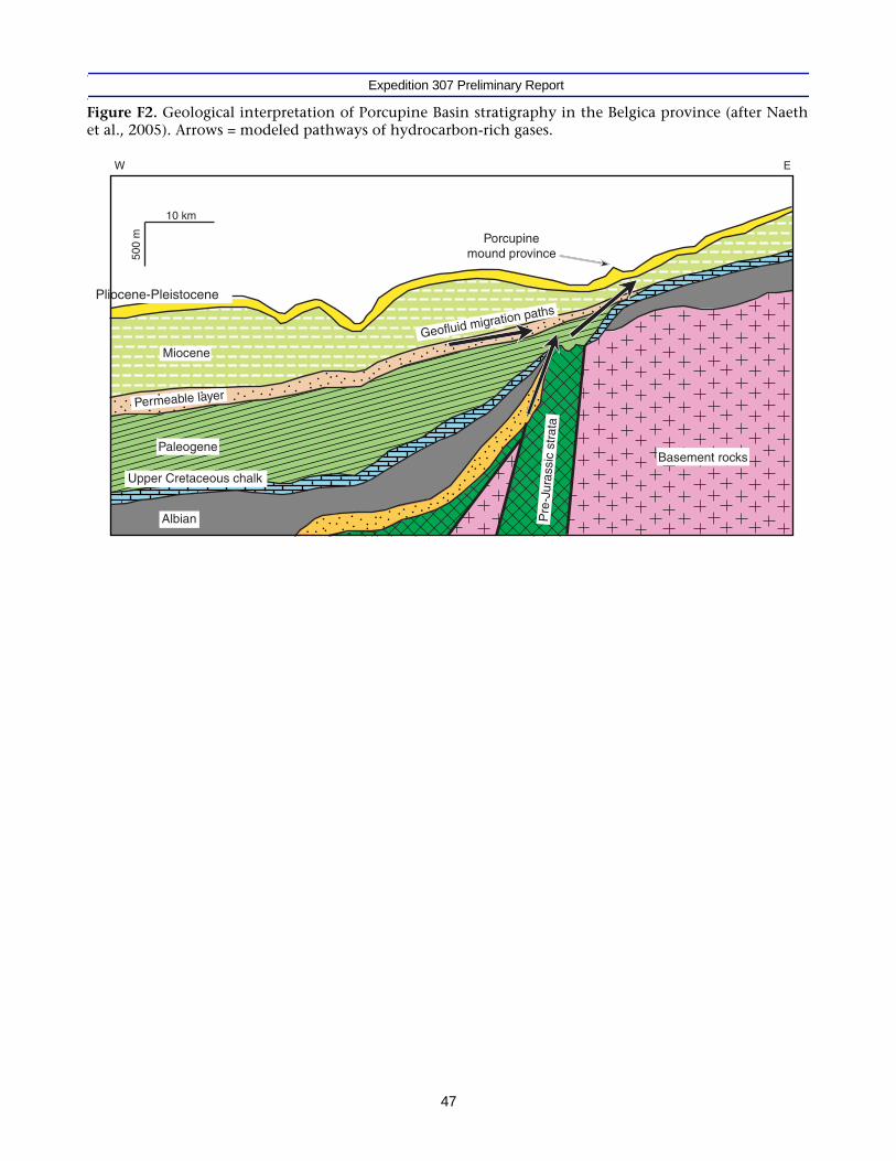
Expedition 307 Preliminary Report
Figure F2. Geological interpretation of Porcupine Basin stratigraphy in the Belgica province (after Naethet al., 2005). Arrows = modeled pathways of hydrocarbon-rich gases.
Permeable layer
Pliocene-Pleistocene
500
m
10 km
W E
Albian Pre
-Jur
assi
c st
rata
Basement rocks
Miocene
Upper Cretaceous chalk
Paleogene
Porcupinemound province
Geofluid migration paths
47

Expedition 307 Preliminary Report
Figure F3. Interpretation of high-resolution seismic profiles underlying Challenger Mound and slope (af-ter De Mol et al., 2002).
Two-
way
trav
elim
e (s
)
BEL28
R2
R3
R4
P1
P2
P1
P3
P3
ChallengerMound
0 5 10
km
P980521 P980525 P000658 P010517
0.6
0.8
1.0
1.2
1.4
1.6
48

Expedition 307 Preliminary Report
Figure F4. High-resolution seismic profile of Challenger Mound along a north-northwest to south-south-east transect. Note the sigmoid shapes to both sides of the mound (from De Mol et al., 2002).
1 km
NNW SSE
P000658
1.1
1.3
1.2
Two-
way
trav
eltim
e (s
)
49

Expedition 307 Preliminary Report
Figure F5. Location of sites in Porcupine Seabight.
Site U1318
Site U1317
Site U1316
010 10
km
11°56'W 11°52' 11°48' 11°54' 11°40' 11°36' 11°32' 11°28' 11°24'
51°32'N
51°28'
51°24'
51°20'
N
S
EW
1000
800
600
400
50

Expedition 307 Preliminary Report
Figure F6. Correlation and interpretation of paleomagnetic inclination results.
Bru
hn
es
Old
uva
i
?
?
?
Bru
hn
es
Bru
hn
es
Hole U1316AInclination (°)
Hole U1317BInclination (°)
Hole U1318BInclination (°)
-90 -60 -30 0 30 60 90 -90 -60 -30 0 30 60 90 -90 -60 -30 0 30 60 90
170
180
190
200
210
220
230
240
Dep
th (
mbs
f)
0
10
20
30
40
50
60
70
80
90
100
110
120
130
140
0
10
20
30
40
50
60
70
80
90
100
110
120
130
140
150
160
0
10
20
30
40
50
60
70
80
90
100
110
120
130
140
150
160
0.78 Ma
0.78 Ma
0.78 Ma0.990 Ma
1.070 Ma
1.770 Ma
1.950 Ma
51

Expedition 307 Preliminary Report
Figure F7. Depth profiles of prokaryote cell counts.
5
Increasein
methane
Dep
th (
mbs
f)
Corals
5 5.5 6 6.5 7 7.5 8 8.5 5 5.5 6 6.5 7 7.5 8 8.55 5.5 6 6.5 7 7.5 8 8.5
Increasein
methane
1A
1B
1C
3A
3B
2
Site U1317Site U1316 Site U1318
Lith.unit
Procaryote cells(Log10numbers/cm3)
Procaryote cells(Log10numbers/cm3)
Procaryote cells(Log10numbers/cm3) Lith.
unitLith.unit
3
2si
lty c
lay
1B
1A
MB
2
1
Cor
al m
ound
seq
uenc
e
0
20
40
60
80
100
120
140
52

Expedition 307 Preliminary R
eport
53
Figure F8. Lithostratigraphic correlation. Geologic ages were estimated from biostratigraphic data.
8
2
3
4
5
6
7
8
9
10
Cor
eR
ecov
ery
Hole C
Site U1316
Dep
th (
mbs
f)
Site U1317 Site U131
9
?
?
? ? <3.6 M
a<3.6 Ma?
Plio
cene
-Ple
isto
cene
Mio
cene
Mio
cene
Mio
cene
Ple
isto
cene
Plio
cene
Coral float- and rudstone
Wackestone
Mudstone
Sand
Silt
Clay
Lamination
No recovery
MBIO samples
0
10
20
30
40
50
60
70
80
90
100
110
120
130
140
150
160
170
180
190
200
210
220
230
240
250
260
270
Ple
isto
cene
Mio
cene
?
Cor
es w
ill b
e op
ened
froz
en
Cor
es w
ill b
e op
ened
froz
en
Cor
es w
ill b
e op
ened
froz
en
1
2
3
4
5
6
7
8
9
10
11
12
13
14
15
1617
2
3
4
5
6
7
8
10
11
12
13
14
15
16
17
1
2
3
4
5
6
7
8
9
10
11
12
13
14
17
1
2
3
4
5
6
7
8
9
10
11
1
2
3
4
5
6
7
1
2
3
4
5
6
7
9
11121315
16
1718
20
21
2
3
4
56
7
8
9
10
11
12
13
14
15
16
17
18
1
2
3
4
5
6
7
8
9
11
12
13
14
15
16
17
10
1
2
3
4
5
6
7
8
9
10
11
12
13
14
15
1
2
3
4
5
6
7
8
9
10
11
12
13
14
15
16
17
19
20
21
22
23
24
25
27
26
18
Cor
eR
ecov
ery
Cor
eR
ecov
ery
Cor
eR
ecov
ery
Cor
eR
ecov
ery
Cor
eR
ecov
ery
Cor
e
Rec
over
y
Cor
eR
ecov
ery
Rec
over
yC
ore
Cor
eR
ecov
ery
Cor
eR
ecov
ery
Hole A Hole B Hole C Hole A Hole B Hole C Hole D Hole E Hole A Hole B

Expedition 307 Preliminary Report
Figure F9. Lithostratigraphy of the three sites projected on the seismic profile of Challenger Mound alonga north-northwest to south-southeast transect.
Two-
way
trav
eltim
e (s
)
0 5 10
km
0.6
0.8
1.0
1.2
1.4
SiteU1316
SiteU1317
SiteU1318
Coral float- and rudstone
Wackestone
Mudstone
Sand
Silt
Clay
Lamination
No recovery
54

Expedition 307 Preliminary Report
Figure F10. Spatial correlation of multisensor track data of lithostratigraphic Unit 1 from Site U1317.
HoleU317A
HoleU1317B
HoleU1317C
HoleU1317D
HoleU1317E
Dep
th (
mbs
f)
0
20
40
60
80
100
120
140
160
180
200
220
240
260
0
20
40
60
80
100
120
140
160
180
200
220
240
260
0
20
40
60
80
100
120
140
160
180
200
220
240
260
0
20
40
60
80
100
120
140
160
180
200
220
240
260
0
20
40
60
80
100
120
140
160
180
200
220
240
260
0 2040
0 2040
0 2040
0 2040
0 2040
MST
MST
MST
MST
MST
1.1
1.2
1.3
1.4
1.5
Two-
way
trav
eltim
e (s
)
A B CD
E0 200 400m
55
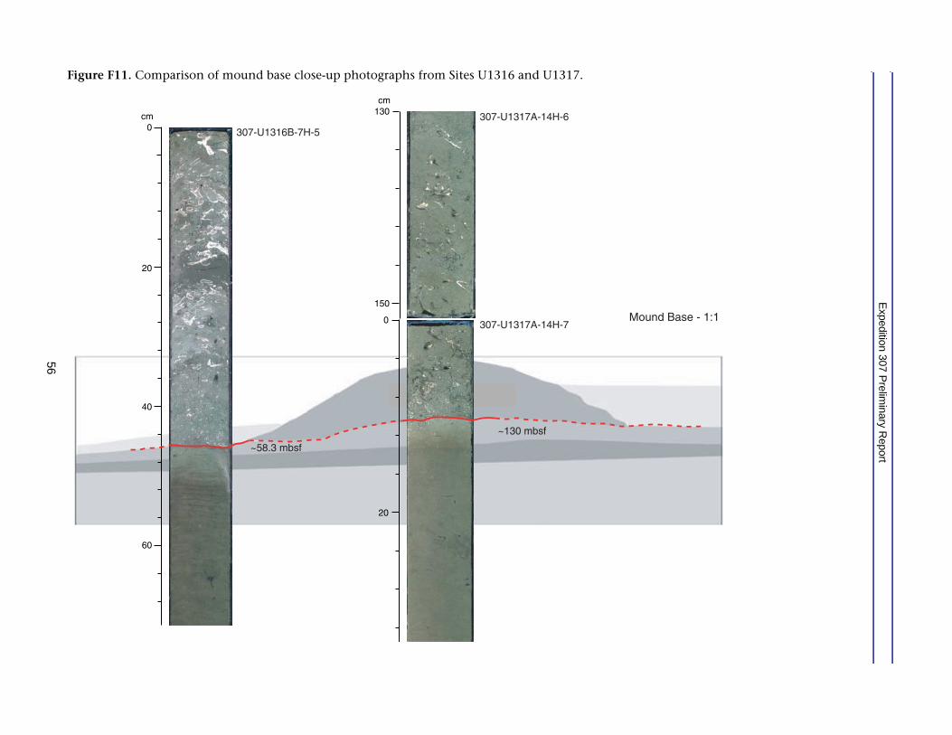
Expedition 307 Preliminary R
eport
56
Figure F11. Comparison of mound base close-up photographs from Sites U1316 and U1317.
ase - 1:1
307-U1316B-7H-5
Mound B
~58.3 mbsf
~130 mbsf
307-U1317A-14H-6
307-U1317A-14H-7
cm
40
60
20
0
20
0
cm
150
130

Expedition 307 Preliminary Report
Figure F12. Results of wireline logging performed in Hole U1317D.
Lith.unit
Dep
th (
mbs
f)
Site U1317ASite U1317BSite U1317CSite U1317DPWSPWL
0
10
20
30
40
50
60
70
80
90
100
110
120
130
140
150
160
170
180
190
200
210
220
230
240
250
(m/s)
VP
(m/s)
Interval velocity
2500
2500
1500
1500
1
2
57

Expedition 307 Preliminary R
eport
58
Figure F13. Geochemical profiles of interstitial water collected in Holes U1317A and U1317D.
Mg Hole U1317AMg Hole U1317DCa Hole U1317ACa Hole U1317D
30 40 50
Mg (mM)
16 20
Ca (mM)
Dep
th (
mbs
f)
SO4 Hole U1317ASO4 Hole U1317DCH4 Hole U1317ACH4 Hole U1317D
0
50
100
150
200
250
3005 10 15 20 25 500 1000 1500 20005 10 15 10 20
Sulfate (mM) Sr (µM)Alkalinity (mM)
8
Methane (ppm)
5000 1x10⁴ 1.5x10⁴ 12