integrated power and...
TRANSCRIPT

Integrated Power and AutomationCatalog Numbers 3300A-IU10J-A1-1, 3300A-IU10J-A1-1-PVP, 3300A-IU10J-A1-1-SSA, 3300A-IU10J-A1-1-PVP-SSA, 3300A-IU10J-A1-2, 3300A-IU10J-A1-2-PVP, 3300A-IU10J-A1-2-SSA, 3300A-IU10J-A1-2-PVP-SSA, 3300A-IU10J-A1-3, 3300A-IU10J-A1-3-PVP, 3300A-IU10J-A1-3-SSA, 3300A-IU10J-A1-3-PVP-SSA, 3300A-IU10J-A1-4, 3300A-IU10J-A1-4-PVP, 3300A-IU10J-A1-4-SSA, 3300A-IU10J-A1-4-PVP-SSA, 3300A-IU10J-B1-1, 3300A-IU10J-B1-1-PVP, 3300A-IU10J-B1-1-SSA, 3300A-IU10J-B1-1-PVP-SSA, 3300A-IU10J-B1-2, 3300A-IU10J-B1-2-PVP, 3300A-IU10J-B1-2-SSA, 3300A-IU10J-B1-2-PVP-SSA, 3300A-IU10J-B1-3, 3300A-IU10J-B1-3-PVP, 3300A-IU10J-B1-3-SSA, 3300A-IU10J-B1-3-PVP-SSA, 3300A-IU10J-B1-4, 3300A-IU10J-B1-4-PVP, 3300A-IU10J-B1-4-SSA, 3300A-IU10J-B1-4-PVP-SSA
Reference ManualOriginal Instructions

Important User Information
Read this document and the documents listed in the additional resources section about installation, configuration, and operation of this equipment before you install, configure, operate, or maintain this product. Users are required to familiarize themselves with installation and wiring instructions in addition to requirements of all applicable codes, laws, and standards.
Activities including installation, adjustments, putting into service, use, assembly, disassembly, and maintenance are required to be carried out by suitably trained personnel in accordance with applicable code of practice.
If this equipment is used in a manner not specified by the manufacturer, the protection provided by the equipment may be impaired.
In no event will Rockwell Automation, Inc. be responsible or liable for indirect or consequential damages resulting from the use or application of this equipment.
The examples and diagrams in this manual are included solely for illustrative purposes. Because of the many variables and requirements associated with any particular installation, Rockwell Automation, Inc. cannot assume responsibility or liability for actual use based on the examples and diagrams.
No patent liability is assumed by Rockwell Automation, Inc. with respect to use of information, circuits, equipment, or software described in this manual.
Reproduction of the contents of this manual, in whole or in part, without written permission of Rockwell Automation, Inc., is prohibited
Throughout this manual, when necessary, we use notes to make you aware of safety considerations.
Labels may also be on or inside the equipment to provide specific precautions.
WARNING: Identifies information about practices or circumstances that can cause an explosion in a hazardous environment, which may lead to personal injury or death, property damage, or economic loss.
ATTENTION: Identifies information about practices or circumstances that can lead to personal injury or death, property damage, or economic loss. Attentions help you identify a hazard, avoid a hazard, and recognize the consequence.
IMPORTANT Identifies information that is critical for successful application and understanding of the product.
SHOCK HAZARD: Labels may be on or inside the equipment, for example, a drive or motor, to alert people that dangerous voltage may be present.
BURN HAZARD: Labels may be on or inside the equipment, for example, a drive or motor, to alert people that surfaces may reach dangerous temperatures.
ARC FLASH HAZARD: Labels may be on or inside the equipment, for example, a motor control center, to alert people to potential Arc Flash. Arc Flash will cause severe injury or death. Wear proper Personal Protective Equipment (PPE). Follow ALL Regulatory requirements for safe work practices and for Personal Protective Equipment (PPE).

Table of ContentsPreface . . . . . . . . . . . . . . . . . . . . . . . . . . . . . . . . . . . . . . . . . . . . . . . . . . . . . . . .5About This Publication . . . . . . . . . . . . . . . . . . . . . . . . . . . . . . . . . . . . . . . . . 5Terminology . . . . . . . . . . . . . . . . . . . . . . . . . . . . . . . . . . . . . . . . . . . . . . . . . . . 5Additional Resources . . . . . . . . . . . . . . . . . . . . . . . . . . . . . . . . . . . . . . . . . . . 6
Chapter 1Introduction to Integrated Power and Automation
Rockwell Automation Integrated Power and Automation . . . . . . . . . 7A Unified Architecture with the IntelliCENTER IEC 61850 Integration Unit . . . . . . . . . . . . . . . . . . . . . . . . . . . . . . . . . . . . . . . . . . . . . . . 8
Chapter 2Components and Core Elements of IPA
Logix Controller . . . . . . . . . . . . . . . . . . . . . . . . . . . . . . . . . . . . . . . . . . . . . . . 9Stratix 5700 Managed Switch . . . . . . . . . . . . . . . . . . . . . . . . . . . . . . . . . . 10ProSoft Gateway . . . . . . . . . . . . . . . . . . . . . . . . . . . . . . . . . . . . . . . . . . . . . . 10Stratix 5950 Security Appliance . . . . . . . . . . . . . . . . . . . . . . . . . . . . . . . . 10PanelView Plus 7 . . . . . . . . . . . . . . . . . . . . . . . . . . . . . . . . . . . . . . . . . . . . . . 11
Chapter 3Connecting IntelliCENTER IEC 61850 Integration Unit Into the Plant Network
Connecting IntelliCENTER IEC 61850 Integration Unit to Electrical Protection Devices. . . . . . . . . . . . . . . . . . . . . . . . . . . . . . . . . 13
IEC-61850 Specifics . . . . . . . . . . . . . . . . . . . . . . . . . . . . . . . . . . . . . . . 14VLAN Segmentation . . . . . . . . . . . . . . . . . . . . . . . . . . . . . . . . . . . . . . 14
Testing, Sizing, and Characterization Guidelines for the IntelliCENTER IEC 61850 Integration Unit . . . . . . . . . . . . . . . . . . . 15
Sample System . . . . . . . . . . . . . . . . . . . . . . . . . . . . . . . . . . . . . . . . . . . . 15Test Configuration . . . . . . . . . . . . . . . . . . . . . . . . . . . . . . . . . . . . . . . . 16Configuration Overview . . . . . . . . . . . . . . . . . . . . . . . . . . . . . . . . . . . 17Test Requirements . . . . . . . . . . . . . . . . . . . . . . . . . . . . . . . . . . . . . . . . 19Evaluation Criteria . . . . . . . . . . . . . . . . . . . . . . . . . . . . . . . . . . . . . . . . 19Test Results . . . . . . . . . . . . . . . . . . . . . . . . . . . . . . . . . . . . . . . . . . . . . . . 19
Converged Plantwide Ethernet (CPwE) Guidelines For Connecting the IntelliCENTER IEC 61850 Integration Unit to PlantPAx Process Automation System . . . . . . . . . . . . . . . . . . . . . . . . . . 21
Simplex Integration. . . . . . . . . . . . . . . . . . . . . . . . . . . . . . . . . . . . . . . . 22Redundant Integration. . . . . . . . . . . . . . . . . . . . . . . . . . . . . . . . . . . . . 23
Index . . . . . . . . . . . . . . . . . . . . . . . . . . . . . . . . . . . . . . . . . . . . . . . . . . . . . . . .25
Rockwell Automation Publication 3300A-RM001A-EN-P - October 2017 3

Table of Contents
Notes:
4 Rockwell Automation Publication 3300A-RM001A-EN-P - October 2017
Preface
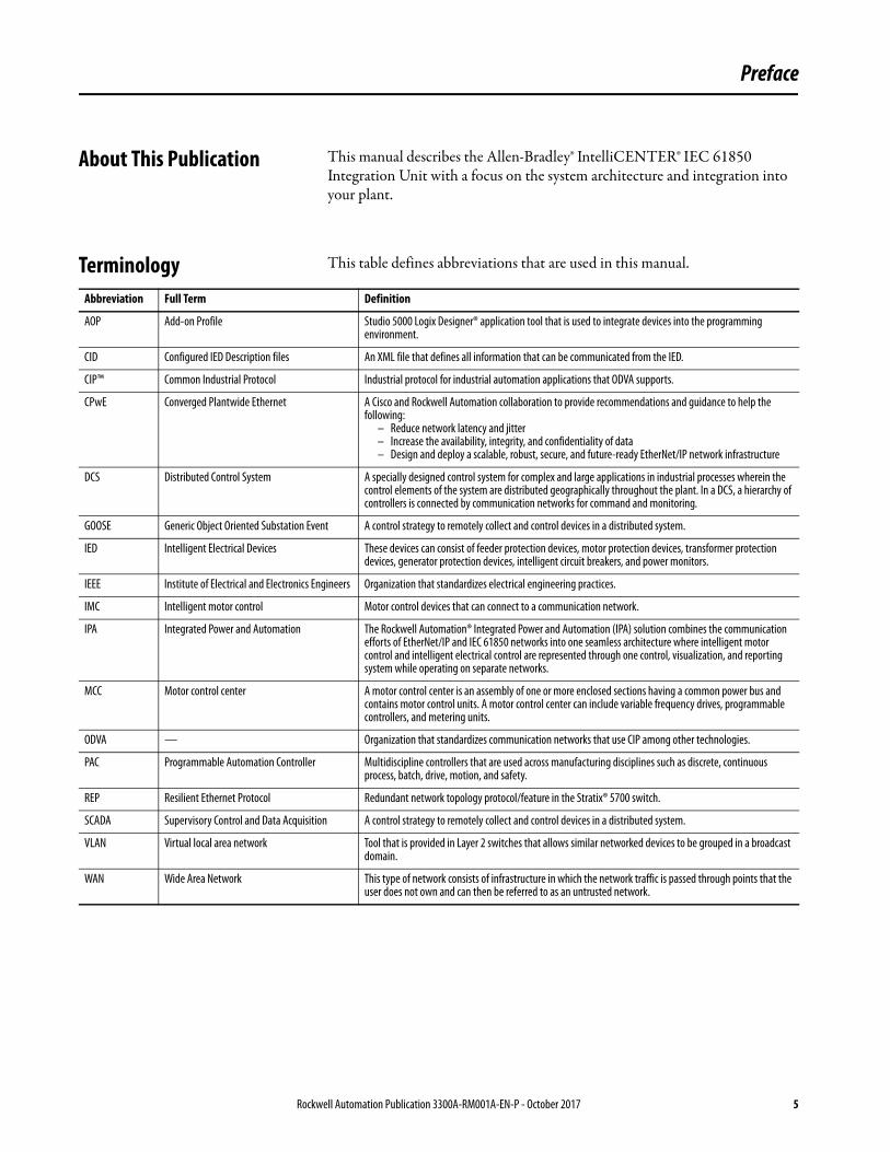
About This Publication This manual describes the Allen-Bradley® IntelliCENTER® IEC 61850 Integration Unit with a focus on the system architecture and integration into your plant.
Terminology This table defines abbreviations that are used in this manual.
Abbreviation Full Term Definition
AOP Add-on Profile Studio 5000 Logix Designer® application tool that is used to integrate devices into the programming environment.
CID Configured IED Description files An XML file that defines all information that can be communicated from the IED.
CIP™ Common Industrial Protocol Industrial protocol for industrial automation applications that ODVA supports.
CPwE Converged Plantwide Ethernet A Cisco and Rockwell Automation collaboration to provide recommendations and guidance to help the following:
– Reduce network latency and jitter– Increase the availability, integrity, and confidentiality of data– Design and deploy a scalable, robust, secure, and future-ready EtherNet/IP network infrastructure
DCS Distributed Control System A specially designed control system for complex and large applications in industrial processes wherein the control elements of the system are distributed geographically throughout the plant. In a DCS, a hierarchy of controllers is connected by communication networks for command and monitoring.
GOOSE Generic Object Oriented Substation Event A control strategy to remotely collect and control devices in a distributed system.
IED Intelligent Electrical Devices These devices can consist of feeder protection devices, motor protection devices, transformer protection devices, generator protection devices, intelligent circuit breakers, and power monitors.
IEEE Institute of Electrical and Electronics Engineers Organization that standardizes electrical engineering practices.
IMC Intelligent motor control Motor control devices that can connect to a communication network.
IPA Integrated Power and Automation The Rockwell Automation® Integrated Power and Automation (IPA) solution combines the communication efforts of EtherNet/IP and IEC 61850 networks into one seamless architecture where intelligent motor control and intelligent electrical control are represented through one control, visualization, and reporting system while operating on separate networks.
MCC Motor control center A motor control center is an assembly of one or more enclosed sections having a common power bus and contains motor control units. A motor control center can include variable frequency drives, programmable controllers, and metering units.
ODVA — Organization that standardizes communication networks that use CIP among other technologies.
PAC Programmable Automation Controller Multidiscipline controllers that are used across manufacturing disciplines such as discrete, continuous process, batch, drive, motion, and safety.
REP Resilient Ethernet Protocol Redundant network topology protocol/feature in the Stratix® 5700 switch.
SCADA Supervisory Control and Data Acquisition A control strategy to remotely collect and control devices in a distributed system.
VLAN Virtual local area network Tool that is provided in Layer 2 switches that allows similar networked devices to be grouped in a broadcast domain.
WAN Wide Area Network This type of network consists of infrastructure in which the network traffic is passed through points that the user does not own and can then be referred to as an untrusted network.
Rockwell Automation Publication 3300A-RM001A-EN-P - October 2017 5

Preface
Additional Resources These documents contain more information about related products from Rockwell Automation.
You can view or download publications athttp://www.rockwellautomation.com/global/literature-library/overview.page. To order paper copies of technical documentation, contact your local Allen-Bradley distributor or Rockwell Automation sales representative.
Resource Description
IntelliCENTER IEC 61850 Integration Unit Installation Instructions, publication 3300A-IN001
Provides installation instructions for the IntelliCENTER IEC 61850 Integration Unit.
IntelliCENTER IEC 61850 Integration Unit Technical Data, publication 3300A-TD001
Provides specifications and unit selection information for the IntelliCENTER IEC 61850 Integration Unit.
CompactLogix™ 5380 Controllers Specifications Technical Data, publication 5069-TD002
Provides specifications, wiring diagrams, and functional block diagrams for CompactLogix 5380 controllers.
1756 ControlLogix® and GuardLogix® Controllers Technical Data, publication 1756-TD001
Provides specifications ControlLogix 5580 controllers.
Stratix Ethernet Device Specifications Technical Data, publication 1783-TD001
Provides specifications for the Stratix switches.
PlantPAx® Rockwell Automation Library for Electrical Protection Devices Reference Manual, publication PROCESS-RM011
Provides information on how to configure the Add-On Instructions that control and monitor intelligent power devices that use the IEC 61850 standard in the PlantPAx system.
ProSoft Communication Gateway User Manual Provides information and specifications for the IEC 61850 to Ethernet network gateway.
CompactLogix 5380 Controllers User Manual, publication 5069-UM001
Provides information on how to use CompactLogix 5380 controllers.
ControlLogix System User Manual, publication 1756-UM001
Provides information on how to use ControlLogix 5580 controllers.
Stratix 5700 Industrial Ethernet Switch Product Profile, publication ENET-PP005
Provides Stratix 5700 switch information.
Stratix 5700 Ethernet Managed Switches User Manual, publication 1783-UM007
Provides Stratix 5700 switch information.
Stratix 5950 Security Appliance User Manual, publication 1783-IN010
Provides a product overview, explains how to connect and configure the security appliance.
PanelView™ Plus 7 Standard Terminals, publication 2711P-UM007
Provides information to install, configure, operate, and troubleshoot the PanelView Plus 7 Standard terminals.
Converged Plant-wide Ethernet (CPwE) Design and Implementation Guide, publication ENET-TD001
Describes how to design a Converged Plantwide Ethernet network.
Industrial Automation Wiring and Grounding Guidelines, publication 1770-4.1
Provides general guidelines for installing a Rockwell Automation industrial system.
Product Certifications website, http://www.rockwellautomation.com/global/certification/overview.page
Provides declarations of conformity, certificates, and other certification details.
6 Rockwell Automation Publication 3300A-RM001A-EN-P - October 2017
Chapter 1
Introduction to Integrated Power and Automation
Rockwell Automation Integrated Power and Automation
Coordination of large distributed measurement and control systems, like SCADA and other process control implementations, requires robust networks that connect thousands of remote devices. Whether it's a new plant or an upgrade, miscommunication between technology vendors and system engineers during design phases can cause future unforeseen integration challenges. With electrical power distribution and automation control systems being traditionally supplied independently, unnecessary complexity and cost throughout the life of the solution can arise.
By using the EtherNet/IP protocol, intelligent motor control devices communicate and work as a part of the process control system. Simultaneously, critical substation equipment communicates with intelligent electrical devices (IED) over an unmodified Ethernet network that is based on the IEC 61850 standard. Both of these communication standards are typically kept independent with separate control, visualization, and reporting environments, which duplicates the effort to monitor devices and keep systems operational.
The Rockwell Automation® Integrated Power and Automation (IPA) solution combines these efforts into one seamless architecture where intelligent motor control and intelligent electrical control are represented through one control, visualization, and reporting system while operating on separate networks. This control is accomplished by bridging a portion of the IEC 61850 traffic into the Studio 5000 Logix Designer® environment and representing important data within FactoryTalk® software for user consumption. Once established, customers can use the Logix Designer application and FactoryTalk software as their single environment for their system architecture.
Some electrical control processes require equipment to be supplied from multiple vendors. Rockwell Automation has partnered with multiple vendors to give customers flexibility and choose the best products to suit their electrical control application needs. Once chosen, Rockwell Automation coordinates the delivery of this equipment in a cost-effective manner, and verifies that the integration of the equipment is seamless on the back end.
Rockwell Automation Publication 3300A-RM001A-EN-P - October 2017 7
Chapter 1 Introduction to Integrated Power and Automation
A Unified Architecture with the IntelliCENTER IEC 61850 Integration Unit
Rockwell Automation has a long history of device connectivity with the Logix Designer application. To deliver a common experience when communicating with devices over the IEC 61850 standard, the IntelliCENTER® IEC 61850 Integration Unit was developed. The integration unit contains standard hardware and standard software to bring a portion of the IEC 61850 traffic into the Logix architecture, delivering ease-of-use and seamless integration.
Inside the integration unit is all equipment necessary to bridge the IEC 61850 traffic into Logix Designer. This equipment includes a gateway for communication bridging, a Stratix® 5700 switch for aggregation of device connections and segmentation, and a ControlLogix® or CompactLogix™ rack. Also, there are options for a PanelView™ terminal for data representation and a Stratix Security Appliance if unsecured upstream connections are required.
Once inside the Logix architecture, the IEDs are monitored within FactoryTalk software with Process Object Library faceplates. By using the integration unit, you can unify power and process systems within the Logix and FactoryTalk environments to create one operating environment.
Faceplates for the Allen-Bradley® 857 Motor Protection Relay, ABB circuit breakers, and Schweitzer protection relays verify that you can choose the appropriate device that meets the needs of your application. These faceplates look and operate like all other Allen-Bradley intelligent devices, delivering a common user interface for the single monitoring and reporting environment.
8 Rockwell Automation Publication 3300A-RM001A-EN-P - October 2017

Chapter 2
Components and Core Elements of IPA
The IntelliCENTER® IEC 61850 Integration Unit contains core components that are part of the configured to order product. By leveraging the control capabilities of a Rockwell Automation® Logix processor, network management from Stratix® managed switches, optional visualization with PanelView™ Plus 7 terminals, and enhanced security functions with the Stratix 5950 Security Appliance, the integration unit enables the intelligent switchgear and intelligent E-house to become part of the Integrated Architecture® system. This system provides ease of integration into the existing network of intelligent motor control devices and lets you take advantage of a unified architecture throughout the facility.
The PlantPAx® distributed control system is a modern DCS that is not only scalable and flexible, but provides functionality, reliability, and performance consistence with expectations from a traditional DCS. The PlantPAx system is able to integrate control systems that use intelligent motor control and intelligent electrical protection devices. The components within the integration unit are essential to make integration possible into a Logix processor and leverage the benefits of the Integrated Architecture system.
Logix Controller When specifying the components inside of the integration unit, there are two options when selecting the programmable controller:
• CompactLogix™ 5380 controller - can be used for mid-range applications such as batch processing or machine control when you need a chassis-based, modular design.
• ControlLogix® 5580 controller - offers increased I/O and network options and is designed to work in distributed or supervisory control applications.
Both the CompactLogix and ControlLogix programmable controllers can be accessed and programmed by using the Logix Designer application.
Rockwell Automation Publication 3300A-RM001A-EN-P - October 2017 9

Chapter 2 Components and Core Elements of IPA
Stratix 5700 Managed Switch The Stratix 5700 managed switches are compact and scalable Layer 2 switches with embedded Cisco technology for use in a wide range of applications from small and isolated to large complex networks. The Stratix 5700 managed switch integrates into Studio 5000® applications.
Industrial-managed Ethernet switches are designed to give you the flexibility and features that helps prevent lost data due to Layer 2 faults and broadcast traffic, which is critical to network performance. With an industrial managed Ethernet switch, network segmentation, such as Virtual LANs (VLANs), and network resiliency, such as Resilient Ethernet Protocol (REP), can be implemented to make sure that network performance is maintained across a complex industrial Ethernet network.
Advanced security, network management, and diagnostics are other critical features that are provided in an industrial managed Ethernet switch. These features make sure that the expected recipient receives the information being sent over the network at the expected time while network issues are allowed to be easily resolved.
For more information on the Stratix 5700 switch, see publication 1783-UM007.
ProSoft Gateway The ProSoft PLX82-EIP61850 gateway module is used to convert the IEC 61850 traffic to EtherNet/IP traffic, which the Logix controller consumes. This conversion makes it possible for the Logix controller to interface with IEC 61850 intelligent electronic devices such as substation protective relays and power monitoring equipment.
Stratix 5950 Security Appliance
The Stratix 5950 Security Appliance incorporates several key security functions into one appliance to help protect your industrial automation infrastructure. The Stratix 5950 Security Appliance provides control to network traffic.
The typical Wide Area Network (WAN) consists of infrastructure in which the network traffic is passed through points that the user does not own and can then be referred to as an untrusted network. The integration unit can be configured with a Stratix 5950 Security Appliance to interface with the untrusted network.
For more information on the Stratix 5950 Security Appliance, see publication 1783-UM010.
10 Rockwell Automation Publication 3300A-RM001A-EN-P - October 2017

Components and Core Elements of IPA Chapter 2
PanelView Plus 7 The optional PanelView Plus 7 terminal is an operator interface device that is used to monitor and control devices that are connected to the CompactLogix or ControlLogix controller over an EtherNet/IP network. The terminal can be used to display information critical to the IED or process, and provide quick diagnostics and ability to configure the system.
Rockwell Automation Publication 3300A-RM001A-EN-P - October 2017 11

Chapter 2 Components and Core Elements of IPA
Notes:
12 Rockwell Automation Publication 3300A-RM001A-EN-P - October 2017
Chapter 3
Connecting IntelliCENTER IEC 61850 Integration Unit Into the Plant Network
Within the Unified Architecture, it is important that a developed network is not only robust for the current needs of operations, but allows the system infrastructure to evolve over time without requiring a substantial overhaul. This chapter focuses on the process and recommended practices for connecting the IntelliCENTER® IEC 61850 Integration Unit to the plant-wide network infrastructure.
Connecting IntelliCENTER IEC 61850 Integration Unit to Electrical Protection Devices
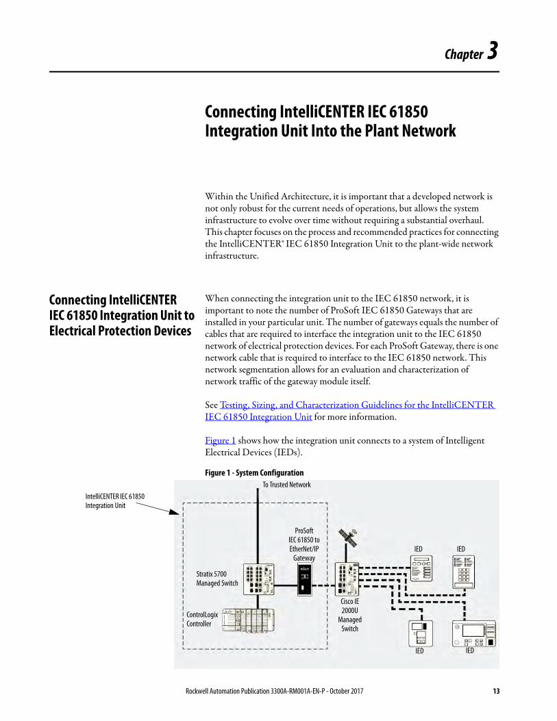
When connecting the integration unit to the IEC 61850 network, it is important to note the number of ProSoft IEC 61850 Gateways that are installed in your particular unit. The number of gateways equals the number of cables that are required to interface the integration unit to the IEC 61850 network of electrical protection devices. For each ProSoft Gateway, there is one network cable that is required to interface to the IEC 61850 network. This network segmentation allows for an evaluation and characterization of network traffic of the gateway module itself.
See Testing, Sizing, and Characterization Guidelines for the IntelliCENTER IEC 61850 Integration Unit for more information.
Figure 1 shows how the integration unit connects to a system of Intelligent Electrical Devices (IEDs).
Figure 1 - System Configuration
IntelliCENTER IEC 61850 Integration Unit
To Trusted Network
Stratix 5700 Managed Switch
ControlLogix Controller
ProSoft IEC 61850 to EtherNet/IP
Gateway
Cisco IE2000U
Managed Switch
IED IED
IEDIED
Rockwell Automation Publication 3300A-RM001A-EN-P - October 2017 13

Chapter 3 Connecting IntelliCENTER IEC 61850 Integration Unit Into the Plant Network
IEC-61850 Specifics
The IntelliCENTER IEC 61850 Integration Unit has been tested and characterized for the performance of a 40 IED system in an MMS client configuration.
When connecting to an IEC 61850 switch, note the following considerations:• The switch supports IEEE C37.238 (Power Profile PTP) if time
synchronization required.• The switch supports a Quality of Service (QoS) specifically for IEDs.
VLAN Segmentation
The best way to segment IEC 61850 traffic is by using virtual local area networks (VLANs). This methodology lets you configure ports on a managed switch in a logical fashion for traffic management. For example, IEC 61850 traffic is subjected to ports where IEDs are connected, while HMI traffic is segmented on another VLAN, thus reducing the amount of traffic on each logical network. Use best practices to separate the ports for which the ProSoft modules are connected to on the IEC 61850 network to minimize the amount of multicast and GOOSE (Generic Object Oriented Substation Event) traffic to those switch ports.
IMPORTANT For each ProSoft module in the integration unit, there is one network connection to the IEC 61850 network.The network infrastructure (provided outside the integration unit) must be selected and sized to handle the IEC 61850 traffic loading.
IMPORTANT All testing and validation that is provided in this document was done based on MMS buffered reports and MMS commands. None of the characterization testing that is provided for this document included GOOSE subscriber functionality.
14 Rockwell Automation Publication 3300A-RM001A-EN-P - October 2017

Connecting IntelliCENTER IEC 61850 Integration Unit Into the Plant Network Chapter 3
Testing, Sizing, and Characterization Guidelines for the IntelliCENTER IEC 61850 Integration Unit
The integration unit is a flexible system that you can scale to fit multiple applications. Application size and system response requirements are the two main drivers that are used for the sizing of the integration unit for an application. This section discusses how the system was tested and suggests recommended settings for operation of the integration unit.
Sample System
It is recognized that most industrial and commercial power systems consist of various IEDs based on function. Systems can consist of feeder protection devices, motor protection devices, transformer protection devices, generator protection devices, intelligent circuit breakers, and power monitors. The testing of the integration unit is based on a 40 IED system that is shown in Figure 2.
Figure 2 - Typical Industrial and Commercial Power System
This representative system consists of three voltage levels and on-site generation that feeds various loads and motors at both medium and low voltage. For this test, we use SEL 700 series IEDs (Schweitzer Engineering Laboratories) to provide traffic loading on the system. Specifically, we used SEL 700G, 787, 751A, and 710 IEDs for testing.
Utility Feed
SEL 787
SEL 787
SEL 787
SEL 751A SEL 751A SEL 751A SEL 751A SEL 751A SEL 751A SEL 751A SEL 751ASEL 751A
SEL 751ASEL 751ASEL 751ASEL 751ASEL 751A
SEL 710 SEL 710
SEL 710SEL 710
SEL 700G SEL 700G
Transformer 1
Transformer 2
Transformer 3
G1 G2
M1 M2
M4M3
Rockwell Automation Publication 3300A-RM001A-EN-P - October 2017 15
Chapter 3 Connecting IntelliCENTER IEC 61850 Integration Unit Into the Plant Network
Test Configuration
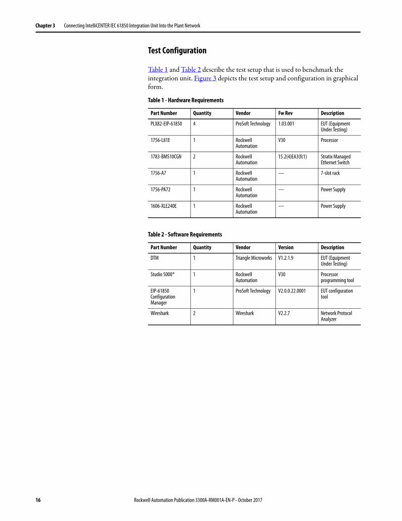
Table 1 and Table 2 describe the test setup that is used to benchmark the integration unit. Figure 3 depicts the test setup and configuration in graphical form.
Table 1 - Hardware Requirements
Part Number Quantity Vendor Fw Rev Description
PLX82-EIP-61850 4 ProSoft Technology 1.03.001 EUT (Equipment Under Testing)
1756-L81E 1 Rockwell Automation
V30 Processor
1783-BMS10CGN 2 Rockwell Automation
15.2(4)EA3(fc1) Stratix Managed Ethernet Switch
1756-A7 1 Rockwell Automation
— 7-slot rack
1756-PA72 1 Rockwell Automation
— Power Supply
1606-XLE240E 1 Rockwell Automation
— Power Supply
Table 2 - Software Requirements
Part Number Quantity Vendor Version Description
DTM 1 Triangle Microworks V1.2.1.9 EUT (Equipment Under Testing)
Studio 5000® 1 Rockwell Automation
V30 Processor programming tool
EIP-61850 Configuration Manager
1 ProSoft Technology V2.0.0.22.0001 EUT configuration tool
Wireshark 2 Wireshark V2.2.7 Network Protocol Analyzer
16 Rockwell Automation Publication 3300A-RM001A-EN-P - October 2017
Connecting IntelliCENTER IEC 61850 Integration Unit Into the Plant Network Chapter 3
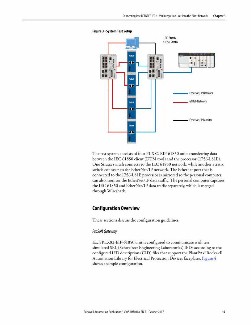
Figure 3 - System Test Setup
The test system consists of four PLX82-EIP-61850 units transferring data between the IEC 61850 client (DTM tool) and the processor (1756-L81E). One Stratix switch connects to the IEC 61850 network, while another Stratix switch connects to the EtherNet/IP network. The Ethernet port that is connected to the 1756-L81E processor is mirrored so the personal computer can also monitor the EtherNet/IP data traffic. The personal computer captures the IEC 61850 and EtherNet/IP data traffic separately, which is merged through Wireshark.
Configuration Overview
These sections discuss the configuration guidelines.
ProSoft Gateway
Each PLX82-EIP-61850 unit is configured to communicate with ten simulated SEL (Schweitzer Engineering Laboratories) IEDs according to the configured IED description (CID) files that support the PlantPAx® Rockwell Automation Library for Electrical Protection Devices faceplates. Figure 4 shows a sample configuration.
EIP Stratix61850 Stratix
EtherNet/IP Network
61850 Network
EtherNet/IP Monitor
Rockwell Automation Publication 3300A-RM001A-EN-P - October 2017 17

Chapter 3 Connecting IntelliCENTER IEC 61850 Integration Unit Into the Plant Network
Figure 4 - Sample Configuration
Each PLX82-EIP-61850 module is configured to read three reports and write eight controllable points from/to each IED. Table 3 shows the breakdown of attributes from each device and their assignment to each report.
IEC 61850 Communication Overview
The DTM software simulates 40 IEDs based on the CID files from the Rockwell Automation Library for Electrical Protection Devices, publication PROCES-RM011. Table 4 provides a configuration overview of the relevant CID settings and IEC 61850 data traffic that the DTM tool generates.
Table 3 - Device Attributes
IEC 61850 Communication Method
Mode Dataset Data Count
Report Buffered DSet01 41 data attributes
Report Buffered DSet02 134 data attributes
Report Buffered DSet03 32 data attributes
Control Direct/Normal Security - 8 controllable points
Table 4 - Configuration Overview
Communication Method Attribute Description
Buffered Report Count per IED 3
Buffered Report Trigger Options Data change (dchng) and Integrity Period (IntPd) (all reports)
Buffered Report Integrity Period DSet01: 1000 ms, DSet02: 5000 ms, DSet03: 1000 ms
Buffered Report Data change frequency 25% of the data attributes change data every 30 seconds
Buffered Report Buffer Time 500 ms (all reports)
Unbuffered Report Count per IED 0
GOOSE control block Count per IED 0
MMS read operation Count per IED 0
Control Count per IED 8 controllable points
Control Operate frequency Each control operation is issued every 1000 ms
18 Rockwell Automation Publication 3300A-RM001A-EN-P - October 2017

Connecting IntelliCENTER IEC 61850 Integration Unit Into the Plant Network Chapter 3
EtherNet/IP Configuration
Table 5 provides the information for the configuration of the EtherNet/IP network configuration for the ProSoft Gateway module within the integration unit.\
Test Requirements
The following logic is written in the ControlLogix® controller:• Class 1 connection timeout - Monitor the number of timeouts for each
connection during the testing period.• Report data update timing - Measure the maximum time interval
without data change.• Control operation - Trigger eight control operations for each IED every
1000 ms.
Evaluation Criteria
Table 6 shows the criteria that are used to evaluate a valid test of the system.
Test Results
The following sections show the results for multi-module system and single module system testing.
Table 5 - ProSoft Gateway Module EtherNet/IP Network Configuration
Attribute Value
Number of Connections (per EUT) 20
RPI 100 ms
Connection size 500 bytes input / 496 bytes output
Connection type Unicast
Table 6 - Evaluation Criteria
Test Criteria Pass Criteria
EtherNet/IP timeouts No timeouts observed
EtherNet/IP jitter Within 5% of the requested RPI time
Report timing Change 25% of data every 30 seconds
Control timing Trigger eight commands each device every 1 second
IEC 61850 TCP/IP timeouts No timeouts that the EUT causes
Rockwell Automation Publication 3300A-RM001A-EN-P - October 2017 19

Chapter 3 Connecting IntelliCENTER IEC 61850 Integration Unit Into the Plant Network
Multi-module System
Figure 5 defines the system stability for a system that contains 10…40 IEDs. The points within the chart represent test data that, where the actual measured RPI time, between the ProSoft Gateway module and the ControlLogix controller, is within 5% of the configured RPI time. As multiple, fully loaded modules are added within the system, the system scales linearly.
Figure 5 - System RPI Settings
Linear (RPISetting [ms])
RPI Setting [ms]
y = 0.4x + 55R² = 0.8
Number of IEDs
RPI T
ime [
ms]
00
10 20
20
30 40
40
50
60
80
100
120
20 Rockwell Automation Publication 3300A-RM001A-EN-P - October 2017

Connecting IntelliCENTER IEC 61850 Integration Unit Into the Plant Network Chapter 3
Single Module System
Figure 6 defines the system stability for a system that contains between 1…10 IEDs. The points within the chart represent test data that, where the actual measured RPI time, between the ProSoft Gateway module and the ControlLogix controller, is within 5% of the configured RPI time. As IEDs are added to the module, the RPI response time scales linearly.
Figure 6 - Loading of Single ProSoft PLX 82 Module
See the IntelliCENTER Integration Unit Specifications Technical Data, publication 3300A-TD001 for specifications.
Converged Plantwide Ethernet (CPwE) Guidelines For Connecting the IntelliCENTER IEC 61850 Integration Unit to PlantPAx Process Automation System
The integration unit can be integrated into the PlantPAx distributed control system. The integration unit acts as another process skid or instrument to be connected into the overall PlantPAx architecture. The programmable controller within the integration unit is also considered like a remote terminal unit (RTU) within the process architecture. This information is directly produced to the HMI and the reporting layer while also producing the same data to other controllers for control operations within the system. For more information about the PlantPAx system architecture, consult the PlantPAx Distributed Control System Reference Manual, publication PROCES-RM001.
Rockwell Automation Publication 3300A-RM001A-EN-P - October 2017 21

Chapter 3 Connecting IntelliCENTER IEC 61850 Integration Unit Into the Plant Network
Figure 7 - System Architecture
Simplex Integration
When integrating into a simplex system, connect the uplink on the Stratix 5700 switch that is provided in the integration unit with the process level switch that is provided within the PlantPAx system architecture. Consult the PlantPAx Distributed Control System Reference Manual, publication PROCES-RM001 for further guidance on port configuration. See the Converged Plant-wide Ethernet (CPwE) Design and Implementation Guide, publication ENET-TD001 for network topology guidance.
The PlantPAx Distributed Control System is a modern DCS which is scalable, flexible, and open while providing the reliability, functionality, and performance expected from a DCS. The PlantPAx System is capable of integrating control systems on process skidded equipments, process instrumentation, intelligent motor control and intelligent electrical protection devices. This drawing depicts a typical reference architecture for the PlantPAx System.
Virtual LANs provide the proper automation system segregation,
where the critical communication is in the same subnet.
Process AutomationAnd Application
Servers
OperatorWorkstations
EngineeringWorkstations
The Domain Controller is responsible to propagate the
system time to computers and network infrastructure devices.
Network Time Protocol (NTP) source can be internal or external,
the GPS source (internal) is preferable in system where the time synchronization is critical.
Skids of electrical protection devices can now be easily
integrated into the PlantPAx System providing a holistic view of your plant’s operations from power infrastructure through
process control equipment.
Process Controllers responsible to handle Process I/O and Motor
Control Center.
Routing capabilities such as Hot Standby
Routing Protocol (HSRP) is used in
secondary activities.
Domain Controller
Process Automation And Application Servers
NTP
NTP
Process Control I/O Network Intelligent Electrical Protection Devices
Intelligent Motor Control Devices PTP
VLAN SegmentationManagement (300)Native - Trunk (301)Supervisory Network (501)MCC I/O Network (502)Process I/O Network (503)
IEC 61850 Network (505)RTU I/O Network (504)
PTP
NTP
22 Rockwell Automation Publication 3300A-RM001A-EN-P - October 2017
Connecting IntelliCENTER IEC 61850 Integration Unit Into the Plant Network Chapter 3
Redundant Integration
When integrating into a redundant system, consider items including network architecture, controller size, and device ownership. Connect the uplink on the Stratix 5700 switch that is provided in the integration unit to the process level switch provided within the PlantPAx system architecture. Consult the PlantPAx Distributed Control System Reference Manual, publication PROCES-RM001 for further guidance on port configurations and controller sizing and impact for redundant systems. See the Converged Plant-wide Ethernet (CPwE) Design and Implementation Guide, publication ENET-TD001 for network topology guidance.
Rockwell Automation Publication 3300A-RM001A-EN-P - October 2017 23

Chapter 3 Connecting IntelliCENTER IEC 61850 Integration Unit Into the Plant Network
Notes:
24 Rockwell Automation Publication 3300A-RM001A-EN-P - October 2017

Index
Aabbreviations 5Add-on Profiles 5
Cconfiguration guidelines
ProSoft gateway 17connect integration unit 13controller 21
CompactLogix™ 9ControlLogix® 9
converged plantwide Ethernet system See CPwE
CPwEconnect integration unit 21redundant system 23simplex system 22
DDCS 9
Ffaceplates 8
Ggateway 13, 17GOOSE subscriber functionality 14
IIEC 61850 gateway 10, 13IEC 61850 network 13IED 13, 15IEEE C37.238 14industrial Ethernet switch
managed 10Integrated Architecture® 9integrated power and automation See IPAintegration unit 8, 9, 13intelligent electrical devices See IEDIPA 7
Llayer 2 switch 10
Mmanaged Ethernet switch 10
advanced security 10diagnostics 10network management 10
MMS client configuration 14
Nnetwork segmentation 13
Ooperator interface 11
PPlantPAx® system 9process object library 8programmable controller 9
Qquality of service 14
Rredundant system 23Resilient Ethernet Protocol 10RPI time 20, 21
Ssimplex system 22size guidelines 15
Tterminology 5test guidelines 15
configuration 17EtherNet/IP communication 19IEC 61850 communication 18system setup 15, 16, 17
test resultsRPI time 20, 21
time synchronization 14trusted network 13
Rockwell Automation Publication 3300A-RM001A-EN-P - October 2017 25

Index
Uunified architecture 8, 13untrusted network 10uplink 22
VVirtual LAN 10VLAN 14
WWAN 10
26 Rockwell Automation Publication 3300A-RM001A-EN-P - October 2017


Publication 3300A-RM001A-EN-P - October 2017 PN-PN-123456Supersedes Publication Publication Number - Month Year Copyright © 2017 Rockwell Automation, Inc. All rights reserved. Printed in the U.S.A.
Rockwell Automation SupportUse the following resources to access support information.
Documentation FeedbackYour comments will help us serve your documentation needs better. If you have any suggestions on how to improve this document, complete the How Are We Doing? form at http://literature.rockwellautomation.com/idc/groups/literature/documents/du/ra-du002_-en-e.pdf.
Technical Support Center Knowledgebase Articles, How-to Videos, FAQs, Chat, User Forums, and Product Notification Updates. https://rockwellautomation.custhelp.com/
Local Technical Support Phone Numbers Locate the phone number for your country. http://www.rockwellautomation.com/global/support/get-support-now.page
Direct Dial Codes Find the Direct Dial Code for your product. Use the code to route your call directly to a technical support engineer. http://www.rockwellautomation.com/global/support/direct-dial.page
Literature Library Installation Instructions, Manuals, Brochures, and Technical Data. http://www.rockwellautomation.com/global/literature-library/overview.page
Product Compatibility and Download Center (PCDC)
Get help determining how products interact, check features and capabilities, and find associated firmware. http://www.rockwellautomation.com/global/support/pcdc.page
.
Rockwell Otomasyon Ticaret A.Ş., Kar Plaza İş Merkezi E Blok Kat:6 34752 İçerenköy, İstanbul, Tel: +90 (216) 5698400
Rockwell Automation maintains current product environmental information on its website at http://www.rockwellautomation.com/rockwellautomation/about-us/sustainability-ethics/product-environmental-compliance.page.
Allen-Bradley, CompactLogix, ControlLogix, FactoryTalk,GuardLogix, IntelliCENTER, PanelView, PlantPAx, Rockwell Automation, Rockwell Software, Stratix, Studio 5000, and Studio 5000 Logix Designer are trademarks of Rockwell Automation, Inc.
Trademarks not belonging to Rockwell Automation are property of their respective companies.