integrated tapered slot antenna arrays …€¦ · · 2010-07-16page 176 first international...
TRANSCRIPT
Page 176 First International Symposium on Space Terahertz Technology
INTEGRATED TAPERED SLOT ANTENNA ARRAYSAND DEVICES
K. Sigfrid Mgvesson
Department of Electrical and Computer EngineeringUniversity of Massachusetts
Amherst, MA 01003
ABSTRACT
The potential advantages of integrating antenna elements/arrays with active deviceshas made this into an area which has received increasing emphasis among millimeterwave/submillimeter wave researchers. This paper reviews the status of one type ofantenna element which shows great promise for such applications - the Tapered SlotAntenna (TSA). We will cover some recent advances in this area, with particular emphasison the potential application of TSA arrays in THz Space Technology. Examples are givenof applications with relevance to THz Space Technology in three areas: (1) Focal planearrays for imaging; millimeter wave prototypes at 35 and 94 GHz have demonstratedsystem aperture efficiencies (i.e. total coupling efficiencies) of over 50%, with angularresolution close to the Rayleigh criterion. (2) Quasi-optical power-combining with highradiative efficiency, as demonstrated by a 32 GHz prototype developed together withJPL. (3) Integrated receivers, such as SIS mixers, and a new two-dimensional electron gaselement.

First International Symposium on Space Terahertz Technology Page 177
REVIEW OF TSA ELEMENTS AND ARRAYS
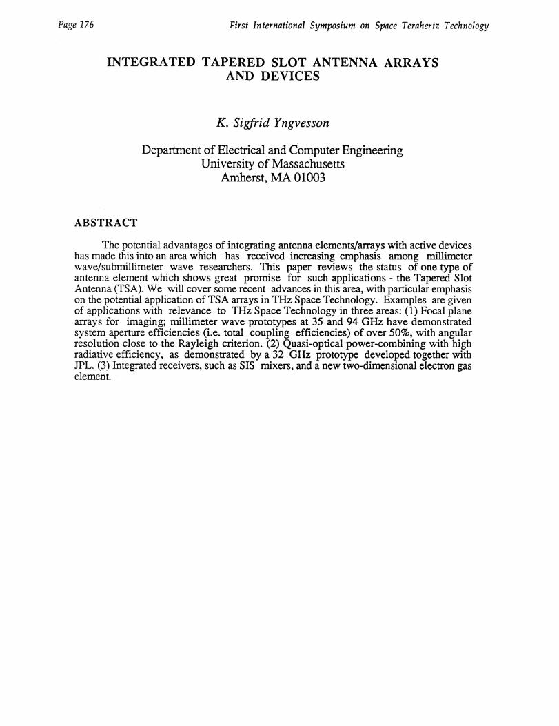
Endfire antenna elements of the tapered slot antenna (TSA) type can be employedboth as single elements and in arrays. TSAs utilize a tapered slot in the metalization on athin dielectric substrate, to radiate in the "end-fire" direction (along the tapered slot, seeFigure 1). The special case of air dielectric also has been investigated. Some distinctiveadvantages of the TSA elements are (1) the 3 dB beamwidth can be varied over a widerange, down to about 15 degrees (2) ease of fabrication by photoetching, and integrationwith active elements (3) high packing density when used in arrays (4) high efficiency inphased arrays even with element spacings greater than 1 X.
Integrated millimeter wave TS A elements were pioneered by Gibson [1] whodemonstrated a bandwidth of 8-40 GHz for an exponentially tapered ("Vivaldi") singleelement, matched to a detector. Since that time, theoretical work by Schaubert and co-workers [2, 3] as well as Johansson [4] has provided a fairly complete picture of theprocess by which single element TSAs radiate. While TSA elements have many features incommon with the general class of traveling-wave antennas, there are some differences: forexample, the H-plane beamwidth often follows the (1/1, 1/2) dependence expected fortraveling-wave antennas (L = antenna length), while the E-plane beamwidth also dependson the aperture size, and varies more slowly with L [2, 3, 5]. A complete moment-methodsolution has been presented for the air-dielectric case, and a simplified linearly taperedgeometry [4]. Radiation patterns (both co-polarized and cross-polarized) are predictedcorrectly. An unsolved case is the single element on a dielectric, with a finite substratewidth.
As indicated by both theoretical and experimental studies, TSA patterns can have highcross-polarization levels in the diagonal (D) plane. The lowest X-pol levels (10-15below the Co-Pol peak) are obtained for exponentially tapered elements, with an optimumdielectric thickness. For these elements, the integrated power lost to X-Pol, is about 10%.Phase centers have also been predicted and measured in recent work — typically, the E-plane phase center is somewhat behind the aperture, while the H-plane one is furthertoward the feed-point. A Vivaldi element has been used in one experiment as the feed foran f/D = 1 paraboloid reflector. The dependence of the gain on the axial displacementindicated that for this element E- and H-plane phase centers were close. The apertureefficiency of this system was estimated to be --55% by direct substitution with a waveguidehorn. TSA elements used as feeds for reflectors or lenses, thus yield comparable systemaperture efficiency to typical waveguide feeds.
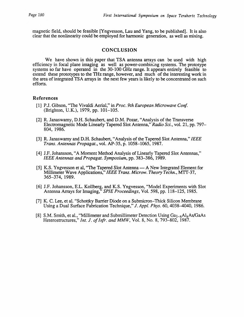
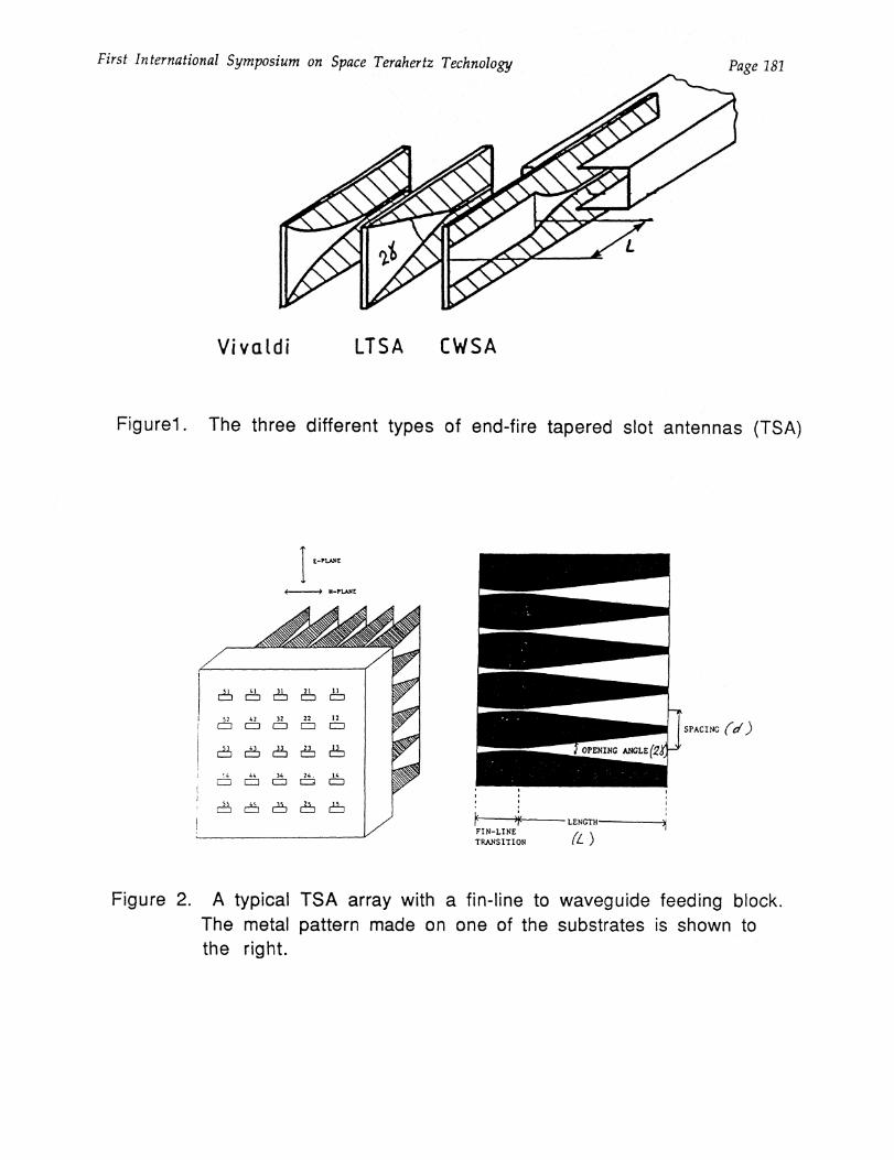
Arrays of TSA elements (Figure 2 shows an example) have a number of usefuladvantages. They have been employed in the focal plane of a reflector, in order to form amulti-beam system for millimeter wave imaging. One such system demonstrated resolutionof two point sources at the Rayleigh distance [6]. When compared at the same beamwidth(to illuminate a specific reflector optimally), elements in a TSA array occupy about 1/4 ofthe area of a typical waveguide feed element. Thus, imaging systems with TSA focal planearrays (Figure 3) can be designed to yield high angular resolution (due to small elementspacing) while retaining high aperture efficiency. In other multi-beam systems, TSA arrayscould be used if a high cross-over level is desired.
Most of the work on TSA elements and arrays thus far has utilized substratessuch as low-4 Duroid, or Kapton (Cr = 3.5), and has been limited to 35 or 94 GHz.Recent work has emphasized techniques for enabling TSA arrays to be used at THzfrequencies. Kollberg et al are developing a 16 element TS A array for 100 GHz, withintegrated SIS mixers, to be used as a focal plane array in a 20 meter diameter radio

Page 178 First International Symposium on Space Terahertz Technology
telescope. The Chalmers University group is also developing TSA elements to beintegrated with SIS mixers at 300 GHz [5]. The substrates used are quartz and silicon.The University of Massachusetts group is developing TSAs on GaAs and silicon, to beintegrated with Two-dimensional electron gas elements to be described below. Themost important constraint is that there is an optimum substrate thickness, which decreasesas the dielectric constant goes up. As a rule of thumb, one can use the followingrelationship:
-e-ff = .03 - .04 (1)
where,
teff = t x (Er - 1) (2)
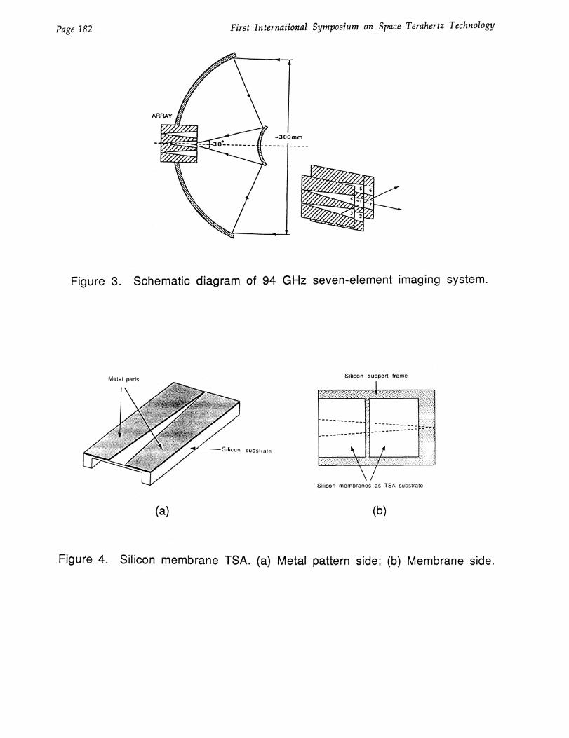
The optimum thickness (t) of a silicon substrate (with er = 11.8) for a 100 GHz TSAis about 5-10 micrometers. One approach for achieving the required thickness of thesubstrate is to etch semiconductor substrates, such as silicon or GaAs. The optimumthickness is considerably greater than the typical membrane thickness in the work of KevinC. Lee, J. Silcox, et al. [7]. A design being tested at the University of Massachusetts isshown in Figure 5. This design includes a cross-bar for added mechanical strength. Modelexperiments showed that the cross-bar has negligible effect on the radiation pattern of theelement.
QUASI-OPTICAL POWER-COMBINING WITH TSA ARRAYS
Power-combining of a number of sources or power amplifiers is a promisingapproach to the problem of obtaining higher power output for a number of millimeter waveapplications. Traditional designs employ microstrip or waveguide combining networks. Ifa fairly large number (10-100) of sources are to be combined, microstrip networks becomevery lossy at millimeter waves. We have demonstrated an active array approach, which ispredicted to have an efficiency which is essentially independent of the number of elements.The combiner is intended to be used with the spacecraft transmitters in the NASA deep-space communication network, which is being extended for operation at 32 GHz. Thetransmitter power will first be split into a number of channels, and amplified by MMICpower amplifiers. The output from the amplifiers will be fed to the elements of a phasedarray, designed with TSA (Tapered Slot Antenna) radiators. The array thus combines thepower of the amplifiers, and feeds it into a near-field Cassegrain reflector system, asillustrated in Figure 5. Circular polarization will be obtained from the linearly polarizedarray via a polarizer, indicated in Figure 5. The array is also designed for scanning (± 10°)by incorporating MMIC phase-shifters in each channel - the corresponding scan for thereflector system is ± 1°.
The optimum element spacing depends in an array of this type on a number offactors, such as the optical system, packing density of the MMIC chips, etc. A spacing ofd = 1.224 has been chosen based on such considerations. Element 3 dB beamwidths of30-40° are being used to effectively cut down the grating lobes which arise at this spacing.We have studied the predicted array directivity which can be achieved when elements withideal (cos0)q active element patterns are used. The array directivity has been calculated fora 21 element two-dimensional array configuration which is presently being developed. The

First International Symposium on Space Terahertz Technology Page 179
predicted directivity (D) should be compared with the maximum directive gain (Gmax)allowed by the total array area for a given element spacing. The area efficiency can bedefined as lA = D/Gmax, and is plotted in Figure 7. It is clear that very high areaefficiencies are feasible.
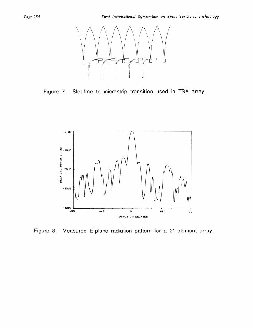
A transition to microstrip has been developed for the TSA elements as shown inFigure 7. One of the several substrates (10 mil Duroid 5880) which are used in the two-dimensional array is shown. Dummy TSA elements are used as edge elements to ensurethat all active elements have similar patterns.
We have tested a two-dimensional array, fed from a microstrip power divider. Themeasured E-plane pattern, as shown in Figure 8, is very close to the predicted pattern.
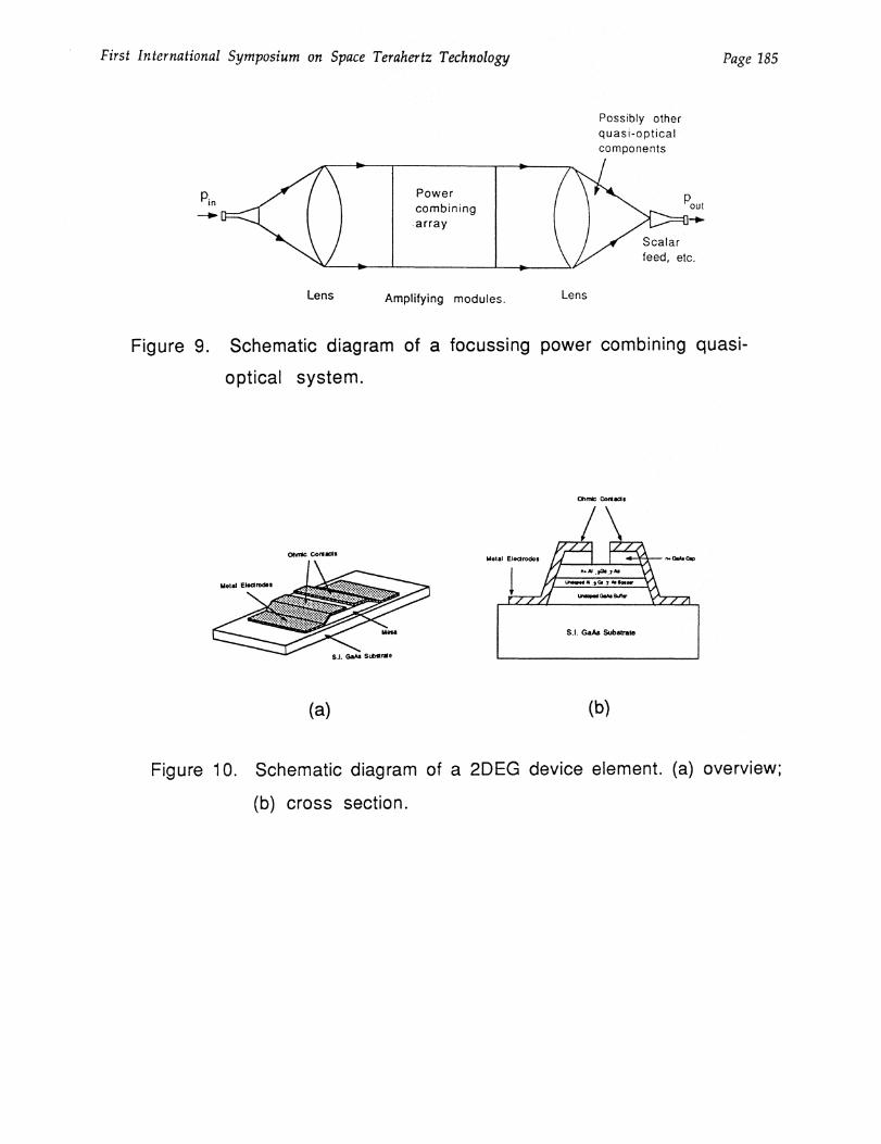
Power-combining arrays of the above type are best used with power amplifier elements,or with injection-locked oscillators. Power-amplifiers and injection-locked oscillators aregenerally found to have higher output power, and have lower noise, than when a deviceof the same family (MESFET, IMPATT, etc.) is used as a free-running oscillator. A TSAarray quasi-optical power-combiner therefore has considerable potential as a high-powermillimeter wave source, which could also have low near-carrier noise. The power-divider would most conveniently be accomplished by using quasi-optical techniques, asshown in Figure 9. Such a power-combiner could be a convenient future source of THzpower, especially if the active devices could be fabricated monolithically.
TWO-DIMENSIONAL ELECTRON GAS ELEMENTS FOR MIXING ANDHARMONIC GENERATION
While both SIS and Schottky-barrier ixer diodes have been integrated with TSAelements, we would like to emphasize a more novel type of integrated receiver which usesthe nonlinear characteristics of an element which is essentially a HEMT device without thegate, i.e. a two-terminal device. As in the HEMT, the current is carried by the two-dimensional electron gas (2 DEG) in a quantum well, which has been formed near aheterojunction. The structure of the device is shown in Figure 10. The microwaveequivalent circuit essentially consists of a nonlinear resistance. Due to the two-dimensional nature of the electron gas, the microwave resistance will be independent ofthe area of the element, if the length/width ratio is held constant. Conversely, theresistance may be tailored by changing the length/width ratio. A typical device size maybe of the order of 10-20 micrometers, and it is clear that the capacitance of such a devicewill be much smaller than for an SIS or Schottky-barrier element. The latter have to bemade extremely small, in order to operate in the THz region.
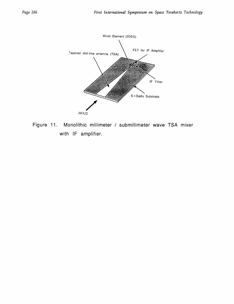
The nonlinearity of the resistance arises because increasing RF power heats theelectron gas above the lattice temperature; this in turn causes a change in electron mobility.This type of nonlinearity was first utilized in the InSb "hot-electron" detector and mixer.Its main disadvantage has always been the slow response time of the electrons in InSb,about 1 microsecond, which limits the IF frequency to 1 MHz. The response time of the2DEG is much faster, of the order of .1 to 1 nanoseconds, which should result in a mixerwith bandwidth in the range 1 — 10 GHz, as first pointed out by Smith et al. [8]. We arepresently fabricating elements of this type for use in mixers, which could be extended to theTHz region. A design in which a 2DEG element is integrated with a TSA antenna isshown in Figure 11. The original proposal for a 2DEG mixer by Smith et al., was for aliquid-helium temperture device, tuned to cyclotron resonance by a magnetic field. Wehave also shown that a nonlinear device at temperatures of 50-80 Kelvin, wihtout a
Page 180 First International Symposium on Space Terahertz Technology
magnetic field, should be feasible [Yngvesson, Lau and Yang, to be published]. It is alsoclear that the nonlinearity could be employed for harmonic generation, as well as mixing.
CONCLUSION
We have shown in this paper that TSA antenna arrays can be used with highefficiency in focal plane imaging as well as power-combining systems. The prototypesystems so far have operated in the 30-100 GHz range. It appears entirely feasible toextend these prototypes to the THz range, however, and much of the interesting work inthe area of integrated TSA arrays in the next few years is likely to be concentrated on suchefforts.
References
[1] P.J. Gibson, "The Vivaldi Aerial," in Proc. 9th European Microwave Conf.(Brighton, U.K.), 1979, pp. 101-105.
[2] R. Janaswamy, D.H. Schaubert, and D.M. Pozar, "Analysis of the TransverseElectromagnetic Mode Linearly Tapered Slot Antenna," Radio Sci., vol. 21, pp. 797—804, 1986.
[3] R. Janaswamy and D.H. Schaubert, "Analysis of the Tapered Slot Antenna," IEEETrans. Antennas Propagat., vol. AP-35, p. 1058-1065, 1987.
[4] J.F. Johansson, "A Moment Method Analysis of Linearly Tapered Slot Antennas,"IEEE Antennas and Propagat. Symposium, pp. 383-386, 1989.
[5] K.S. Yngvesson et al, "The Tapered Slot Antenna A New Integrated Element forMillimeter Wave Applications," IEEE Trans. Microw. Theory Techn., MTT-37,365-374, 1989.
[6] J.F. Johansson, E.L. Kollberg, and K.S. Yngvesson, "Model Experiments with SlotAntenna Arrays for Imaging," SPIE Proceedings, Vol. 598, pp. 118-125, 1985.
[71 K. C. Lee, et a. "Schottky Bather Diode on a Submicron—Thick Silicon MembraneUsing a Dual Surface Fabrication Technique," J. Appl. Phys. 60, 4038-4040, 1986.
[8] S.M. Smith, et al., "Millimeter and Submillimeter Detection Using Gai_xAlxAs/GaAsHeterostructures," Int. J. of Infr. and MMW, Vol. 8, No. 8, 793-802, 1987.
First International Symposium on Space Terahertz Technology Page 181
IE-PLANE
E---) H-PLANE
EIS (11.3= =
21 11
52 42 32. = = =
C1!) [:23 C!]
55
22 12=
23 13= =
24 . 1444 34= = =3 =3
SPACING (d)
FIN-LINE
TRANSITION
LENGTH
)
OPENING ANGLE 2
Vivaldi LTSA CWSA
Figurel The three different types of end-fire tapered slot antennas (TSA)
Figure 2. A typical TSA array with a fin-line to waveguide feeding block.The metal pattern made on one of the substrates is shown tothe right.
Metal pads
Silicon substrate
(a)
Silicon support frame
Silicon membranes as TSA substrate
(b)
Page 182 First International Symposium on Space Terahertz Technology
Figure 3. Schematic diagram of 94 GHz seven-element imaging system.
Figure 4. Silicon membrane TSA. (a) Metal pattern side; (b) Membrane side.

PARABOLOID
GRATINGLOBES
(
PARABOLOID
\\
CIRCULARPOLARIZER
ARRAY ANDAMPLIFYINGmODUF_S
'N THETA= 0: HI- C
- THETA = 10: PHI = 0 N,THETA=10: PHI=45
.2 4 .6 .8 1 1.2 1.4 1.6 1.8 2
CD
CD
CD•••■••
100
96
92
88
84
BO
76
72
68
64
60
First International Symposium on Space Teraher z Technology Page 183
Figure 5. Overview of near-field Cassegrain reflector system with power-combining array.
SPACING ( d/X
Figure 6. Calculated area efficiency of 21 element array, employing
elements with (cos , as a function of element spacing
d 0 ). The value q has been chosen to result in maximum
allowed directive gain for each element, based on its area.
-40B #
-90 -45 45
-313de
Page 184 First International Symposium on Space Terahertz Technology
Figure 7. Slot-line to microstrip transition used in TSA array.
ANGLE IN DEGREES
Figure 8. Measured E-plane radiation pattern for a 21-element array.
pin Powercombiningarray
pout
Scalarfeed, etc.
Lens Amplifying modules. Lens
(a) (b)
r AVA IrArAir.Metal Electrodes CbAs Cep
1111=11114
aradrigall===trArArd
Si. GaAs Substrate
Ohmic COfd
First International Symposium on Space Terahertz Technology Page 185
Possibly otherquasi-opticalcomponents
Figure 9. Schematic diagram of a focussing power combining quasi-
optical system.
Figure 10. Schematic diagram of a 2DEG device element. (a) overview;
(b) cross section.
Tapered slot-line antenna (ISA)FET for IF Amplifier
IF Filter
S.I.GaAs Substrate
Page 186 First International Symposium on Space Terahertz Technology
Mixer Element (2DEG)
RF/LO
Figure 11. Monolithic millimeter / submillimeter wave TSA mixer
with IF amplifier.