integrated voice and data network
TRANSCRIPT
COMMONWEALTH OF VIRGINIA SECTION 11 STATEWIDE AGENCIES RADIO SYSTEM (STARS) INTEGRATED VOICE AND DATA NETWORK
Integrated Voice and Data Network
11.O FUNCTIONAL SYSTEM DESCRIPTION
11.1 INTRODUCTION Motorola is providing an ASTRO®25 VHF Integrated Voice and Data (IV&D) Trunking system that is designed to meet the RF voice and 9600 bps data communications needs of the Commonwealth of Virginia. Motorola’s communications solution will provide mobile coverage throughout the Commonwealth as predicted by the RF coverage maps. Motorola’s solution will also interface with designated conventional (non-trunked) and Trunked radio systems located in the Commonwealth via the console subsystem. Finally, the system will use an integrated infrastructure for voice subscribers and for 9600 bps data subscribers.
11.2 ASTRO 25 TECHNOLOGY OVERVIEW Project 25 is a Standard developed by APCO (Association of Public Safety Communications Officials) primarily for the North American market. The Standard defines the Trunking and Common Air Interface (CAI) parameters for public safety systems, allowing competing manufacturers to offer interoperability with Project 25 CAI subscribers. Motorola’s Project 25 product is called ASTRO 25 which is a fully digital system solution. ASTRO 25 complies with all the mandatory requirements and features contained within the APCO 25 open standards (listed below) accepted today as Project 25, which allows manufacturers flexibility in how they implement the architecture of their systems. It is important to note that within Project 25 some features must be supported both by the system’s Infrastructure and by the subscriber units (radios). Thus, ASTRO 25 supports interoperability with Project 25 compliant radios from other manufacturers. The system utilizes narrowband (12.5 kHz) RF channel operation. (See Appendix 7 for further ASTRO 25 details highlighting some of the features.)
Page 1
SECTION 11 COMMONWEALTH OF VIRGINIA INTEGRATED VOICE AND DATA NETWORK INTEGRATED VOICE AND DATA NETWORK
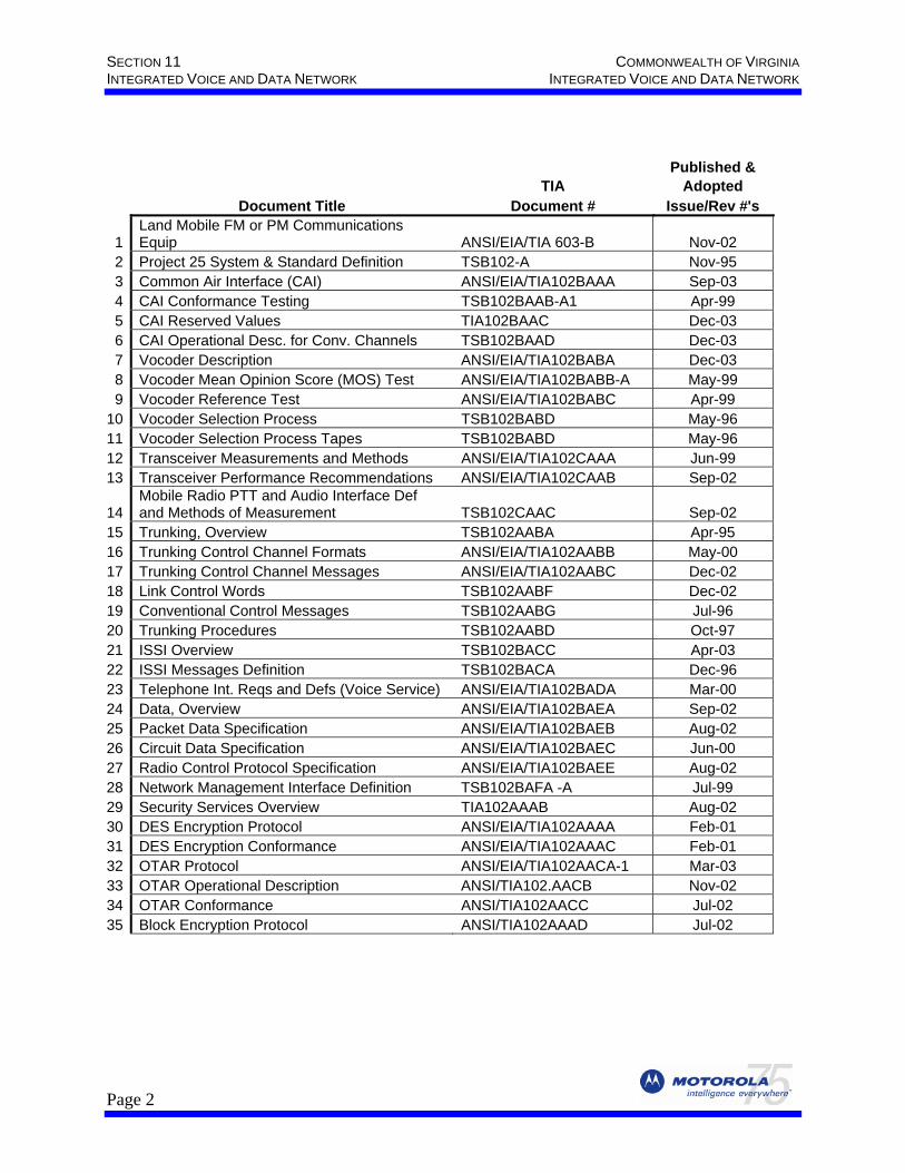
Published & TIA Adopted
Document Title Document # Issue/Rev #'s
1 Land Mobile FM or PM Communications Equip ANSI/EIA/TIA 603-B Nov-02
2 Project 25 System & Standard Definition TSB102-A Nov-95 3 Common Air Interface (CAI) ANSI/EIA/TIA102BAAA Sep-03 4 CAI Conformance Testing TSB102BAAB-A1 Apr-99 5 CAI Reserved Values TIA102BAAC Dec-03 6 CAI Operational Desc. for Conv. Channels TSB102BAAD Dec-03 7 Vocoder Description ANSI/EIA/TIA102BABA Dec-03 8 Vocoder Mean Opinion Score (MOS) Test ANSI/EIA/TIA102BABB-A May-99 9 Vocoder Reference Test ANSI/EIA/TIA102BABC Apr-99
10 Vocoder Selection Process TSB102BABD May-96 11 Vocoder Selection Process Tapes TSB102BABD May-96 12 Transceiver Measurements and Methods ANSI/EIA/TIA102CAAA Jun-99 13 Transceiver Performance Recommendations ANSI/EIA/TIA102CAAB Sep-02
14 Mobile Radio PTT and Audio Interface Def and Methods of Measurement TSB102CAAC Sep-02
15 Trunking, Overview TSB102AABA Apr-95 16 Trunking Control Channel Formats ANSI/EIA/TIA102AABB May-00 17 Trunking Control Channel Messages ANSI/EIA/TIA102AABC Dec-02 18 Link Control Words TSB102AABF Dec-02 19 Conventional Control Messages TSB102AABG Jul-96 20 Trunking Procedures TSB102AABD Oct-97 21 ISSI Overview TSB102BACC Apr-03 22 ISSI Messages Definition TSB102BACA Dec-96 23 Telephone Int. Reqs and Defs (Voice Service) ANSI/EIA/TIA102BADA Mar-00 24 Data, Overview ANSI/EIA/TIA102BAEA Sep-02 25 Packet Data Specification ANSI/EIA/TIA102BAEB Aug-02 26 Circuit Data Specification ANSI/EIA/TIA102BAEC Jun-00 27 Radio Control Protocol Specification ANSI/EIA/TIA102BAEE Aug-02 28 Network Management Interface Definition TSB102BAFA -A Jul-99 29 Security Services Overview TIA102AAAB Aug-02 30 DES Encryption Protocol ANSI/EIA/TIA102AAAA Feb-01 31 DES Encryption Conformance ANSI/EIA/TIA102AAAC Feb-01 32 OTAR Protocol ANSI/EIA/TIA102AACA-1 Mar-03 33 OTAR Operational Description ANSI/TIA102.AACB Nov-02 34 OTAR Conformance ANSI/TIA102AACC Jul-02 35 Block Encryption Protocol ANSI/TIA102AAAD Jul-02
Page 2
COMMONWEALTH OF VIRGINIA SECTION 11 STATEWIDE AGENCIES RADIO SYSTEM (STARS) INTEGRATED VOICE AND DATA NETWORK
11.2.1. Packet-based Architecture With ASTRO 25, Motorola will provide the Commonwealth a trunked radio system operating on a packet-based architecture. The term “packet-based” primarily references the capability of transporting digitized voice and data via packets through the system infrastructure, allowing the integration of voice and data onto a single infrastructure platform. The Internet Protocol (IP) standard is utilized to establish a connection between system components.
11.2.2. Centralized System Management The ASTRO 25 system’s operation and management is performed through these features: System-wide Clock Setting, Centralized Software Downloads, and a network management user interface based on the Microsoft Windows® environment. The centralized system management keeps the system healthy with current alerts, diagnostics and faults reported at a centralized location. The ASTRO 25 system uses a system-wide clock setting to keep key devices on the system at the same time to improve fault diagnostics and call activity tracking. The ASTRO 25 network management system will provide functionality to remotely distribute software upgrades to the ASTRO 25 Repeaters and PSC 9600 Site Controllers on the network.
11.2.3. Wide Area Communications The basic building blocks of the ASTRO 25 system are:
• System Level - composed of multiple ‘ASTRO 25 zones’ • Zone Level - composed of multiple sites • Site Level - ASTRO 25 Repeater sites and routing equipment • User Level - portables and mobiles
The Statewide Agencies Radio System (STARS) ASTRO 25 system will provide communications across two zones and will allow users from different zones to be combined into talkgroups. This means that a STARS user can communicate across a wide geographic area and utilize a wide range of communications capabilities. A STARS user at any location within the coverage area can, with the proper authorization, press the radios push-to-talk (PTT) button to make a call to any valid talkgroup or individual located anywhere else in the coverage area. Motorola uses the term ‘ASTRO 25 zone’ to describe a particular group of RF sites, dispatch sites, and network management equipment that interfaces directly to a particular Master Site. Each ASTRO 25 zone operates under the command of its respective Master Site (this terminology should not be confused with the Virginia State Police (VSP) ‘Communications Channel or Zone’ terminology). Multiple VSP ‘Communications Channels or Zones’ may fall within an ASTRO 25 ‘zone’, and thus are controlled by the same Master Site. Motorola will provide a system comprising two ASTRO 25 zones to the Commonwealth.
Page 3
SECTION 11 COMMONWEALTH OF VIRGINIA INTEGRATED VOICE AND DATA NETWORK INTEGRATED VOICE AND DATA NETWORK
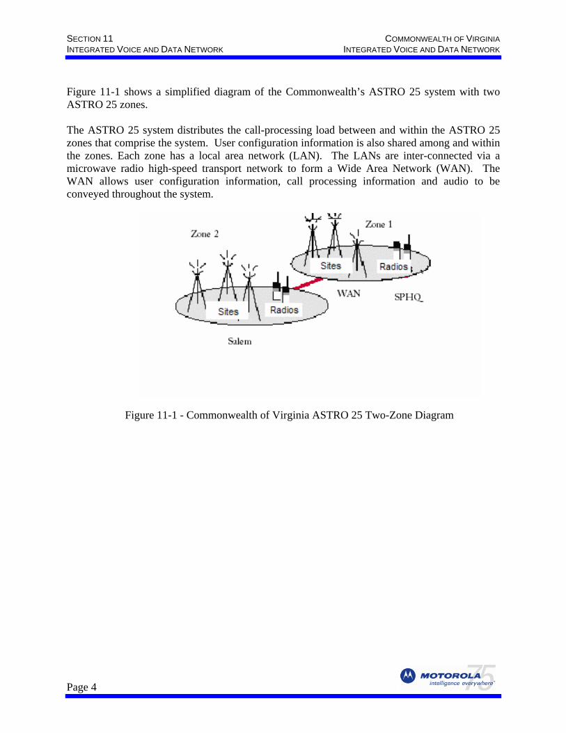
Figure 11-1 shows a simplified diagram of the Commonwealth’s ASTRO 25 system with two ASTRO 25 zones. The ASTRO 25 system distributes the call-processing load between and within the ASTRO 25 zones that comprise the system. User configuration information is also shared among and within the zones. Each zone has a local area network (LAN). The LANs are inter-connected via a microwave radio high-speed transport network to form a Wide Area Network (WAN). The WAN allows user configuration information, call processing information and audio to be conveyed throughout the system.
Figure 11-1 - Commonwealth of Virginia ASTRO 25 Two-Zone Diagram
Page 4
COMMONWEALTH OF VIRGINIA SECTION 11 STATEWIDE AGENCIES RADIO SYSTEM (STARS) INTEGRATED VOICE AND DATA NETWORK
11.3 INFRASTRUCTURE COMPONENTS AND FEATURES
11.3.1. General The ASTRO 25 VHF Integrated Voice and Data (IV&D) trunking system provides the Commonwealth with the most current technology and system design. Motorola’s commitment to constant innovation and improvement means that the technology used in this system will be improved upon during the multi-year implementation schedule. This necessitates that some of the equipment described below that is used in the earlier implementations may be supplemented with equipment that is developed later in the project, at no additional charge to the Commonwealth or with our consent. Therefore certain system features or functions that rely on capabilities or equipment not yet developed or available will not impact voice and data systems already in operation. .
11.3.2. Master Site [CONFIDENTIAL/PROPRIETARY Information – EXEMPT from public disclosure]
11.3.3. Master Site Equipment (See Appendix 5 for detailed product literature.) 11.3.3.1. The ASTRO 25 Wide Area Network (WAN) Switch The Master Site hardware interface, for the remote site equipment, is a Wide Area Network (WAN) switch. The WAN Switch is a chassis-based device with redundant power supplies, redundant CPUs, network management, and back plane switching; all which increase availability. The switch will have 1:1 redundant cards and monitor itself for module failures. If a card failure is detected, it automatically switches to the back up card and sends out an alarm to the NOC. The WAN switch, used with its network management system, provides a proactive management system as well as a means of receiving and reporting failure alarms, which also increases the WAN switch's availability.
11.3.3.2. Local Area Network (LAN) Switch The Master Site equipment includes an Enterprise Ethernet Switch, or Local Area Network (LAN) switch. The LAN switch is a chassis based device with redundant power supplies, redundant CPUs, and redundant Layer 2 port cards. The LAN switch aggregates all the Ethernet interfaces for all servers, clients, and routers at the Master Site.
11.3.3.3. Core Routers The Core Routers perform the routing control of audio, data, and network management traffic in and out of the zone, replicating packets while achieving the fast access levels required by real-
Page 5
SECTION 11 COMMONWEALTH OF VIRGINIA INTEGRATED VOICE AND DATA NETWORK INTEGRATED VOICE AND DATA NETWORK
time voice systems. To increase availability, redundant Core Routers are used. If the path through the primary router is lost, the redundant router takes over. One-to-one Core Router redundancy increases system availability. The number of Core Routers is dependent upon the number of channels in the system. The Master Site audio, data, control, and network management equipment interfaces to the remote ASTRO 25 repeater sites and dispatch sites, via the WAN switch, through the core routers. In the provided system, each Master Site utilizes two (redundant configuration) core routers to handle the ASTRO 25 repeater sites and Dispatch locations associated with the respective zone.
11.3.3.4. Gateway Routers Gateway Routers are used for devices that forward packets beyond their local LAN. To provide increased availability, Gateway Routers are provided in a redundant configuration. For the Commonwealth’s system, each Master Site uses two Gateway Routers.
11.3.3.5. MZC3000 Zone Controller System call processing and mobility management are provided by the MZC3000 Zone Controller, which is the heart of the wide-area communications system. The MZC3000 is provided in a redundant configuration, at each Master Site, providing the Commonwealth with the reliability required for mission critical communications. The MZC3000 interfaces via Ethernet to the Ethernet LAN switch, and provides access to the packet switched network via the Gateway Routers. The Motorola MZC3000 Zone Controller incorporates Compact Peripheral Component Interconnect (cPCI) hardware, which provides adaptability to technology enhancements, and better planning of future communications needs. The system as designed is configured with sufficient licenses to accommodate up to a total of 56 ASTRO 25 Repeater Sites (includes capacity for the use of a 700/800 MHz 5-channel Transportable Site and a VHF Disaster Recovery Transportable Communication Site (DRTCS)), and up to twenty-thousand user ID’s to meet the current needs of the Commonwealth.
11.3.3.6. Ambassador Electronics Bank (AEB) The Ambassador Electronics Bank (AEB) is a large capacity Time Division Multiplex (TDM) audio-processing switch that provides an audio and call control interface between the CENTRACOM Gold Series Elite operator positions, located at the dispatch centers, and the wide-area trunking system. The AEB utilizes Ambassador (AMB) cards for interface to the Motorola Gold Elite Gateway (MGEG) and the Central Electronics Bank (CEB). One AEB will be located at each Master Site.
11.3.3.7. Motorola Gold Elite Gateway (MGEG) Because audio is transported over an IP based network in the ASTRO 25 system, and the CENTRACOM Gold Series dispatch equipment uses a circuit-switched architecture, a Motorola Gold Elite Gateway (MGEG) is provided. The MGEG acts as the “bridge” between the IP packet-switched system and the circuit switched transport of the CENTRACOM Gold Series system. At each Master Site, there are two physical MGEG devices in a load-sharing configuration that are connected to both the LAN switch and the redundant AMB cards in the
Page 6
COMMONWEALTH OF VIRGINIA SECTION 11 STATEWIDE AGENCIES RADIO SYSTEM (STARS) INTEGRATED VOICE AND DATA NETWORK
AEB. The MGEG runs on Microsoft’s Windows operating system. The MGEG hardware unit is the industry-standard cPCI PC. Each MGEG uses the Gateway Routers to multicast its data beyond the local LAN into the WAN. For the STARS implementation, there are two (redundant configuration) MGEG devices and four AMB cards that interface with these devices at each Master Site.
11.3.3.8. Elite Database Server The Elite Database Server is a Windows based server located at the Master Site. This server holds configuration information for all the Dispatch Consoles in a particular zone; it also holds a database of the text aliases used within the dispatch console system in the respective zone. One Elite Database Server is located at each Master Site. These two databases are managed using two software applications:
• Console Database Manager (CDM) • Alias Database Manager (ADM)
These applications reside and run on the Database Server. The Console Database Manager enables a supervisor to generate a personality for each dispatch operator position and store these configuration details at a central point for ease of maintenance. The Alias Database Manager provides for text aliasing of radio identities and status message values within the dispatch system and management of these aliases from a single point. When the Elite Dispatch application is started on the Dispatch operator position, it checks the version of the configuration and alias files on the Elite Database Server and compares them with the locally stored versions. If the configuration file version is different, the Dispatch operator can choose to download the latest file from the server which then downloads the new configuration information to the CEB. If the alias file is different the Dispatch operator position downloads the latest file from the server. The Dispatch operator position checks with the server every five minutes to determine if a new alias list should be downloaded via the LAN. Once downloaded, each Dispatch operator position operates independently from the server. In the event that the LAN connectivity is lost between the dispatch site and the Master Site, the consoles continue to operate unaffected using the latest downloaded information. During the configuration download, critical communications on the selected channel can continue uninterrupted using the backup control station provided at each Dispatch position. The Elite architecture allows different dispatching shifts to use different screen configurations (if so desired), depending upon their dispatch requirements. In the event that a dispatch center is inaccessible, due to an evacuation, etc., the inaccessible dispatch site’s screen configuration(s) can be loaded at any other dispatch location, within the same zone (Master Site), allowing dispatcher’s to move from location to location and continue to use their familiar console screen interface.
11.3.3.9. Packet Data Gateway (PDG) The ASTRO 25 VHF IV&D system utilizes a Packet Data Gateway (PDG) to manage the data messaging in the IV&D trunked system. The PDG is a modular platform designed to link wire
Page 7
SECTION 11 COMMONWEALTH OF VIRGINIA INTEGRATED VOICE AND DATA NETWORK INTEGRATED VOICE AND DATA NETWORK
line Internet Protocol (IP) customer data networks to Motorola’s ASTRO 25 IV&D) network. The PDG supports the Common Air Interface (CAI) protocol for Motorola’s ASTRO 25 network, and complies with the Project 25 packet data specifications for radio-to-Fixed Network Equipment (FNE) data configurations. FNE is all equipment that is normally ‘fixed’ at some location. The PDG allows data users to roam seamlessly throughout the coverage area within an ASTRO 25 network without the need to manually select a different channel or have any specific knowledge of the network. The PDG utilizes cPCI hardware and utilizes the Gateway Routers to multicast its data beyond the local LAN into the WAN. The PDG is provided in a non-redundant configuration and PDG spares are provided in the event of an equipment failure.
Page 8
COMMONWEALTH OF VIRGINIA SECTION 11 STATEWIDE AGENCIES RADIO SYSTEM (STARS) INTEGRATED VOICE AND DATA NETWORK
11.3.3.10. Gateway GPRS Support Node (GGSN) The ASTRO 25 VHF IV&D system utilizes a Gateway GPRS Support Node (GGSN) to provide the routing and address resolution services needed to route data messages between the Commonwealth’s customer enterprise network (CEN) and the IV&D Network. The GGSN provides the interface that translates data formats, and signaling protocols for inter-network communications while simultaneously isolating the different networks IP domains. One GGSN is provided in the ASTRO 25 IV&D system and will be located at the SPHQ Master Site in Richmond. The Commonwealth will provide a Category 5 interface no more than 15 feet from the GGSN in the Master Site equipment room at this location into the CEN.
11.3.3.11. Network Time Protocol Server (NTP) A Network Time Protocol (NTP) Stratum 1 server is required at each Master Site to provide a time and date reference to all IP-connected system elements (NTP clients) that support the Network Time Protocol (NTP). If the primary NTP server is unreachable, a secondary or backup NTP server can be configured to support NTP client time synchronization. In the absence of the primary (Stratum1) NTP server, the Zone Database Server (described later in this section) is designated as the secondary NTP server. The time distributed by the NTP Stratum 1 server to system devices is referenced to Universal Time Coordinated (UTC). Distribution is achieved using the Network Time Protocol. The NTP server also provides clocking synchronization to the AEB and WAN links. There are then two branches; one from the AEB and the other from the WAN switch. The AEB supplies clock to the CEB, PBX and MGEG. The WAN switch supplies clock to the RF and Dispatch sites.
11.3.3.12. ASTRO 25 Network Management System
11.3.3.12.1. Network Management System Hardware The ASTRO 25 Network Management System is comprised of a variety of hardware components, databases, and software applications that are used to perform Configuration Management, Performance Management, Fault Management, Security Management, and Accounting Management. The network management system implementation is based on a client / server architecture that resides within the system network. The following servers, located at the Master Site, are utilized to provide the network management features for the provided ASTRO 25 system: User Configuration Server (UCS), Zone Database Server (ZDS), Zone Statistics Server (ZSS), Air Traffic Router (ATR) Server, FullVision Server (FVS), Ethernet Switch Management Server (ESMS), and the WAN Switch Management Server (WSMS). These servers utilize the cPCI design. Additionally, the Transport Network Management Server (TNMS) will be provided. These servers will be used in conjunction with the eleven provided network management clients and one Transport Network Management Client for Commonwealth administrative personnel to properly manage the ASTRO 25 system.
Page 9
SECTION 11 COMMONWEALTH OF VIRGINIA INTEGRATED VOICE AND DATA NETWORK INTEGRATED VOICE AND DATA NETWORK
11.3.3.12.2. User Configuration Server (UCS) The User Configuration Server (UCS) allows the person serving as the System Administrator to configure subscriber, talkgroup, and security information at a system level. The UCS provides a single point of entry for system-wide configuration parameters. Changes to the UCS automatically propagate throughout the system. The UCS is accessible by any properly authorized user from any network management client in the system. The user configurable parameters are automatically downloaded to the appropriate zone controllers after each new entry is updated. The User Configuration Server (UCS) uses a cPCI chassis with Sun Solaris OS 7. One UCS is required for the entire system, and it will be located at the Network Operations Center (NOC) collocated with the Zone 1 Master Site located at the State Police Headquarters.
11.3.3.12.3. Systemwide Statistics Server (SSS) One Systemwide Statistics Server (SSS) will be used for the entire system, and it will be located at the NOC near the Zone 1 Master Site in Richmond. System-wide statistics such as the number of Calls, Push-To-Talks, and Busies are accumulated over preset time intervals. For the Commonwealth, data will be accumulated over a one-hour interval and retained for up to ten days, or data can be accumulated monthly and retained for one year, depending upon the amount of system activity information gathered and the amount of storage media space available. The SSS resides in the same cPCI chassis as the UCS and they share a common CD-ROM drive. A Digital Audio Tape (DAT) drive is included with the SSS and it is used for data backup.
11.3.3.12.4. Transport Network Management Server (TNMS) One Transport Network Management Server (TNMS) will be provided for the entire system, and it will be located at the SPHQ Master Site. This server will provide the ability to monitor the performance of various Transport Network devices via the InfoVista application and will send Motorola defined performance threshold traps to the FullVision fault management application (described later in this section). One Personal Computer (PC) TNM client is provided to the Commonwealth and will be located at the SPHQ NOC collocated with the Master Site. The TNM client PC operates under the Windows operating system.
11.3.3.12.5. Zone Database Server (ZDS) User configuration information entered into the UCS is replicated to the ZDS in each zone. The ZDS is responsible for transferring the necessary configuration information to the zone controller within the zone. This transfer is called database export. This export occurs at regular or manual intervals. The zone controller uses the exported database to fulfill its mobility management and call processing duties. Communication between the ZDS and the UCS is not strictly one-way. The zone database server also updates the UCS database with site information. The Zone Database Server (ZDS) uses a cPCI chassis with Sun Solaris OS 7. One ZDS is required at each Master Site. The ZDS cPCI chassis has a shared CD-ROM drive and DAT drive which is used for data backup.
Page 10
COMMONWEALTH OF VIRGINIA SECTION 11 STATEWIDE AGENCIES RADIO SYSTEM (STARS) INTEGRATED VOICE AND DATA NETWORK
11.3.3.12.6. Zone Statistics Server (ZSS) This server provides data storage for statistics data. Each zone (Master Site) contains one ZSS for statistics that are stored locally. Statistics such as the number of Calls, Push-To-Talks, and Busies are accumulated over preset time intervals. For the Commonwealth, data will be accumulated over a one-hour interval and retained for up to ten days or data can be accumulated monthly and retained for one year, depending upon the amount of system activity information gathered and the amount of storage media space available. One ZSS is required at each Master Site and it resides in the same cPCI chassis as the ZDS.
11.3.3.12.7. Air Traffic Router (ATR) ServerThe ATR manages all non-call processing processes. The Radio Applications Programming Interface (RAPI) process is located on the Air Traffic Router (ATR) server that is collocated on the same Local Area Network as the Zone Controller. RAPI is the zone level interface protocol to the Zone Controller for call processing related operations such as radio control (Radio Control Management), mobility services (Radio Affiliation) and call logging (Air Traffic Information Access) information. RAPI broadcasts call logging information for use by some network management applications or other third party applications. The Zone Controller and ATR are connected by a TCP link. Having to support a simple interface allows the Zone Controller to focus on real-time call processing. One ATR is required at each Master Site and it resides in the same cPCI chassis as the ZDS.
11.3.3.12.8. FullVision Server (FVS) FullVision is a fault management tool that provides a single interface for monitoring alarms and alerts generated by the radio system infrastructure and the LAN/WAN equipment. The FullVision Integrated Network Manager (INM) is based on Hewlett-Packard’s OpenView™ Network Node Manager (NNM) software application. Hewlett-Packard’s OpenView™ is a standard network management software application that uses Simple Network Management Protocol (SNMP) over Internet Protocol (IP) to communicate with the elements it manages. One FullVision server is provided at each Master Site and it resides in the same cPCI chassis as the ZDS.
11.3.3.12.9. Ethernet Switch Management Server (ESMS) The Ethernet Switch Management Server (ESMS) hosts the Routed WAN (RWAN) Management Solution. The RWAN suite is a collection of powerful enterprise management applications to configure, administer, monitor and troubleshoot the Ethernet Switch. Although located in a dedicated chassis separate from the other network management system servers, the ESMS hardware is also cPCI-based and runs the Solaris 7 OS. The ESMS has its own hard disk drive, CD-ROM and DAT drive which is used for data backup. One ESMS is provided for the entire system and it is located at the Zone 1 Master Site at SPHQ in Richmond.
Page 11
SECTION 11 COMMONWEALTH OF VIRGINIA INTEGRATED VOICE AND DATA NETWORK INTEGRATED VOICE AND DATA NETWORK
11.3.3.12.10. WAN Switch Management Server (WSMS) The WAN Switch Management Server (WSMS) hosts the Multi-service Data Manager, a collection of powerful enterprise management applications to configure, administer, monitor and troubleshoot the WAN Switch. Although separate from the other network management system servers, the WSMS hardware is also cPCI-based and runs the Solaris 7 OS. The WSMS has its own hard disk drive, CD-ROM, and DAT drive which is used for data backup. One WSMS is provided for the entire system and it is located at the Zone 1 Master Site at SPHQ in Richmond.
11.3.3.13. Network Management System Applications
11.3.3.13.1. IV&D Network Management IV&D Network Management describes the processes that allow a management user to create, change, delete, and list the objects that make up the ASTRO 25 system. An object is a representation of a system device (such as an ASTRO 25 repeater site repeater) or device connectivity. Objects also include the radios, radio users, talkgroups or multi-groups. The ASTRO 25 system’s managed objects are configured using two applications:
• User Configuration Manager (UCM) at the Zone 1 Master Site. • Zone Configuration Manager (ZCM) at both Master Sites.
11.3.3.13.1.1. User Configuration Manager The UCM application maintains the system-wide configuration information for radios, users, talkgroups and inter-zone communications. This also includes security information. The UCM application may be accessed from ASTRO 25 network management client workstations by properly authorized management users. The subscriber profiles feature allows the replication of parameters that are common to multiple radio units, thereby reducing the time and effort to load the user configuration database. Working in concert with the User Configuration Server (UCS), radio unit data is entered only once for each unit, and automatically distributed to the user configuration database residing in the Zone Database Server (ZDS). A centralized Software Download (SWDL) feature is also included. This feature provides a means for downloading software to select remotely located infrastructure equipment on the network without otherwise having to travel, or visit, the site to locally install software upgrades or enhancements. The UCM is responsible for distributing all system-wide configuration information.
Page 12
COMMONWEALTH OF VIRGINIA SECTION 11 STATEWIDE AGENCIES RADIO SYSTEM (STARS) INTEGRATED VOICE AND DATA NETWORK
11.3.3.13.1.2. Zone Configuration Manager The Zone Configuration Manager (ZCM) application is used at the zone level to maintain configuration information for the FNE. The ZCM application is used to enter configuration information for infrastructure objects within a zone. The ZCM Main Window is divided into two areas: the Navigation Pane and the Contents Pane. The Navigation Pane displays icons for each of the configurable objects in a logical hierarchy. The Contents Pane displays any records associated with an object selected in the Navigation Pane. User configuration information entered into the UCS is replicated in the Zone Database Server. The Zone Database Server is responsible for transferring the necessary configuration information to the zone controller. This transfer is called a database export. This export occurs at regular intervals but can also be done manually and as a response to changes to the database. The zone controller uses the exported database to fulfill its mobility management and call processing duties. Communication between the ZDS and the UCS is not strictly one way. The Zone Database Server also updates the UCS database with site information.
11.3.3.13.2. Performance Management The following Performance Management tools are used to monitor, collect, log and evaluate network performance and resource utilization data. Radio resource metrics and packet transport network metrics are collected and reported separately. The network management system collects statistics of radio resource usage in the Zone and System Statistics Servers for radio units, talkgroups, channels, sites, zones and system-wide activity report generation. ZoneWatch, and other applications supplied, either display real-time communications activity or collect traffic statistics over predetermined intervals for report generation (i.e., Dynamic and Historical Reports). Historical statistics are aggregated into detailed and summarized reports on both an individual zone and system-wide basis. Statistics are available on a per hour basis by system, zone, site, channel and user. Other statistics that are useful in troubleshooting, sizing and monitoring the system are also collected. Statistics are summarized by hour and available by hour for the prior 10 days; by day for the past 62 days; and by month for up to a year, depending upon the amount of system activity information gathered. The network management system also has archive and export features for saving reports or analyzing data offline.
11.3.3.13.2.1. Zone Historical Reports Application This application produces reports on radio infrastructure and radio resource usage within an identified zone. A pre-defined set of reports, with field selection capability, is supplied to produce “standard” or tailored reports. In addition, the Commonwealth may generate custom reports via the Custom Reports Generation application that is provided. Historical Reports are generated automatically or on demand. Automatic reports are produced at a specific scheduled time and date or on a recurring time and date interval. Reports can be sent to the monitor screen, a printer or Hyper Text Markup Language (HTML) or Comma Separated Value (CSV) files.
Page 13
SECTION 11 COMMONWEALTH OF VIRGINIA INTEGRATED VOICE AND DATA NETWORK INTEGRATED VOICE AND DATA NETWORK
11.3.3.13.2.2. System-wide Historical Reports The System-wide Historical Reports application is provided with the network management system. Radio traffic statistics from multiple zones, including inter-zone traffic, are accumulated in the System Statistics Server and collated to produce system-wide reports.
11.3.3.13.2.3. Dynamic Reports Dynamic Reports are intended for short term monitoring. Report intervals may be set for 15 seconds, one minute or 15 minutes, and up to 100 intervals can be collected. Multiple objects and up to 12 statistics can be included in a single report. As with the Historical Reports, a complete set of pre-defined Dynamic Reports is provided. Reports can be output to the client PC workstation display, a printer or file. This display provides zone-level, real-time line charts or 3-D bar graphs that illustrate channel utilization for all call types – group, private, phone interconnect, and control channel.
11.3.3.13.2.4. Air Traffic Information Access (ATIA) Data This interface provides the raw air traffic data for intra-zone calls. With the provided billing system, the ATIA feature allows the Commonwealth to generate billing information to charge individual departments or agencies for their use of the system.
11.3.3.13.2.5. ZoneWatch ZoneWatch is a performance management tool having customizable displays and grids to monitor real-time communications activity occurring in a single zone. The information displayed can help system managers be proactive in making better resource planning decisions, such as when additional channels need to be added to busier sites.
11.3.3.13.2.6. ZoneWatch Grid Screen Air traffic within a single zone is displayed on a Site/Channel grid. Real-time call activity for each channel is displayed in its respective cell.
11.3.3.13.2.7. ZoneWatch Control Display The ZoneWatch Control Display presents call activity messages that can be used to isolate errors, trace the progress of a call and troubleshoots or analyzes current system activity. It also provides information about activity occurring on the control channel, such as rejects, and emergency alarms.
11.3.3.13.2.8. Affiliation Display Upon initial power-up and as mobile users move across a geographic area covered by one radio site to another, ASTRO 25 mobile and portable radios affiliate to the zone and site now providing the radio service. The responsibility for providing radio service to the unit is thus “handed-off” to another zone and/or site. This mobility management function allows the Zone Controller to have knowledge of the site currently serving the unit, such that the unit can be immediately connected or included in private or group dispatch calls without having to broadcast to all sites.
Page 14
COMMONWEALTH OF VIRGINIA SECTION 11 STATEWIDE AGENCIES RADIO SYSTEM (STARS) INTEGRATED VOICE AND DATA NETWORK
The Affiliation Display provides a dynamic view of the sites to which all operating units are currently affiliated, to the details of zone, site and talkgroup. This feature allows the system manager to track and troubleshoot radios in the system. Affiliation Display suggests the area in which the unit may currently be operating based on the unit’s last affiliation and the site’s radio coverage. The focus of the Affiliation Display can be on an individual site, a specific talkgroup or an individual radio. This information can be displayed in both text and graphic formats.
11.3.3.13.3. Accounting Management The ASTRO 25 network management system provides a licensed interface for Salem and SPHQ, Air Traffic Information Access (ATIA), to which third-party applications can interface for the purpose of collecting individual radio unit and talkgroup traffic data as input to the external accounting or billing package. Motorola will provide an Accounting Management hardware/software package that uses the ASTRO 25 system ATIA data stream to provide airtime usage information for accounting purposes. The Accounting Management package will be able to capture all pertinent information about each call including Talkgroup, ID, Site, Type, Date, Time, Length, and number dialed (telephone interconnect calls). The gathered information can be used for creating billing reports, traffic reports, etc. The ATR provides one-way, unconfirmed information as an ATIA data stream to the Accounting Management application.
11.3.3.13.1. ATIA Logger and Log Viewer The ATIA Logger records one day’s worth of ATIA packets and stores them on the Air Traffic Router. The log may be viewed on a network management client PC workstation.
11.3.3.13.4. Security Management Security Management controls or limits access to applications, certain features and configuration data according to definable access privileges. All users must identify themselves to the network management system at log-on by entering a name/ID and a password. The network management system Security Partitioning feature allows the granting or restricting of access by department, location, user type, application and function.
11.3.3.13.4.1. User Client Security User Client Security provides the first level of security by denying access to all network management applications unless the user enters a valid log-on name/ID and the corresponding password.
Page 15
SECTION 11 COMMONWEALTH OF VIRGINIA INTEGRATED VOICE AND DATA NETWORK INTEGRATED VOICE AND DATA NETWORK
11.3.3.13.4.2. Security Partitioning Security Partitioning allows a system administrator to assign access privileges to specific applications. These applications include Configuration Manager, Radio Control Manager, Historical Reports and ZoneWatch. The system administrator can grant or restrict a user’s access to multiple zones.
11.3.3.13.4.3. Radio Control Manager (RCM) The RCM application provides two types of functions: radio commands that can be initiated (e.g., Dynamic Regrouping and Selective Inhibit) and radio events that are displayed (e.g., Status and Emergency Alarm). The RCM has the following features:
• A Graphical User Interface (GUI) for ease of use • RCM can be accessed via the network management client • Control functionality across multiple zones • On-line Help
11.3.3.13.4.4. Dynamic Regrouping User License This feature adds the ability for a RCM user to perform Dynamic (talkgroup) Regrouping for implementing storm plans, special events and the like. Each of the provided network management clients (see Tables 11-1 and 11-3) includes one user license for Dynamic Regrouping. Individual radio units, operating in different talkgroups, may have a unique need to communicate, requiring the group of individual radios to be consolidated into a temporary talkgroup. Dynamic Regrouping allows authorized personnel, using a network management client, to change individual radio talkgroup selections, creating a new talkgroup containing the users having the need to communicate. The Dynamic Regrouping command is initiated from the network management client, transmitted over the control channel, and is sent to the Zone Controller through the network management system. Dynamic Regrouping commands are easily deactivated by the network management client operators. Dynamic Regrouping Storm Plans represent any number of pre-programmed Dynamic Regrouping combinations constructed in advance to anticipate a unique need, such as a disaster, or to make a needed adjustment for an infrequent yet repeated event, like a parade or election. When implemented, a Storm Plan will construct a new talkgroup, containing the radios specified by the stored Dynamic Regrouping command. Storm Plans are de-activated as regular Dynamic Regrouping commands.
Page 16
COMMONWEALTH OF VIRGINIA SECTION 11 STATEWIDE AGENCIES RADIO SYSTEM (STARS) INTEGRATED VOICE AND DATA NETWORK
11.3.3.13.4.5. Computer Aided Dispatch Interface
The Computer Aided Dispatch Interface (CADI) (as specified in Appendix 10) provides the Virginia State Police (VSP) CAD system with access to select radio traffic information and some control functions to provide a method for the VSP CAD host to interface to the ASTRO 25 System. (2) The CADI supports traffic flow in both directions, inbound (CAD to the radio network) and outbound (radio network applications to CAD). Motorola will supply CADI data for both zones to the VSP CAD message switch at SPHQ. The radio traffic information supported by the CADI includes PTT IDs, Emergency IDs, Statuses, Call Alert messages sent from radio-to-radio and various radio acknowledgements. Alias updates to the CAD are not supported. The VSP CAD host must be able to handle the CADI information on-line as the CADI information is not buffered by the ASTRO 25 system. The control functions available are the initiation of individual Dynamic Regrouping and Cancel Regrouping commands, Radio Checks, Individual Selective Radio Inhibit and Cancel Inhibit commands, Selector Lock and Selector Unlock commands, and Zone Controller Status Query commands. The proper interface between the ASTRO 25 system CADI and the existing CAD system, and the operation of the CAD system, is the responsibility of the Commonwealth. Forty (40) hours of technical support is included with the ASTRO 25 CADI to assist the Commonwealth and their CAD vendor with this interface. Last paragraph removed – [CONFIDENTIAL/PROPRIETARY Information – EXEMPT from public disclosure]
Page 17
SECTION 11 COMMONWEALTH OF VIRGINIA INTEGRATED VOICE AND DATA NETWORK INTEGRATED VOICE AND DATA NETWORK
11.3.3.13.5. Fault Management
11.3.3.13.5.1. FullVision Integrated Network Manager (INM) Motorola’s FullVision Integrated Network Manager (INM) is the fault management application for the ASTRO 25 IV&D system. FullVision INM provides a centralized view of the operational status of the entire ASTRO 25 multizone system by displaying intuitive, graphical representations (i.e., sub-system topology maps) of the system. Problems are identified when they occur. Functions and tools provide the ability to notify support personnel, track, diagnose, and correct faults. FullVision INM also maintains a data warehouse, storing up to 30 days of event history for report generation. FullVision INM, integrated with Motorola’s Router Manager Application for the management of Motorola’s routers, serves as the fault detection and notification platform for the major infrastructure components in the system. An auto discovery feature finds and identifies the Motorola manufactured devices, including the Motorola Gold Elite Gateway (MGEG), Packet Data Gateway, the Motorola packet routers, and the following Motorola-approved third-party inter-networking equipment:
• WAN switch • LAN switch
Other essential infrastructure and site equipment status can be viewed on FullVision INM using the provided MOSCAD (Motorola SCADA – Supervisory Control and Data Acquisition) “plug-in.” The MOSCAD system (described in the Alarm and Control Subsystem section) is capable of monitoring a broad range of analog, digital and simple closure inputs. As such, environmental sensors, Uninterruptible Power Supplies (UPS), channel banks, microwave gear and Central Electronics Banks, that do not otherwise have connectivity to the packet transport network, will be monitored for fault conditions and reported to the FullVision INM via the MOSCAD Gateway. FullVision INM provides an SNMP trap message forwarding capability that is capable of passing fault information to a higher level, “Enterprise” network manager (not provided). Additionally, faults and interpretive messages will be forwarded to the appropriate service technician’s alphanumeric pager via a compatible commercial paging service. The paging feature requires the use of a dedicated Commonwealth-provided paging modem phone line, and an alphanumeric paging service that provides a modem bank to accept computer-generated paging requests.
11.3.3.13.6. ASTRO 25 Network Management Clients Eleven (11) Personal Computer (PC) network management (NM) clients are provided to the Commonwealth. One NM client is provided at each of the seven VSP Divisional Dispatch Centers, the VSP Training Center, the SPHQ Master Site, the SPHQ Network Operations Center (NOC), and the VSP Division 6 Headquarters Master Site. Each NM PC runs under the
Page 18
COMMONWEALTH OF VIRGINIA SECTION 11 STATEWIDE AGENCIES RADIO SYSTEM (STARS) INTEGRATED VOICE AND DATA NETWORK
Windows operating system supplied by Motorola, interfaces to the site Ethernet switch, at the respective network management client location, and includes a color printer. The network management applications are accessible from any of the eleven provided network management clients. The quantity of user licenses, provided for each application determines the number of simultaneous users that can access the application. A maximum of five concurrent users, in a particular zone, can access each of the following applications: Dynamic Historical Reports, ZoneWatch Grid/Control, and Affiliation User/Reports. Each of the network management user licenses are provided in the quantities shown below in Table 11-1: ASTRO 25 Network Management User
Licenses Qty Provided – Zone 1
(Number of Concurrent Users)
Qty Provided – Zone 2 (Number of
Concurrent Users) Radio Control Manager User / Reports 7 4 Dynamic Regrouping User 7 4 Status User 7 4 Infrastructure Configuration Management User / Reports
7 4
Zone Historical Reports 7 4 Dynamic Historical Reports 5 4 ZoneWatch Grid / Control 5 4 Affiliation User / Reports 5 4
Table 11-1 – Provided Network Management User Licenses
11.3.3.13.7 Dial-In / Network Programming / Configuration A 40-port terminal server is provided at each Master Site that allows dial-in configuration access to Master Site equipment, independent of the ASTRO 25 network. The terminal server is interfaced to the console port of the equipment located at each Master Site. The terminal server provides dial-in access to authorized users requiring access to the Master Site equipment without regard to the status of the ASTRO 25 network. Configuration Service Software (CSS) is provided to allow programming of specific equipment via the ASTRO 25 network. CSS programming can be performed on the ASTRO 25 Repeater Site repeaters and the Repeater Site Controller (PSC 9600).
11.3.3.13.8. Telephone Interconnect ASTRO 25 Telephone Interconnect provides authorized non-fixed radio users with the capability to place and receive half-duplex telephone calls through the Public Switched Telephone Network (PSTN) from anywhere within the RF coverage area of the system.
Page 19
SECTION 11 COMMONWEALTH OF VIRGINIA INTEGRATED VOICE AND DATA NETWORK INTEGRATED VOICE AND DATA NETWORK
Each Master Site is equipped with the following equipment:
• Private Branch Exchange (PBX) - A telephone switch that is operated privately, as opposed to publicly, to handle intra-office calls and to connect calls to and from the PSTN.
• Telephone Interconnect Server - A physical component that has hardware and software
components that interfaces among the zone controller, AEB and the PBX.
The telephone interconnect server interfaces to the AEB, located at the respective Master Site, via a hardwired T1 connection, and utilizes an AEB Ambassador board for the interface. A minimum quantity of two Commonwealth-provided compatible telephone phone lines will be required at each Master Site for this feature. Each telephone interconnect call requires the use of a channel at the respective Land Mobile Radio (LMR) ASTRO 25 Repeater Site being utilized by the mobile or portable STARS user. Because the channel being used for telephone interconnect is unavailable for other call types (talkgroup calls, etc.) for the duration of the telephone interconnect call, the use of this feature must be carefully planned.
11.4. ASTRO 25 REPEATER SITE (LMR SITE) The system utilizes forty-five (45) ASTRO 25 Repeater Sites located throughout the Commonwealth of Virginia (see Appendix 4 for site details). Each repeater site contains a site router that interfaces via T1 to the microwave system for transporting ASTRO 25 voice and data traffic and system information to the respective Master Site. Two 24-port LAN switches provide a fault-distributed interface to the other equipment at the ASTRO 25 repeater site consisting of two redundant Private Site Controllers (PSC 9600) and multiple 125-Watt VHF QUANTAR trunking repeaters. ASTRO 25 repeater site equipment will be mounted in standard equipment racks. The PSC 9600 and QUANTAR repeater stations will be distributed between the two 24-port LAN switches to ensure that the loss of a single LAN switch will not cause the system to revert to ‘conventional’ (non-trunked) operation. The Configuration Service Software (CSS), used by service technicians, interfaces to one of the LAN switches at the site when utilized. Please refer to the Typical ASTRO 25 LMR Site Block Diagram in Appendix 2.
11.4.1. ASTRO 25 Repeater Station The ASTRO 25 Repeater station is a 125-Watt VHF QUANTAR station configured specifically for use within the ASTRO 25 system. The QUANTAR functionality includes a Windows based Configuration Service Software (CSS), software downloading, and packet-based voice and data operation.
Page 20
COMMONWEALTH OF VIRGINIA SECTION 11 STATEWIDE AGENCIES RADIO SYSTEM (STARS) INTEGRATED VOICE AND DATA NETWORK
The ASTRO 25 QUANTAR repeater provides synthesized frequency generation and is rated for continuous duty operation. Each ASTRO 25 Repeater Site designates one repeater station to generate a transmit continuous-wave (CW) call sign identification per FCC requirements. In the trunking configuration, one of the repeaters acts as the ‘control channel’ for the site allowing the other repeaters to handle voice and/or data transactions. Each repeater is connected to a transmit combining system and a receiver multicoupling system which are connected to respective antennas. Additional ASTRO 25 repeater sites can be interfaced to each Master Site in a modular approach as they are required. Adding ASTRO 25 Repeater Sites requires expansion Master Site hardware, software and site licenses in addition to additional hardware at the expansion ASTRO 25 Repeater Site. The Commonwealth can expand to a total of 28 channels at each ASTRO 25 Repeater Site with the addition of the appropriate hardware and software. Each ASTRO 25 Repeater Site is capable of operating with up to three 9600 bps data-capable channels. The channels used for data operation can be utilized for either voice or data operation, however voice takes precedence. Each ASTRO 25 Repeater Site will be equipped with a digital channel bank and will use a T1 originating from the channel bank to transport the Disaster Recovery Transportable Communication Site (DRTCS – described in Section 3) audio/data (nine DS0’s minimum) and designated legacy VSP system equipment audio from the repeater site to the respective Divisional Headquarters via the microwave system. This T1 will be in addition to the T1 used for the ASTRO 25 Repeater Site voice/data destined for the respective Master Site. Each Master Site will be equipped to accommodate two five-channel DRTCS’s, ASTRO 25 Repeater Sites. Each ASTRO 25 Repeater Site (including towers) will be sized to accept two non-trunked, analog 125 Watt, VHF QUANTAR stations for future Mutual Aid (MA) operation.
11.4.1.1. Locality/Agency Interfaces at Repeater Sites To handle locality and agency interfaces for each of the Commonwealth’s 135 counties and cities (plus 20 percent to account for location-specific needs) and identified agencies’ legacy systems. Motorola will provide 162 locality and 144 agency control stations or base station radios and antenna systems (depending on the identified needs). These will be installed within the equipment buildings at LMR and microwave-only tower sites within range of the radio system being interfaced with. It is assumed that a Yagi antenna will be mounted at a 50-foot height above ground level on the LMR or microwave tower. Connection to the ASTRO 25 dispatch system will be via 4-wire E&M card in the TeNSr channel bank connected via the microwave network to the respective Base Interface Module (BIM) in the corresponding Dispatch console Central Electronics Bank (CEB). All Locality Interface BIMs are located at and distributed between the two Master Sites.
Page 21
SECTION 11 COMMONWEALTH OF VIRGINIA INTEGRATED VOICE AND DATA NETWORK INTEGRATED VOICE AND DATA NETWORK
Motorola will install the five (5) CEBs and 144 Base Interface Modules BIMs associated with the Legacy Agency Interfaces. Three (3) CEBs with their respective BIMs will be installed in the Master Site 1 equipment room at the State Police Headquarters (SPHQ) in Richmond, and two (2) CEBs with their respective BIMs will be installed in the Master 2 equipment room at Division 6 Headquarters in Salem. Each CEB with installed BIMs will be programmed, optimized, and tested for proper operation. This approach will allow a given agency or locality’s dispatcher to telephone or email the respective VSP Division dispatcher to request a patch. Upon receiving this request, the VSP dispatcher will be able to use the Elite dispatch console to activate various combinations of patches among conventional channels only or combinations of ASTRO 25 trunked talkgroups and locality conventional BIM channels. Refer to the Elite dispatch description for specific details on setting up patches.
11.4.1.2. DRTCS Interface at Repeater Sites The DRTCS will be able to interface with the ASTRO 25 Repeater Sites via a single T1 using the site’s TeNSr channel bank. A dedicated TeNSr WAN port will be provided at each ASTRO 25 Repeater Site for the interface of one DRTCS. The nine DS0’s associated with the DRTCS will be cross-connected within the ASTRO 25 Repeater Site channel bank and combined with DS0’s used for legacy, locality, and agency equipment. The combined DS0’s will be transported on the same T1 to the digital cross-connect switch at the respective VSP Division Headquarters. The DS0’s used for the DRTCS will then be cross-connected and sent on to the respective Master Site. When a DRTCS is used, the respective Division HQ digital cross-connect switch will need to be configured to route the specific nine DS0’s (from the particular repeater site) to the T1 that is transported to the Master Site. It will then be required to route the specific T1 with the DRTCS’s nine DS0’s to the WAN switch at the Master Site.
Page 22
COMMONWEALTH OF VIRGINIA SECTION 11 STATEWIDE AGENCIES RADIO SYSTEM (STARS) INTEGRATED VOICE AND DATA NETWORK
11.5 ASTRO 25 TRUNKING FEATURES The ASTRO 25 trunking system provides call services to meet the communications needs of the STARS users. ASTRO 25 calling features are described below. The use of these features will be determined by the STARS PD. Performance of the overall STARS IV&D Network will be impacted by the selection and mix of available features. Section 4, IV&D Coverage and Traffic outlines the parameters used to describe the system’s performance guarantee.
11.5.1 ASTRO 25 Trunking Call Services 11.5.1.1. Talkgroup Call The Talkgroup Call is the primary voice communication level in an ASTRO 25 trunked system, as the majority of conversations take place within a talkgroup. Radios assigned to a given talkgroup are provided with Talkgroup Call capability and can communicate with other members of the same talkgroup. Talkgroup Call provides the effect of a “dedicated channel” for the duration of the radio call. Voice operation has priority over data operation.
11.5.1.2. Voice Priority Operation Voice has priority over a data message. In the event there is contention for a channel between an ongoing data message and new voice call, the voice call will commence immediately upon the completion of the transmitting data packet (512 bytes). The data message will continue once the voice call is complete.
11.5.1.3. Multigroup Call A Multigroup Call is a voice call involving multiple talkgroups simultaneously, and can be initiated by a properly authorized console dispatcher or mobile or portable unit. The talkgroups that are addressed in the call are pre-programmed within the radio units and system. The advantage of Multigroup Call is the ability to simultaneously communicate important information to multiple talkgroups quickly and efficiently. A single Multigroup Call transmission utilizes fewer channel resources and airtime than multiple, separate talkgroup calls.
11.5.1.4. Emergency Alarm / Call Emergency Alarm/Call provides users with the ability to inform dispatch personnel of a life-threatening situation. By depressing the radio’s Emergency Alarm button, an alarm is sent to the dispatcher via the control channel. Upon activation of the emergency radio’s Push-To-Talk, a channel is assigned for a predetermined amount of time. In the event that all voice channels are occupied, the system is capable of functioning in one of the following two modes (as programmed by the system manager). Availability and routing of this function will be determined during fleetmapping and system programming.
Page 23
SECTION 11 COMMONWEALTH OF VIRGINIA INTEGRATED VOICE AND DATA NETWORK INTEGRATED VOICE AND DATA NETWORK
11.5.1.5. Emergency Top-of-Queue If all voice channels are occupied when an emergency call is made, then the unit initiating the emergency will be placed at the top of the busy queue list and allowed access to the next available voice channel. The emergency unit will be given the highest level of priority regardless of how many units are already in queue. As soon as any user of any of the busy channels de-key, the emergency caller is granted the channel. This virtually eliminates channel contention and assures the first available, clear channel will be assigned.
11.5.1.5.1. Emergency Ruthless Preemption If all voice channels are occupied when an emergency call is made, then the unit initiating the emergency will be allowed access to the voice channel with the lowest priority user currently assigned. It must be noted that until the current user de-keys, there will be RF contention between the emergency user and the currently transmitting unit. Once the non-emergency user de-keys, the channel belongs to the emergency user.
11.5.1.6. Private Call Private Call allows authorized and capable STARS voice users to selectively call another individual user in the system and communicate ‘privately’ on the system, regardless of the talkgroup either unit has selected. This effectively provides a temporary ‘private’ talkgroup between two users on the system.
11.5.1.7. Call Alert Call Alert allows STARS users to initiate a signal that notifies the user to call back the alerting party. Call alert signaling takes place over the system control channel, which helps to preserve voice channels for other communications.
11.5.2. ASTRO 25 Wide Area Radio Roaming The ASTRO 25 trunking system provides a set of radio roaming features and capabilities while ensuring that the radio is operating on the optimum site. The ASTRO 25 roaming features and benefits are described below, and apply to both voice and data, except as noted:
11.5.2.1. Automatic Site Registration Automatic Site Registration is the automatic registration process that takes place whenever a radio is turned on or when the user roams from one trunking site to another. No operator intervention is required. This feature enables continuous call processing for the user and effortless user roaming throughout the system.
Page 24

COMMONWEALTH OF VIRGINIA SECTION 11 STATEWIDE AGENCIES RADIO SYSTEM (STARS) INTEGRATED VOICE AND DATA NETWORK
11.5.2.2. De-Registration There are three instances when a radio unit will de-register from a site. The first method is when a radio unit is turned off. The radio will perform a soft power down de-registering itself with the Zone Controller. The second way is when a user moves from one site to another. Automatic Site Registration occurs at the new site, and the Zone Controller automatically de-registers the radio at the old site. The third way a radio unit is de-registered is via a Time-Out Timer. De-registration occurs when a radio goes out of range for longer than a pre-selected amount of time. These de-registration processes help to ensure that frequency resources are not wasted.
11.5.2.3. Automatic Site Switching The ASTRO 25 system has the ability to proactively select the optimum site as a radio user moves throughout the coverage area. Using Receive Signal Strength Indication (RSSI), the radio is able to monitor the signal strengths of control channel frequencies at adjacent sites and automatically make the necessary site changes when appropriate. The result is that the user operates on the optimum RF site.
11.5.2.4. Preferred Site Preferred Site operation allows a radio to search for an alternative, pre-programmed site that is operationally preferred over the current site. A radio will look for a preferred site when it roams into another site in the system. If a unit is in an overlap area of multiple sites, it will favor its preferred site. Motorola will recommend the preferred site for all STARS users based on the Commonwealth’s operational input.
11.5.2.5. Dynamic Site Assignment (Voice Only) Dynamic Site Assignment ensures that ASTRO 25 users have maximum system channel efficiency as the system utilizes channels only at sites where active talkgroup members are registered.
11.5.3. ASTRO 25 User Features (Voice Only) The following voice-only features are designed to make the system easier to use for the radio operators.
11.5.4. Busy Queuing and Callback ASTRO 25 trunking systems are considerably more frequency efficient than conventional radio systems, however there may still be times when all of the voice channels at a particular site are busy. If a radio user attempts to initiate a call while all the site’s channels are in use, the requesting user will be put into a Busy Queue and then will be automatically notified when a channel becomes available.
Page 25
SECTION 11 COMMONWEALTH OF VIRGINIA INTEGRATED VOICE AND DATA NETWORK INTEGRATED VOICE AND DATA NETWORK
11.5.4.1. Multiple Priority Levels ASTRO 25 provides up to ten levels of priority allowing system access to the most critical users during busy periods. Individual users and talkgroups of users will be assigned specific priority levels, which will allow higher priority users to be placed higher in the busy queue for quicker system access. The priority levels are configured via the Network Management System.
11.5.4.2. Continuous Assignment Updating The Continuous Assignment Updating feature is designed to ensure that a radio just coming into service, during an active talkgroup conversation, will be immediately assigned to the appropriate voice channel. The user will be included in his or her active talkgroup call with no special action required. To achieve this, the ASTRO 25 system control channel continuously transmits the channel assignment for talkgroups involved in active calls.
11.6. DISPATCH COMPONENTS AND FEATURES The STARS LMR Gold Elite dispatch system consists of separate Elite dispatch locations throughout the Commonwealth of Virginia as shown on Table 11-3. Each dispatch location is provided with the quantity of Elite operator positions as shown in Table 11-3. Each VSP dispatch location is equipped with one or more Central Electronics Banks (CEBs). Each Commonwealth Agency other than the VSP will utilize remote Elite operator positions with CEB(s) located at the State Police Headquarters (SPHQ) Master Site in Richmond. VSP Dispatch sites will include one NM client. Leased circuits provided by the Commonwealth are required when the microwave system is not collocated with dispatch or other facilities, as with the non-VSP Agency dispatch locations. Each non-VSP Agency requires a quantity of six 2-wire voice grade phone circuits provided by the Commonwealth for each remote Elite operator position, between the SPHQ Master Site and the respective dispatch location. These circuit requirements can be best met using a TeNSr digital channel bank with associated channel cards and leased T1 circuits. A fractional T1 circuit (FT1) will also be required between each dispatch site and the SPHQ Master Site for the dispatch console LAN connection.
Page 26
COMMONWEALTH OF VIRGINIA SECTION 11 STATEWIDE AGENCIES RADIO SYSTEM (STARS) INTEGRATED VOICE AND DATA NETWORK
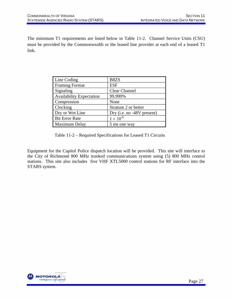
The minimum T1 requirements are listed below in Table 11-2. Channel Service Units (CSU) must be provided by the Commonwealth or the leased line provider at each end of a leased T1 link.
Line Coding B8ZS Framing Format ESF Signaling Clear Channel Availability Expectation 99.999% Compression None Clocking Stratum 2 or better Dry or Wet Line Dry (i.e. no -48V present) Bit Error Rate 1 × 10⁻⁶
Maximum Delay 5 ms one way
Table 11-2 – Required Specifications for Leased T1 Circuits Equipment for the Capitol Police dispatch location will be provided. This site will interface to the City of Richmond 800 MHz trunked communications system using (5) 800 MHz control stations. This site also includes five VHF XTL5000 control stations for RF interface into the STARS system.
Page 27
SECTION 11 COMMONWEALTH OF VIRGINIA INTEGRATED VOICE AND DATA NETWORK INTEGRATED VOICE AND DATA NETWORK
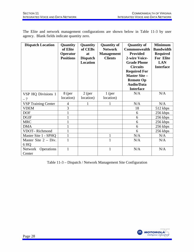
The Elite and network management configurations are shown below in Table 11-3 by user agency. Blank fields indicate quantity zero. Dispatch Location Quantity
of Elite Operator Positions
Quantity of CEBs
at Dispatch Location
Quantity of Network
Management Clients
Quantity of Commonwealth
Provided 2-wire Voice- Grade Phone
Circuits Required For Master Site – Remote Op Audio/Data
Interface
Minimum Bandwidth Required For Elite
LAN Interface
VSP HQ Divisions 1 – 7
8 (per location)
2 (per location)
1 (per location)
N/A N/A
VSP Training Center 4 1 1 N/A N/A VDEM 3 18 512 kbps DOF 1 6 256 kbps DGIF 1 6 256 kbps MRC 1 6 256 kbps DMA 1 6 256 kbps VDOT– Richmond 1 6 256 kbps Master Site 1 - SPHQ 1 1 N/A N/A Master Site 2 – Div. 6 HQ
1 1 N/A N/A
Network Operations Center
1 1 N/A N/A
Table 11-3 – Dispatch / Network Management Site Configuration
Page 28
COMMONWEALTH OF VIRGINIA SECTION 11 STATEWIDE AGENCIES RADIO SYSTEM (STARS) INTEGRATED VOICE AND DATA NETWORK
11.6.1. CENTRACOM Elite Console System CENTRACOM Elite (Appendix 5) is a software-based radio dispatch control center. The console utilizes a Graphical User Interface (GUI) screen that runs under Microsoft Windows on standard PCs, and uses an Ethernet Local Area Network (LAN). Each Elite operator position is equipped with the following:
• 17” LCD Flat Panel Touch Screen Monitor • Footswitch • Two Headset Jacks • Three Headsets • Desktop Remote Controller connected to a backup ASTRO Spectra Plus control station in
the equipment room • One 800 Watt UPS
The supervisory operator position has the highest priority of all Dispatch operators attached to the same Master Site and can override the transmissions of other operator positions. Each LMR Master Site can have one high-level “supervisory” dispatch operator position. This console will have the highest priority in the zone. Elite dispatch positions that interface to the same AEB (via CEB interface) will be subordinate to this high-level supervisory position. While there is only one Supervisory position per zone, multiple secondary supervisory positions can be assigned with slightly less supervisory capabilities. A secondary supervisory position can be utilized at each VSP Division Communications Center to meet the supervisory requirements of the Commonwealth. A secondary supervisory position can disable an entire subordinate console position. While disabled, this position cannot transmit or receive. Each console position will use a desktop Console Interface Electronics (CIE) to provide the audio interface to the dispatcher. A headset microphone connected to the CIE captures and transmits the dispatcher’s audio to the Central Electronics Bank (CEB). Radio traffic audio, received via the CEB, is heard by the dispatch operator through two loudspeakers mounted in the CIE. One of these speakers reproduces audio from ‘Selected’ resources and the other speaker reproduces audio from all ‘Unselected’ resources. Each has its own volume control. The CIE acts as an interface and format converter for data flowing between the Dispatch operator position and the CEB. When the operator headset is plugged in, the Select audio is routed to the headset and the Unselect audio continues to be heard through the Unselect speaker.
Page 29
SECTION 11 COMMONWEALTH OF VIRGINIA INTEGRATED VOICE AND DATA NETWORK INTEGRATED VOICE AND DATA NETWORK
Dispatch operator positions can see information about callers, call type and call status instantly. Resources and calling unit IDs can be identified by real names or numeric IDs. These real names are referred to as aliases and can be up to 14 characters in length. After a call is completed, the calling unit’s ID or alias will remain displayed until another call is received. Each individual resource has the capability of storing information on up to 10 calls in the resource’s stack. When the call type initiated by a user is an emergency call the dispatcher will see a flashing red border on the resource and will hear an audible tone. The dispatcher will be able to acknowledge the emergency and stop the tone and flashing border.
All call types of the console system will be displayed in an activity log. This activity log will display functions unique to the specific system radio protocols; namely, the resource alias, type of call and time of the last 1000 inbound calls. The calls will be displayed in a first in - first out basis. The activity log will have the capability of being placed anywhere on the screen. The activity log will be capable of being resized, fully hidden, or displayed completely to its full size. Each Elite console operator position can have up to 80 trunked resources assigned at a particular time. Each assigned non-trunked resource decreases this quantity by 2. Authorized personnel can edit/change the resources at any time. Over 1000 resources can be defined, with up to 80 (trunked only) assigned at one time. Any Elite operator position, interfaced to a particular Master Site (ASTRO 25 zone), can access the non-trunked resources of any CEB interfaced to the same Master Site. For example, VSP Division 1 can access any non-trunked resources (conventional BIMs) in VSP Division 2 since both are interfaced to the same Master Site. Trunked resources can be accessed anywhere within the system, by any Elite operator position in either zone, if the trunked talkgroup is configured as a ‘wide-area’ talkgroup. The SPHQ NOC will have access to all Elite operator positions in both zones.
11.6.1.1. Elite Local Area Network (LAN) Each Dispatch Control Room has its own local Elite / NM LAN. All dispatch site LANs are connected to their respective Master Site via an IP router and T1/FT1 interface.
11.6.2. Additional CENTRACOM Elite Operator Position Features The features available to the operator position include but are not limited to:
• alert tones • multi-select • patch • instant recall recording
Page 30
COMMONWEALTH OF VIRGINIA SECTION 11 STATEWIDE AGENCIES RADIO SYSTEM (STARS) INTEGRATED VOICE AND DATA NETWORK
While the actual configuration of the dispatch operator position will be programmed by an authorized user through the database applications, the dispatcher has the ability to adjust certain aspects of the resources on the screen. Namely, the dispatcher can change the location of the resources on the screen; expand and compress the resources; and adjust the volume of each resource independently. For example, the dispatcher can control the telephone receive audio while not affecting the volume of the radio receive audio coming through the speakers or headset jack.
11.6.2.1. Alert Tones The dispatcher has access to three different alert tones: single, warbling, and pulsed. Alert tones sound best when used on analog channels and will sound different when used on digital transmissions due to the vocoding process. Vocoding is the process of ‘voice coding’ audio to digital format. Motorola will implement priority marker alert tones in the digital mode (similar to the present VSP system).
11.6.2.2. Multi-Select Up to three Multi-Select function(s) are provided on each dispatch operator position that allows the dispatcher to simultaneously select two or more resources for transmission and reception, that is, multicast. These functions are represented by mini-folders with tabs indicating the name of each multi-select group. The resources within each multi-select group are held in memory for quick recall by the dispatcher and may be modified by the dispatcher at any time. Also, the names of each multi-select group can be changed by the dispatcher. The process to set up the multi-select is a follows. First, the multi-select mini-folder is selected. Then the desired resources are added to the mini-folder by a single-button press that selects the resource. At this time, a multi-select general transmit control is provided on the screen. This control provides the transmit function for all resources stored in the memory of the associated multi-select. Finally, the operator can now transmit and the audio will go out on all the resources stored. If, however, one of the resources in the multi-select is in use by a different dispatcher then this resource will be excluded from the transmission while the remaining resources are keyed.
11.6.2.3. Patch Up to 16 patch functions are provided on each dispatch operator position that permits patch control of two or more trunked talkgroups, conventional channel and/or phone resources. These functions are represented by mini-folders with tabs indicating the name of each patch group and include the name of the resources that are participating in the patch. A resource is added to or removed from a patch group with a single-button press that selects the resource. The dispatcher can monitor or transmit to any patch created at the operator position. Also, the dispatcher has priority and can break-in on a patch conversation at any time. There is no limit to the number of non-fixed users participating in a patch. When a patch has been inactive for more than 30 seconds, the tab of that mini-folder flashes to alert the operator of patch inactivity. A patch busy indication in the resource tile will be provided for a resource assigned to a patch group by another operator. Up to sixteen resources can be patched together if not already in a patch group at another dispatch position.
Page 31
SECTION 11 COMMONWEALTH OF VIRGINIA INTEGRATED VOICE AND DATA NETWORK INTEGRATED VOICE AND DATA NETWORK
Existing system base station equipment, that is interfaced via BIM, can be patched to ASTRO 25 system talkgroups providing a means of backward compatibility with legacy users. Patching between two or more conventional (non-trunked) digital stations, or between a non-trunked digital station and a digital talkgroup reduces audio quality and is not recommended due to the process of ‘double-vocoding’. Digital-to-analog and Analog-to-digital patches are not affected by double-vocoding. Digital-to-digital trunked talkgroup patching, within the ASTRO 25 system, is not affected by double-vocoding.
11.6.2.4. Instant Recall Recorder Each Elite dispatch console operator position is provided with a software-driven dual-channel Instant Recall Recorder (IRR) for all phones and radio audio handled by that dispatch position will be recorded on a first-in, first-out basis for at least one hour in length. The IRR is integrated on the Elite dispatch console computer screen and allows digital recording with search and playback of recordings. The IRR software allows control through a screen icon with IRR files stored on the Elite operator position computer. The IRR instant retrieval system includes the ability to attach text documents to recordings, a security feature, multiple playback, and real time audio monitor. Multiple playback allows the user to play back more than one recording at the same time, while real time audio monitor allows the user to listen to the last two minutes of a recording in progress without needing to stop recording in order to be able to listen. The IRR instant retrieval window allows the user to immediately access the radio and telephone recordings. The window initially opens on the newest recordings, but also allows access to any recordings on the system. The recording can also be saved to the WAV file that the user specifies. This is useful if a user wants to save a specific recording to a floppy disk or to a personal network directory.
11.6.2.5. Console Intercom The Elite intercom function operates on a selective basis between other Elite operators interfaced to the same Master Site equipment, and will be performed on a non-selective basis by Base Interface Module (BIM) interface between Elite operators connected to different Master Site equipment. The selective intercom function, when called upon, provides a list of those operators connected to the same zone, and that are available for selective intercom. To allow non-selective intercom communications between Elite operator positions across zones, a BIM will be installed in a CEB in one zone, and a like BIM will be installed in a CEB in the other zone. This will provide a non-selective intercom configuration, providing intercom communications across zones to other dispatch centers associated with the other Master Site equipment. One BIM is provided in both Zone 1 and Zone 2 for this non-selective intercom interface allowing one non-selective intercom call to be made across zones at a time
Page 32
COMMONWEALTH OF VIRGINIA SECTION 11 STATEWIDE AGENCIES RADIO SYSTEM (STARS) INTEGRATED VOICE AND DATA NETWORK
The non-selective intercom Elite screen user interface will be similar to a non-trunked base station console resource. The initiating dispatcher must choose the “intercom BIM” resource and address the desired operator (by voice). The receiving operator will hear the intercom call in the “unselect” speaker. Note that any other Elite position, with the particular “intercom BIM” as an assigned resource, will hear the intercom exchange. Motorola’s design ensures that all VSP Elite operators, within a particular VSP Division, are interfaced to the same Master Site equipment.
11.6.2.6. Additional Speaker Each VSP Elite operator position includes a third speaker that will be housed in an enclosure external to the CIE Select and Unselect speaker enclosure and will rest on the console furniture. The VSP must designate an audio resource for use with this speaker.
11.6.2.7. Console Phone Interface Dispatch operators can make and initiate telephone calls. This requires a phone line supplied by the Commonwealth that is interfaced at the SPHQ Master Site directly from the dispatch console without using a separate telephone. This is done using the on-screen user interface of the Elite operator position and the Elite console Smart Phone Interface (SPI). This feature provides a different functionality than trunked telephone interconnect, previously described. Incoming and outgoing telephone calls can be connected to talk-groups using the Elite console’s Patch feature. The SPI appears as a resource to the dispatcher, just as a radio resource, and can be patched accordingly up to the quantity of SPIs attached to a particular zone (Master Site). These calls will be full duplex (talk and hear at the same time) for the telephone user, and half-duplex for the radios (only one at a time can transmit). Each Elite-equipped dispatch location has one SPI designated for that location’s use, allowing one phone line to be interfaced at the respective CEB location. All non-VSP agency CEBs, and thus SPI’s phone line interfaces, are located at the SPHQ Master Site. Each Elite dispatch console, if so configured, can access any SPI that is interfaced to the same Master Site.
11.6.2.8. Console Furniture Motorola will provide the Commonwealth with modular, office-type furniture for console dispatch locations identified in this Contract. Motorola will work closely with the Commonwealth to ensure that console furniture is provided with the desired color schemes, and to ensure that sufficient furniture desktop space is provided. Console furniture designs will be based upon the dispatch drawings provided by the Commonwealth in Appendix 3, and additional detailed information provided by the VSP. Dispatch room drawings are attached in Appendix 3 based upon this information. Room dimensions require verification by the VSP, and VSP approval is required before
Page 33
SECTION 11 COMMONWEALTH OF VIRGINIA INTEGRATED VOICE AND DATA NETWORK INTEGRATED VOICE AND DATA NETWORK
the finalization of the dispatch furniture configurations. One dispatch furniture position will be provided for each VSP Elite dispatch operator position, for a total of 60 furniture positions. All other Commonwealth Agency (non-VSP) dispatch locations will utilize existing furniture. Each VSP Elite dispatch furniture position will be provided with a chair. The Dispatch room chairs have a membrane suspension with replaceable covers, adjustable lumbar support, knee tilt control adjustable armrests, and a six-leg base. The chairs have a 550lb warranty, and surpass the FAA requirements for ‘Intensive Use Seating”
11.6.2.9. VSP Backup RF Control Stations RF control stations, and associated antenna systems, will be provided at each VSP Elite dispatch console position provided at each of the seven Division Headquarters for use when the local ASTRO 25 repeater site reverts to Site Trunking, Failsoft, or the dispatch consoles become unavailable for any reason. Each Elite dispatch position will be provided with a remote desktop controller interfaced to its respective dedicated ASTRO Spectra Plus, 50-Watt control station located in the equipment room. The RF control stations operate independently from the Elite dispatch console subsystem. Each RF control station will include a separate antenna system with up to 200 feet of non plenum-rated transmission line. If non-plenum is used, then conduit is required in plenum rated installation areas. Motorola is responsible for placement of antennas.
11.6.2.10. MDC 1200 / GSTAR / DTMF / Legacy Equipment Interface Motorola’s Elite dispatch system provides compatibility with existing MDC 1200 non-trunked, non-fixed users, for Push-to-Talk (PTT) ID, on two VSP channels at each VSP Division dispatch location using hardware internal to the console. MDC 1200 PTT IDs will be displayed on the Elite console screen. Additionally, Motorola will provide two external GSTAR/DTMF decoder units with each VSP Elite dispatch position, and one external GSTAR/DTMF decoder unit for MRC Elite dispatch position, to provide PTT ID from existing non-trunked, non-fixed units using GSTAR and DTMF signaling. The external GSTAR/DTMF display unit will rest on the provided console furniture at VSP locations, and on existing furniture at non-VSP Agency locations, and the GSTAR/DTMF PTT ID will be provided on the display unit. Each external GSTAR/DTMF display unit will provide an audio interface for one RF channel. The interface point, for each VSP external GSTAR/DTMF display unit, will be the voted audio interface point at the local respective CEB. The interface point for each non-VSP external GSTAR/DTMF display unit will be the analog legacy station’s audio interface point at the respective RF site. One Commonwealth-provided two-wire phone quality circuit will be required from the SPHQ Master Site to the respective RF station, at the respective RF site, to provide the GSTAR/DTMF data to the desktop decoder located at the dispatch location. Each GSTAR/DTMF display unit, operating on the same channel, will be wired in parallel with other units operating on that same channel. The channels used in conjunction with MDC 1200, GSTARS, and DTMF signaling are understood to be analog (non-digital) channels.
Page 34
COMMONWEALTH OF VIRGINIA SECTION 11 STATEWIDE AGENCIES RADIO SYSTEM (STARS) INTEGRATED VOICE AND DATA NETWORK
Motorola will provide up to seventy 1950 Hz ‘pilot’ tone generators, one for each existing VSP LMR station, based upon the voter configuration information in Appendix 3. The pilot tone generator will be used to indicate to the existing LMR stations that the station-to-voter link is active, and will be used to ‘force’ the existing stations to operate as a base station. It is understood that each existing LMR station reverts to in-cabinet repeat upon loss of the 1950 Hz pilot tone. Each pilot tone generator will be bridged (parallel circuit) onto the console-to-station transmit circuit. A console Form C relay will deactivate the pilot tone generator upon console Push-to-Talk (PTT). Each existing VSP LMR station will be interfaced to a dedicated Base Interface Module (BIM) for audio, and keyed using a closure transmitted via M-Lead (dispatch site-to-LMR site) signaling over the microwave system. Some VSP LMR sites utilize existing standby stations in the event of a primary station failure. It is understood that a single 4-wire circuit is required between the voter and the primary/standby station location, and that on-site switching, between these stations, is manually performed by VSP Service personnel using existing equipment and/or procedures. MOSCAD (LMR site-to-dispatch site) signaling will be used to transmit a closure, from the standby station to the console, to indicate that the standby station is active. This closure must be provided by the existing standby station. All existing equipment interfaces must be provided at a mutually agreed to point of demarcation within 15 cable feet of the equipment at each site. The proper operation of all existing equipment is the responsibility of the Commonwealth. All existing equipment interfaces to the ASTRO 25/Elite system are based upon information in Appendix 2, and it is understood that the above existing system interfaces and equipment will be used with analog (non-digital) stations/radios. The legacy system configuration information must be confirmed by the VSP/Commonwealth before the ASTRO 25/Elite system-to-existing system interfaces/configuration can be finalized.
11.6.2.11. Netclock GPS Time Synchronization Each VSP Divisional Headquarters dispatch center, each non-VSP dispatch center, and the VSP Training Center are provided with a GPS Netclock to provide a “time stamp” for use with existing collocated VSP equipment that is capable of utilizing the synchronization signal. The GPS Netclock includes an antenna, transmission line surge protector, and up to 100’ of non plenum-rated transmission line for outside antenna mounting. If non-plenum is used, then conduit is required in plenum rated installation areas. The Commonwealth is responsible for the interface to any existing dispatch center equipment and any additional equipment required for these interfaces. Elite consoles and network management clients do not
Page 35
SECTION 11 COMMONWEALTH OF VIRGINIA INTEGRATED VOICE AND DATA NETWORK INTEGRATED VOICE AND DATA NETWORK
require an interface to the Netclock equipment for time synchronization, because they receive their time synchronization from the Master Site through the ASTRO 25 network. The Commonwealth will identify a suitable mounting location, on each respective dispatch location rooftop, for the Netclock GPS antenna, and the shortest, most direct route available to the roof for the associated transmission line.
11.6.2.12. Logging Recorder Motorola will provide a 48-channel logging recorder for each of the dispatch locations as indicated in Table 11-3. The 48-channel recorder will allow the Commonwealth to record conventional telephony and radio communications. The recorder is computer-based and has a hard drive, Pentium Processor, and operates using the Windows operating system. It supports up to 128 channels in a single chassis and records radio or telephony to DVD or VXA-1 Tape. Motorola will provide a 48-channel equipped recorder using DVD as the long-term storage recording media. The 48-channel recorder provides simultaneous record and playback with archiving to local or remote media. User interface control and configuration is via a web browser, and allows for local or remote maintenance over a LAN or WAN. Recordings are stored locally to a hard drive prior to being archived to removable media. Calls can be replayed from recordings that are available on the local hard drive or from the offline media. Only authorized PCs on the same network as the recorder, and with a web browser, will have the ability to manage the recording system. No dedicated equipment or software is required, although an enhanced tools software package is included and will be installed on up to ten compatible existing PC workstations per recorder location. Each logging recorder will be equipped with a Mainframe chassis, a 74 GB hard drive capable of storing up to 12,400 channel hours, dual DVD RAM drives, a PC administrative workstation, and a UPS for up to 35 minutes of operation in the event of a power failure.
11.6.2.13. Logging Recorder Motorola will provide each dispatch locations with a TASCAM CD-RW402 CD Recorder/Duplicator to allow distribution of logging recorder audio onto standard CDs. The TASCAM CD-RW402 will be a stand-alone device.
11.6.3. Central Electronics Bank (CEB) In order to get the audio to and from the Elite operator positions, a Central Electronics Bank (CEB) is provided. The CEB is the "brain" of the CENTRACOM Gold Elite dispatch system and serves to connect operator positions to the radio system infrastructure. Individual dispatch positions are connected to the CEB and the CEB is connected to the radio communications system via the AEB.
Page 36
COMMONWEALTH OF VIRGINIA SECTION 11 STATEWIDE AGENCIES RADIO SYSTEM (STARS) INTEGRATED VOICE AND DATA NETWORK
The CEB takes analog audio from the Elite Console Interface Electronics (CIE), converts it to Pulse Code Modulation (PCM) audio, and multiplexes it together with signaling information from the CIE into a Time Division Multiplex (TDM) T1 format to interface to the AEB. In the other direction, the CEB de-multiplexes the incoming PCM audio from the AEB, converts it to analog audio for distribution to the CIE together with the signaling information. CEBs will be located at the Zone Master Sites (collocated) and at VSP remote dispatch sites. They will be mounted in standard 19” equipment racks. The following sections outline the Elite operator position CEB configurations that are provided to the Commonwealth by agency. These configurations are preliminary, pending a technical design review with Commonwealth personnel, and require mutual Motorola and Commonwealth approval before finalization. Changes to the CEB hardware, to ensure that the proper interfaces are provided for existing subsystems, can be identified and quoted during the Contract Design Review period. The provided Elite dispatch locations are detailed below by user Agency.
11.6.3.1. VSP Divisional Headquarters Each of the seven VSP Divisional Headquarters (HQ) dispatch locations will have two CEBs that are sized together to accommodate eight Elite operator positions, one sixteen-channel de-trunked logging recorder interface, one phone interface, and non-trunked channel control hardware as follows:
• Each VSP Divisional dispatch location will support MDC 1200 signaling, on the two VSP voted analog channels, using a total of twelve specifically equipped T1R1 BIMs. This equipment will be used in conjunction with the VSP legacy system equipment.
• Each Division HQ dispatch location is provided with four ‘Comparator Interface
Modules’. Each of the two VSP voted channels will use two Comparator Interface Modules to provide voter indications for up to six remote RF sites, by contact-closure interface to the existing voter. The existing voter must be capable of a discrete contact-closure interface. The voter and CEB must be located in adjacent racks as a maximum of 200 cable feet will be allowed between the CEB and the respective I/O in the voter. This equipment will be used in conjunction with the VSP legacy system equipment. The Commonwealth is responsible for the proper operation of the existing legacy equipment.
• Three T1R1 BIMs are provided for interfacing up to three collocated,
Commonwealth-furnished, RF control stations used for local inter-agency interoperability. These RF control stations must be located inside the CEB equipment room, or a point of demarcation must be provided by the Commonwealth in the CEB equipment room, for interface to the CEB.
Page 37
SECTION 11 COMMONWEALTH OF VIRGINIA INTEGRATED VOICE AND DATA NETWORK INTEGRATED VOICE AND DATA NETWORK
• Three T1R1 BIMs are provided to provide a ‘non-selective’ intercom audio interface to up to three existing collocated door intercoms. The BIM interface to the existing door intercoms will provide a 2/4-wire audio path, from the respective Division’s Elite consoles, to the respective door intercoms. Motorola will provide the BIM audio interface to a point of demarcation in the CEB equipment room, and the Commonwealth will interface the intercom audio to that point. From this demarcation location, the interface and proper operation of the existing intercom system is the responsibility of the Commonwealth.
Additional interfaces, if required, can be quoted if needed. Additional interfaces may require additional links and/or CEBs to implement.
11.6.3.1.1. Door Intercom The non-selective door intercom Elite screen user interfaces will be similar to a non-trunked base station console resource. The initiating dispatcher must choose the door intercom BIM resource and address the desired door intercom (by voice). Note that any other Elite position, with the particular “intercom BIM” as an assigned resource, will hear the intercom voice exchange. This user screen interface will be used in conjunction with existing capable Commonwealth-provided intercom equipment.
11.6.3.1.2. I/O Expansion Motorola is providing one expansion card with a total of 16 Input/Output (I/O) points at each VSP Divisional dispatch location to allow the VSP to monitor, or control, various local functions from the local Elite consoles. A maximum of 1000 cable feet (due to technical limitations) will be allowed between the CEB and the respective I/O. Motorola will provide the I/O interface to a point of demarcation in the CEB equipment room, and the Commonwealth will interface the respective I/O to that point. Compatible sensors and/or control circuitry must be provided by the Commonwealth that provides or accepts a dry contact closure from the CEB.
11.6.3.1.3. Logging Recorder Interface A sixteen-track de-trunked logging recorder interface, at each VSP Divisional dispatch location, is provided that allows trunked talkgroup audio to be recorded in a coherent manner on a co-located logging recorder track.
11.6.3.1.4. Operator Interface / CEB – AEB Interface The interface between the CEB and each Elite operator position consists of a 7-pair cable, currently provided with a length of 200 feet. The system is limited to a maximum distance of 2000 cable feet between the Elite operator positions and the respective CEB, and with both being within the same building. If console operator positions must be located in a separate building or
Page 38
COMMONWEALTH OF VIRGINIA SECTION 11 STATEWIDE AGENCIES RADIO SYSTEM (STARS) INTEGRATED VOICE AND DATA NETWORK
greater than 2000 feet from the CEB, a Remote Operator Interface is required. Distances greater than 200 cable feet are required and a Remote Operator Interface is required in Division 1. The CEB will be located in the same building as the other VSP dispatch centers. Each VSP Divisional HQ CEB interfaces to two Ambassador (AMB) cards, in the AEB, via redundant microwave T1 links. Each Divisional HQ dispatch location requires seven T1s, between the Elite / network management LAN and the two CEBs and the AEB located at the respective Master Site. Refer to the Virginia State Police Typical Dispatch Site Block Diagram in Appendix 3.
11.6.3.2. VSP Training Center The VSP Training Center dispatch location will have one CEB that is sized to accommodate four Elite operator positions, one sixteen-channel de-trunked logging recorder interface, one phone interface, and non-trunked channel control hardware as follows:
• Four T1R1 BIMs are provided for interfacing up to four collocated Commonwealth-provided RF control stations.
• Three T1R1 BIMs are provided to provide a ‘non-selective’ intercom audio interface
to up to three existing collocated door intercoms. The BIM interface to the existing door intercoms will provide a 4-wire audio path, from the VSP Training Center Elite consoles, to the respective door intercoms. Motorola will provide the BIM interface to a point of demarcation in the CEB equipment room, and the Commonwealth will interface the intercom audio to that point. From this demarcation location, the interface and proper operation of the existing intercom system is the responsibility of the Commonwealth.
11.6.3.2.1. Door Intercom The non-selective door intercom Elite screen user interfaces will be similar to a non-trunked base station console resource. The initiating dispatcher must choose the door intercom BIM resource and address the desired door intercom (by voice). Note that any other Elite position, with the particular “intercom BIM” as an assigned resource, will hear the intercom voice exchange. This user screen interface will be used in conjunction with existing capable Commonwealth-provided intercom equipment.
1.6.3.2.2. I/O Expansion Motorola is providing one expansion card providing a total of 16 Input/Output (I/O) points at the VSP Training Center dispatch location to allow the VSP to monitor, or control, various local functions from the local Elite consoles. A maximum of 1000 cable feet (due to technical limitations) will be allowed between the CEB and the respective I/O. Motorola will provide the I/O interface to a point of demarcation in the CEB equipment room, and the Commonwealth will interface the respective I/O to that point. Compatible sensors and/or control circuitry must be provided by the Commonwealth that provides or accepts a dry contact closure from the CEB.
Page 39
SECTION 11 COMMONWEALTH OF VIRGINIA INTEGRATED VOICE AND DATA NETWORK INTEGRATED VOICE AND DATA NETWORK
11.6.3.2.3. Logging Recorder Interface A sixteen-track de-trunked logging recorder interface is provided that allows trunked talkgroup audio to be recorded in a coherent manner on a collocated logging recorder track. The interface between the CEB and each Elite operator position consists of a 7-pair cable, currently provided with a length of 200 feet. The system is limited to a maximum distance of 2000 cable feet between the Elite operator positions and the respective CEB, and with both within the same building.
11.6.3.2.4. Operator Interface / CEB – AEB Interface The interface between the CEB and each Elite operator position consists of a 7-pair cable, currently provided with a length of 200 feet. The system is limited to a maximum distance of 2000 cable feet between the Elite operator positions and the respective CEB, and with both being within the same building. If console operator positions must be located in a separate building or greater than 2000 feet from the CEB, a Remote Operator Interface is required. If distances greater than 200 cable feet are required or a Remote Operator Interface is required, the additional equipment will be quoted separately. The VSP Training Center CEB interfaces to two Ambassador (AMB) cards, in the AEB, via redundant Commonwealth-provided Microwave T1 links. The Training Center dispatch location requires five T1 links via the Microwave Network using an existing VSP fiber optic cable, between the VSP Training Center dispatch equipment room and the SPHQ Master Site.
11.6.3.3. Non-VSP Agencies Each of the non-VSP Agency dispatch locations identified in Table 11-3 will use a respective quantity of Elite dispatch console positions (located at the respective dispatch site) interfaced to remote CEBs that are located at the SPHQ Master Site. The CEBs are sized to accommodate the provided non-VSP Elite operator positions, one eight-channel de-trunked logging recorder interface (per dispatch site), one phone interface (per dispatch site), I/O expansion, and the non-trunked channel control hardware as follows.
Page 40
COMMONWEALTH OF VIRGINIA SECTION 11 STATEWIDE AGENCIES RADIO SYSTEM (STARS) INTEGRATED VOICE AND DATA NETWORK
• The MRC dispatch location will support MDC 1200 signaling using a total of five specifically equipped T1R1 BIMs -- one per (up to four) receive sites for a single analog channel, plus one for the (voter) voted audio output. The MRC voted channel will be provided with one Comparator Interface Module to provide voter indications for up to four remote RF sites on a single channel, by contact-closure interface to the existing voter. The existing voter must be capable of a discrete contact-closure interface to the CEB. The voter and CEB must be located in adjacent racks as a maximum of 200 cable feet will be allowed between the CEB and the respective I/O in the voter. Note that the CEB provided for the MRC dispatch console is located at the SPHQ Master Site. The Commonwealth is responsible for providing the CEB-to-RF site links for all non-VSP agencies between the SPHQ Master Site and the respective RF equipment site. This equipment will be used in conjunction with the non-VSP legacy system equipment.
• T1R1 BIMs are provided for interfacing Commonwealth-provided collocated RF
control stations, wireline interfaced tone control base stations (legacy system equipment), or ‘non-selective’ intercom audio. The total respective quantities of provided BIMs, per non-VSP agency, are listed in Table 11-4.
11.6.3.3.1. Door Intercom The BIM interface-to-existing door intercoms will provide a 2/4-wire audio path, from the respective Elite console CEB, to the respective collocated door intercoms. Motorola will provide the BIM audio interface to a point of demarcation in the CEB equipment room, and the Commonwealth will be required to interface the intercom audio to that point. Note that the CEBs provided for the non-VSP Agency dispatch consoles are located at the SPHQ Master Site and Commonwealth-provided links will need to be in place for this interface to operate properly. The interface and proper operation of the existing intercom system is the responsibility of the Commonwealth. The non-selective door intercom Elite screen user interfaces will be similar to a non-trunked base station console resource. The initiating dispatcher must choose the door intercom BIM resource and address the desired door intercom (by voice). Note that any other Elite position, with the particular “intercom BIM” as an assigned resource, will hear the intercom voice exchange.
Page 41
SECTION 11 COMMONWEALTH OF VIRGINIA INTEGRATED VOICE AND DATA NETWORK INTEGRATED VOICE AND DATA NETWORK
11.6.3.3.2. I/O Expansion Motorola provides one expansion card providing a total of 16 Input/Output (I/O) points at each non-VSP dispatch location to allow the respective agencies to monitor, or control, various local functions from the Elite consoles. Because the CEB equipment is located at the SPHQ Master Site location, MOSCAD equipment will be used to transmit I/O information between the CEB and the respective dispatch location. The MOSCAD is configured to provide eight inputs and eight outputs between each respective non-VSP dispatch location and the SPHQ Master Site. A maximum of 1000 cable feet (due to technical limitations) will be allowed between the CEB and MOSCAD equipment. Motorola will provide the MOSCAD I/O interface to a point of demarcation in each dispatch equipment room, and the Commonwealth will be required to interface the respective I/O to that point. Compatible sensors and/or control circuitry must be provided by the Commonwealth that provides or accepts a dry contact closure from the CEB.
11.6.3.3.3. Logging Recorder Interface An eight-track de-trunked logging recorder interface, at each non-VSP dispatch location, is provided that allows trunked talkgroup audio to be recorded in a coherent manner on a logging recorder track. It should be noted that the de-trunked logging recorder interface is located in the respective CEB and all logged audio must be transported to the respective dispatch location (logging recorder location) via Commonwealth-provided leased phone circuits.
11.6.3.3.4. Operator Interface / CEB – AEB Interface The interface between the CEB, located at the SPHQ Master Site, and each remote Elite operator position consists of six voice quality circuits as outlined in Table 11-3 using a console Remote Operator Interface. Additionally, each non-VSP dispatch location requires a Fractional T1 (FT1) circuit to transport Elite LAN data between the SPHQ Master Site and the respective dispatch location. Each of these circuits must be provided by the Commonwealth. The SPHQ Master Site CEBs, that are interfaced to the non-VSP agency Elite operator positions and that house the respective Agency BIMs, also house the ‘Locality Interface’ and Agency Interface BIMs and the BIMs associated with the future VHF analog Mutual Aid stations located at each LMR RF site. Motorola is providing a total of 306 BIMs to be used in conjunction with the ‘Locality Interfaces’ and Agency Interfaces. These BIMs will be distributed between multiple CEBs located at the two Master Sites. These BIMs are allocated for use with any of the RF site-located, Motorola -provided, RF control stations and base stations used for Locality and Agency Interfaces. Table 11-4 outlines the respective non-VSP dispatch BIM configuration. The BIM quantities and configurations outlined below for non-VSP agencies are assumed pending additional information being provided by the Commonwealth. Note that until Motorola is provided with the site locations for each of the non-VSP agency RF sites, that will utilize the provided non-VSP Agency BIMs, it is assumed that the respective agencies will use Commonwealth-provided 4-wire leased phone line circuits to the T1R1 (non-trunked) BIMs.
Page 42
COMMONWEALTH OF VIRGINIA SECTION 11 STATEWIDE AGENCIES RADIO SYSTEM (STARS) INTEGRATED VOICE AND DATA NETWORK
Dispatch Center MDC 1200 T1R1 BIM T1R1 BIM VDEM 0 10 DOF 0 10 DGIF 0 10 MRC 5 5 DMA 0 5 VDOT - Richmond 0 10
Table 11-4 – Non-VSP Agency BIM Configuration Additional information must be provided to Motorola regarding the legacy system configuration/requirements for all non-VSP agencies, including the MRC voting system, and non-VSP RF site locations, in order to finalize the non-VSP Agency dispatch configuration. Refer to the Typical Non-VSP Dispatch Site Block Diagram in Appendix 3.
11.6.3.4. Capitol Police The Capitol Police dispatch location will be provided with five 800 MHz control stations to interface into the City of Richmond, Virginia Motorola 800 MHz trunked radio system. A translator computer and RF control channel monitor will be utilized to provide trunked Push-to-Talk (PTT) IDs and emergency alarms from the Richmond trunked system to the Elite display. It is assumed that the Capitol Police dispatch location is within the RF coverage area of the Richmond 800 MHz trunked radio system. Motorola will provide Capitol Police five desktop remote controllers connected to a 50 Watt VHF ASTRO Spectra Plus RF control station located in the equipment room. These control stations are for operation on the STARS VHF system. The RF control stations operate independent. Each RF control station will include a separate antenna system with up to 200 feet of non plenum-rated transmission line. The Commonwealth is responsible for providing a suitable mounting structure, on each respective dispatch location rooftop, for these antennas; and the shortest, most direct route to the roof for the associated transmission lines.
Page 43
SECTION 11 COMMONWEALTH OF VIRGINIA INTEGRATED VOICE AND DATA NETWORK INTEGRATED VOICE AND DATA NETWORK
11.7 STARS ASTRO 25 SYSTEM ENCRYPTION
[CONFIDENTIAL/PROPRIETARY Information – EXEMPT from public disclosure]
11.7.1. Over-the-Air Rekeying [CONFIDENTIAL/PROPRIETARY Information – EXEMPT from public disclosure]
11.8 EQUIPMENT SPARES Spares are being provided for much of the ASTRO 25 IV&D system equipment to allow replacement in the event of an equipment failure. Motorola is providing spares as shown in Appendix 8. These spares will be stored in VSP facilities. In conjunction with the Warranty and Support Plan, in Section 15, a distribution plan for equipment spares will be developed to promote optimal response times .
Page 44
COMMONWEALTH OF VIRGINIA SECTION 11 STATEWIDE AGENCIES RADIO SYSTEM (STARS) INTEGRATED VOICE AND DATA NETWORK
11.9 ASTRO 25 INTEGRATED VOICE AND DATA SYSTEM NETWORK SECURITY
11.9.1. Network Security Overview [CONFIDENTIAL/PROPRIETARY Information – EXEMPT from public disclosure]
11.9.1.1. Network Interface Barrier [CONFIDENTIAL/PROPRIETARY Information – EXEMPT from public disclosure]
11.9.1.2. Service Interface Barrier [CONFIDENTIAL/PROPRIETARY Information – EXEMPT from public disclosure]
11.9.1.3. Network Anti-Virus [CONFIDENTIAL/PROPRIETARY Information – EXEMPT from public disclosure]
Page 45

SECTION 11 COMMONWEALTH OF VIRGINIA INTEGRATED VOICE AND DATA NETWORK INTEGRATED VOICE AND DATA NETWORK
11.9.1.4. Network Security Services Motorola will provide a suite of network security products and services in order to fulfill the Commonwealth’s need to prevent, detect, and respond to security incidents. A pre-tested anti-virus subscription is included as part of the Warranty and Support Plan. Refer to the Warranty and Support Plan in Section 15 for the details regarding Network Security Services.
11.10 ASTRO 25 INTEGRATED VOICE AND DATA SYSTEM RELIABILITY The STARS system is designed for reliability to provide some level of communications when equipment failures occur that affect various parts of the system. The ASTRO 25 IV&D system is designed to survive multiple failures and continue to provide some level of communications within the system, depending upon the severity of the failure and its location(s).
11.10.1. Control Channel Failure Each remote ASTRO 25 Repeater Site is provided with multiple VHF 125 Watt QUANTAR repeater stations. One channel continuously transmits 9600 bps control channel data that directs mobiles and portables to the proper assigned voice channel and provides control channel signaling features. In the event of a control channel failure, another channel at the same site will take over the control channel function and the failed channel will be taken out of service.
11.10.2. Voice Channel Failure In the event of a voice channel failure, the failed channel will be taken out of service and that channel will no longer be assigned by the system. Effectively, the available talkpaths at the failed channel’s site will be reduced by only one.
11.10.3. Multiple Mode Failures of Control System Components The ASTRO 25 IV&D system is designed to ensure that multiple failures of control system components will not cause the ASTRO 25 Repeater Site to be beyond being usable as a “conventional” radio system. Motorola describes this “conventional” type operation as “Failsoft” operation. When operating in Failsoft voice users are alerted by an intermittent tone, and a visual display in display capable radios. ASTRO 25 Repeater Site processing power resides at each ASTRO 25 Repeater Site to allow the respective site to continue to trunk voice calls without any communications to the Master Site, and is capable of operating solely on local processing.
11.10.3.1. Loss of Functionality at any entire site If an entire ASTRO 25 repeater site loses total functionality, that particular site, and the associated wide-area RF coverage it provides, will not be available. In this situation, the VHF 125 Watt DRTCS can be deployed and operated in the “Site Trunking” configuration to provide local trunked communications. Otherwise, the user’s mobile and portable radio units will search for an adjacent ASTRO 25 repeater site within RF coverage range, if available.
Page 46
COMMONWEALTH OF VIRGINIA SECTION 11 STATEWIDE AGENCIES RADIO SYSTEM (STARS) INTEGRATED VOICE AND DATA NETWORK
11.10.3.2. Failure of all Console Positions at any Communications Center If a Master Site failure occurs, to the extent that all associated ASTRO 25 Repeater Sites operate in site trunking, the Elite dispatch consoles will not be used to dispatch trunked calls. In this situation, the RF control stations provided with each Elite dispatch operator position will be utilized independently from the Elite dispatch console, allowing voice dispatch communications to continue with the dispatch location. The consoles will continue to provide dispatch to any non-trunked channels if the BIM to station links are available and the local dispatch console system is operational. Where only a single dispatch operator position is available in a particular Dispatch location, a computer failure would render the position inoperable. For this situation, the Dispatch position’s RF control station and associated antenna system would be used for voice communications to a local ASTRO 25 Repeater Site.
11.10.3.3. Failure of Site Control Equipment Each LMR ASTRO 25 repeater site utilizes QUANTAR stations interfaced to a PSC 9600 site controller. The PSC 9600 is provided in a redundant configuration ensuring that the loss of a single Site Controller does not cause an ASTRO 25 site to lose trunking capability. In the event that both PSC 9600s fail, the site will revert to Failsoft, allowing voice communications to continue with other users operating on the respective ASTRO 25 repeaters as conventional channels.
11.10.3.4. Simultaneous Loss of the Radio Channels The ASTRO 25 LMR IV&D system is designed to ensure that some level of trunked communications is maintained even in the event of losing multiple channels at a particular ASTRO 25 Repeater Site. The ASTRO 25 system will continue to provide trunked operation as long as three or more of a site’s channels remain operational.
11.10.3.5. Causes Loss of Multi-Site Controls or Networking The Master Sites contain the overall control equipment for the ASTRO 25 IV&D system. The provided system utilizes two Master Sites, each controlling respective system resources (ASTRO 25 Repeater Sites, Dispatch Sites, etc.). In the event of a complete Master Site failure, the trunked resources (repeaters) located at the respective ASTRO 25 repeater site, will continue to operate in the Site Trunking configuration. When operating in Site Trunking, each ASTRO 25 Repeater Site provides trunked voice communications within the coverage area provided by the particular RF site, and voice users can communicate with other voice users operating on the same site.
11.10.3.6. Causes Loss of Trunking Capabilities for any Reason The ASTRO 25 LMR IV&D system is designed to ensure that multiple failures of control system components will not cause an ASTRO 25 Repeater Site to be beyond being usable as a “conventional” radio system. Motorola describes this “conventional” operation as “Failsoft” operation. When operating in Failsoft, users are alerted by an intermittent tone, and a visual display in display capable radios. When operating in Failsoft, voice users can communicate
Page 47
SECTION 11 COMMONWEALTH OF VIRGINIA INTEGRATED VOICE AND DATA NETWORK INTEGRATED VOICE AND DATA NETWORK
with other voice users, on the same Failsoft channel, within the RF coverage area of the same site. Back-up RF control stations, at each Elite dispatch position, will be used during Failsoft operation to communicate with every transmitter site within that VSP Division.
11.10.3.7. Degrades Non-Critical Subsystem Features The ASTRO 25 system utilizes different means for fault distribution to ensure that some level of communications continues even when multiple faults occur. Critical communications do not rely on non-critical subsystem functionality. For example, if the telephone interconnect subsystem fails, it does not affect the system’s ability to provide trunked voice communications. If the network management system fails, the LMR system continues to provide communications although the network management features may be lost. Also, due to the two-zone architecture, equipment failures in one zone, do not necessarily affect the operation of the equipment in the other zone.
11.11 VSP DISPATCH ADMINISTRATIVE PHONE SYSTEM Motorola will provide an administrative telephone system at each of the seven VSP Division HQ and the VSP Training Center. The phone system will interface to the Elite console system at the headset level, using carbon-biased headsets, providing dispatchers with the capability to use the Elite headset to receive and transmit full duplex phone call audio (one line at a time), based upon the phone line selected at the dispatch position. While the telephone circuit is off-hook, when the dispatcher push-to-talks (PTT) on the selected radio channel, the dispatcher’s audio will be routed to the radio channel while muting audio to the phone system. When off-hook, telephone audio will be routed to the dispatcher’s headset, and the selected radio channel’s audio will revert to the select speaker. Outbound calls (VSP-to-phone line) will be made manually by dispatchers using the computer keyboard’s numeric keypad or by using the on-screen speed dial-buttons, or automatically by program commands routed and interfaced from the PRC CAD. Each phone system location will be capable of providing answering position number and Caller ID to the CAD system. Each VSP Divisional HQ dispatch location will be provided with a PBX equipped with cards for up to 64 2-wire POTS (regular, analog service) administrative lines (64 lines max) for interface to the public telephone system and eight 24-button telephone desk sets (one per Elite operator position). The VSP training center will be equipped similarly, except with a quantity of four 24-button telephone desk sets (one per Elite operator position). Although the 24-button desk sets do not have to be used on a regular basis, they are being provided in the event of a monitor failure to allow phone system usage to continue. A portion of the provided 64 2-wire POTS line interfaces will be used in conjunction with the microwave system for the microwave telephone system. Refer to the Microwave section for details on the microwave telephone system.
Page 48
COMMONWEALTH OF VIRGINIA SECTION 11 STATEWIDE AGENCIES RADIO SYSTEM (STARS) INTEGRATED VOICE AND DATA NETWORK
• The phone system will be an integrated part of the radio system console. The headset audio to/from the dispatcher will allow phone and radio audio to be routed to/from each.
• The telephone system control functions will be integrated into the same flat
touchscreen / mouse driven monitor of the radio console. All lines with caller ID will be displayed on this monitor. Other functions incorporated will include but not be limited to hold, Caller ID, speed dial capabilities, manual or automatic line select, conference, mute, drop.
Caller ID information and console position identifier will be routed and interfaced into the PRC CAD for incident tracking. Call trace and caller ID pass-through will be available through these phones and have caller ID on all new phones installed.
Page 49